EP0699839A1 - Panel releasably lockable to a frame - Google Patents
Panel releasably lockable to a frame Download PDFInfo
- Publication number
- EP0699839A1 EP0699839A1 EP95114739A EP95114739A EP0699839A1 EP 0699839 A1 EP0699839 A1 EP 0699839A1 EP 95114739 A EP95114739 A EP 95114739A EP 95114739 A EP95114739 A EP 95114739A EP 0699839 A1 EP0699839 A1 EP 0699839A1
- Authority
- EP
- European Patent Office
- Prior art keywords
- panels
- sides
- panel
- screen
- frame
- Prior art date
- Legal status (The legal status is an assumption and is not a legal conclusion. Google has not performed a legal analysis and makes no representation as to the accuracy of the status listed.)
- Granted
Links
- 238000012216 screening Methods 0.000 claims abstract description 27
- 210000002105 tongue Anatomy 0.000 claims 1
- 230000003014 reinforcing effect Effects 0.000 abstract description 2
- 230000000979 retarding effect Effects 0.000 abstract 1
- 229920002635 polyurethane Polymers 0.000 description 10
- 239000004814 polyurethane Substances 0.000 description 10
- 238000004873 anchoring Methods 0.000 description 4
- 229920003023 plastic Polymers 0.000 description 4
- 239000004033 plastic Substances 0.000 description 4
- 229910000746 Structural steel Inorganic materials 0.000 description 3
- 230000001419 dependent effect Effects 0.000 description 2
- 238000007688 edging Methods 0.000 description 2
- 238000003780 insertion Methods 0.000 description 2
- 230000037431 insertion Effects 0.000 description 2
- 238000009434 installation Methods 0.000 description 2
- 230000004048 modification Effects 0.000 description 2
- 238000012986 modification Methods 0.000 description 2
- 239000002991 molded plastic Substances 0.000 description 2
- 210000003739 neck Anatomy 0.000 description 2
- 239000007787 solid Substances 0.000 description 2
- YPFNIPKMNMDDDB-UHFFFAOYSA-K 2-[2-[bis(carboxylatomethyl)amino]ethyl-(2-hydroxyethyl)amino]acetate;iron(3+) Chemical compound [Fe+3].OCCN(CC([O-])=O)CCN(CC([O-])=O)CC([O-])=O YPFNIPKMNMDDDB-UHFFFAOYSA-K 0.000 description 1
- 230000001154 acute effect Effects 0.000 description 1
- 230000000694 effects Effects 0.000 description 1
- 239000013536 elastomeric material Substances 0.000 description 1
- 238000004519 manufacturing process Methods 0.000 description 1
- 239000000463 material Substances 0.000 description 1
- 230000013011 mating Effects 0.000 description 1
- 239000002184 metal Substances 0.000 description 1
- 229910052751 metal Inorganic materials 0.000 description 1
- 238000000465 moulding Methods 0.000 description 1
- WTGQALLALWYDJH-WYHSTMEOSA-N scopolamine hydrobromide Chemical compound Br.C1([C@@H](CO)C(=O)OC2C[C@@H]3N([C@H](C2)[C@@H]2[C@H]3O2)C)=CC=CC=C1 WTGQALLALWYDJH-WYHSTMEOSA-N 0.000 description 1
- 238000003466 welding Methods 0.000 description 1
Images



Classifications
-
- B—PERFORMING OPERATIONS; TRANSPORTING
- B07—SEPARATING SOLIDS FROM SOLIDS; SORTING
- B07B—SEPARATING SOLIDS FROM SOLIDS BY SIEVING, SCREENING, SIFTING OR BY USING GAS CURRENTS; SEPARATING BY OTHER DRY METHODS APPLICABLE TO BULK MATERIAL, e.g. LOOSE ARTICLES FIT TO BE HANDLED LIKE BULK MATERIAL
- B07B1/00—Sieving, screening, sifting, or sorting solid materials using networks, gratings, grids, or the like
- B07B1/46—Constructional details of screens in general; Cleaning or heating of screens
- B07B1/4609—Constructional details of screens in general; Cleaning or heating of screens constructional details of screening surfaces or meshes
- B07B1/4645—Screening surfaces built up of modular elements
-
- B—PERFORMING OPERATIONS; TRANSPORTING
- B07—SEPARATING SOLIDS FROM SOLIDS; SORTING
- B07B—SEPARATING SOLIDS FROM SOLIDS BY SIEVING, SCREENING, SIFTING OR BY USING GAS CURRENTS; SEPARATING BY OTHER DRY METHODS APPLICABLE TO BULK MATERIAL, e.g. LOOSE ARTICLES FIT TO BE HANDLED LIKE BULK MATERIAL
- B07B1/00—Sieving, screening, sifting, or sorting solid materials using networks, gratings, grids, or the like
- B07B1/46—Constructional details of screens in general; Cleaning or heating of screens
-
- F—MECHANICAL ENGINEERING; LIGHTING; HEATING; WEAPONS; BLASTING
- F16—ENGINEERING ELEMENTS AND UNITS; GENERAL MEASURES FOR PRODUCING AND MAINTAINING EFFECTIVE FUNCTIONING OF MACHINES OR INSTALLATIONS; THERMAL INSULATION IN GENERAL
- F16B—DEVICES FOR FASTENING OR SECURING CONSTRUCTIONAL ELEMENTS OR MACHINE PARTS TOGETHER, e.g. NAILS, BOLTS, CIRCLIPS, CLAMPS, CLIPS OR WEDGES; JOINTS OR JOINTING
- F16B21/00—Means for preventing relative axial movement of a pin, spigot, shaft or the like and a member surrounding it; Stud-and-socket releasable fastenings
- F16B21/06—Releasable fastening devices with snap-action
- F16B21/07—Releasable fastening devices with snap-action in which the socket has a resilient part
- F16B21/073—Releasable fastening devices with snap-action in which the socket has a resilient part the socket having a resilient part on its inside
- F16B21/075—Releasable fastening devices with snap-action in which the socket has a resilient part the socket having a resilient part on its inside the socket having resilient parts on its inside and outside
-
- F—MECHANICAL ENGINEERING; LIGHTING; HEATING; WEAPONS; BLASTING
- F16—ENGINEERING ELEMENTS AND UNITS; GENERAL MEASURES FOR PRODUCING AND MAINTAINING EFFECTIVE FUNCTIONING OF MACHINES OR INSTALLATIONS; THERMAL INSULATION IN GENERAL
- F16B—DEVICES FOR FASTENING OR SECURING CONSTRUCTIONAL ELEMENTS OR MACHINE PARTS TOGETHER, e.g. NAILS, BOLTS, CIRCLIPS, CLAMPS, CLIPS OR WEDGES; JOINTS OR JOINTING
- F16B5/00—Joining sheets or plates, e.g. panels, to one another or to strips or bars parallel to them
- F16B5/0004—Joining sheets, plates or panels in abutting relationship
- F16B5/0056—Joining sheets, plates or panels in abutting relationship by moving the sheets, plates or panels or the interlocking key perpendicular to the main plane
- F16B5/0068—Joining sheets, plates or panels in abutting relationship by moving the sheets, plates or panels or the interlocking key perpendicular to the main plane and using I-shaped clamps with flanges moving towards each other
Definitions
- Such apparatus customarily has a grid or frame bounded at sides by side plates and for each of one or more decks or levels either laterally spaced longitudinal or intersecting longitudinal and transverse support members.
- the screen panels in vibrating screening apparatus must be removably fastened to the support members.
- the present practice in fastening systems for vibrating apparatus is to fasten the panels directly to the support members by fasteners inserted in the panels and received in apertures or holes in the support members.
- the fasteners used or proposed for such systems are of several types. In one type, disclosed in the U.S. patent to Freissle, No. 3,980,555, the fasteners are half-round frusto-conical plastic plugs or protrusions integral and flush with and depending from sides of a molded polyurethane screen panel, each insertible with a half plug of an adjoining panel in an aligned aperture in a support member.
- the screen panels molded or cast suitably of polyurethane, have integral hollow tubular sleeves or protrusions seatable in apertures in support members and expandable into clamping contact with the apertures by individual metal or plastic pins inserted through the protrusions.
- Wolff replaces the separate pins of his preferred embodiment by a plurality of necked frusto-conical pins molded to a rib separate from a screen panel and insertible together through tubular protrusions in a panel.
- Another present fastening system dispenses with integral tubular sleeves or protrusions on the screen panels and uses for fastening a suitably polyurethane securing pin having a head seatable in an opening in a panel and a neck restricted to fit an aperture in a support member.
- the present invention is an improvement on prior systems for mounting screen panels in vibrating and other screening apparatus.
- the primary object of the present invention is to provide an improved system for mounting screen and other panels in vibrating and other screening apparatus, the system having a normally upright flexible-sided member anchored to a frame of said apparatus and having in a side a seat adapted to receive and seat an edge of a screen panel on flexing away therefrom, and lock means engageable with said side for releasably locking said panel edge in said seat by returning said flexed side to upright position.
- Another object of the invention is to provide an improved system for mounting screen and other panels on frames of vibrating and other screening apparatus, wherein a longitudinally extending channel member having normally upright flexible sides is interposed between laterally adjoining panels and anchored to a frame support member and has in opposite sides external grooves each adapted on inward flexing to receive and seat an edge of an adjoining panel, and a lock member having an elastomeric stem releasably insertible through a restricted slot into and expandable in an upwardly opening longitudinally coextensive cavity in said channel member for releasably locking said panel edge in said channel groove by returning said flexed side to upright position.
- An additional object of the invention is to provide an improved system for mounting sereen and other panels in vibrating and other screening apparatus, wherein, intead of themselves being anchored to a frame of the apparatus, the panels are releasably locked to fastening means that are anchored to the frame.
- a further object of the invention is to provide a system for mounting screen and other panels in vibrating and other screening apparatus having a frame contained between laterally spaced longitudinally extending side plates, wherein contiguous inner edges of laterally adjoining panels are releasably lockable in external grooves in opposite sides of a longitudinally extending flexible-sided channel member anchored in longitudinally spaced apertures in a support member of the frame, and non-contiguous outer edges of panels are supported on and releasably clamped to the side plates.
- Another object of the invention is to provide for a panel mounting system of the character described in the immediately preceding object, a longitudinally extending elastomeric channel member having spaced normally upright flexible sides and in opposite sides external grooves each adapted on inward flexing to receive and seat a laterally outstanding rib on an edge of an adjoining panel, plastic key means removably insertible through a restricted slot into an upwardly opening longitudinally extending cavity in the channel member for returning a flexed side to upright edge-locking position.
- a panel mounting system wherein the channel member has depending therefrom longitudinally spaced protrusions fittable in correspondingly spaced apertures in a support member of the frame for releasably anchoring said channel member thereto.
- a system for mounting panels in vibrating screening apparatus including for mounting dams at predetermined longitudinal intervals, an elastomeric retainer having a transverse sleeve containing a through bore of generally rectangular cross-section for receiving inner ends of adjoining dams, key means depending from the sleeve and insertible through a restricted slot into a longitudinally extending cavity in an elastomeric flexible-sided channel member for releasably seating said inner ends, and means on sides of said apparatus for supporting and releasably receiving outer ends of said dams.
- Yet another object of the invention is to provide a system for mounting panels in vibrating screening apparatus, whereof panels having elastomeric edges interfittable in adjoining sides of a flexible-sided fastener member, are releasably lockable in said sides by key means removably insertable in said fastener member, and are supported between opposite edges by means extending at ends into said edges.
- vibrating screening apparatus customarily has a frame formed of transversely spaced side frames or plates connected by cross-members and has between the side frames one or a plurality of vertically spaced decks or beds for mounting screen or other panels. While suitable for mounting panels in vibrating screening apparatus of various types, the panel mounting system of the present invention has been illustrated applied to the apparatus of the above Connolly patent.
- the Connolly apparatus is comprised of a frame 1 formed of parallel longitudinally extending transversely spaced side plates 2 connected by laterally spaced cross-members 3, the latter, suitably in the form of cross-tubes, supporting a screen or other panel deck or bed 4.
- the panel deck 4 customarily includes a plurality of laterally spaced longitudinally extending anchor members 5, each presenting as a web of an inverted channel or upper leg of an angle iron , an incrementally apertured horizontal surface 6.
- the anchor members 5 are welded to the frame 1, while in the Connolly apparatus they conveniently are channel parts of weldments U-bolt-and-saddle bolted to the cross-tubes 3.
- the use instead of welding of a bolted attachment in the Connolly apparatus also extends to any rubber-capped angle iron bucker bars 7 used to support panels 8 intermediate their sides.
- the panel mounting system of the present invention is comprised of elastomeric, preferably polyurethane, flexible-sided, longitudinal or longitudinally extending channel members or U-shaped fasteners, holders or hold-downs 9.
- the channel members or U-shaped fasteners 9 are each interposed between laterally adjoining panels 8 and have in opposite sides or wings 10 longitudinally extending external grooves or seats 11 for receiving and seating correspondingly contoured, interfitting or mating edges or sides 12 of confronting edge members or borders 13 of adjacent panels.
- the borders 13, as are the interposed fasteners 9, suitably are made of molded or extruded elastomeric material, such as and preferably polyurethane.
- each fastener 9 and its base together bound the sides and bottom of a longitudinally coterminous cavity or pocket 15 in the fastener.
- the cavity 15 in each fastener 9 opens upwardly through a laterally concentric longitudinally coterminous relatively narrow or restricted entry slot 16.
- each fastener 9 in effect are hinged or hingedly attached at the bottom to the fastener's base 14.
- either one or both of the fastener's sides 10 can yieldably deflect, flex, hinge, give or fold inwardly or toward each other.
- inwardly flexed condition of a fastener's side or sides 10 illustrated in the fragmentary vertical sectional view of Fig. 3, the edges or sides of either or both adjoining panels 8 are enabled readily to be engaged with or seated in and disengaged or unseated from the grooves or seats 11 in the sides 10 of the fastener 9.
- elastomeric, suitably polyurethane, T-shaped lock or key members 20 each topped by a longitudinally elongated flat strip 21, some of which strips, intermediate their ends, suitably have or are surmounted by upwardly projecting or extending protuberances, humps or sleeves 22 laterally or transversely slotted, apertured or through bored for slidably receiving and fastening end portions of dam sections or modules 23.
- Each lock member 20 has depending from its top strip 21 a downwardly bulged or enlarged upwardly necked stem or tongue 24.
- the lock member's stem may itself be compressible for insertion through the slot and expandable in the cavity 15 or relatively or substantially hard or incompressible and dependent for insertion on lateral yieldability of the sides 10 of the fastener 9 in the area of the slot.
- the lock member's enlarged stem once inserted, substantially fills or equals the normal volumn of the cavity 15 in the fastener 9 and laterally forces, wedges or spreads the sides 10 to normal upright position, thereby locking sides of adjoining panels to confronting sides of the fastener and to the frame 1.
- Unlocking or releasing an individual panel 8 from a fastener 9 for repair or replacement is simply a matter of pulling or prying out of the fastener the stem or tongue 24 of any lock member involved in the locking and without disturbing the multi-pin or other anchoring of the fastener to the underlying anchor member 5.
- the side panels are half the width of the center panels and have their outer borders or edgings 13 supported on ledges 25 bolted or otherwise fixed or attached to the insides of the side plates 2.
- the outer borders of the side panels 8 are adapted to fit or be received in undercuts or recesses 26 in longitudinally elongated clamping blocks or vise jaws 27, each attached as by bolting to and vertically adjustable on one of the side plates 2 above the ledge 25 thereon for clamping the border 13 of an adloining panel to the ledge.
- the clamping blocks 27 are made of elastomeric or plastic material, they preferably are attached to the side plates 2 by carriage bolts 23 projected through retainer plates 29 embedded or recessed in the blocks and vertically elongated slots 30 in the side plates.
- the bucker strip 31 suitably is flat and longitudinally extending, has a longitudinally coextensive raised center boss or ridge 32, and, as are the fasteners 9, suitably is anchored to an underlying apertured anchor member 5 by integral or rigidly attached anchoring pins 17.
- the dam sections 23 are stepped at the bottoms of their end portions for fitting of their inner ends in the suitably rectangularly cross-sectioned lateral apertures 33 in the humps 22 of the strips 21 serving as dam section retainers and now designated as 34 to distinguish them from the other locking strips.
- the retainers 34 With or fastened to the fasteners 9 to which the panel edges 12 are locked, the retainers 34 retain or anchor the inner ends of the dam sections or modules 23 and the same function is performed adjacent the side plates by slotting or recessing the clamping blocks 27 for receiving and clamping the outer ends of the dam sections to the ledges 25.
- profile wire screens 35 have longitudinal wedge-shaped screen wires backed by and welded to transverse tie rods and the tie rods are coextensive in length with the overall width of the screen.
- the tie rods 36 of profile wire screen panels 8 are used to strengthen the panel and particularly its bond or connection to its generally rectangularly cross-sectioned polyurethane edgings or borders 13 by extending the rod ends substantially uniformly into holes or apertures 37 in the confronting sides 38 of the borders and making the holes longitudinally elongated or oval-shaped to compensate for manufacturing tolerances in the lateral spacing of the rods.
- the same result can be obtained with woven wire or polyurethane screen or solid panels by molding in or otherwise providing the panels with internal or external reinforcing rods and similarly extending the rods into the panel's borders.
Landscapes
- Engineering & Computer Science (AREA)
- General Engineering & Computer Science (AREA)
- Mechanical Engineering (AREA)
- Combined Means For Separation Of Solids (AREA)
Abstract
Description
- Mounting of panels in screening apparatus can present problems both in initial installation and in removal and replacement of worn panels and these problems become particularly acute when the apparatus is vibrating screening apparatus. Such apparatus customarily has a grid or frame bounded at sides by side plates and for each of one or more decks or levels either laterally spaced longitudinal or intersecting longitudinal and transverse support members.
- To be both installable and removable, the screen panels in vibrating screening apparatus must be removably fastened to the support members. The present practice in fastening systems for vibrating apparatus is to fasten the panels directly to the support members by fasteners inserted in the panels and received in apertures or holes in the support members. The fasteners used or proposed for such systems are of several types. In one type, disclosed in the U.S. patent to Freissle, No. 3,980,555, the fasteners are half-round frusto-conical plastic plugs or protrusions integral and flush with and depending from sides of a molded polyurethane screen panel, each insertible with a half plug of an adjoining panel in an aligned aperture in a support member.
- In the systems disclosed in the U.S. patent to Wolff, No. 4,141,821, the screen panels, molded or cast suitably of polyurethane, have integral hollow tubular sleeves or protrusions seatable in apertures in support members and expandable into clamping contact with the apertures by individual metal or plastic pins inserted through the protrusions. In the modification of Fig. 8, Wolff replaces the separate pins of his preferred embodiment by a plurality of necked frusto-conical pins molded to a rib separate from a screen panel and insertible together through tubular protrusions in a panel. Another present fastening system dispenses with integral tubular sleeves or protrusions on the screen panels and uses for fastening a suitably polyurethane securing pin having a head seatable in an opening in a panel and a neck restricted to fit an aperture in a support member.
- The present invention is an improvement on prior systems for mounting screen panels in vibrating and other screening apparatus.
- The primary object of the present invention is to provide an improved system for mounting screen and other panels in vibrating and other screening apparatus, the system having a normally upright flexible-sided member anchored to a frame of said apparatus and having in a side a seat adapted to receive and seat an edge of a screen panel on flexing away therefrom, and lock means engageable with said side for releasably locking said panel edge in said seat by returning said flexed side to upright position.
- Another object of the invention is to provide an improved system for mounting screen and other panels on frames of vibrating and other screening apparatus, wherein a longitudinally extending channel member having normally upright flexible sides is interposed between laterally adjoining panels and anchored to a frame support member and has in opposite sides external grooves each adapted on inward flexing to receive and seat an edge of an adjoining panel, and a lock member having an elastomeric stem releasably insertible through a restricted slot into and expandable in an upwardly opening longitudinally coextensive cavity in said channel member for releasably locking said panel edge in said channel groove by returning said flexed side to upright position. An additional object of the invention is to provide an improved system for mounting sereen and other panels in vibrating and other screening apparatus, wherein, intead of themselves being anchored to a frame of the apparatus, the panels are releasably locked to fastening means that are anchored to the frame.
- A further object of the invention is to provide a system for mounting screen and other panels in vibrating and other screening apparatus having a frame contained between laterally spaced longitudinally extending side plates, wherein contiguous inner edges of laterally adjoining panels are releasably lockable in external grooves in opposite sides of a longitudinally extending flexible-sided channel member anchored in longitudinally spaced apertures in a support member of the frame, and non-contiguous outer edges of panels are supported on and releasably clamped to the side plates.
- Another object of the invention is to provide for a panel mounting system of the character described in the immediately preceding object, a longitudinally extending elastomeric channel member having spaced normally upright flexible sides and in opposite sides external grooves each adapted on inward flexing to receive and seat a laterally outstanding rib on an edge of an adjoining panel, plastic key means removably insertible through a restricted slot into an upwardly opening longitudinally extending cavity in the channel member for returning a flexed side to upright edge-locking position.
- A panel mounting system according to the immediately preceding object, wherein the channel member has depending therefrom longitudinally spaced protrusions fittable in correspondingly spaced apertures in a support member of the frame for releasably anchoring said channel member thereto.
- A system for mounting panels in vibrating screening apparatus, including for mounting dams at predetermined longitudinal intervals, an elastomeric retainer having a transverse sleeve containing a through bore of generally rectangular cross-section for receiving inner ends of adjoining dams, key means depending from the sleeve and insertible through a restricted slot into a longitudinally extending cavity in an elastomeric flexible-sided channel member for releasably seating said inner ends, and means on sides of said apparatus for supporting and releasably receiving outer ends of said dams.
- Yet another object of the invention is to provide a system for mounting panels in vibrating screening apparatus, whereof panels having elastomeric edges interfittable in adjoining sides of a flexible-sided fastener member, are releasably lockable in said sides by key means removably insertable in said fastener member, and are supported between opposite edges by means extending at ends into said edges.
- The foregoing and other objects and advantages of the invention will appear hereinafter in the detailed description, be particularly pointed out in the appended claims and be illustratd in the accompanying drawings, in which:
-
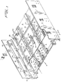
- Fig. 1 is a partial semi-exploded isometric view of a frame of a vibrating screening apparatus incorporating a preferred embodiment of the panel mounting system of the present invention;
- Fig. 2 is a fragmentary horizontal sectional view on an enlarged scale taken along lines 2-2 of Fig. 1;
- Fig. 3 is a fragmentary horizontal sectional view on a further enlarged scale showing a fastener of Fig. 2 with a locking member removed and the sides inwardly flexed for alternately receiving and releasing sides of laterally adjoining panels;
- Fig. 4 is a fragmentary plan view on the scale of Fig. 2 showing parts of longitudinally adjoining panels on a side of the frame and an interposed dam locked in operative position to both the frame's side plate and an adjacent fastener;
- Fig. 5 is a fragmentary vertical sectional view taken along lines 5-5 of Fig. 4; and
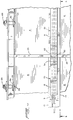
- Fig. 6 is a front elevational view on the scale of Figs. 2 and 4 showing the connections to a crosstube of the illustrated frame of fittings suitable for supporting the improved mounting system applied to vibrating screening apparatus.
- Rreferring now in detail to the drawings in which like reference characters designate like parts, the improved mounting system of the present invention, while adaptable for use in other screening apparatus, is particularly designed for mounting screen and other panels in vibrating screening apparatus and will be so described as exemplary of the invention.
- As pointed out in the "BACKGROUND" of Conn-Weld's Connolly et al U.S. patent No. 4,840,728, vibrating screening apparatus customarily has a frame formed of transversely spaced side frames or plates connected by cross-members and has between the side frames one or a plurality of vertically spaced decks or beds for mounting screen or other panels. While suitable for mounting panels in vibrating screening apparatus of various types, the panel mounting system of the present invention has been illustrated applied to the apparatus of the above Connolly patent.
- To the extent typical of vibrating screening apparatus, the Connolly apparatus is comprised of a frame 1 formed of parallel longitudinally extending transversely spaced
side plates 2 connected by laterally spacedcross-members 3, the latter, suitably in the form of cross-tubes, supporting a screen or other panel deck or bed 4. As in the Connolly apparatus, the panel deck 4 customarily includes a plurality of laterally spaced longitudinally extendinganchor members 5, each presenting as a web of an inverted channel or upper leg of an angle iron , an incrementally aperturedhorizontal surface 6. In conventional vibrating screening apparatus theanchor members 5 are welded to the frame 1, while in the Connolly apparatus they conveniently are channel parts of weldments U-bolt-and-saddle bolted to thecross-tubes 3. The use instead of welding of a bolted attachment in the Connolly apparatus also extends to any rubber-capped angle iron bucker bars 7 used to supportpanels 8 intermediate their sides. - Designed for enabling screen and
other panels 8 to be readily mounted in and as readily removed from vibrating screening apparatus, the panel mounting system of the present invention is comprised of elastomeric, preferably polyurethane, flexible-sided, longitudinal or longitudinally extending channel members or U-shaped fasteners, holders or hold-downs 9. Anchored to underlying incrementally aperturedanchor members 5, the channel members orU-shaped fasteners 9 are each interposed between laterally adjoiningpanels 8 and have in opposite sides orwings 10 longitudinally extending external grooves or seats 11 for receiving and seating correspondingly contoured, interfitting or mating edges orsides 12 of confronting edge members orborders 13 of adjacent panels. Whether theparticular panels 8 are nonporous or solid molded plastic or screen panels with profile or woven wire or molded plastic screening, theborders 13, as are the interposedfasteners 9, suitably are made of molded or extruded elastomeric material, such as and preferably polyurethane. - Normally parallel and laterally spaced and usually upright or outwardly projecting relative to its
base 14, the sides orwings 10 of eachfastener 9 and its base, together bound the sides and bottom of a longitudinally coterminous cavity orpocket 15 in the fastener. Suitably generally rectangular in cross-section, thecavity 15 in eachfastener 9 opens upwardly through a laterally concentric longitudinally coterminous relatively narrow or restrictedentry slot 16. Bolted or otherwise suitably anchored to the frame 1, eachfastener 9, for the illustrated incrementally apertured anchor orsupport member 5, conveniently has integral or rigid with or fixed or bonded to it, as correspondingly longitudinally spaced dependents or downward projections, a plurality of elastomeric, preferably polyurethane, frusto-conical anchoring pins 17. Axially bored or otherwise reduced in bulk for enhanced compressibility, theanchor pins 17 project through and have restrictednecks 18 suitably tightly fitting theapertures 19 in the anchor member. - Elastomeric and flexible-sided, the
sides 10 of eachfastener 9 in effect are hinged or hingedly attached at the bottom to the fastener'sbase 14. Thus, so long as itscavity 15 is empty or unoccupied, either one or both of the fastener'ssides 10 can yieldably deflect, flex, hinge, give or fold inwardly or toward each other. In that inwardly flexed condition of a fastener's side orsides 10, illustrated in the fragmentary vertical sectional view of Fig. 3, the edges or sides of either or both adjoiningpanels 8 are enabled readily to be engaged with or seated in and disengaged or unseated from the grooves or seats 11 in thesides 10 of thefastener 9. With the fasteners and not the panels anchored to the frame, installation and removal of a panel still requires the fasteners to be capable and readily of releasably locking a panel in place. - The above capability is derived from elastomeric, suitably polyurethane, T-shaped lock or
key members 20, each topped by a longitudinally elongatedflat strip 21, some of which strips, intermediate their ends, suitably have or are surmounted by upwardly projecting or extending protuberances, humps orsleeves 22 laterally or transversely slotted, apertured or through bored for slidably receiving and fastening end portions of dam sections ormodules 23. Eachlock member 20 has depending from its top strip 21 a downwardly bulged or enlarged upwardly necked stem ortongue 24. Depending on the lateral yieldability of thesides 10 of thefastener 9 in the area of theslot 16, the lock member's stem may itself be compressible for insertion through the slot and expandable in thecavity 15 or relatively or substantially hard or incompressible and dependent for insertion on lateral yieldability of thesides 10 of thefastener 9 in the area of the slot. In either case the lock member's enlarged stem, once inserted, substantially fills or equals the normal volumn of thecavity 15 in thefastener 9 and laterally forces, wedges or spreads thesides 10 to normal upright position, thereby locking sides of adjoining panels to confronting sides of the fastener and to the frame 1. Unlocking or releasing anindividual panel 8 from afastener 9 for repair or replacement is simply a matter of pulling or prying out of the fastener the stem ortongue 24 of any lock member involved in the locking and without disturbing the multi-pin or other anchoring of the fastener to theunderlying anchor member 5. - In the illustrated exemplary screening apparatus in which the
panels 8 are mounted three-abreast and four in tandem for a total of twelve, the side panels are half the width of the center panels and have their outer borders oredgings 13 supported onledges 25 bolted or otherwise fixed or attached to the insides of theside plates 2. With theirinner borders 13 releasably lockable to adjoiningfasteners 9, the outer borders of theside panels 8 are adapted to fit or be received in undercuts orrecesses 26 in longitudinally elongated clamping blocks orvise jaws 27, each attached as by bolting to and vertically adjustable on one of theside plates 2 above theledge 25 thereon for clamping theborder 13 of an adloining panel to the ledge. If, as suitable, theclamping blocks 27 are made of elastomeric or plastic material, they preferably are attached to theside plates 2 bycarriage bolts 23 projected throughretainer plates 29 embedded or recessed in the blocks and verticallyelongated slots 30 in the side plates. - In addition to locking them in place, it often is desirable to support
panels 8 midway of their sides. Two types of mid-supports are illustrated, one, the longitudinal rubber-capped angle iron bucker 7 of Fig. 5 and the other, thepolyurethane bucker strip 31 of Fig. 2. Particularly suited as a mid-support forwider panels 8, such as the center panel of Fig. 2, thebucker strip 31 suitably is flat and longitudinally extending, has a longitudinally coextensive raised center boss orridge 32, and, as are thefasteners 9, suitably is anchored to an underlying aperturedanchor member 5 by integral or rigidly attachedanchoring pins 17. - Longitudinally spaced relative to the
panels 8, thedam sections 23 are stepped at the bottoms of their end portions for fitting of their inner ends in the suitably rectangularly cross-sectionedlateral apertures 33 in thehumps 22 of thestrips 21 serving as dam section retainers and now designated as 34 to distinguish them from the other locking strips. Held or fastened to thefasteners 9 to which thepanel edges 12 are locked, theretainers 34 retain or anchor the inner ends of the dam sections ormodules 23 and the same function is performed adjacent the side plates by slotting or recessing theclamping blocks 27 for receiving and clamping the outer ends of the dam sections to theledges 25. - Ordinarily,
profile wire screens 35 have longitudinal wedge-shaped screen wires backed by and welded to transverse tie rods and the tie rods are coextensive in length with the overall width of the screen. However, in the system of the present invention, thetie rods 36 of profilewire screen panels 8 are used to strengthen the panel and particularly its bond or connection to its generally rectangularly cross-sectioned polyurethane edgings orborders 13 by extending the rod ends substantially uniformly into holes orapertures 37 in the confrontingsides 38 of the borders and making the holes longitudinally elongated or oval-shaped to compensate for manufacturing tolerances in the lateral spacing of the rods. The same result can be obtained with woven wire or polyurethane screen or solid panels by molding in or otherwise providing the panels with internal or external reinforcing rods and similarly extending the rods into the panel's borders. - From the above detailed description it will be apparent that there has been provided a system for mounting screen and other panels in vibrating and other screening apparatus in which the panels are not anchored to the frame of the apparatus and instead are releasably lockable at inner sides to flexible-sided fasteners and at outer sides, adjacent side plates of the apparatus, are releasably and adjustably clampable to the side plates.
- It should be understood that the described and disclosed embodiment is merely exemplary of the invention and that all modifications are intended to be included that do not depart from the spirit of the invention and the scope of the appended claims.
Claims (4)
- In a panel mounting system, a panel (8) releasably lockable to a frame (1) of vibrating screening apparatus by fastener means (9) anchored to said frame (1) and having sides (10) yieldably flexing toward each other for alternately engaging and disengaging a side of said panel (8), said panel (8) being bounded at sides by elastomeric borders (13) and presenting said borders (13) for engagement with and disengagement from sides (10) of said fastener means (9).
- A panel according to claim 1, wherein the elastomeric borders (13) bound sides of screening.
- A panel according to claim 2, wherein the screening is a profile wire screen (35) backed and reinforced by tie rods (36) extending across the screen (35) and embedded at ends in the borders (13).
- The system of claim 1, including longitudinally coterminous grooves (11) in said sides (10) of said fastener means (9), and longitudinally extending laterally projecting tongues (12) on said panel borders (13) conforming in contour to and seatable in said fastener grooves (11).
Applications Claiming Priority (3)
| Application Number | Priority Date | Filing Date | Title |
|---|---|---|---|
| US07/563,062 US5112475A (en) | 1990-08-06 | 1990-08-06 | Panel mounting system |
| US563062 | 1990-08-06 | ||
| EP91112244A EP0470422B1 (en) | 1990-08-06 | 1991-07-22 | Panel mounting system |
Related Parent Applications (2)
| Application Number | Title | Priority Date | Filing Date |
|---|---|---|---|
| EP91112244.8 Division | 1991-07-22 | ||
| EP91112244A Division EP0470422B1 (en) | 1990-08-06 | 1991-07-22 | Panel mounting system |
Publications (2)
| Publication Number | Publication Date |
|---|---|
| EP0699839A1 true EP0699839A1 (en) | 1996-03-06 |
| EP0699839B1 EP0699839B1 (en) | 2000-04-12 |
Family
ID=24248959
Family Applications (2)
| Application Number | Title | Priority Date | Filing Date |
|---|---|---|---|
| EP95114739A Expired - Lifetime EP0699839B1 (en) | 1990-08-06 | 1991-07-22 | Panel releasably lockable to a frame |
| EP91112244A Expired - Lifetime EP0470422B1 (en) | 1990-08-06 | 1991-07-22 | Panel mounting system |
Family Applications After (1)
| Application Number | Title | Priority Date | Filing Date |
|---|---|---|---|
| EP91112244A Expired - Lifetime EP0470422B1 (en) | 1990-08-06 | 1991-07-22 | Panel mounting system |
Country Status (7)
| Country | Link |
|---|---|
| US (1) | US5112475A (en) |
| EP (2) | EP0699839B1 (en) |
| JP (1) | JPH04227091A (en) |
| AU (1) | AU8112391A (en) |
| CA (1) | CA2035346C (en) |
| DE (2) | DE69132114T2 (en) |
| ZA (1) | ZA915735B (en) |
Cited By (3)
| Publication number | Priority date | Publication date | Assignee | Title |
|---|---|---|---|---|
| GB2312858A (en) * | 1996-05-10 | 1997-11-12 | William Myron Cravello | Shaker screen assembly |
| EP1946852A1 (en) * | 2007-01-17 | 2008-07-23 | Haver & Boecker oHG | Screening machine |
| AT524561B1 (en) * | 2021-07-30 | 2022-07-15 | Sbm Mineral Proc Gmbh | Screening device for screening bulk material |
Families Citing this family (44)
| Publication number | Priority date | Publication date | Assignee | Title |
|---|---|---|---|---|
| AU654091B2 (en) * | 1990-07-06 | 1994-10-20 | Lettela Proprietary Limited | Screen panel fixing system |
| US5277319A (en) * | 1990-08-06 | 1994-01-11 | Conn-Weld Industries, Inc. | Panel mounting system |
| US5213217A (en) * | 1991-10-25 | 1993-05-25 | Galton Zanley F | Screening system and method for screening particulate material |
| DE4141823C2 (en) * | 1991-12-18 | 1994-12-15 | Mann & Hummel Filter | Liquid filter |
| US5248043A (en) * | 1992-02-28 | 1993-09-28 | Dorn Lloyd A | Modular retro-fit screen system for a screening deck |
| FR2690489B1 (en) * | 1992-04-24 | 1994-12-23 | Giron Holding | System for attaching modular screening panels to a support structure. |
| US5392925A (en) * | 1993-08-12 | 1995-02-28 | Environmental Procedures, Inc. | Shale shaker and screen |
| ZA94452B (en) * | 1993-06-23 | 1994-09-02 | Screenex Wire Weaving Mfg Ltd | Screening arrangement |
| US5398817A (en) * | 1994-02-25 | 1995-03-21 | Conn-Weld Industries, Inc. | Center retainer assembly for panel mounting system |
| US5361911A (en) * | 1994-04-14 | 1994-11-08 | Miller Wire Works, Inc. | Screening panel attachment system |
| AUPM888594A0 (en) * | 1994-10-19 | 1994-11-10 | Lettela Proprietary Limited | Screen panel fixing system |
| US5586661A (en) * | 1994-12-15 | 1996-12-24 | Illinois Tool Works Inc. | Dam member for a screen deck |
| AUPN514395A0 (en) * | 1995-08-31 | 1995-09-21 | Lettela Proprietary Limited | Screening apparatus |
| US5816413A (en) * | 1995-09-08 | 1998-10-06 | W.S. Tyler, Canada | Wire screen deck having replaceable modular screen panels |
| US5755334A (en) * | 1996-03-19 | 1998-05-26 | Illinois Tool Works Inc. | Method and apparatus for mounting a panel on a support member |
| AU726837B2 (en) * | 1997-01-06 | 2000-11-23 | Lettela Proprietary Limited | Improved screen support system |
| DE19807162C2 (en) * | 1998-02-20 | 2001-05-23 | Isenmann Siebe Gmbh | Screening machine with sidebar |
| US6769550B2 (en) | 2002-01-16 | 2004-08-03 | Varco I/P, Inc. | Screen assemblies for shale shakers |
| US20050035033A1 (en) * | 1999-03-25 | 2005-02-17 | Adams Thomas C. | Methods for sealing screen assemblies on vibratory separators |
| WO2002074454A1 (en) * | 2001-03-19 | 2002-09-26 | Ludwig Krieger Draht- Und Kunststofferzeugnisse Gmbh | Screening panel and screening machine fitted with same |
| US6957741B2 (en) * | 2001-08-07 | 2005-10-25 | Manfred Franz Axel Freissle | Screening arrangement |
| US20050103689A1 (en) * | 2001-10-19 | 2005-05-19 | Schulte David L.Jr. | Sealing screen assemblies and vibratory separators |
| US20050224398A1 (en) * | 2001-10-19 | 2005-10-13 | Largent David W | Vibratory separators and sealing screens |
| US20050067327A1 (en) * | 2002-01-16 | 2005-03-31 | Adams Thomas C. | Screen assemblies for shale shakers |
| WO2003066243A1 (en) * | 2002-02-11 | 2003-08-14 | Multotec Manufacturing (Pty) Limited | Screen deck |
| US6964341B2 (en) * | 2004-01-30 | 2005-11-15 | Conn-Weld Industries, Inc. | Screen panel retainer system |
| SE530929C2 (en) * | 2007-04-19 | 2008-10-21 | Sandvik Intellectual Property | Support structure for a vibration layer and a support carrier thereof |
| US7717269B2 (en) * | 2007-05-15 | 2010-05-18 | Conn-Weld Industries, Inc. | Snap lock separatory panel and retainer system |
| US7946428B1 (en) | 2008-07-11 | 2011-05-24 | Conn-Weld Industries, Inc. | Screen panel center retainer system |
| US8376143B2 (en) * | 2008-07-11 | 2013-02-19 | Conn-Weld Industries, Inc. | Screen panel center retainer system |
| US8887922B2 (en) * | 2010-04-12 | 2014-11-18 | Norris Screen And Manufacturing, Llc | Screen deck assembly |
| USD628717S1 (en) * | 2010-06-14 | 2010-12-07 | Dirtt Environmental Solutions, Ltd. | Disc-shaped interface member for architectural divider assemblies |
| US8281934B1 (en) | 2011-03-16 | 2012-10-09 | Conn-Weld Industries, Inc. | Screen panel retainer system |
| US9186703B2 (en) | 2012-09-27 | 2015-11-17 | Conn-Weld Industries, Inc. | Locking twist pin screen panel retainer |
| WO2014177910A1 (en) * | 2013-04-30 | 2014-11-06 | Flsmidth A/S | Vibrating screen |
| WO2015106305A1 (en) * | 2014-01-15 | 2015-07-23 | Schenck Process Australia Pty Ltd | Ore screening panel fixing system |
| US10123486B2 (en) * | 2015-07-23 | 2018-11-13 | Cnh Industrial America Llc | Frame for agricultural harvester cleaner |
| US10315226B2 (en) * | 2015-09-21 | 2019-06-11 | Polydeck Screen Corporation | Screening system for portable vibratory machine |
| US10900514B2 (en) | 2017-11-07 | 2021-01-26 | Hellermanntyton Corporation | Wire-tray-assembly with stud-mount inserts |
| CN109780026A (en) * | 2017-11-15 | 2019-05-21 | 青岛海尔洗衣机有限公司 | A connection structure, a washing machine panel locking device and a washing machine |
| CN109837707B (en) * | 2017-11-27 | 2022-09-06 | 青岛海尔洗涤电器有限公司 | Washing machine table-board fixing structure and washing machine |
| CN112253585A (en) * | 2020-10-19 | 2021-01-22 | 北京蓝科盈晟航空科技有限公司 | Fastening device of rocket engine shell mold with large length-diameter ratio and preparation process |
| US11451025B2 (en) | 2020-12-22 | 2022-09-20 | Hellermann Tyton Corporation | Wire tray and mounting insert assemblies |
| AT525173B1 (en) * | 2022-04-12 | 2023-01-15 | Sbm Mineral Proc Gmbh | screening device |
Citations (7)
| Publication number | Priority date | Publication date | Assignee | Title |
|---|---|---|---|---|
| DE1251087B (en) * | 1958-01-21 | |||
| US3980555A (en) | 1973-08-24 | 1976-09-14 | Screenex Wire Weaving Manufacturers Limited | Replacable screen with frame |
| AT345211B (en) * | 1977-02-15 | 1978-09-11 | Hutter & Schrantz Ag | FASTENING A SCREEN BASE |
| US4141821A (en) | 1976-05-21 | 1979-02-27 | Firma Steinhaus Gmbh | Screening deck assembly |
| US4675937A (en) * | 1985-02-14 | 1987-06-30 | Nifco, Inc. | Resilient grommet with metal lock plate |
| DE3607660A1 (en) * | 1986-03-08 | 1987-09-10 | Schade Maschf Gustav | PERFORATED PLATE FASTENING ON A SUB-CONSTRUCTION, ESPECIALLY FOR SCREENING MACHINES |
| US4840728A (en) | 1988-03-14 | 1989-06-20 | Conn-Weld Industries, Inc. | Vibrating screening apparatus |
Family Cites Families (15)
| Publication number | Priority date | Publication date | Assignee | Title |
|---|---|---|---|---|
| DE1008257B (en) * | 1953-09-03 | 1957-05-16 | Gustav Netzel Dipl Ing | Attachment of separating agents and their support agents on filters, sieves, etc. like |
| FR1566814A (en) * | 1967-04-27 | 1969-05-09 | ||
| CA855914A (en) * | 1968-02-23 | 1970-11-17 | A. Mackenzie James | Releasable reusable expanding fastener |
| US3665666A (en) * | 1970-12-03 | 1972-05-30 | Andre Delcroix | Devices for interconnecting plates |
| AT344630B (en) * | 1976-11-26 | 1978-08-10 | Binder Co Ag | SCREEN PLATE ATTACHMENT |
| DE2754044B1 (en) * | 1977-12-05 | 1979-04-19 | Willi-Klaus Kinker | Industrial sieve bottom for processing bulk goods |
| DE3008931A1 (en) * | 1980-03-08 | 1981-09-17 | Hein, Lehmann AG, 4000 Düsseldorf | SYSTEM SCREEN |
| DE3307916A1 (en) * | 1983-03-05 | 1984-09-06 | Hein, Lehmann AG, 4000 Düsseldorf | SCREEN COVER WITH INTERCHANGEABLE SCREEN ELEMENTS |
| DE3425485A1 (en) * | 1984-07-11 | 1986-01-16 | Hein, Lehmann AG, 4000 Düsseldorf | SCREENING |
| FR2574007A1 (en) * | 1984-12-03 | 1986-06-06 | Tera Sarl | Device for the detachable fixing of elements for screening and for shoring up, and elements of this type |
| US4757664A (en) * | 1985-06-04 | 1988-07-19 | Screenex Wire Weaving Manufacturers (Proprietary) Limited | Wear resistant panel arrangement |
| US4603528A (en) * | 1985-07-02 | 1986-08-05 | Venturetech Enterprises, Inc. | Panel installation |
| EP0236530B1 (en) * | 1986-03-13 | 1989-10-18 | Hein, Lehmann Aktiengesellschaft | Screen bottom |
| US4909929A (en) * | 1988-10-24 | 1990-03-20 | Norris Screen & Manufacturing, Inc. | Interlocking clamping system |
| US4936065A (en) * | 1989-01-17 | 1990-06-26 | Dunmon Corporation | Non-foldable composite attachment system |
-
1990
- 1990-08-06 US US07/563,062 patent/US5112475A/en not_active Expired - Lifetime
-
1991
- 1991-01-31 CA CA002035346A patent/CA2035346C/en not_active Expired - Lifetime
- 1991-07-18 AU AU81123/91A patent/AU8112391A/en not_active Abandoned
- 1991-07-22 DE DE69132114T patent/DE69132114T2/en not_active Expired - Fee Related
- 1991-07-22 EP EP95114739A patent/EP0699839B1/en not_active Expired - Lifetime
- 1991-07-22 DE DE69118272T patent/DE69118272T2/en not_active Expired - Fee Related
- 1991-07-22 EP EP91112244A patent/EP0470422B1/en not_active Expired - Lifetime
- 1991-07-22 ZA ZA915735A patent/ZA915735B/en unknown
- 1991-08-02 JP JP3194285A patent/JPH04227091A/en active Pending
Patent Citations (7)
| Publication number | Priority date | Publication date | Assignee | Title |
|---|---|---|---|---|
| DE1251087B (en) * | 1958-01-21 | |||
| US3980555A (en) | 1973-08-24 | 1976-09-14 | Screenex Wire Weaving Manufacturers Limited | Replacable screen with frame |
| US4141821A (en) | 1976-05-21 | 1979-02-27 | Firma Steinhaus Gmbh | Screening deck assembly |
| AT345211B (en) * | 1977-02-15 | 1978-09-11 | Hutter & Schrantz Ag | FASTENING A SCREEN BASE |
| US4675937A (en) * | 1985-02-14 | 1987-06-30 | Nifco, Inc. | Resilient grommet with metal lock plate |
| DE3607660A1 (en) * | 1986-03-08 | 1987-09-10 | Schade Maschf Gustav | PERFORATED PLATE FASTENING ON A SUB-CONSTRUCTION, ESPECIALLY FOR SCREENING MACHINES |
| US4840728A (en) | 1988-03-14 | 1989-06-20 | Conn-Weld Industries, Inc. | Vibrating screening apparatus |
Cited By (7)
| Publication number | Priority date | Publication date | Assignee | Title |
|---|---|---|---|---|
| GB2312858A (en) * | 1996-05-10 | 1997-11-12 | William Myron Cravello | Shaker screen assembly |
| GB2312858B (en) * | 1996-05-10 | 2000-03-22 | William Myron Cravello | Shaker screen assembly |
| EP1946852A1 (en) * | 2007-01-17 | 2008-07-23 | Haver & Boecker oHG | Screening machine |
| US7770737B2 (en) | 2007-01-17 | 2010-08-10 | Haver & Boecker Ohg | Screening machine |
| AT524561B1 (en) * | 2021-07-30 | 2022-07-15 | Sbm Mineral Proc Gmbh | Screening device for screening bulk material |
| AT524561A4 (en) * | 2021-07-30 | 2022-07-15 | Sbm Mineral Proc Gmbh | Screening device for screening bulk material |
| EP4124392A1 (en) | 2021-07-30 | 2023-02-01 | SBM Mineral Processing GmbH | Screening device for screening bulk material |
Also Published As
| Publication number | Publication date |
|---|---|
| CA2035346C (en) | 2002-04-16 |
| EP0470422A2 (en) | 1992-02-12 |
| EP0699839B1 (en) | 2000-04-12 |
| JPH04227091A (en) | 1992-08-17 |
| CA2035346A1 (en) | 1992-02-07 |
| EP0470422B1 (en) | 1996-03-27 |
| DE69132114T2 (en) | 2000-09-28 |
| AU8112391A (en) | 1992-02-13 |
| EP0470422A3 (en) | 1992-09-02 |
| ZA915735B (en) | 1992-06-24 |
| DE69118272T2 (en) | 1996-08-29 |
| DE69132114D1 (en) | 2000-05-18 |
| DE69118272D1 (en) | 1996-05-02 |
| US5112475A (en) | 1992-05-12 |
Similar Documents
| Publication | Publication Date | Title |
|---|---|---|
| EP0470422B1 (en) | Panel mounting system | |
| US5277319A (en) | Panel mounting system | |
| US5346053A (en) | Modular screen system for screening deck | |
| US5829599A (en) | Screening apparatus | |
| US5755334A (en) | Method and apparatus for mounting a panel on a support member | |
| US6253926B1 (en) | Modular screen panel | |
| US5207262A (en) | Tonneau cover system | |
| US4909929A (en) | Interlocking clamping system | |
| US5377846A (en) | Particle screening system | |
| CA2137751A1 (en) | Screening panel attachment system | |
| EP2528477B1 (en) | Seating furniture | |
| US5769241A (en) | Screen panel fixing system | |
| US5104521A (en) | Modular tensioned screen surfaces | |
| CA2943549C (en) | Screen panel locking system | |
| US3295805A (en) | Support structure and connection between a structure and a fixture | |
| CA2920437C (en) | Screen panel locking system | |
| AU704990B3 (en) | Particle screening system | |
| AU2016200857B2 (en) | Screen panel locking system | |
| AU2003204125B2 (en) | Ore Screening Panel Fixing System | |
| AU770350B2 (en) | Modular screening system | |
| AU729679B2 (en) | Particle screening system | |
| AU2002221329B2 (en) | Modular screen panel | |
| AU4116099A (en) | Screen deck module | |
| AU1752300A (en) | Ore screening panel system | |
| EP1950083A1 (en) | Seating arrangement |
Legal Events
| Date | Code | Title | Description |
|---|---|---|---|
| PUAI | Public reference made under article 153(3) epc to a published international application that has entered the european phase |
Free format text: ORIGINAL CODE: 0009012 |
|
| AC | Divisional application: reference to earlier application |
Ref document number: 470422 Country of ref document: EP |
|
| AK | Designated contracting states |
Kind code of ref document: A1 Designated state(s): BE DE FR GB NL SE |
|
| 17P | Request for examination filed |
Effective date: 19960826 |
|
| 17Q | First examination report despatched |
Effective date: 19970612 |
|
| GRAG | Despatch of communication of intention to grant |
Free format text: ORIGINAL CODE: EPIDOS AGRA |
|
| GRAG | Despatch of communication of intention to grant |
Free format text: ORIGINAL CODE: EPIDOS AGRA |
|
| GRAH | Despatch of communication of intention to grant a patent |
Free format text: ORIGINAL CODE: EPIDOS IGRA |
|
| GRAH | Despatch of communication of intention to grant a patent |
Free format text: ORIGINAL CODE: EPIDOS IGRA |
|
| GRAA | (expected) grant |
Free format text: ORIGINAL CODE: 0009210 |
|
| AC | Divisional application: reference to earlier application |
Ref document number: 470422 Country of ref document: EP |
|
| AK | Designated contracting states |
Kind code of ref document: B1 Designated state(s): BE DE FR GB NL SE |
|
| REF | Corresponds to: |
Ref document number: 69132114 Country of ref document: DE Date of ref document: 20000518 |
|
| ET | Fr: translation filed | ||
| PLBE | No opposition filed within time limit |
Free format text: ORIGINAL CODE: 0009261 |
|
| STAA | Information on the status of an ep patent application or granted ep patent |
Free format text: STATUS: NO OPPOSITION FILED WITHIN TIME LIMIT |
|
| 26N | No opposition filed | ||
| REG | Reference to a national code |
Ref country code: GB Ref legal event code: IF02 |
|
| PGFP | Annual fee paid to national office [announced via postgrant information from national office to epo] |
Ref country code: SE Payment date: 20020705 Year of fee payment: 12 |
|
| PGFP | Annual fee paid to national office [announced via postgrant information from national office to epo] |
Ref country code: FR Payment date: 20020709 Year of fee payment: 12 |
|
| PGFP | Annual fee paid to national office [announced via postgrant information from national office to epo] |
Ref country code: GB Payment date: 20020717 Year of fee payment: 12 |
|
| PGFP | Annual fee paid to national office [announced via postgrant information from national office to epo] |
Ref country code: NL Payment date: 20020730 Year of fee payment: 12 |
|
| PGFP | Annual fee paid to national office [announced via postgrant information from national office to epo] |
Ref country code: DE Payment date: 20020731 Year of fee payment: 12 |
|
| PGFP | Annual fee paid to national office [announced via postgrant information from national office to epo] |
Ref country code: BE Payment date: 20020919 Year of fee payment: 12 |
|
| PG25 | Lapsed in a contracting state [announced via postgrant information from national office to epo] |
Ref country code: GB Free format text: LAPSE BECAUSE OF NON-PAYMENT OF DUE FEES Effective date: 20030722 |
|
| PG25 | Lapsed in a contracting state [announced via postgrant information from national office to epo] |
Ref country code: SE Free format text: LAPSE BECAUSE OF NON-PAYMENT OF DUE FEES Effective date: 20030723 |
|
| PG25 | Lapsed in a contracting state [announced via postgrant information from national office to epo] |
Ref country code: BE Free format text: LAPSE BECAUSE OF NON-PAYMENT OF DUE FEES Effective date: 20030731 |
|
| BERE | Be: lapsed |
Owner name: *CONN-WELD INDUSTRIES INC. Effective date: 20030731 |
|
| PG25 | Lapsed in a contracting state [announced via postgrant information from national office to epo] |
Ref country code: NL Free format text: LAPSE BECAUSE OF NON-PAYMENT OF DUE FEES Effective date: 20040201 |
|
| PG25 | Lapsed in a contracting state [announced via postgrant information from national office to epo] |
Ref country code: DE Free format text: LAPSE BECAUSE OF NON-PAYMENT OF DUE FEES Effective date: 20040203 |
|
| EUG | Se: european patent has lapsed | ||
| GBPC | Gb: european patent ceased through non-payment of renewal fee |
Effective date: 20030722 |
|
| PG25 | Lapsed in a contracting state [announced via postgrant information from national office to epo] |
Ref country code: FR Free format text: LAPSE BECAUSE OF NON-PAYMENT OF DUE FEES Effective date: 20040331 |
|
| NLV4 | Nl: lapsed or anulled due to non-payment of the annual fee |
Effective date: 20040201 |
|
| REG | Reference to a national code |
Ref country code: FR Ref legal event code: ST |