EP0699083B1 - Medical gas insufflator with automatic gas flow control - Google Patents
Medical gas insufflator with automatic gas flow control Download PDFInfo
- Publication number
- EP0699083B1 EP0699083B1 EP95910593A EP95910593A EP0699083B1 EP 0699083 B1 EP0699083 B1 EP 0699083B1 EP 95910593 A EP95910593 A EP 95910593A EP 95910593 A EP95910593 A EP 95910593A EP 0699083 B1 EP0699083 B1 EP 0699083B1
- Authority
- EP
- European Patent Office
- Prior art keywords
- pressure
- insufflation
- flow rate
- gas
- gas flow
- Prior art date
- Legal status (The legal status is an assumption and is not a legal conclusion. Google has not performed a legal analysis and makes no representation as to the accuracy of the status listed.)
- Expired - Lifetime
Links
- 230000007935 neutral effect Effects 0.000 claims abstract description 11
- 238000011144 upstream manufacturing Methods 0.000 claims abstract description 11
- 239000007789 gas Substances 0.000 claims description 77
- 230000033228 biological regulation Effects 0.000 claims description 21
- 238000005259 measurement Methods 0.000 claims description 17
- 238000002347 injection Methods 0.000 claims description 10
- 239000007924 injection Substances 0.000 claims description 10
- 230000003068 static effect Effects 0.000 claims description 8
- 238000004364 calculation method Methods 0.000 claims description 7
- 238000009530 blood pressure measurement Methods 0.000 claims description 6
- 238000010438 heat treatment Methods 0.000 claims description 6
- 238000001839 endoscopy Methods 0.000 claims description 5
- 230000009467 reduction Effects 0.000 claims description 5
- 238000011156 evaluation Methods 0.000 claims description 4
- 239000003517 fume Substances 0.000 claims description 4
- 238000000034 method Methods 0.000 claims description 4
- 238000012423 maintenance Methods 0.000 claims description 3
- 230000008569 process Effects 0.000 claims description 3
- 239000007788 liquid Substances 0.000 claims description 2
- 230000006835 compression Effects 0.000 claims 1
- 238000007906 compression Methods 0.000 claims 1
- 238000012886 linear function Methods 0.000 claims 1
- CURLTUGMZLYLDI-UHFFFAOYSA-N Carbon dioxide Chemical compound O=C=O CURLTUGMZLYLDI-UHFFFAOYSA-N 0.000 description 16
- 229910002092 carbon dioxide Inorganic materials 0.000 description 8
- 210000000683 abdominal cavity Anatomy 0.000 description 4
- 238000007664 blowing Methods 0.000 description 4
- 239000001569 carbon dioxide Substances 0.000 description 4
- 238000010586 diagram Methods 0.000 description 4
- 239000000779 smoke Substances 0.000 description 4
- 238000010521 absorption reaction Methods 0.000 description 3
- 230000009471 action Effects 0.000 description 3
- 230000000694 effects Effects 0.000 description 3
- 239000000543 intermediate Substances 0.000 description 3
- 238000012986 modification Methods 0.000 description 3
- 230000004048 modification Effects 0.000 description 3
- 238000001356 surgical procedure Methods 0.000 description 3
- 206010002091 Anaesthesia Diseases 0.000 description 2
- 230000037005 anaesthesia Effects 0.000 description 2
- 230000036760 body temperature Effects 0.000 description 2
- 230000008859 change Effects 0.000 description 2
- 235000021183 entrée Nutrition 0.000 description 2
- 230000001105 regulatory effect Effects 0.000 description 2
- 238000012360 testing method Methods 0.000 description 2
- 230000001052 transient effect Effects 0.000 description 2
- 238000009423 ventilation Methods 0.000 description 2
- 208000031968 Cadaver Diseases 0.000 description 1
- 241000282461 Canis lupus Species 0.000 description 1
- 241001465754 Metazoa Species 0.000 description 1
- 241001080024 Telles Species 0.000 description 1
- 230000003187 abdominal effect Effects 0.000 description 1
- 230000004913 activation Effects 0.000 description 1
- 230000001464 adherent effect Effects 0.000 description 1
- 230000004872 arterial blood pressure Effects 0.000 description 1
- 230000008901 benefit Effects 0.000 description 1
- 210000004204 blood vessel Anatomy 0.000 description 1
- 230000007211 cardiovascular event Effects 0.000 description 1
- 238000001816 cooling Methods 0.000 description 1
- 239000000112 cooling gas Substances 0.000 description 1
- 125000004122 cyclic group Chemical group 0.000 description 1
- 230000007423 decrease Effects 0.000 description 1
- 238000000151 deposition Methods 0.000 description 1
- 238000001514 detection method Methods 0.000 description 1
- 238000011161 development Methods 0.000 description 1
- 238000006073 displacement reaction Methods 0.000 description 1
- 238000002474 experimental method Methods 0.000 description 1
- 239000000835 fiber Substances 0.000 description 1
- 238000002513 implantation Methods 0.000 description 1
- 230000036512 infertility Effects 0.000 description 1
- 230000000977 initiatory effect Effects 0.000 description 1
- 230000000968 intestinal effect Effects 0.000 description 1
- 230000002045 lasting effect Effects 0.000 description 1
- 208000030159 metabolic disease Diseases 0.000 description 1
- 210000004303 peritoneum Anatomy 0.000 description 1
- 230000000750 progressive effect Effects 0.000 description 1
- 230000000284 resting effect Effects 0.000 description 1
- 230000000630 rising effect Effects 0.000 description 1
- 239000003381 stabilizer Substances 0.000 description 1
- 230000003797 telogen phase Effects 0.000 description 1
- 230000001225 therapeutic effect Effects 0.000 description 1
Images


Classifications
-
- A—HUMAN NECESSITIES
- A61—MEDICAL OR VETERINARY SCIENCE; HYGIENE
- A61M—DEVICES FOR INTRODUCING MEDIA INTO, OR ONTO, THE BODY; DEVICES FOR TRANSDUCING BODY MEDIA OR FOR TAKING MEDIA FROM THE BODY; DEVICES FOR PRODUCING OR ENDING SLEEP OR STUPOR
- A61M13/00—Insufflators for therapeutic or disinfectant purposes, i.e. devices for blowing a gas, powder or vapour into the body
- A61M13/003—Blowing gases other than for carrying powders, e.g. for inflating, dilating or rinsing
-
- A—HUMAN NECESSITIES
- A61—MEDICAL OR VETERINARY SCIENCE; HYGIENE
- A61M—DEVICES FOR INTRODUCING MEDIA INTO, OR ONTO, THE BODY; DEVICES FOR TRANSDUCING BODY MEDIA OR FOR TAKING MEDIA FROM THE BODY; DEVICES FOR PRODUCING OR ENDING SLEEP OR STUPOR
- A61M2202/00—Special media to be introduced, removed or treated
- A61M2202/02—Gases
- A61M2202/0225—Carbon oxides, e.g. Carbon dioxide
-
- A—HUMAN NECESSITIES
- A61—MEDICAL OR VETERINARY SCIENCE; HYGIENE
- A61M—DEVICES FOR INTRODUCING MEDIA INTO, OR ONTO, THE BODY; DEVICES FOR TRANSDUCING BODY MEDIA OR FOR TAKING MEDIA FROM THE BODY; DEVICES FOR PRODUCING OR ENDING SLEEP OR STUPOR
- A61M2205/00—General characteristics of the apparatus
- A61M2205/33—Controlling, regulating or measuring
- A61M2205/3331—Pressure; Flow
- A61M2205/3344—Measuring or controlling pressure at the body treatment site
Definitions
- the present invention relates to a resuscitator medical with automatic gas flow regulation, used in the field of diagnostic endoscopy and surgical to create inside the human body or animal, by blowing a neutral gas, a cavity of observation and / or an operating space.
- the systems offered generally combine a measuring device, gas expansion means blown with one or more tanks intermediates, and automatic flow regulation gaseous.
- Document DE-A-25 44 467 (WOLF Richard GmbH) describes a device for introducing into the cavity abdominal carbon dioxide CO2 contained in a tank under pressure using a pressure regulator, a channel insufflation controlled by a solenoid valve, and a channel measuring the opening of said solenoid valve. This device also requires two Veress needles insufflation or a two-way Veress needle.
- Document DE-A-28 03 646 (SEMM Kurt) concerns a device for introducing gas into the abdominal cavity carbon dioxide CO2, using a multi-stage assembly comprising several regulators and tanks intermediates, characterized by a bypass system flow control multichannels. As realized, this device is supplemented by other arrangements, described in the following documents.
- document DE-A-34 13 631 (SEMM Kurt) reveals a device for calculating pressure intracavitary from the velocity of flow, the resistance to flow and pressure insufflation.
- the invention has essentially for a medical resuscitator to automatic gas flow control, including a insufflation circuit of a neutral gas in a cavity operating, in relation to a gas source under pressure, and on this circuit a valve controlled by flow regulation, the insufflator being characterized by what it includes means of pressure measurement at the head of the insufflation circuit, means for continuously calculating pressure intercavity from insufflation pressure, this through an assessment of the loss of circuit load, means of comparison between the calculated intracavity pressure and a setpoint of this intracavitary pressure, and means of control of the flow control valve according to the result of comparison with setpoint above, in order to continuously supply a gas flow minimal neutral to strictly compensate for leaks gas out of the operating cavity.
- a device which returns permanently calculated intracavitary pressure, very close to the actual intracavity pressure (less than 2% difference), and which, by the use of a flow control, in particular a proportional valve, whose opening is electronically controlled, maintains intracavity pressure at the set point in reducing the flow rates and insufflation pressures to the strict necessary, this by strictly compensating for leaks from gas, which induces a reduction in the limit pressure insufflation to a level compatible with the safety of patients.
- the device momentarily compensates for these losses by adjusting the flow rates and insufflation pressures as well as the maximum pressure insufflation (safety threshold).
- the proposed device adapts instantly to all practical circuit configurations (tubes, needles insufflation or trocards, ...) and any modifications conditions of use (bent or pinched tube, ).
- the pneumatic control assembly has the advantage of a very large compactness. It also allows flow measurement instantaneous, by measuring the pressure drop between the two ends of the capillary, thanks to a sensor pressure differential as specified below.
- this device achieving adiabatic relaxation gas causes, if not remedied, significant cooling of the gas, especially at high flow rates, and blowing too cold gas can cause the patient of significant incidents, especially since during anesthesia the body temperature is no longer properly regulated.
- the flow measurement being determined by measuring the pressure drop between the ends of the capillary it is necessary to maintain this one at constant temperature in order to achieve a precise measurement.
- the regulation assembly tire is advantageously supplemented by means of temperature maintenance of all of its components, ensuring in particular the heating of the gas passing through the capillary up to a temperature of the order of body, or in practice a temperature between 35 ° C and 40 ° C.
- the subassembly comprising the capillary of trigger and the differential pressure sensor is made up of two coaxial cylindrical elements, mounted one inside the other, the capillary being constituted by an annular section free space between the two cylindrical elements, while two sockets pressure are provided in the cylindrical element outside, respectively upstream and downstream of the area forming a capillary, to supply the differential sensor pressure from which the flow rate is determined gas snapshot.
- the inlet safety valve can also be incorporated into this subset, especially in center of the inner cylindrical member.
- the insufflation flow remains constant during each cycle. However, this flow varies, by jumps, from one cycle to another, to allow by successive steps (progressive opening or closing of flow control valve) to strictly compensate gas leaks in order to maintain or reach the setpoint inter-cavity pressure.
- FIG. 2 illustrates the configuration as a function of the difference ⁇ P between the set pressure and the static or inter-cavity pressure (expressed in mm Hg), the corresponding flow jump ⁇ D 'being expressed in l / min.
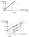
- Figure 3 illustrates the configuration as a function of the deviation ⁇ (P setpoint - P intracavitary) expressing the ability to compensate for leaks, in the same system of units.
- the insufflation pressure measured downstream of the pneumatic assembly as indicated above, is preferably voluntarily limited to a maximum threshold so reduce the risk of cardiovascular events for the patient.
- this threshold called also safety pressure
- the safety pressure is modulated according to the debit.
- the safety pressure is modulated according to a function increasing linear flow, up to a value particular flow rate, and above this value of flow, said safety pressure is constant from so as to set an absolute limit to the pressure insufflation.
- the diagram in Figure 4 illustrates, in the case of an example, such a law of variation of the safety pressure.
- the device operates in a cyclic mode (cycle from 2 to 3 seconds for example), all parameters such as defined above being recalculated for each cycle. After each rest phase, the device restarts at the rate minimal.
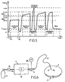
- Figure 5 is a pressure diagram during a flow increase cycle, illustrating the times successive insufflation with separate flows, until the set pressure is reached, a insufflation shutdown being carried out at an instant intermediate where the safety pressure pmax is reached.
- Figure 6 is a block diagram showing a medical resuscitator and its environment
- Figure 7 is a block diagram of the medical insufflator according to the present invention.
- Figure 8 is a detail view, in section, of a particular embodiment of the capillary duct to which is associated with the differential pressure sensor.
- the medical insufflator designated overall by the mark 1 on figure 6, insufflates a gas neutral, such as carbon dioxide CO2, in a cavity operating room 2 of a patient 3.
- a gas neutral such as carbon dioxide CO2
- Gas blowing into the operating cavity 2 is carried out from device 1 by through a circuit comprising an output 4 of gas, a flexible connection tube 5 and a needle Veress 6.
- the gas is kept in reserve, at high pressure (by example 49 bars) and in liquefied form, in a bottle 7 at the outlet of which a regulator is provided primary 8 for reducing the gas pressure to a calibrated and rigorously constant low pressure, by example of three bars.
- a differential pressure sensor 17 is associated with the relaxation capillary.
- Another sensor pressure 18, placed on outlet 4 to the circuit insufflation allows to determine the insufflation pressure Pi by direct measurement.
- the intracavitary pressure Pa is deduced, by calculation, from the measurement of the insufflation pressure Pi and the evaluation of the pressure drop in the insufflation circuit.
- the capillary of trigger 11 made from two cylindrical elements 19 and 20, arranged coaxially one inside the other.
- the first cylindrical element 19, or external element has a gas inlet 21 at one end, and there contains the filter 9.
- the second cylindrical element 20, or inner element carries the valve in its center entry security 10. Between the two cylindrical elements 19 and 20 extends an annular space, the thickness of which (measured radially) is for example 0.16 mm, and which constitutes the capillary duct 11.
- the gas outlet takes place laterally at 22, through a hole drilled in the wall of the first cylindrical element 19, downstream of the capillary duct 11 of annular section.
- the differential pressure sensor 17 uses a first lateral pressure tap 23, in the form of a hole drilled in the wall of the first cylindrical element 19 upstream of the capillary duct 11 of annular section, and a second lateral pressure tap 24, under the form of another hole drilled in the wall of the first cylindrical element 19 downstream of the capillary duct 11.
- the two pressure sensors 17 and 18 are connected to an electronic measurement and control unit 25, which controls the flow control valve 13 according to the enslavement procedures described above, in particular to maintain the intracavitary pressure Pa at the value setpoint, while limiting the blowing pressure Pi at the desired safety threshold value.
- a non-return valve 26 equipping the departure of the insufflation circuit avoids any pollution of the device by rising liquids or fumes, while the compensation of overpressures by suction on the same connecting tube 5 than that intended for insufflation of the gas in the operating cavity 2 is in itself a cause certain of pollution.
- This check valve 26 is associated with a Y connector 27 located at the start of the connection 5, and used to connect a tube bypass 28 with smoke filter 29, ensuring the escape of overpressures to the outside while preventing the rejection of harmful fumes (laser for example) in the atmosphere of the operating room.
- the pneumatic cylinder 31 of the crushing device or pinch of tube 30 can be ordered either automatic in the event of overpressure detection, by via an exhaust solenoid valve 32 controlled by the calculated intracavitary pressure, i.e. manually to allow the evacuation of smoke.
- an exhaust solenoid valve 32 controlled by the calculated intracavitary pressure, i.e. manually to allow the evacuation of smoke.
- no measurement of pressure is not carried out because the sensor 18 could not measure that the exhaust pressure, close to the ambient pressure.
- This device must only act for lasting overpressures; its automatic mode of action is so on the one hand timed, so as not to take into has some sporadic effects due for example to introduction of instruments by the surgeon, and others share limited to equal intracavitary pressures or higher than the set pressure increased by one predetermined value.
- the device which is the subject of the invention also makes it possible to execute a particular cycle of checking the correct implantation of the needle, before insufflation.
- endoscopy practitioners have the habit of injecting, before insufflation, a small volume of air (of the order of 20 cm 3 ) using a syringe through insufflation needle, to make sure that it does not open into a blood vessel or between the sheets of the peritoneum.
- Intra-abdominal pressure is normally a little below ambient atmospheric pressure, the injection of 20 cm 3 of air into a cavity representing more than 10 dm 3 does not cause a significant change in intra-abdominal pressure ; this effect is complemented by the absorption of gas by the entire peritoneal surface. If the needle has not reached the abdominal cavity, if it is implanted between two peritoneal or adherent sheets, or stuck in an intestinal loop, the injection of 20 cm 3 of air will cause a variation in the gas pressure in the cavity where the injection takes place, and the plunger of the syringe will allow some "elastic" re-aspiration.
- this manual test is replaced by a test authorizing or not the activation of the insufflator.
- a particular command of the device automatically triggers the injection of a predetermined and small quantity, for example 20 cm 3 of gas at the minimum flow rate, ie 1 l / min.
- a measurement of the static (intra-abdominal) pressure is carried out before the injection.
- a second measurement is made after this injection. If the two measurements differ by a difference greater than a certain tolerance threshold, the device is put back on hold, and it emits an alarm signal.
- the heating member 12 such that electrical heating resistance, allows not only to keep the gas at constant temperature in the capillary 11 for measuring the gas flow by through the differential pressure sensor 17, but also ensures the heating of this gas (cooled by trigger) to a temperature compatible with that of the body, between 35 ° C and 40 ° C, and preferably between 38 ° C and 40 ° C, before insufflation in the abdominal cavity or other operating cavity.
Landscapes
- Health & Medical Sciences (AREA)
- Life Sciences & Earth Sciences (AREA)
- General Health & Medical Sciences (AREA)
- Biomedical Technology (AREA)
- Heart & Thoracic Surgery (AREA)
- Hematology (AREA)
- Engineering & Computer Science (AREA)
- Animal Behavior & Ethology (AREA)
- Anesthesiology (AREA)
- Public Health (AREA)
- Veterinary Medicine (AREA)
- Endoscopes (AREA)
- Surgical Instruments (AREA)
- Pharmaceuticals Containing Other Organic And Inorganic Compounds (AREA)
- External Artificial Organs (AREA)
Abstract
Description
La présente invention concerne un insufflateur médical à régulation automatique de débit gazeux, utilisé dans le domaine de l'endoscopie diagnostique et chirurgicale pour créer à l'intérieur du corps humain ou animal, par insufflation d'un gaz neutre, une cavité d'observation et/ou un espace opératoire.The present invention relates to a resuscitator medical with automatic gas flow regulation, used in the field of diagnostic endoscopy and surgical to create inside the human body or animal, by blowing a neutral gas, a cavity of observation and / or an operating space.
L'évolution de l'endoscopie diagnostique vers l'endoscopie chirurgicale a induit de nouvelles contraintes auxquelles doivent satisfaire les appareils et instruments mis en oeuvre. Les insufflateurs médicaux appartiennent à cette catégorie de matériels.The evolution of diagnostic endoscopy towards surgical endoscopy induced new constraints that the devices must meet and instruments used. Medical insufflators belong to this category of equipment.
D'abord conçus pour dilater la cavité siège de l'observation puis, plus récemment, pour créer un "espace opératoire aseptique", leurs caractéristiques ont dû s'adapter aux moyens thérapeutiques mis en oeuvre par les chirurgiens endoscopistes, moyens qui sont de nature à contrarier leur bon fonctionnement (aspirateurs, vaporisateurs, gaz de refroidissement des fibres et guides de faisceaux laser, appareils d'électro-chirurgie sous gaz neutre, etc...) ou qui requièrent de plus grands débits pour permettre une ventilation de la cavité opératoire (ventilation des fumées d'électro-chirurgie ou des lasers...).First designed to expand the seat cavity of observation then, more recently, to create a "space aseptic surgery ", their characteristics must have adapt to the therapeutic means implemented by endoscopic surgeons, means that are likely to interfere with their proper functioning (vacuum cleaners, vaporizers, fiber cooling gases and guides of laser beams, electro-surgery apparatus under gas neutral, etc ...) or which require higher flow rates to allow ventilation of the operating cavity (ventilation of electro-surgery fumes or lasers ...).
A la demande des chirurgiens, cette évolution s'est toujours traduite par une augmentation des débits instantanés, et par voie de conséquence, des pressions d'insufflation qui atteignent couramment des valeurs de 10500 à 13000 Pa (80 à 100 mm Hg), voire davantage. De ce fait, les appareils actuellement disponibles sur le marché présentent des seuils de sécurité (seuils fixes limitant la pression d'insufflation) qui ne sont plus compatibles avec les conditions requises pour la sécurité des patients. Ces appareils sont tous du type "régulateurs de pression". En fonctionnement normal, afin de compenser de faibles fuites, ils réalisent des cycles d'insufflation très courts sous débits et pressions d'insufflation maximaux.At the request of surgeons, this development has always resulted in increased throughput snapshots, and as a result, pressures which commonly reach values of 10,500 to 13,000 Pa (80 to 100 mm Hg), or even more. From this fact, the devices currently available on the market have safety thresholds (fixed thresholds limiting insufflation pressure) which are no longer compatible with the conditions required for the safety of patients. These devices are all of the type "regulators of pressure ". In normal operation, to compensate for low leaks, they carry out insufflation cycles very short under flow rates and insufflation pressures maximum.
L'observation montre que pendant près de 90 % de la durée des interventions, le débit utile reste inférieur à 3 l/min alors que dans les conditions extrêmes, les débits instantanés peuvent atteindre 12 à 15 l/min.Observation shows that for almost 90% of the duration of the interventions, the useful flow remains lower at 3 l / min while in extreme conditions, the instantaneous flows can reach 12 to 15 l / min.
De façon générale, les paramètres requis ou à respecter sont les suivants :
- maintenir une pression intracavitaire comprise entre 0 et 3300 Pa (0 et 25 mm Hg) ;
- limiter la pression d'insufflation au niveau distal de l'aiguille d'insufflation ou aiguille de Veress en deçà d'un seuil de sécurité (à la connaissance du Déposant, il n'y a jamais eu d'expérimentation clinique réalisée en vue de déterminer ce paramètre ; il semble néanmoins indispensable de rester en deçà de la pression artérielle locale soit 10500 à 13000 Pa, soit 80 à 120 mm Hg) ;
- ne mettre en oeuvre qu'un seul tube de liaison et un seul dispositif trans-péritonéal (aiguilles ou trocard) pour réaliser l'arrivée du gaz, la mesure de la pression intracavitaire et l'évacuation des fumées ou des surpressions intracavitaires ;
- atteindre voire dépasser des débits instantanés de gaz insufflé de 12 litres/minute.
- maintain an intracavitary pressure between 0 and 3300 Pa (0 and 25 mm Hg);
- limit the insufflation pressure at the distal level of the insufflation needle or Veress needle below a safety threshold (to the knowledge of the Applicant, there has never been any clinical experimentation carried out with a view to determine this parameter; it nevertheless seems essential to remain below the local arterial pressure (10,500 to 13,000 Pa, or 80 to 120 mm Hg);
- use only one connecting tube and one trans-peritoneal device (needles or trocar) to carry out the gas supply, the measurement of the intracavitary pressure and the evacuation of smoke or intracavitary overpressures;
- reach or even exceed instantaneous gas flow rates of 12 liters / minute.
Différents dispositifs d'insufflation gazeuse automatique, de mesure de la pression d'insufflation et de mesure de la pression intracavitaire ont déjà été envisagés. Les systèmes proposés combinent généralement un dispositif de mesure, des moyens de détente du gaz insufflé comportant un ou plusieurs réservoirs intermédiaires, et une régulation automatique du débit gazeux.Different gas insufflation devices automatic, for measuring the supply pressure and intracavity pressure measurement have already been considered. The systems offered generally combine a measuring device, gas expansion means blown with one or more tanks intermediates, and automatic flow regulation gaseous.
Le document FR-A-2 303 512 (WIEST), ou son équivalent US-A-3 982 533, décrit un dispositif d'introduction dans la cavité abdominale d'une quantité limitée de gaz carbonique CO2 sous pression contenu dans un réservoir, utilisant une voie de contrôle commandant l'insufflation et mesurant la pression d'insufflation, et une voie de mesure de la pression statique ou pression intracavitaire. Le dispositif nécessite deux aiguilles de Veress d'insufflation ou une aiguille de Veress à deux voies.Document FR-A-2 303 512 (WIEST), or its equivalent US-A-3,982,533, describes a device of introduction into the abdominal cavity of an amount limited carbon dioxide CO2 under pressure contained in a tank, using a commanding control channel insufflation and measuring the insufflation pressure, and a static pressure or pressure measurement channel intracavitary. The device requires two needles Insufflation veress or a Veress needle for two tracks.
Le document DE-A-25 44 467 (WOLF Richard GmbH) décrit un dispositif d'introduction dans la cavité abdominale de gaz carbonique CO2 contenu dans un réservoir sous pression utilisant un détendeur, une voie d'insufflation contrôlée par une électrovanne, et une voie de mesure commandant l'ouverture de ladite électrovanne. Ce dispositif nécessite aussi deux aiguilles de Veress d'insufflation ou une aiguille de Veress à deux voies.Document DE-A-25 44 467 (WOLF Richard GmbH) describes a device for introducing into the cavity abdominal carbon dioxide CO2 contained in a tank under pressure using a pressure regulator, a channel insufflation controlled by a solenoid valve, and a channel measuring the opening of said solenoid valve. This device also requires two Veress needles insufflation or a two-way Veress needle.
Le document DE-A-28 03 646 (SEMM Kurt) concerne un dispositif d'introduction dans la cavité abdominale de gaz carbonique CO2, utilisant un ensemble multi-étagé comportant plusieurs détendeurs et réservoirs intermédiaires, caractérisé par un système de dérivation multivoies de contrôle de débit. Tel que réalisé, ce dispositif est complété par d'autres aménagements, décrits dans les documents suivants.Document DE-A-28 03 646 (SEMM Kurt) concerns a device for introducing gas into the abdominal cavity carbon dioxide CO2, using a multi-stage assembly comprising several regulators and tanks intermediates, characterized by a bypass system flow control multichannels. As realized, this device is supplemented by other arrangements, described in the following documents.
Ainsi, le document DE-A-30 00 218 (SEMM Kurt) a pour objet un dispositif de mesure et de contrôle statique de la pression intracavitaire ne nécessitant qu'une seule aiguille et qu'un seul tube reposant sur un cycle de fonctionnement en deux temps, à savoir un temps d'insufflation durant lequel l'appareil mesure la pression d'insufflation (pression dynamique), et un temps de repos durant lequel l'appareil mesure la pression intracavitaire (pression statique).Document DE-A-30 00 218 (SEMM Kurt) therefore for a static measurement and control device intracavitary pressure requiring only one needle and only one tube resting on a cycle of two-stage operation, namely one stage during which the device measures the pressure insufflation (dynamic pressure), and a rest time during which the device measures the intracavitary pressure (static pressure).
En complément, le document DE-A-34 13 631 (SEMM Kurt) révèle un dispositif de calcul de la pression intracavitaire à partir de la vitesse d'écoulement, de la résistance à l'écoulement et de la pression d'insufflation.In addition, document DE-A-34 13 631 (SEMM Kurt) reveals a device for calculating pressure intracavitary from the velocity of flow, the resistance to flow and pressure insufflation.
Dans la pratique courante, les équipes chirurgicales ont opté pour les appareils ne nécessitant qu'une voie d'insufflation (tube de liaison et aiguille de Veress) assurant alternativement la mesure des pressions d'insufflation et intracavitaire, rendant obsolètes les appareils à deux voies. L'inconvénient principal des moyens mis en oeuvre à ce jour réside dans l'impossibilité de contrôler la pression intracavitaire lors de la phase d'insufflation, donc l'impossibilité de réagir à toute modification des paramètres au niveau de la cavité opératoire (surpression accidentelle, fuite importante, réveil du patient...).In current practice, teams have opted for devices that do not require that an insufflation channel (connecting tube and needle Veress) alternately providing pressure measurement insufflation and intracavitary, making obsolete the two-way devices. The main disadvantage of means implemented to date lies in the impossibility to control the intracavitary pressure during the phase of insufflation, therefore the impossibility of reacting to any modification of parameters at cavity level operating (accidental overpressure, significant leak, awakening of the patient ...).
Deux autres défauts sont plus généralement reprochés aux insufflateurs du marché :
- ils ne comportent pas de dispositif de décharge en cas de surpression intracavitaire ;
- l'injection de gaz froid provoque des troubles métaboliques, amplifiés par l'anesthésie.
- they do not include a discharge device in the event of intracavitary overpressure;
- the injection of cold gas causes metabolic disorders, amplified by anesthesia.
La présente invention vise à éviter ces inconvénients, et à cet effet elle a pour but de fournir un insufflateur permettant :
- de réaliser et maintenir une pression intracavitaire de référence, dite "pression de consigne", par régulation du débit d'insufflation de gaz avec compensation stricte des fuites hors de la cavité opératoire ;
- de déterminer la pression intracavitaire à partir de la pression d'insufflation et de l'évaluation des pertes de charge ;
- de réaliser une décharge non polluante en cas de surpression intracavitaire ;
- de moduler la pression maximale d'insufflation (seuil de sécurité) en fonction du débit instantané ;
- de réchauffer le gaz insufflé à la température du corps.
- to achieve and maintain a reference intracavitary pressure, called "reference pressure", by regulating the gas insufflation flow with strict compensation for leaks outside the operating cavity;
- determine the intracavity pressure from the insufflation pressure and the evaluation of the pressure drops;
- to carry out a non-polluting discharge in the event of intracavitary overpressure;
- modulate the maximum insufflation pressure (safety threshold) as a function of the instantaneous flow rate;
- warm the blown gas to body temperature.
A la base de l'invention, il y a la constatation (permise par les moyens de mesure de grande précision aujourd'hui disponibles, tels que capteurs électroniques et oscilloscopes) que pour un débit de gaz donné, l'écart entre d'une part la pression d'insufflation Pi, mesurée en tête du circuit d'insufflation avec tube de liaison et aiguille de Veress, et d'autre part la pression intracavitaire Pa, est constant. Cet écart, variable suivant le débit et la configuration du circuit d'insufflation, correspond à la perte de charge du circuit ci-après dénommée Δp.On the basis of the invention, there is the observation (enabled by high precision measuring devices available today, such as electronic sensors and oscilloscopes) that for a given gas flow, the difference on the one hand enters the insufflation pressure Pi, measured in head of the insufflation circuit with connection tube and Veress needle, and secondly the pressure intracavitary Pa, is constant. This gap, variable according to the flow and the configuration of the circuit insufflation, corresponds to the pressure drop of the circuit hereinafter referred to as Δp.
Au repos, cette perte de charge est nulle et la pression Pi mesurée en tête du circuit d'insufflation est égale à la pression intracavitaire Pa.At rest, this pressure drop is zero and the pressure Pi measured at the head of the insufflation circuit is equal to the intracavitary pressure Pa.
En début d'insufflation, la pression Pi mesurée en tête du circuit passe très rapidement de la valeur de la pression intracavitaire à celle de la pression d'insufflation, comme l'illustre la courbe de variation de la pression d'insufflation selon la figure 1 du dessin annexé. D'après les expériences effectuées par le Déposant, cette phase transitoire (entre les instants t0 et t0 + Δt) dure de 80 à 100 millisecondes.At the start of insufflation, the pressure Pi measured in circuit head goes very quickly from the value of the intracavitary pressure to that of pressure insufflation, as illustrated by the variation curve of insufflation pressure according to figure 1 of the drawing Annex. According to the experiments carried out by the Depositing, this transient phase (between instants t0 and t0 + Δt) lasts from 80 to 100 milliseconds.
Durant cette phase transitoire, et compte tenu de sa brièveté, la variation de la pression intracavitaire est insignifiante. On peut en déduire que la perte de charge Δp(t0) du circuit à l'instant t0 et pour le débit D(t0) est égale à la variation de la pression d'insufflation Pi durant cette phase transitoire.During this transitional phase, and taking into account its brevity, the variation of the intracavitary pressure is insignificant. We can deduce that the loss of load Δp (t0) of the circuit at time t0 and for the flow D (t0) is equal to the change in pressure Pi insufflation during this transient phase.
Durant tout ce cycle d'insufflation, on peut
suivre la progression de la pression intracavitaire en
effectuant le calcul suivant :
- de 0 à t0 : l'insufflateur est au repos. La pression intracavitaire décroít sous l'effet des fuites ou de l'absorption corporelle.
- de t0 à t0+Δt : l'appareil insuffle du gaz sous débit constant. La pression mesurée en tête de circuit augmente très rapidement jusqu'à se stabiliser à p0+Δp (au bout de 80 à 100 millisecondes pour les pressions et les circuits utilisés sur les appareils médicaux). Cette différence de pression Δp correspond à la perte de charge du circuit pour le débit et la configuration du circuit à l'instant t0. Cette perte de charge peut être mémorisée pour la durée du cycle d'insufflation afin de suivre la progression de la pression intracavitaire.
- de t0+Δt à t1 : l'appareil insuffle du gaz sous débit constant. L'écart entre la pression intracavitaire et la pression d'insufflation reste constant et égal à Δp.
- de t1 à t1+Δt1 : l'insufflation est interrompue. La pression Pi mesurée chute très rapidement pour atteindre la pression statique ou intracavitaire.
- de t1+Δt1 à t2 : l'appareil est au repos. La pression Pi mesurée correspond à la pression intracavitaire.
- from 0 to t0: the insufflator is at rest. The intracavitary pressure decreases under the effect of leaks or body absorption.
- from t0 to t0 + Δt: the device blows gas under constant flow. The pressure measured at the head of the circuit increases very rapidly until it stabilizes at p0 + Δp (after 80 to 100 milliseconds for the pressures and circuits used on medical devices). This pressure difference Δp corresponds to the pressure drop in the circuit for the flow rate and the configuration of the circuit at time t0. This pressure drop can be memorized for the duration of the insufflation cycle in order to follow the progression of the intracavitary pressure.
- from t0 + Δt to t1: the device blows gas under constant flow. The difference between the intracavitary pressure and the insufflation pressure remains constant and equal to Δp.
- from t1 to t1 + Δt1: insufflation is stopped. The pressure Pi measured drops very quickly to reach the static or intracavitary pressure.
- from t1 + Δt1 to t2: the device is at rest. The pressure Pi measured corresponds to the intracavitary pressure.
En application de ce processus, l'invention a essentiellement pour objet un insufflateur médical à régulation automatique de débit gazeux, comprenant un circuit d'insufflation d'un gaz neutre dans une cavité opératoire, en relation avec une source de gaz sous pression, et sur ce circuit une vanne pilotée de régulation de débit, l'insufflateur étant caractérisé en ce qu'il comprend des moyens de mesure de la pression d'insufflation en tête du circuit d'insufflation, des moyens pour calculer en permanence la pression intercavitaire à partir de la pression d'insufflation, ceci par l'intermédiaire d'une évaluation de la perte de charge du circuit, des moyens de comparaison entre la pression intracavitaire calculée et une valeur de consigne de cette pression intracavitaire, et des moyens de pilotage de la vanne de régulation de débit en fonction du résultat de la comparaison avec la valeur de consigne précitée, afin de fournir en permanence un débit de gaz neutre minimal pour compenser strictement les fuites de gaz hors de la cavité opératoire.In application of this process, the invention has essentially for a medical resuscitator to automatic gas flow control, including a insufflation circuit of a neutral gas in a cavity operating, in relation to a gas source under pressure, and on this circuit a valve controlled by flow regulation, the insufflator being characterized by what it includes means of pressure measurement at the head of the insufflation circuit, means for continuously calculating pressure intercavity from insufflation pressure, this through an assessment of the loss of circuit load, means of comparison between the calculated intracavity pressure and a setpoint of this intracavitary pressure, and means of control of the flow control valve according to the result of comparison with setpoint above, in order to continuously supply a gas flow minimal neutral to strictly compensate for leaks gas out of the operating cavity.
On réalise ainsi un dispositif qui renvoie de façon permanente une pression intracavitaire calculée, très proche de la pression intracavitaire réelle (moins de 2 % d'écart), et qui, par la mise en oeuvre d'une vanne de régulation de débit, notamment une vanne proportionnelle, dont l'ouverture est pilotée électroniquement, maintient la pression intracavitaire à la valeur de consigne en réduisant les débits et pressions d'insufflation au strict nécessaire, ceci en compensant strictement les fuites de gaz, ce qui induit une réduction de la pression limite d'insufflation à un niveau compatible avec la sécurité des patients. En cas de fuites de gaz importantes, l'appareil compense momentanément ces pertes en adaptant les débits et pressions d'insufflation ainsi que la pression maximale d'insufflation (seuil de sécurité). Par ailleurs, le dispositif proposé s'adapte instantanément à toutes configurations pratiques de circuit (tubes, aiguilles d'insufflation ou trocards,...) et à toutes modifications des conditions d'utilisation (tube coudé ou pincé,...).A device is thus produced which returns permanently calculated intracavitary pressure, very close to the actual intracavity pressure (less than 2% difference), and which, by the use of a flow control, in particular a proportional valve, whose opening is electronically controlled, maintains intracavity pressure at the set point in reducing the flow rates and insufflation pressures to the strict necessary, this by strictly compensating for leaks from gas, which induces a reduction in the limit pressure insufflation to a level compatible with the safety of patients. In the event of significant gas leaks, the device momentarily compensates for these losses by adjusting the flow rates and insufflation pressures as well as the maximum pressure insufflation (safety threshold). In addition, the proposed device adapts instantly to all practical circuit configurations (tubes, needles insufflation or trocards, ...) and any modifications conditions of use (bent or pinched tube, ...).
Plus particulièrement, l'insufflateur médical objet de l'invention est conçu pour fonctionner de façon cyclique, les cycles d'insufflation et de mesure étant pilotés par une horloge, les moyens électroniques de l'appareil étant prévus pour assurer successivement, à chaque cycle :
- la mesure de la pression intercavitaire P0 à l'instant initial t0, en l'absence d'insufflation, égale à la pression statique en tête du circuit,
- l'affichage de la pression intercavitaire P0,
- le déclenchement de l'insufflation à l'instant t0 sous un débit restant constant durant le cycle considéré,
- la mesure de la pression d'insufflation Pi à un instant t0+Δt, la durée Δt étant prédéterminée,
- le calcul de la perte de charge Δp du circuit, évaluée comme la différence (Pi-P0) des deux pressions précédemment mesurées,
- la mise en mémoire de la perte de charge Δp spécifique au cycle d'insufflation considéré,
- la mesure de la pression dynamique d'insufflation Pi à un instant t postérieur à l'instant t0+Δt,
- le calcul de la pression intercavitaire Pa à l'instant t, égale à la différence Pi-Δp,
- l'affichage de la pression intercavitaire Pa ainsi déterminée, et sa comparaison avec la valeur de consigne.
- the measurement of the inter-cavity pressure P0 at the initial instant t0, in the absence of insufflation, equal to the static pressure at the top of the circuit,
- the display of the inter-cavity pressure P0,
- the initiation of insufflation at time t0 under a flow remaining constant during the cycle considered,
- measuring the insufflation pressure Pi at an instant t0 + Δt, the duration Δt being predetermined,
- the calculation of the pressure drop Δp of the circuit, evaluated as the difference (Pi-P0) of the two pressures previously measured,
- the storage of the pressure drop Δp specific to the insufflation cycle considered,
- measuring the dynamic insufflation pressure Pi at an instant t after the instant t0 + Δt,
- the calculation of the inter-cavity pressure Pa at time t, equal to the difference Pi-Δp,
- the display of the inter-cavity pressure Pa thus determined, and its comparison with the set value.
Selon un autre aspect de l'invention, l'insufflateur comprend un ensemble de régulation pneumatique qui se compose en combinaison, d'amont en aval :
- d'un moyen de détente primaire ramenant la pression du gaz à insuffler, à la sortie d'une source de gaz telle que bouteille de stockage de gaz liquéfié, à une basse pression calibrée,
- d'un filtre,
- d'un clapet de sécurité d'entrée,
- d'un capillaire de détente secondaire permettant d'obtenir un régime laminaire, auquel est associé un capteur de pression différentielle pour la détermination du débit gazeux instantané,
- d'une vanne proportionnelle dont l'ouverture est asservie électriquement par comparaison entre le débit instantané et un débit de consigne,
- d'un clapet de sécurité de sortie, et
- d'un circuit de sortie du gaz sur lequel sont disposés les moyens de mesure de la pression d'insufflation, utilisés comme expliqué plus haut pour calculer et réguler la pression intracavitaire.
- a primary expansion means reducing the pressure of the gas to be blown, at the outlet of a gas source such as a liquefied gas storage bottle, at a calibrated low pressure,
- a filter,
- an inlet safety valve,
- a secondary expansion capillary making it possible to obtain a laminar regime, with which is associated a differential pressure sensor for determining the instantaneous gas flow,
- a proportional valve, the opening of which is electrically controlled by comparison between the instantaneous flow and a set flow,
- an outlet safety valve, and
- a gas outlet circuit on which are arranged the means for measuring the insufflation pressure, used as explained above to calculate and regulate the intracavitary pressure.
L'ensemble de régulation pneumatique, ainsi constitué, présente l'avantage d'une très grande compacité. Il permet en outre une mesure du débit instantané, par mesure de la perte de charge entre les deux extrémités du capillaire, grâce à un capteur différentiel de pression comme précisé plus bas. Toutefois, ce dispositif réalisant une détente adiabatique du gaz provoque, s'il n'y est pas remédié, un refroidissement important du gaz surtout à grand débit, et l'insufflation de gaz trop froids peut provoquer chez le patient des incidents non négligeables, d'autant plus que durant l'anesthésie la température corporelle n'est plus correctement régulée. De plus, la mesure du débit étant déterminée par mesure de la perte de charge entre les extrémités du capillaire, il est nécessaire de maintenir celui-ci à température constante afin de réaliser une mesure précise. C'est pourquoi l'ensemble de régulation pneumatique est avantageusement complété par des moyens de maintien en température de l'ensemble de ses composants, assurant notamment le réchauffage du gaz parcourant le capillaire jusqu'à une température de l'ordre de celle du corps, soit en pratique une température comprise entre 35°C et 40°C.The pneumatic control assembly, as well constituted, has the advantage of a very large compactness. It also allows flow measurement instantaneous, by measuring the pressure drop between the two ends of the capillary, thanks to a sensor pressure differential as specified below. However, this device achieving adiabatic relaxation gas causes, if not remedied, significant cooling of the gas, especially at high flow rates, and blowing too cold gas can cause the patient of significant incidents, especially since during anesthesia the body temperature is no longer properly regulated. In addition, the flow measurement being determined by measuring the pressure drop between the ends of the capillary it is necessary to maintain this one at constant temperature in order to achieve a precise measurement. This is why the regulation assembly tire is advantageously supplemented by means of temperature maintenance of all of its components, ensuring in particular the heating of the gas passing through the capillary up to a temperature of the order of body, or in practice a temperature between 35 ° C and 40 ° C.
Selon un mode de réalisation particulier de l'invention, le sous-ensemble comprenant le capillaire de détente et le capteur différentiel de pression est constitué à partir de deux éléments cylindriques coaxiaux, montés l'un dans l'autre, le capillaire étant constitué par un espace libre de section annulaire compris entre les deux éléments cylindriques, tandis que deux prises de pression sont prévues dans l'élément cylindrique extérieur, respectivement en amont et en aval de la zone formant capillaire, pour alimenter le capteur différentiel de pression à partir duquel est déterminé le débit instantané de gaz. Le clapet de sécurité d'entrée peut aussi être incorporé à ce sous-ensemble, notamment au centre de l'élément cylindrique intérieur.According to a particular embodiment of the invention, the subassembly comprising the capillary of trigger and the differential pressure sensor is made up of two coaxial cylindrical elements, mounted one inside the other, the capillary being constituted by an annular section free space between the two cylindrical elements, while two sockets pressure are provided in the cylindrical element outside, respectively upstream and downstream of the area forming a capillary, to supply the differential sensor pressure from which the flow rate is determined gas snapshot. The inlet safety valve can also be incorporated into this subset, especially in center of the inner cylindrical member.
Une telle disposition est particulièrement
avantageuse pour créer une détente gazeuse, tout en
déterminant le débit de gaz, en appliquant la loi connue
selon laquelle l'écoulement d'un gaz dans un conduit de
section constante provoque une chute de pression
régulière, proportionnelle à la longueur du conduit et au
carré de la vitesse du gaz. A température constante et à
condition d'avoir un écoulement dit "laminaire" (nombre de
Reynolds inférieur à 2000), on peut écrire la relation :
- P1
- = pression "amont"
- P2
- = pression "aval"
- l
- = longueur du conduit
- Λ
- = coefficient de perte de charge volumique par unité de longueur
- h
- = espace entre les deux parois du conduit
- ρ
- = masse volumique du gaz à température T°
- Vm
- = vitesse moyenne d'écoulement
- P1
- = "upstream" pressure
- P2
- = downstream pressure
- l
- = length of duct
- Λ
- = coefficient of volume head loss per unit of length
- h
- = space between the two walls of the duct
- ρ
- = density of gas at temperature T °
- Vm
- = average flow velocity
Sachant que le débit gazeux D s'exprime par
D = S x Vm, où S désigne la section du conduit, on peut en
déduire :
Dans le cas d'un conduit de section annulaire,
délimité par deux parois cylindriques de diamètres
respectifs Φ1 et Φ2, le débit D est donné par la formule
suivante :
Comme indiqué plus haut, le débit d'insufflation reste constant durant chaque cycle. Toutefois, ce débit varie, par sauts, d'un cycle à l'autre, pour permettre par paliers successifs (ouverture ou fermeture progressive de la vanne de régulation de débit) de compenser strictement les fuites de gaz afin de maintenir ou d'atteindre la pression intercavitaire de consigne.As indicated above, the insufflation flow remains constant during each cycle. However, this flow varies, by jumps, from one cycle to another, to allow by successive steps (progressive opening or closing of flow control valve) to strictly compensate gas leaks in order to maintain or reach the setpoint inter-cavity pressure.
L'aptitude du dispositif à compenser les fuites
hors de la cavité opératoire est matérialisée par la
variation de la fonction
Le paramétrage du débit doit répondre aux critères suivants :
- Plus l'écart ΔP entre la pression de consigne et la pression intracavitaire sera important, plus le saut de débit entre deux cycles devra être important, ceci afin d'atteindre rapidement la pression de consigne.
- Les sauts de débit seront négatifs si le débit d'insufflation est supérieur aux fuites, c'est-à-dire si δ est négatif ; ils seront positifs si δ est positif.
- Le débit devra être légèrement supérieur à la fuite de gaz constatée en fonctionnement stabilisé.
- Il ne doit pas y avoir dépassement de la pression maximale d'insufflation (voir ci-dessous).
- Le débit doit pouvoir être, si nécessaire, limité à un débit maximum de consigne (par exemple 1l/min en début d'intervention), noté ci-après D consigne.
- The greater the difference ΔP between the set pressure and the intracavitary pressure, the greater the jump in flow between two cycles, in order to quickly reach the set pressure.
- The flow jumps will be negative if the insufflation flow is greater than the leaks, that is to say if δ is negative; they will be positive if δ is positive.
- The flow rate should be slightly higher than the gas leak observed in stabilized operation.
- The maximum insufflation pressure must not be exceeded (see below).
- The flow must be able, if necessary, to be limited to a maximum set flow (for example 1 l / min at the start of intervention), noted below D set.
Dans la suite, on précise le paramétrage du débit dans le cadre d'un exemple, avec référence aux figures 2 et 3 du dessin annexé, ΔD désignant un saut de débit entre le débit D1 d'un premier cycle, et le débit D2 d'un second cycle suivant immédiatement le premier. In the following, we specify the flow setting as part of an example, with reference to Figures 2 and 3 of the appended drawing, ΔD designating a flow jump between the flow D1 of a first cycle, and the flow D2 of a second cycle immediately following the first.
La figure 2 illustre le paramétrage en fonction de
l'écart ΔP entre la pression de consigne et la pression
statique ou intercavitaire (exprimée en mm Hg), le saut de
débit correspondant ΔD' étant exprimé en l/min. On a ici :
La figure 3 illustre le paramétrage en fonction de
l'écart δ (P consigne - P intracavitaire) exprimant
l'aptitude à compenser les fuites, dans le même système
d'unités. Le saut de débit correspondant ΔD'' est donné ici
par :
Le débit D2 est déterminé à partir du débit D1 et
des sauts élémentaires D' et D'', selon la relation
générale :
En choisissant α = 1, et en tenant compte des
relations précédentes :
On obtient finalement :
La pression d'insufflation, mesurée en aval de l'ensemble pneumatique comme indiqué ci-dessus, est de préférence volontairement limitée à un seuil maximum afin de réduire les risques d'accidents cardio-vasculaires pour le patient. Afin de tenir compte de la composante dynamique de la pression d'insufflation, ce seuil, appelé aussi pression de sécurité, est modulé en fonction du débit. Selon un mode de réalisation particulier, la pression de sécurité est modulée suivant une fonction linéaire croissante du débit, jusqu'à une valeur particulière du débit, et au-dessus de cette valeur du débit, ladite pression de sécurité est constante de manière à fixer une limite absolue à la pression d'insufflation. Le diagramme de la figure 4 illustre, dans le cas d'un exemple, une telle loi de variation de la pression de sécurité.The insufflation pressure, measured downstream of the pneumatic assembly as indicated above, is preferably voluntarily limited to a maximum threshold so reduce the risk of cardiovascular events for the patient. In order to take into account the component insufflation pressure dynamics, this threshold, called also safety pressure, is modulated according to the debit. According to a particular embodiment, the safety pressure is modulated according to a function increasing linear flow, up to a value particular flow rate, and above this value of flow, said safety pressure is constant from so as to set an absolute limit to the pressure insufflation. The diagram in Figure 4 illustrates, in the case of an example, such a law of variation of the safety pressure.
Afin de tenir compte des modifications pouvant intervenir à tout moment dans la configuration du circuit d'insufflation (coude sur le tube d'insufflation, déplacement de l'aiguille d'insufflation, etc...), l'appareil fonctionne selon un mode cyclique (cycle de 2 à 3 secondes par exemple), tous les paramètres tels que définis ci-dessus étant recalculés pour chaque cycle. Après chaque phase de repos, l'appareil redémarre au débit minimal.In order to take into account modifications that may intervene at any time in the circuit configuration insufflation (elbow on the insufflation tube, displacement of the insufflation needle, etc.), the device operates in a cyclic mode (cycle from 2 to 3 seconds for example), all parameters such as defined above being recalculated for each cycle. After each rest phase, the device restarts at the rate minimal.
Lorsque dans un cycle de progression des débits, la pression d'insufflation dépasse le seuil de sécurité ci-dessus discuté, l' insufflation s'arrête instantanément et l'appareil réduit le débit suivant la loi illustrée par la figure 4.When in a flow progression cycle, the insufflation pressure exceeds the safety threshold above discussed, insufflation stops instantly and the device reduces the flow according to the law illustrated by Figure 4.
L'insufflateur s'arrête lorsque la pression intracavitaire calculée est égale à la pression de consigne. La figure 5 est un diagramme des pressions durant un cycle de montée des débits, illustrant les temps d'insufflation successifs avec des débits distincts, jusqu'à ce que soit atteinte la pression de consigne, une coupure de l'insufflation étant réalisée à un instant intermédiaire où la pression de sécurité pmax est atteinte.The insufflator stops when the pressure calculated intracavity is equal to the pressure of instructions. Figure 5 is a pressure diagram during a flow increase cycle, illustrating the times successive insufflation with separate flows, until the set pressure is reached, a insufflation shutdown being carried out at an instant intermediate where the safety pressure pmax is reached.
L'invention sera mieux comprise à l'aide de la description qui suit, en référence au dessin schématique annexé représentant, à titre d'exemple non limitatif, une forme de réalisation de cet insufflateur médical à régulation automatique de débit gazeux :The invention will be better understood using the description which follows, with reference to the schematic drawing annexed representing, by way of nonlimiting example, a embodiment of this medical resuscitator to automatic gas flow regulation:
Figure 6 est un schéma de principe montrant un insufflateur médical et son environnement ; Figure 6 is a block diagram showing a medical resuscitator and its environment;
Figure 7 est un schéma synoptique de l'insufflateur médical conforme à la présente invention ;Figure 7 is a block diagram of the medical insufflator according to the present invention;
Figure 8 est une vue de détail, en coupe, d'un mode d'exécution particulier du conduit capillaire auquel est associé le capteur différentiel de pression.Figure 8 is a detail view, in section, of a particular embodiment of the capillary duct to which is associated with the differential pressure sensor.
L'insufflateur médical, désigné globalement par le
repère 1 sur la figure 6, assure l'insufflation d'un gaz
neutre, tel que gaz carbonique CO2, dans une cavité
opératoire 2 d'un patient 3. L'insufflation de gaz dans la
cavité opératoire 2 s'effectue, depuis l'appareil 1, par
l'intermédiaire d'un circuit comprenant une sortie 4 de
gaz, un tube de liaison flexible 5 et une aiguille de
Veress 6.The medical insufflator, designated overall by the
Le gaz est tenu en réserve, à pression élevée (par
exemple 49 bars) et sous forme liquéfiée, dans une
bouteille 7 à la sortie de laquelle est prévu un détendeur
primaire 8 permettant de ramener la pression gazeuse à une
basse pression calibrée et rigoureusement constante, par
exemple de trois bars.The gas is kept in reserve, at high pressure (by
example 49 bars) and in liquefied form, in a
A l'intérieur du boítier de l'appareil 1, comme le montre la figure 7, se trouve un étage de détente secondaire composé, d'amont en aval :
- d'un
filtre 9, par exemple d'une porosité de 5 µ, - d'un clapet de sécurité d'entrée 10, taré par exemple à une pression de 3,5 bars,
- d'un capillaire de détente 11, maintenu à une température constante par un organe de chauffage 12, et permettant d'obtenir un régime laminaire,
- d'une vanne motorisée de régulation de débit 13, à action proportionnelle, comprenant un gicleur 14 actionné par un moteur 15, dont l'ouverture est asservie électroniquement,
- d'un clapet de sécurité de sortie 16, taré par exemple à une pression de 0,2 bar,
- de la sortie 4 vers le circuit d'insufflation du gaz dans la cavité opératoire 2.
- a
filter 9, for example with a porosity of 5 μ, - an
inlet safety valve 10, calibrated for example at a pressure of 3.5 bars, - a
trigger capillary 11, maintained at a constant temperature by aheating member 12, and making it possible to obtain a laminar regime, - a motorized
flow control valve 13, with proportional action, comprising a nozzle 14 actuated by a motor 15, the opening of which is electronically controlled, - an
outlet safety valve 16, calibrated for example at a pressure of 0.2 bar, - from outlet 4 to the gas insufflation circuit in operating
cavity 2.
Un capteur de pression différentielle 17 est
associé au capillaire de détente. Un autre capteur de
pression 18, disposé sur la sortie 4 vers le circuit
d'insufflation (voir aussi figure 6), permet de déterminer
la pression d'insufflation Pi par mesure directe. La
pression intracavitaire Pa est déduite, par calcul, de la
mesure de la pression d'insufflation Pi et de l'évaluation
de la perte de charge dans le circuit d'insufflation.A
En se référant à la figure 8, on décrira
maintenant un mode d'exécution avantageux du capillaire de
détente 11, réalisé à partir de deux éléments cylindriques
19 et 20, disposés coaxialement l'un dans l'autre. Le
premier élément cylindrique 19, ou élément extérieur,
comporte une entrée de gaz 21 à une extrémité, et il
renferme le filtre 9. Le second élément cylindrique 20, ou
élément intérieur, porte en son centre le clapet de
sécurité d'entrée 10. Entre les deux éléments cylindriques
19 et 20 s'étend un espace annulaire, dont l'épaisseur
(mesurée radialement) est par exemple de 0,16 mm, et qui
constitue le conduit capillaire 11. La sortie de gaz
s'effectue latéralement en 22, par un orifice percé dans
la paroi du premier élément cylindrique 19, en aval du
conduit capillaire 11 de section annulaire.Referring to Figure 8, we will describe
now an advantageous embodiment of the capillary of
Le capteur différentiel de pression 17 utilise une
première prise de pression latérale 23, sous la forme d'un
orifice percé dans la paroi du premier élément cylindrique
19 en amont du conduit capillaire 11 de section annulaire,
et une seconde prise de pression latérale 24, sous la
forme d'un autre orifice percé dans la paroi du premier
élément cylindrique 19 en aval du conduit capillaire 11.The
Les deux capteurs de pression 17 et 18 sont reliés
à un bloc électronique de mesure et de commande 25, qui
pilote la vanne de régulation de débit 13 selon les
procédures d'asservissement décrites plus haut, notamment
pour maintenir la pression intracavitaire Pa à la valeur
de consigne, tout en limitant la pression d'insufflation
Pi à la valeur de seuil de sécurité voulue.The two
Un clapet anti-retour 26, équipant le départ du
circuit d'insufflation évite toute pollution de l'appareil
par des remontées de liquides ou de fumées, alors que la
compensation des surpressions par aspiration sur le même
tube de liaison 5 que celui destiné à l'insufflation du
gaz dans la cavité opératoire 2 est en soi une cause
certaine de pollution. Ce clapet anti-retour 26 est
associé à un raccord en Y 27 situé au départ du tube de
liaison 5, et servant au branchement d'un tube de
dérivation 28 avec filtre à fumées 29, assurant
l'échappement des surpressions vers l'extérieur tout en
empêchant le rejet de fumées nocives (laser par exemple)
dans l'atmosphère du bloc opératoire. Un dispositif 30 du
genre vanne, tel qu'un dispositif dit à écrasement ou
pincement de tube, actionné par un petit vérin pneumatique
31, permet le contrôle de l'aspiration et de l'échappement
par le tube 28. Pour garantir la stérilité de cet
ensemble, les tubes 5 et 28 et le filtre à fumées 29 sont
avantageusement du type à usage unique.A
Le vérin pneumatique 31 du dispositif à écrasement
ou pincement de tube 30 peut être commandé soit de façon
automatique en cas de détection d'une surpression, par
l'intermédiaire d'une électrovanne d'échappement 32
pilotée par la pression intracavitaire calculée, soit de
façon manuelle afin de permettre l'évacuation des fumées.
Durant l'ouverture du dispositif 30, aucune mesure de
pression n'est effectuée car le capteur 18 ne pourrait
mesurer que la pression de l'échappement, proche de la
pression ambiante. Ce dispositif ne doit agir que pour des
surpressions durables ; son mode d'action automatique est
donc d'une part temporisé, afin de ne pas prendre en
compte certains effets sporadiques dus par exemple à
l'introduction d'instruments par le chirurgien, et d'autre
part limité aux pressions intracavitaires égales ou
supérieures à la pression de consigne augmentée d'une
valeur prédéterminée.The
Alors que le fonctionnement décrit jusqu'à présent concerne le processus normal d'insufflation, il convient d'ajouter que l'appareil objet de l'invention permet aussi d'exécuter un cycle particulier de contrôle de la bonne implantation de l'aiguille, avant insufflation. A ce sujet, il est rappelé que les praticiens de l'endoscopie ont pour habitude d'injecter, avant insufflation, un faible volume d'air (de l'ordre de 20 cm3) à l'aide d'une seringue au travers de l'aiguille d'insufflation, afin de s'assurer que celle-ci ne débouche pas dans un vaisseau sanguin ou entre les feuillets du péritoine. La pression intra-abdominale se situant normalement un peu en-dessous de la pression atmosphérique ambiante, l'injection de 20 cm3 d'air dans une cavité représentant plus de 10 dm3 ne provoque pas de changement significatif de la pression intra-abdominale ; cet effet est complété par l'absorption du gaz par l'ensemble de la surface péritonéale. Si l'aiguille n'a pas atteint la cavité abdominale, si elle se trouve implantée entre deux feuillets péritonéaux ou adhérentiels, ou piquée dans une anse intestinale, l'injection de 20 cm3 d'air va entraíner une variation de la pression gazeuse dans la cavité ou a lieu l'injection, et le piston de la seringue permettra une certaine réaspiration "élastique". Grâce à l'appareil objet de la présente invention, ce test manuel est remplacé par un test autorisant ou non la mise en fonction de l'insufflateur. Une commande particulière de l'appareil déclenche automatiquement l'injection d'une quantité prédéterminée et faible, par exemple de 20 cm3 de gaz au débit minimum soit 1l/min. Une mesure de la pression statique (intraabdominale) est effectuée avant l'injection. Une seconde mesure est effectuée après cette injection. Si les deux mesures diffèrent d'un écart supérieur à un certain seuil de tolérance, l'appareil est remis en attente, et il émet un signal d'alarme.While the operation described so far relates to the normal process of insufflation, it should be added that the device which is the subject of the invention also makes it possible to execute a particular cycle of checking the correct implantation of the needle, before insufflation. On this subject, it is recalled that endoscopy practitioners have the habit of injecting, before insufflation, a small volume of air (of the order of 20 cm 3 ) using a syringe through insufflation needle, to make sure that it does not open into a blood vessel or between the sheets of the peritoneum. Intra-abdominal pressure is normally a little below ambient atmospheric pressure, the injection of 20 cm 3 of air into a cavity representing more than 10 dm 3 does not cause a significant change in intra-abdominal pressure ; this effect is complemented by the absorption of gas by the entire peritoneal surface. If the needle has not reached the abdominal cavity, if it is implanted between two peritoneal or adherent sheets, or stuck in an intestinal loop, the injection of 20 cm 3 of air will cause a variation in the gas pressure in the cavity where the injection takes place, and the plunger of the syringe will allow some "elastic" re-aspiration. Thanks to the device which is the subject of the present invention, this manual test is replaced by a test authorizing or not the activation of the insufflator. A particular command of the device automatically triggers the injection of a predetermined and small quantity, for example 20 cm 3 of gas at the minimum flow rate, ie 1 l / min. A measurement of the static (intra-abdominal) pressure is carried out before the injection. A second measurement is made after this injection. If the two measurements differ by a difference greater than a certain tolerance threshold, the device is put back on hold, and it emits an alarm signal.
Enfin on notera que l'organe de chauffage 12, tel
que résistance électrique de chauffage, permet non
seulement de maintenir le gaz à température constante dans
le capillaire 11 pour la mesure du débit gazeux par
l'intermédiaire du capteur différentiel de pression 17,
mais assure aussi le réchauffage de ce gaz (refroidi par
la détente) jusqu'à une température compatible avec celle
du corps, soit comprise entre 35°C et 40°C, et de
préférence entre 38°C et 40°C, avant insufflation dans la
cavité abdominale ou autre cavité opératoire.Finally it will be noted that the
Claims (10)
- Medical insufflator (1), with automatic regulation of the gas flow rate, for diagnostic and surgical endoscopy, comprising a circuit (4,5,6) for insufflation of a neutral gas into an operative cavity (2), relative to a pressurised neutral gas source (7), and on this circuit a piloted valve (13) for regulation of the flow rate, means (18) for measuring the insufflation pressure (Pi) at the head of the insufflation circuit (4,5,6), characterised in that it comprises means (25) for continuous calculation of the inter-cavity pressure (Pa) from the insufflation pressure (Pi), by means of evaluation of the loss of load (Δp) of the circuit, means for comparison of the intracavity pressure (Pa) calculated, and a required value of this intracavity pressure, and means for piloting the flow rate regulation valve (13), according to the result of the comparison with the aforementioned required value, in order to supply continuously a minimal neutral gas flow rate (D), such as to compensate accurately for leakages of gas outside the operative cavity (2).
- Medical insufflator (1) according to claim 1, with automatic regulation of the gas flow rate, characterised in that its electronic means (25), which are piloted by a clock for cyclical operation, are provided in order to assure in succession in each cycle:measurement of the intercavity pressure (PO) at an initial moment (tO), in the absence of insufflation, which is equivalent to the static pressure at the head of the insufflation circuit (4,5,6);display of the intercavity pressure (PO);triggering of the insufflation at the moment (tO), with a flow rate (D) which remains constant during the cycle in question;measurement of the insufflation pressure (Pi) at a moment (tO+Δt), the duration (Δt) being pre-determined;calculation of the loss of load (Δp) of the circuit, evaluated as the difference (Pi-PO) of the two pressures previously measured;storage in the memory of the loss of load (Δp) which is specific to the insufflation cycle in question;measurement of the dynamic pressure of insufflation (Pi) at a moment (t) which is after the moment (tO+Δt);calculation of the intercavity pressure (Pa) at the moment (t), which is equivalent to the difference (Pi-Δp); anddisplay of the intercavity pressure (Pa) thus determined, and comparison of this pressure with the required value.
- Medical insufflator according to claim 2, with automatic regulation of the gas flow rate, characterised in that it comprises a means for evaluation of the capacity of the device to compensate for leakages outside the operative cavity (2), by means of the drift (δ) relative to the time (t) of the difference (ΔP) between the required pressure and the intracavity pressure (Pa).
- Medical insufflator according to any one of claims 1 to 3, with automatic regulation of the gas flow rate, characterised in that it comprises a pneumatic regulation assembly, which consists of the following in combination, going from upstream towards downstream:a primary pressure reduction means (8), which reduces to a calibrated low pressure the pressure of the gas to be insufflated, at the outlet of a gas source such as a liquid gas storage cylinder (7);a filter (9);an intake safety flap valve (10);a secondary pressure reduction capillary unit (11), which makes it possible to obtain a laminar flow, with which there is associated a differential pressure sensor (17) for determination of the instantaneous gas flow rate (D);a proportional valve (13), opening of which is controlled electrically by comparison between the instantaneous flow rate (D) and a required flow rate (Dconsigne);an outlet safety flap valve (16); anda gas outlet circuit (4), on which there are disposed the means (18) for measuring the insufflation pressure (Pi), used in order to calculate and regulate the intracavity pressure (Pa).
- Medical insufflator according to claim 4, with automatic regulation of the gas flow rate, characterised in that the pneumatic regulation assembly is completed by temperature maintenance means (12), which in particular assure re-heating of the gas which passes through the capillary unit (11).
- Medical insufflator according to claim 4 or claim 5, with automatic regulation of the gas flow rate, characterised in that the sub-assembly which comprises the pressure reduction capillary unit (11) and the differential pressure sensor (17) consists of two, coaxial cylindrical components (19,20), mounted one in the other, the capillary unit (11) consisting of a free space with an annular cross-section, which is contained between the two cylindrical components (19,20), whereas two pressure sockets (23,24) are provided in the outer cylindrical component (19), respectively upstream and downstream from the area which forms the capillary unit (11), in order to supply to the differential pressure sensor (17), by means of which the instantaneous gas flow rate (D) is determined.
- Medical insufflator according to claim 6, with automatic regulation of the gas flow rate, characterised in that the intake safety flap valve (10) is incorporated in the aforementioned sub-assembly which comprises the pressure reduction capillary unit (11), in particular in the centre of the inner cylindrical component (20).
- Medical insufflator according to any one of claims 1 to 7, with automatic regulation of the gas flow rate, characterised in that it comprises means for definition and modulation of a maximum insufflation pressure threshold (Pi), which is known as the "safety pressure", in particular according to an increasing linear function of the gaseous flow rate (D), but with maintenance of this safety pressure at a constant value for flow rates which are higher than a specific flow rate value, the insufflation being stopped in particular in a flow-rate progression cycle, when the insufflation pressure (Pi) exceeds the said safety pressure.
- Medical insufflator according to any one of claims 1 to 8, with automatic regulation of the gas flow rate, characterised in that the initial part of the insufflation circuit (4,5,6) is equipped with a non-return flap valve (26), with which there is associated a Y-shaped connection (27), for branching of a branching tube (28) with a fume filter (29), which provides release to the exterior of the intracavity excess pressures, and a device of the valve type (30), such that by means of compression or pinching of the tube, suction and release via the tube (28) is controlled automatically or manually, the pressure measurement being neutralised during opening of the said device (30).
- Medical insufflator according to any one of claims 1 to 9, with automatic regulation of the flow rate, characterised in that as well as executing the insufflation process, with regulation of the flow rate, it is designed to execute a specific control cycle before insufflation takes place, with automatic injection of a small, predetermined quantity of gas at a minimum flow rate, and pressure measurements before and after this injection of gas.
Applications Claiming Priority (3)
| Application Number | Priority Date | Filing Date | Title |
|---|---|---|---|
| FR9402483 | 1994-02-25 | ||
| FR9402483A FR2716627B1 (en) | 1994-02-25 | 1994-02-25 | Medical insufflator with automatic gas flow regulation. |
| PCT/FR1995/000218 WO1995023006A1 (en) | 1994-02-25 | 1995-02-23 | Medical gas insufflator with automatic gas flow control |
Publications (2)
| Publication Number | Publication Date |
|---|---|
| EP0699083A1 EP0699083A1 (en) | 1996-03-06 |
| EP0699083B1 true EP0699083B1 (en) | 1999-10-27 |
Family
ID=9460663
Family Applications (1)
| Application Number | Title | Priority Date | Filing Date |
|---|---|---|---|
| EP95910593A Expired - Lifetime EP0699083B1 (en) | 1994-02-25 | 1995-02-23 | Medical gas insufflator with automatic gas flow control |
Country Status (10)
| Country | Link |
|---|---|
| US (1) | US5800381A (en) |
| EP (1) | EP0699083B1 (en) |
| JP (1) | JPH08509410A (en) |
| AT (1) | ATE185976T1 (en) |
| AU (1) | AU1852095A (en) |
| CA (1) | CA2161342A1 (en) |
| DE (1) | DE69512976T2 (en) |
| ES (1) | ES2140664T3 (en) |
| FR (1) | FR2716627B1 (en) |
| WO (1) | WO1995023006A1 (en) |
Families Citing this family (62)
| Publication number | Priority date | Publication date | Assignee | Title |
|---|---|---|---|---|
| DE19510707A1 (en) * | 1995-03-15 | 1996-09-19 | Uwe Dipl Ing Dey | Maintaining cleanliness inside medical working instrument inserted in live body |
| WO1997018848A1 (en) * | 1995-11-22 | 1997-05-29 | Storz Endoskop Gmbh | Device for insufflating gas into a cavity in a human or animal body |
| SE9700104D0 (en) * | 1997-01-16 | 1997-01-16 | Astra Ab | insufflator |
| US6110259A (en) * | 1997-11-21 | 2000-08-29 | Jlj International, Inc. | Smoke evacuation system |
| US6042573A (en) * | 1997-12-11 | 2000-03-28 | Smith & Nephew, Inc. | Surgical valve |
| US6458093B1 (en) * | 1999-02-05 | 2002-10-01 | Storz Endoskop Gmbh | Apparatus for insufflating gas into a corporeal cavity of a human or animal body |
| AU2924101A (en) | 1999-11-10 | 2001-05-30 | Novacept | System and method for detecting perforations in a body cavity |
| US6402714B1 (en) | 1999-11-12 | 2002-06-11 | Karl Storz Gmbh & Co., Kg | Apparatus and method for controlling high flow insufflation |
| US6603997B2 (en) | 2001-11-02 | 2003-08-05 | Michael C. Doody | Probe penetration detector and method of operation |
| ES2331226T3 (en) | 2001-11-21 | 2011-10-24 | Bracco Diagnostics Inc. | DEVICE OR SYSTEM FOR COLLECTING EFFLUENT OF AN INDIVIDUAL. |
| US20030181857A1 (en) * | 2002-03-22 | 2003-09-25 | James Blake | Insufflation device with integral heater control |
| DE10245053A1 (en) * | 2002-09-26 | 2004-06-03 | Pichl, Roland, Dipl.-Ing. (FH) | Device and method for checking endoscopic channels for patency |
| WO2004039415A2 (en) | 2002-10-28 | 2004-05-13 | Northgate Technologies Inc. | Dual-capacity insufflator tube |
| EP1569582B1 (en) | 2002-12-02 | 2017-05-31 | GI Dynamics, Inc. | Bariatric sleeve |
| US7608114B2 (en) | 2002-12-02 | 2009-10-27 | Gi Dynamics, Inc. | Bariatric sleeve |
| US7285112B2 (en) * | 2003-04-08 | 2007-10-23 | Surgiquest, Incorporated | Gas flow trocar arrangement |
| US7338473B2 (en) * | 2003-04-08 | 2008-03-04 | Surgiquest, Incorporated | Pneumoseal trocar arrangement |
| US7854724B2 (en) | 2003-04-08 | 2010-12-21 | Surgiquest, Inc. | Trocar assembly with pneumatic sealing |
| US7182752B2 (en) * | 2003-04-08 | 2007-02-27 | Surgiquest, Incorporated | Continuous gas flow trocar assembly |
| US7654975B2 (en) * | 2003-04-24 | 2010-02-02 | Northgate Technologies, Inc. | Mixed-gas insufflation system |
| EP1673125B1 (en) * | 2003-10-07 | 2009-12-23 | Northgate Technologies Incorporated | System for delivering a substance to a body cavity |
| DE602004031034D1 (en) | 2003-10-31 | 2011-02-24 | Trudell Medical Int | SYSTEM FOR MANIPULATING A CATHETER FOR STORING A SUBSTANCE IN A BODY HEIGHT |
| AU2004305450B2 (en) | 2003-12-09 | 2009-01-08 | Gi Dynamics, Inc. | Intestinal sleeve |
| EP1768618B1 (en) * | 2004-07-09 | 2011-04-20 | GI Dynamics, Inc. | Devices for placing a gastrointestinal sleeve |
| JP4716689B2 (en) * | 2004-08-04 | 2011-07-06 | オリンパス株式会社 | Endoscope system |
| US7335159B2 (en) * | 2004-08-26 | 2008-02-26 | Scimed Life Systems, Inc. | Endoscope having auto-insufflation and exsufflation |
| RU2268073C1 (en) * | 2005-03-15 | 2006-01-20 | Общество с ограниченной ответственностью "Научно-Производственная Компания "АЗИМУТ" (ООО "НПК "АЗИМУТ") | Medical gas insufflator |
| RU2279293C1 (en) * | 2005-05-04 | 2006-07-10 | Общество с ограниченной ответственностью "Научно-Производственная Компания "АЗИМУТ" | Medical insufflator |
| US7806850B2 (en) * | 2005-10-24 | 2010-10-05 | Bracco Diagnostics Inc. | Insufflating system, method, and computer program product for controlling the supply of a distending media to an endoscopic device |
| US20070181157A1 (en) * | 2006-02-07 | 2007-08-09 | Dadourian Daniel G | Apparatus and methods for flushing medical devices |
| US20070249990A1 (en) * | 2006-04-20 | 2007-10-25 | Ioan Cosmescu | Automatic smoke evacuator and insufflation system for surgical procedures |
| US7551078B2 (en) * | 2006-05-08 | 2009-06-23 | Ihc Intellectual Asset Management, Llc | Device alert system and method |
| WO2008015566A2 (en) | 2006-08-04 | 2008-02-07 | Northgate, Technologies, Inc. | In-dwelling port for access into a body |
| US8795223B2 (en) | 2011-03-08 | 2014-08-05 | Surgiquest, Inc. | Trocar assembly with pneumatic sealing |
| FR2908048B1 (en) * | 2006-11-08 | 2009-02-06 | Sopro Sa | GAS INSUFFLATION DEVICE FOR OPTIMUM AND SECURE USE OF PRESSURIZED GAS CONTAINERS |
| US20080167664A1 (en) * | 2006-12-12 | 2008-07-10 | Cytyc Corporation | Method and apparatus for verifying occlusion of fallopian tubes |
| US20080221590A1 (en) * | 2007-03-05 | 2008-09-11 | Intuitive Surgical, Inc. | Apparatus for positioning and holding in place a manually manipulated medical device during the performance of a robotically assisted medical procedure |
| US8419763B2 (en) * | 2007-09-13 | 2013-04-16 | Pivot Medical, Inc. | Safety needle for accessing the interior of a hip joint |
| US20100228100A1 (en) | 2007-10-15 | 2010-09-09 | Vining David J | Apparatus and method for use in analyzing a patient's bowel |
| US10076612B2 (en) | 2011-10-13 | 2018-09-18 | Lexion Medical Llc | Gas conditioning devices |
| US8066026B2 (en) * | 2008-05-08 | 2011-11-29 | Tyco Values & Controls LP | Diaphragm controlled bypass valve |
| US8028712B2 (en) * | 2008-05-08 | 2011-10-04 | Tyco Valves & Controls Lp | Diaphragm controlled bypass valve |
| EP2349033B1 (en) | 2008-10-10 | 2020-04-08 | Surgiquest, Inc. | Low-profile surgical access devices with anchoring |
| ES2791702T3 (en) | 2008-10-10 | 2020-11-05 | Surgiquest Incorporated | System to improve gas recirculation in pneumatic sealed surgical trocars |
| US9205207B2 (en) * | 2010-01-15 | 2015-12-08 | Xin Ji | Internal dry powder delivery system and method thereof |
| KR101559328B1 (en) | 2010-11-24 | 2015-10-12 | 브라코 다이어그노스틱스 아이엔씨. | System, device, and method for providing and controlling the supply of a distending media for ct colonography |
| US8840077B2 (en) | 2011-08-24 | 2014-09-23 | Coopersurgical, Inc. | Table-mounted surgical instrument stabilizers |
| WO2013055395A2 (en) * | 2011-10-13 | 2013-04-18 | Lexion Medical Llc | Gas conditioning device |
| US9572595B1 (en) | 2014-03-05 | 2017-02-21 | Northgate Technologies Inc. | In-dwelling port for access into a body |
| CA2958031C (en) | 2014-08-15 | 2021-08-17 | Northgate Technologies Inc. | High resolution system and method for controlling high and low insufflation flow rates |
| CN105412975B (en) | 2014-09-18 | 2019-05-31 | 苏州安德佳生物科技有限公司 | A kind of biocompatible hemostatic product and preparation method thereof |
| EP4353167A3 (en) * | 2015-09-30 | 2024-06-19 | Applied Medical Resources Corporation | Insufflation stabilization system |
| KR102437404B1 (en) | 2016-07-14 | 2022-08-30 | 인튜어티브 서지컬 오퍼레이션즈 인코포레이티드 | Systems and methods for controlling surgical instruments |
| DE102016014980A1 (en) | 2016-12-16 | 2018-06-21 | W.O.M. World Of Medicine Gmbh | Medical pump with improved ventilation |
| CN108498879B (en) | 2017-02-28 | 2021-12-28 | 苏州安德佳生物科技有限公司 | Composition and reagent combination for submucosal injection and application thereof |
| CN110025821A (en) | 2018-01-12 | 2019-07-19 | 北京环球利康科技有限公司 | Use the method for biocompatible hemostatic agent and the compositions-treated active hemorrhage of tissue sealant |
| WO2019147659A1 (en) * | 2018-01-25 | 2019-08-01 | Biogastrex Llc | Insufflation system |
| WO2020201946A1 (en) * | 2019-03-29 | 2020-10-08 | Fisher & Paykel Healthcare Limited | Surgical gas supply pressure sensing |
| US11883626B2 (en) | 2019-06-27 | 2024-01-30 | Boston Scientific Scimed, Inc. | Detection of an endoscope to a fluid management system |
| DE102021002547A1 (en) | 2021-05-17 | 2022-11-17 | W.O.M. World Of Medicine Gmbh | Medical technology pump for endoscopy |
| WO2024231909A2 (en) * | 2023-05-08 | 2024-11-14 | Palliare Limited | An insufflator, an insufflating system and a method for insufflating a cavity in the body of a human or animal subject |
| CN119632643B (en) * | 2025-02-19 | 2025-06-24 | 微至(苏州)医疗科技有限公司 | Control method, control system, control device and pneumoperitoneum machine |
Family Cites Families (11)
| Publication number | Priority date | Publication date | Assignee | Title |
|---|---|---|---|---|
| DE2451383C3 (en) * | 1974-10-26 | 1979-05-03 | Hans-Joachim Dr.Med. 2000 Hamburg Lindemann | Regulator for an insufflation device |
| DE7508556U (en) * | 1975-03-14 | 1975-12-04 | Friedhelm M Wiest Kg | Insufflation device |
| FR2326734A1 (en) * | 1975-10-04 | 1977-04-29 | Wolf Gmbh Richard | GAS INSUFFLATION APPARATUS APPLICABLE IN PARTICULAR TO THE FILLING OF A BODY CAVITY |
| DE3413631A1 (en) * | 1984-04-11 | 1985-10-24 | Semm, Kurt, Prof. Dr.Med., 2300 Kiel | MONOFILE DEVICE FOR INSUFFLING GAS |
| DE3718717A1 (en) * | 1987-06-04 | 1988-12-22 | Wolf Gmbh Richard | DEVICE FOR INSUFFLING GAS INTO A BODY CAVE |
| US5006109A (en) * | 1989-09-12 | 1991-04-09 | Donald D. Douglas | Method and device for controlling pressure, volumetric flow rate and temperature during gas insuffication procedures |
| DE9106790U1 (en) * | 1991-06-03 | 1992-10-08 | Fuchs, Manfred, 8151 Warngau | Insufflation device |
| US5328458A (en) * | 1991-12-03 | 1994-07-12 | Olympus Optical Co., Ltd. | Insufflation apparatus |
| EP0569241B1 (en) * | 1992-05-07 | 1999-12-22 | William A. Cook Australia Pty. Ltd. | Apparatus for insufflation with gas |
| CA2139657A1 (en) * | 1992-07-07 | 1994-01-20 | Michael Chan | Apparatus and method for improved insufflation |
| US5439441A (en) * | 1993-10-12 | 1995-08-08 | Snowden-Pencer, Inc. | Surgical insufflation system with improved determination of body cavity pressure |
-
1993
- 1993-02-23 US US08/537,892 patent/US5800381A/en not_active Expired - Lifetime
-
1994
- 1994-02-25 FR FR9402483A patent/FR2716627B1/en not_active Expired - Fee Related
-
1995
- 1995-02-23 JP JP7522178A patent/JPH08509410A/en active Pending
- 1995-02-23 CA CA002161342A patent/CA2161342A1/en not_active Abandoned
- 1995-02-23 AT AT95910593T patent/ATE185976T1/en active
- 1995-02-23 DE DE69512976T patent/DE69512976T2/en not_active Expired - Lifetime
- 1995-02-23 WO PCT/FR1995/000218 patent/WO1995023006A1/en active IP Right Grant
- 1995-02-23 EP EP95910593A patent/EP0699083B1/en not_active Expired - Lifetime
- 1995-02-23 ES ES95910593T patent/ES2140664T3/en not_active Expired - Lifetime
- 1995-02-23 AU AU18520/95A patent/AU1852095A/en not_active Abandoned
Also Published As
| Publication number | Publication date |
|---|---|
| DE69512976D1 (en) | 1999-12-02 |
| CA2161342A1 (en) | 1995-08-31 |
| FR2716627B1 (en) | 1996-04-26 |
| US5800381A (en) | 1998-09-01 |
| ATE185976T1 (en) | 1999-11-15 |
| DE69512976T2 (en) | 2000-05-18 |
| ES2140664T3 (en) | 2000-03-01 |
| WO1995023006A1 (en) | 1995-08-31 |
| AU1852095A (en) | 1995-09-11 |
| JPH08509410A (en) | 1996-10-08 |
| FR2716627A1 (en) | 1995-09-01 |
| EP0699083A1 (en) | 1996-03-06 |
Similar Documents
| Publication | Publication Date | Title |
|---|---|---|
| EP0699083B1 (en) | Medical gas insufflator with automatic gas flow control | |
| US20230347097A1 (en) | Methods and systems for delivering gas to a patient | |
| US11957844B2 (en) | Water out alarm | |
| US5006109A (en) | Method and device for controlling pressure, volumetric flow rate and temperature during gas insuffication procedures | |
| EP1931409B1 (en) | Inline vaporizer | |
| FR2831825A1 (en) | DILUTION CONTROL METHOD AND DEVICE FOR RESPIRATORY APPARATUS | |
| US20080236580A1 (en) | Method and system for detecting the level of anesthesia agent in an anesthesia vaporizer | |
| FR3131538A1 (en) | NO delivery device with emergency dosing system | |
| US11229755B2 (en) | Hydration system | |
| EP4026577A1 (en) | Installation for the supply of therapeutic gas to a patient with consideration of mask leakage | |
| US4203316A (en) | Device and method for calibrating pulmonary function testing equipment | |
| US10076612B2 (en) | Gas conditioning devices | |
| FR3097771A1 (en) | Therapeutic gas delivery system including a safety valve | |
| AU2019240702A1 (en) | Water out alarm | |
| EP4209243B1 (en) | No delivery device with emergency dosing system | |
| EP4582124A1 (en) | No delivery device with emergency dosing system | |
| FR3137841A1 (en) | NO delivery device with emergency dosing system | |
| EP4321196A1 (en) | Gas supply system comprising a medical ventilator and a no-delivery device with an emergency metering system | |
| WO2013055395A2 (en) | Gas conditioning device |
Legal Events
| Date | Code | Title | Description |
|---|---|---|---|
| PUAI | Public reference made under article 153(3) epc to a published international application that has entered the european phase |
Free format text: ORIGINAL CODE: 0009012 |
|
| 17P | Request for examination filed |
Effective date: 19951113 |
|
| AK | Designated contracting states |
Kind code of ref document: A1 Designated state(s): AT BE CH DE ES FR GB IT LI |
|
| GRAG | Despatch of communication of intention to grant |
Free format text: ORIGINAL CODE: EPIDOS AGRA |
|
| 17Q | First examination report despatched |
Effective date: 19990119 |
|
| GRAG | Despatch of communication of intention to grant |
Free format text: ORIGINAL CODE: EPIDOS AGRA |
|
| GRAG | Despatch of communication of intention to grant |
Free format text: ORIGINAL CODE: EPIDOS AGRA |
|
| GRAH | Despatch of communication of intention to grant a patent |
Free format text: ORIGINAL CODE: EPIDOS IGRA |
|
| RAP1 | Party data changed (applicant data changed or rights of an application transferred) |
Owner name: OGNIER, JEAN-FRANCOIS |
|
| GRAH | Despatch of communication of intention to grant a patent |
Free format text: ORIGINAL CODE: EPIDOS IGRA |
|
| GRAA | (expected) grant |
Free format text: ORIGINAL CODE: 0009210 |
|
| AK | Designated contracting states |
Kind code of ref document: B1 Designated state(s): AT BE CH DE ES FR GB IT LI |
|
| PG25 | Lapsed in a contracting state [announced via postgrant information from national office to epo] |
Ref country code: AT Free format text: LAPSE BECAUSE OF FAILURE TO SUBMIT A TRANSLATION OF THE DESCRIPTION OR TO PAY THE FEE WITHIN THE PRESCRIBED TIME-LIMIT Effective date: 19991027 |
|
| REF | Corresponds to: |
Ref document number: 185976 Country of ref document: AT Date of ref document: 19991115 Kind code of ref document: T |
|
| REG | Reference to a national code |
Ref country code: CH Ref legal event code: EP |
|
| REF | Corresponds to: |
Ref document number: 69512976 Country of ref document: DE Date of ref document: 19991202 |
|
| REG | Reference to a national code |
Ref country code: CH Ref legal event code: NV Representative=s name: MICHELI & CIE INGENIEURS-CONSEILS |
|
| ITF | It: translation for a ep patent filed | ||
| REG | Reference to a national code |
Ref country code: ES Ref legal event code: FG2A Ref document number: 2140664 Country of ref document: ES Kind code of ref document: T3 |
|
| GBT | Gb: translation of ep patent filed (gb section 77(6)(a)/1977) |
Effective date: 20000211 |
|
| PLBE | No opposition filed within time limit |
Free format text: ORIGINAL CODE: 0009261 |
|
| STAA | Information on the status of an ep patent application or granted ep patent |
Free format text: STATUS: NO OPPOSITION FILED WITHIN TIME LIMIT |
|
| 26N | No opposition filed | ||
| REG | Reference to a national code |
Ref country code: GB Ref legal event code: IF02 |
|
| REG | Reference to a national code |
Ref country code: FR Ref legal event code: TP |
|
| REG | Reference to a national code |
Ref country code: FR Ref legal event code: ST |
|
| REG | Reference to a national code |
Ref country code: FR Ref legal event code: RN |
|
| REG | Reference to a national code |
Ref country code: FR Ref legal event code: FC |
|
| PGFP | Annual fee paid to national office [announced via postgrant information from national office to epo] |
Ref country code: ES Payment date: 20100223 Year of fee payment: 16 Ref country code: CH Payment date: 20100212 Year of fee payment: 16 |
|
| PGFP | Annual fee paid to national office [announced via postgrant information from national office to epo] |
Ref country code: IT Payment date: 20100227 Year of fee payment: 16 Ref country code: FR Payment date: 20100305 Year of fee payment: 16 |
|
| PGFP | Annual fee paid to national office [announced via postgrant information from national office to epo] |
Ref country code: GB Payment date: 20100205 Year of fee payment: 16 Ref country code: DE Payment date: 20100211 Year of fee payment: 16 |
|
| PGFP | Annual fee paid to national office [announced via postgrant information from national office to epo] |
Ref country code: BE Payment date: 20100326 Year of fee payment: 16 |
|
| BERE | Be: lapsed |
Owner name: *OGNIER JEAN-FRANCOIS Effective date: 20110228 |
|
| REG | Reference to a national code |
Ref country code: CH Ref legal event code: PL |
|
| GBPC | Gb: european patent ceased through non-payment of renewal fee |
Effective date: 20110223 |
|
| PG25 | Lapsed in a contracting state [announced via postgrant information from national office to epo] |
Ref country code: LI Free format text: LAPSE BECAUSE OF NON-PAYMENT OF DUE FEES Effective date: 20110228 Ref country code: CH Free format text: LAPSE BECAUSE OF NON-PAYMENT OF DUE FEES Effective date: 20110228 |
|
| REG | Reference to a national code |
Ref country code: FR Ref legal event code: ST Effective date: 20111102 |
|
| PG25 | Lapsed in a contracting state [announced via postgrant information from national office to epo] |
Ref country code: BE Free format text: LAPSE BECAUSE OF NON-PAYMENT OF DUE FEES Effective date: 20110228 |
|
| PG25 | Lapsed in a contracting state [announced via postgrant information from national office to epo] |
Ref country code: IT Free format text: LAPSE BECAUSE OF NON-PAYMENT OF DUE FEES Effective date: 20110223 |
|
| REG | Reference to a national code |
Ref country code: DE Ref legal event code: R119 Ref document number: 69512976 Country of ref document: DE Effective date: 20110901 |
|
| PG25 | Lapsed in a contracting state [announced via postgrant information from national office to epo] |
Ref country code: FR Free format text: LAPSE BECAUSE OF NON-PAYMENT OF DUE FEES Effective date: 20110228 |
|
| PG25 | Lapsed in a contracting state [announced via postgrant information from national office to epo] |
Ref country code: GB Free format text: LAPSE BECAUSE OF NON-PAYMENT OF DUE FEES Effective date: 20110223 |
|
| REG | Reference to a national code |
Ref country code: ES Ref legal event code: FD2A Effective date: 20120411 |
|
| PG25 | Lapsed in a contracting state [announced via postgrant information from national office to epo] |
Ref country code: ES Free format text: LAPSE BECAUSE OF NON-PAYMENT OF DUE FEES Effective date: 20110224 |
|
| PG25 | Lapsed in a contracting state [announced via postgrant information from national office to epo] |
Ref country code: DE Free format text: LAPSE BECAUSE OF NON-PAYMENT OF DUE FEES Effective date: 20110901 |