-
This invention is directed to an electrical harness and connector incorporating a suppression device to prevent spurious signals from passing therethrough and is particularly suited, although not limited to, forming an interconnection in an automobile airbag system.
-
Automobile airbags are inflated by an initiator having a squib that is electrically triggered by currents originating from a control system. The control system is connected to the initiator by a wiring harness which is typically provided with an electrical connector to permit easy interconnection of the initiator and the control system after they have been separately installed. One common design involves having the initiator mounted upon the airbag assembly where male terminals, such as tabs or pins, extend therefrom for engagement by receptacle terminals of the electrical connector. This enables a simple plug-in assembly to be utilized.
-
In order to prevent spurious signals from undesirably triggering the initiator, it is known to incorporate an electrical suppression device into the circuit to suppress any signal to the initiator. This ensures that a spurious signal, typically not as strong as the triggering signal, will not inadvertently trigger the initiator, thereby unnecessarily activating the airbag system, while still allowing the triggering signal to have the desired effect.
-
U.K. Patent Application GB 2 267 188 A discloses an electrical connector for connecting conductors of a flat cable of a wiring harness to the terminals of the initiator. In this connector, the connector terminals are soldered to their respective cable strips and extend orthogonally therefrom. The electrical component or choke is interconnected at one end to one of the conductive strips and at the other to an extension of that conductive strip which is electrically isolated therefrom by an opening thereacross. This extension is then interconnected with one of the interconnection terminals, thereby incorporating the suppression device into the conductive path. The electrical component or suppression device may be similarly soldered to the conductive strip as done with the connector terminals. All of this is incorporated within a two-part connector housing snapped together and including inter-engaging spikes/cavities that pierce the cable insulation for fixing the flat conductor cable to the pin and contact connector.
-
Another connector useful in the applications described above is disclosed in European Patent Application 0 600 411-A1 which is a assigned to the assignee of the present invention. In this connector an insulating housing includes a plurality of electrical terminals having wire terminating sections for engaging insulated wire conductors. These terminating sections are formed at a right angle with mating sections that electrically engage the initiator contacts. Disposed between the wire terminating sections and the mating section is a lead receiving slot for engaging a lead of the suppression device without the need for soldering. All of which is enclosed within an insulative housing having a latchable cover with retention arms for maintaining the suppression device in place.
-
Due to the large quantities of airbag assemblies being incorporated into vehicles, further improvements in the manufacturability of these connectors is still needed. Especially when the airbag is arranged in the steering wheel, where the conductors will be wound in a helical form and must be able to follow the movements of the steering wheel, effective strain relief of the conductors to the connector housing must be incorporated. Furthermore, it would be desirable to assure that the connector housing remains in its closed position after assembly retaining the components therein and assuring the integrity of the device.
-
These and other objects are accomplished by providing an electrical harness having an electrical connector for connecting conductors to terminals of a device where the connector comprises a housing; an electrical component located within the housing and having conductive members thereupon for electrical connection therewith; a first electrical interconnection for electrically connecting one of the connectors to one of the conductive members; a second electrical interconnection for electrically connecting one of the conductors to one of the terminals; a third electrical interconnection for electrically connecting one of the other conductive members to one of the other terminals; a cover for enclosing the interconnections and the electrical component within the housing; and a strain relief for isolating external forces exerted upon the conductors from the inter-connections, wherein the strain relief is an overmoulded structure affixed directly to the housing in the cover to seal the two together and extends therefrom along the conductors.
-
Furthermore, These objects may also be accomplished by manufacturing an electrical harness according to a method comprising the steps of:
forming a housing having a component receiving region and being configured to interface with an electrical device;
placing an electrical component within the component receiving region;
inserting into the housing, while simultaneously and solderlessly engaging the electrical component, a first electrical contact having a component engaging structure and a conductor engaging structure;
inserting a second electrical contact having a terminal engaging end for engaging a terminal of the device and a conductor engaging end for engaging a conductor;
inserting, while simultaneously and solderlessly engaging another of the leads of the electrical device, a third electrical contact having a component engaging structure and a terminal engaging structure;
terminating solderlessly conductors into the conductor engaging structure of the first and second electrical contacts;
placing a cover over the housing to encase the component and electrical contacts therein; and
overmoulding the cover and the housing with a boot having a strain relief tail integrally extending therefrom.
-
An embodiment of the present invention will now be described by way of example with reference to the accompanying drawings, in which:
- Figure 1 is a lower perspective view of an electrical harness having a connector according to the present invention;
- Figure 2 is a partially exploded upper perspective view of the electrical connector of Figure 1;
- Figure 3 is a partially exploded, further assembled, upper perspective view of the electrical connector of Figure 1;
- Figure 4 is a further assembled, partially exploded, upper perspective view of the electrical connector of Figure 1;
- Figure 5 is an upper rear perspective view of the electrical harness and connector of Figure 1.
-
The terms such as upper, lower, above, below, etc. are used in this description to aid in understanding of the invention. It should be understood that these terms are used in relation to the drawings as shown. It is fully envisioned that other orientations are possible and within the scope of the invention.
-
With reference first to Figure 1, an electrical harness 1 according to the present invention is shown having a connector according to the present invention also shown generally at 2. The electrical connector 2 comprises a housing 4 for having a mating protrusion 6 that is receivable by the mating device. A cover 8 is placed upon the housing 4. Extending rearward of the housing 4 in cover 8 is a strain relief 10. Strain relief 10 includes a boot 12 overmoulded about the rear ends of the cover 8 and housing 4. Extending from the boot 12 in unitary moulded fashion is a strain relief tail 14, which surrounds a flat flexible cable 16 of the harness 1 having conductors 18 therein, for the purposes of preventing external forces exerted on the cable 16 from effecting electrical interconnections within the connector 2.
-
The mating protrusion 6 is a generally cylindrical member having oppositely disposed forward and rearward facing scalloped cutouts 20a,20b. Open along a bottom surface 22 of the mating protrusion 26 are a pair of circular openings 24,26 through which terminals of the mating electrical device (not shown) are received for forming an electrical interconnection therewith. The mating protrusion 6 may be configured in any design desirable depending upon the device to which it is to be mated.
-
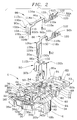
With reference now to Figure 2, the housing 4 is shown. The housing 4 has a front portion 28 which includes a device receiving region 30 wherein an electrical device 32, such as a capacitor or a resistor or a suppression device possibly in the form of a high frequency shielding choke, is provided to prevent spurious electro-magnetic radiation being transmitted to the device herein. The electrical component 32 includes a pair of conductive members 34a,34b which in this case are electrical leads extending therefrom. The component receiving region 30 of the front portion 28 includes a plurality of upstanding component positioning and retention members 36a-g that assure that the component 32 is properly positioned and positively retained within the housing 4. The leads 34a,34b extend into a first support structure 38 and a third support structure 40 respectively.
-
The first support structure 38 and the third support structure 40 are similarly configured and will be distinguished herein by the letter suffix "a" and "b" respectively while being described generally. Each of the support structures 38,40 include a forward supporting section 42a,b and a rearward supporting structure 44a,b. A longitudinally extending positioning slot 46a,b extends through the forward supporting sections 42a,b and the rearward supporting sections 44a,b for receiving the leads 34a,b of the electrical component 32 therein. The forward support structure 42a,b is separated from the rearward support structure 44a,b by a separating slot 48a,b extending transversely across the receiving channel 46a,b. The receiving channels 46a,b and separating slot 48a,b are open upwardly and include chamfered surfaces thereabout for aiding in the automatic assembly of the components, as will be described below.
-
Rearward of the first support structure 38 is first strap supporting structure that includes a side leg 50 oppositely disposed from a central post 52 and having bottom supports 54 therebetween to define a first strap channel 56. Rearward of the strap channel 56 and extending transversely thereto is a first retention channel 57 that is formed by opposing slots in the side leg 50 and the central post 52. On the opposite side of the central post 52, and spaced therefrom, is a second side leg 58 similar in construction and function to previously described side leg 50. Located between the central post 52 and the second side leg 58 is a second bottom support 60, whereby a second strap channel 62 is thereby defined. Rearward of the first strap channel 56 and extending transversely thereto is a second retention channel 63 that is formed by opposing slots in the side leg 58 and the central post 52. The first and second retention channels will be further described below.
-
Forward of the second strap channel 62 defining structure 52,58,60 is a first terminal receiving port 64 extending through the base 68 of the front portion 28 into communication with the circular opening 26. Rearward of the third support structure 40 and adjacent to the first terminal receiving port 64 is a second terminal receiving port 66 in communication with circular opening 24. The first and second ports 64,66 enable electrical interconnections to be formed from within the front portion 28 of the housing 4 to the terminals of the mating device (not shown).
-
Rearward of the first and second strap channels 56,62 is bulkhead 68. Extending across the bulkhead 68 into the front portion 28 are guideways 70a,70b. About the exterior periphery of the bulkhead 68 is a channel 72 defined by a flange 74 spaced from a rear surface 76 of the housing 4. The channel 72 may be partitioned by longitudinally extending ribs between the rear surface 76 and the flange 74, as will be described below with reference to the cover 8. Further extending rearward from bulkhead 68 is a frame 78. The frame 78 is defined by parallel and spaced apart side rails 80a,b interconnected on one side by the bulkhead 68 and oppositely therefrom by tie bar 82 to define an opening 84 therebetween. Extending upward from the tie bar 82 is a cylindrical boss 83 for use in positioning the cover 8 during assembly, as will be described below. A boss receiving structure 85 is located adjacent the first support structure 38 in the front portion 28 of the housing 4, also for positioning the cover 8.
-
Shown above the afore going described structure in Figure 2 are a first interconnection member 86, a second interconnection member 88 and a third interconnection member 90. The first interconnection member 86 is constructed for engaging the electrical lead 34a extending from the electrical component 32 that is located within the receiving channel 46a and one of the electrical conductors 18 of the cable 16. The second interconnection member 88 is constructed for engaging a terminal of the mating device and another one of the conductors 18 of the cable 16. The third interconnection member 90 is constructed for engaging another one of the leads 34b extending from the electrical component 32 and another one of the terminals of the mating device. This combination of electrical interconnection members 86,88,90, when engaged with the electrical component 32 and the conductors 18 of the cable 16, provides for an electrical interconnection circuit between the cable 16 and the mating device (not shown) with a suppression device 32 within the circuit that prevents spurious signals from being transmitted into the device.
-
The first electrical interconnection member 86, as is also the case with the second interconnection member 88 and the third interconnection member 90, is stamped and formed using conventional techniques from conductive material herein. The first interconnection member 86 includes an electrical component engaging end 92a and a conductor engaging end 94a interconnected by strap 96a. The electrical component engaging end 92a includes a downwardly bent tab 100a separated into opposing fingers 102a,b by a conductor engaging slot 104. Conductor engaging slot 104 is open downwardly at mouth 106. Mouth 106 is tapered inwardly and in communication with the engaging slot 104. As the connection device 34a,b of the component 32 may have insulation thereupon, such as common insulation upon an electrical wire or a varnish type insulation as is commonly disposed upon magnet wire conductors used in motor windings and similar applications, opposing cutting surfaces 108a,b are located below the slot 104 to part the insulation, thereby exposing the conductor therein to form a complete interconnection therewith. In this embodiment, the connection portion 92a is formed in a manner similar to Applicant's Mag-Mate interconnection system. Continuing from the engaging slot 104 is a cut 110 that provides additional resiliency to the fingers 102a,b. Rearward from the downwardly bent tab 100a is a hole 112a that is used for automated assembly of the device 2, whereby a pilot of the inserting tool fits therein for reliable locating. Extending rearward of the hole 112a is strap section 96a. A forward strap portion 114a extends from the electrical component engaging end 92a continuously to a rearward strap portion 116a which is offset therefrom by a downwardly disposed intermediate step 118a. Along the step 118a are opposing barbs 119a that bite into the respective sides of the retention channel 57 when the interconnection member 86 is inserted into the housing 4. The rearward portion 116a is interconnected with an upwardly open electrical conductor engaging end 94a.
-
The electrical conductor engaging end 94a, herein shown in the drawings, is advantageously adapted for interconnection with a flat flexible cable "FFC" 16. The construction used includes a plurality of triangular shaped upwardly pointing ears 120 where the peripheral surface 122 forms a cutting edge such that the intersection of the sides at 124 is especially sharp for piercing the insulation surrounding the conductors 18 of the FFC 16. The end is then crimped for engagement about the conductor 18 to form the electrical engagement. In the embodiment shown, conductor engaging portion 94a is advantageously open in the upward direction and includes an embossment 123 for better connection.
-
The second interconnection member 88 includes a terminal engaging end 126a interconnected with a conductor engaging end 94b by a centre strap section 96b. The conductor engaging end 94b and the central strap section 96b are similarly configured to the afore described structure relating to the first interconnection member 86, hence the similar reference numbers, and will not be again described herein. The forwardly disposed terminal engaging end 126a comprises a downwardly open opposing pair of cantilevered arms 128a,b. These arms are of conventional construction and extend forwardly from a base 130 in a generally parallel manner to a forward section where they converge towards each other at contact surfaces 130a,b before diverging to define a terminal receiving region 132, wherein a terminal of the device can be received and electrically engaged. The terminal engaging portion 126a is configured to fit within port 64 such that the terminal may be interconnected therewith.
-
The third electrical interconnection member 90 comprises a forwardly disposed electrical component engaging end 92b of similar construction of that described above with respect to the component engaging end 92a of the first interconnection member 86 herein. A hole 112b is included for the same purpose described above. A strap portion 96c interconnects the electrical component engaging end 92b with an electrical terminal engaging end 126b similarly constructed and configured as the electrical terminal engaging end 126a of the second interconnection member 88. The third interconnection member 90 has a strap portion 96c that spans the electrical component engaging end 92b and the terminal engaging end 126b, forming a U-shaped member. The electrical terminal engaging end 126b is configured to fit within port 66 for engaging the terminal received through the circular opening 24.
-
Each of the electrical interconnection members 86,88,90 are inserted into the housing 4 by being displaced in a downward direction of arrows A1,A2,A3 respectively. With respect first to the insertion of the first interconnection member 86, the lead 34a of the electrical component 32 extends into receiving channel 46a such that it spans the separating slot 48a and is supported on either side thereof. The interconnection member 86 is then brought down so that the tab 100a is aligned with the separating slot 48a and pressed therein. As the interconnection member 86 is being pressed therein the lead 46a is received within slot 104 displacing any insulation by way of cutting surfaces 108a,b to form electrical engagement therewith. In conjunction with the engagement of the device 32, intermediate step 118a is being received within the first retention channel 57 such that the barbs 119a interfere with the first side wall 50 and the central post 52 such that the interconnection member 86 is prevented from being dislodged during assembly or subsequent use. Forward strap portion 114a is disposed within first strap channel 56 and extends rearwardly therefrom such that the rearward portion 116a of the strap 96a is disposed within guideway 70a placing the electrical conductor engaging end 94a within opening 84 of the frame 78.
-
The second interconnection member 88 is inserted in the direction of arrow A2 so that the terminal engaging end 126a is aligned and received within port 64. The intermediate step 118b is received within the second retention channel 63 for retaining the interconnection member 88 in the manner described above. The forward strap portion 114b is retained, located and supported within the second strap channel 62 so that the rearward portion 116b of the strap section 96b is received within guideway 70b. The conductor engaging end 94b of the interconnection member 88 is similarly disposed within the opening 84 of the frame 78 as the conductor engaging end 94a of the first interconnection member 86.
-
The third interconnection member 90 is inserted into the housing 4 by being displaced in the direction of arrow A3. The tab 100b of the component engaging end 92b is received within separating slot 48b which is similarly spanned by the conductive lead 34b received within channel 46b, as described with reference to first interconnection member 86. The terminal engaging end 126b is also aligned and received within port 66 for engaging an electrical terminal of the mating device which extends through circular opening 24. Strap section 96c overlies a support member 134.
-
As may be observed in Figure 2, the housing 4 where the components are received has adequate chamfers thereabout to provide lead-in surfaces for the acceptance of the components. These chamfers advantageously assist in the reception of the mating components therein. As the component engaging ends 92a,b of the first interconnection member 86 and the third interconnection member 90 are open in the direction of insertion A1,A3, solderless electrical interconnection with the connective leads 34a,b of the electrical component 32 is formed as the interconnection members 86,90 are inserted into the housing 4.
-
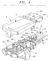
In accordance with the above described assembly, the partially assembled electrical connector 2 is shown in Figure 3. Cover 8 includes a forward retention arm 136 having a barb 138 thereupon for engaging a ledge 140 of the housing 4. Rearward along the side of the cover are oppositely disposed latching straps 142 that extend downwardly therefrom. Each latching strap 142 is singularly configured and contains an opening 144 therein for receipt of a latch 146 located in a relieved portion 148 of the connector housing 4 that is proportioned to receive the strap 142 therein. The latch 146 includes a camming surface 150 for spreading the straps 142 so that the straps 142 may pass outward over the latch 146, thereby enabling the latch 146 to be received within opening 144.
-
Rearward of the straps 142 is an upper bulkhead 150 that corresponds to the lower bulkhead 68. The upper bulkhead 150 includes a flange 152 spaced rearward from a rear surface 154 of the cover 8 defining a channel 156 therebetween. The channel 156 is partitioned by a plurality of ribs 158 into cavities for the purposes described below. Extending rearward from the bulkhead 150 is a closed frame 160 similar to that described below with respect to frame 78 but having the addition of a plate 162 thereover. Extending downward from the closed frame 160 are oppositely disposed rear retention arms 164 having barbs 166 for receipt within openings along arms 78 of the housing 4. At the rearward end of the closed frame 160 is a boss receiving opening 167 for receiving the boss 83 during the assembly process to assure proper alignment is maintained in light of the reactionary forces involved in latching the cover 8 to the housing 4. A boss (not shown) is also included as part of the cover 8 that corresponds to the boss receiving structure 85 in the front portion 28 of the housing 4.
-
In the partially assembled configuration shown in Figure 3, a support member (not shown) used for assembly purposes may extend up through the opening 84 of the frame 78 to support the conductor engaging ends 94a,94b as the conductor 16 is displaced downwardly in the direction of arrow B, thereby forming an electrical interconnection with the conductor engaging ends 94a,94b. Note, that as shown in Figure 4, an advantageous construction would have a hole 169 formed in the cable 16 that receives the boss 83 for cable positioning. The support member may then be removed from the opening 84 resulting in the partially assembled structure shown in Figure 4.
-
With reference now to Figure 4, by displacing the cover downward along arrow C, the cover 8 and the housing 4 may be snap-fit together, thereby providing an electrical connector 2 where all of the assembly steps involve motion A,B,C along a common axis, thereby making this especially suitable for automated assembly techniques. Once the cover 8 has been snapped upon the housing 4, the connector may be placed within a moulding apparatus where a rear boot 12 will be overmoulded about the bulkheads 68,150 and extend rearward out over the frames 78,160 to a unitarily formed strain relief tail 14.
-
The overmoulded boot 12 is formed by flowing the melt about the rear frame portions 78, 160 so that the melt is received within the channel 72, 156 of the bulkheads 68,150 respectively for positively locking the boot 12 to the housing 4 and the cover 8. If partitioning ribs 158 are included the melt will flow into the cavities therebetween and set therein. In addition, by positively locking the boot 12 to the cover 8 and housing 4 in this manner the housing 4 and cover 8 are prevented from becoming disengaged. Furthermore, the melt may be injected over the plate 162 to provide protection of the crimped interconnection with the cable 16 that is formed thereunder, thereby preventing the adverse effects of the moulding pressure upon the crimped connection. Advantageously, the melt may be allowed to flow around the side rails 80a,b and fill the opening 84 from below to form a solid mass thereabout to further protect the crimps.
-
Extending unitarily outward from the boot 12, along the conductive cable 16, is the strain relief tail 14. The strain relief tail 14 includes a tie-bar 170 extending along and around one edge of the conductive cable 16. Extending across the cable 16 from the tie-bar 170 and around the other edge are a plurality of spaced apart straps 172. Along the tie-bar 170, and corresponding to each of the straps 72, are circular openings 174. Physical engagement of the cable may be enhanced by providing openings or surface regularities along the insulation wherein the melt that forms the strain relief tail 14 may flow for engagement therewith. Other strain relief tail configurations may also be advantageously used.
-
Advantageously then, an electrical connector is provided that is especially advantageous for use with automated assembly, as all assembly motion is directed along a common axis. In addition, the interconnections are formed without the use of solder and the associated heat and chemical by-products. Furthermore, by overmoulding a strain relief boot about the cover and the housing, the components contained therein are prevented from becoming dislodged as the cover is positively retained. Finally, by unitarily moulding a strain relief tail with the strain relief boot external forces exerted upon the insulated cable are transferred directly into the housing and the cover as opposed to disrupting the interconnection with the conductors of the cable.