EP0698475B1 - Resin moulding method and apparatus - Google Patents
Resin moulding method and apparatus Download PDFInfo
- Publication number
- EP0698475B1 EP0698475B1 EP95303195A EP95303195A EP0698475B1 EP 0698475 B1 EP0698475 B1 EP 0698475B1 EP 95303195 A EP95303195 A EP 95303195A EP 95303195 A EP95303195 A EP 95303195A EP 0698475 B1 EP0698475 B1 EP 0698475B1
- Authority
- EP
- European Patent Office
- Prior art keywords
- resin
- catalyst
- mould
- reservoirs
- main conduit
- Prior art date
- Legal status (The legal status is an assumption and is not a legal conclusion. Google has not performed a legal analysis and makes no representation as to the accuracy of the status listed.)
- Expired - Lifetime
Links
Images


Classifications
-
- B—PERFORMING OPERATIONS; TRANSPORTING
- B29—WORKING OF PLASTICS; WORKING OF SUBSTANCES IN A PLASTIC STATE IN GENERAL
- B29C—SHAPING OR JOINING OF PLASTICS; SHAPING OF MATERIAL IN A PLASTIC STATE, NOT OTHERWISE PROVIDED FOR; AFTER-TREATMENT OF THE SHAPED PRODUCTS, e.g. REPAIRING
- B29C45/00—Injection moulding, i.e. forcing the required volume of moulding material through a nozzle into a closed mould; Apparatus therefor
- B29C45/17—Component parts, details or accessories; Auxiliary operations
- B29C45/46—Means for plasticising or homogenising the moulding material or forcing it into the mould
-
- B—PERFORMING OPERATIONS; TRANSPORTING
- B29—WORKING OF PLASTICS; WORKING OF SUBSTANCES IN A PLASTIC STATE IN GENERAL
- B29C—SHAPING OR JOINING OF PLASTICS; SHAPING OF MATERIAL IN A PLASTIC STATE, NOT OTHERWISE PROVIDED FOR; AFTER-TREATMENT OF THE SHAPED PRODUCTS, e.g. REPAIRING
- B29C45/00—Injection moulding, i.e. forcing the required volume of moulding material through a nozzle into a closed mould; Apparatus therefor
- B29C45/16—Making multilayered or multicoloured articles
-
- B—PERFORMING OPERATIONS; TRANSPORTING
- B29—WORKING OF PLASTICS; WORKING OF SUBSTANCES IN A PLASTIC STATE IN GENERAL
- B29C—SHAPING OR JOINING OF PLASTICS; SHAPING OF MATERIAL IN A PLASTIC STATE, NOT OTHERWISE PROVIDED FOR; AFTER-TREATMENT OF THE SHAPED PRODUCTS, e.g. REPAIRING
- B29C67/00—Shaping techniques not covered by groups B29C39/00 - B29C65/00, B29C70/00 or B29C73/00
- B29C67/24—Shaping techniques not covered by groups B29C39/00 - B29C65/00, B29C70/00 or B29C73/00 characterised by the choice of material
- B29C67/246—Moulding high reactive monomers or prepolymers, e.g. by reaction injection moulding [RIM], liquid injection moulding [LIM]
-
- B—PERFORMING OPERATIONS; TRANSPORTING
- B29—WORKING OF PLASTICS; WORKING OF SUBSTANCES IN A PLASTIC STATE IN GENERAL
- B29C—SHAPING OR JOINING OF PLASTICS; SHAPING OF MATERIAL IN A PLASTIC STATE, NOT OTHERWISE PROVIDED FOR; AFTER-TREATMENT OF THE SHAPED PRODUCTS, e.g. REPAIRING
- B29C70/00—Shaping composites, i.e. plastics material comprising reinforcements, fillers or preformed parts, e.g. inserts
- B29C70/04—Shaping composites, i.e. plastics material comprising reinforcements, fillers or preformed parts, e.g. inserts comprising reinforcements only, e.g. self-reinforcing plastics
- B29C70/28—Shaping operations therefor
- B29C70/40—Shaping or impregnating by compression not applied
- B29C70/42—Shaping or impregnating by compression not applied for producing articles of definite length, i.e. discrete articles
- B29C70/46—Shaping or impregnating by compression not applied for producing articles of definite length, i.e. discrete articles using matched moulds, e.g. for deforming sheet moulding compounds [SMC] or prepregs
- B29C70/48—Shaping or impregnating by compression not applied for producing articles of definite length, i.e. discrete articles using matched moulds, e.g. for deforming sheet moulding compounds [SMC] or prepregs and impregnating the reinforcements in the closed mould, e.g. resin transfer moulding [RTM], e.g. by vacuum
-
- B—PERFORMING OPERATIONS; TRANSPORTING
- B29—WORKING OF PLASTICS; WORKING OF SUBSTANCES IN A PLASTIC STATE IN GENERAL
- B29C—SHAPING OR JOINING OF PLASTICS; SHAPING OF MATERIAL IN A PLASTIC STATE, NOT OTHERWISE PROVIDED FOR; AFTER-TREATMENT OF THE SHAPED PRODUCTS, e.g. REPAIRING
- B29C70/00—Shaping composites, i.e. plastics material comprising reinforcements, fillers or preformed parts, e.g. inserts
- B29C70/04—Shaping composites, i.e. plastics material comprising reinforcements, fillers or preformed parts, e.g. inserts comprising reinforcements only, e.g. self-reinforcing plastics
- B29C70/28—Shaping operations therefor
- B29C70/54—Component parts, details or accessories; Auxiliary operations, e.g. feeding or storage of prepregs or SMC after impregnation or during ageing
-
- B—PERFORMING OPERATIONS; TRANSPORTING
- B29—WORKING OF PLASTICS; WORKING OF SUBSTANCES IN A PLASTIC STATE IN GENERAL
- B29C—SHAPING OR JOINING OF PLASTICS; SHAPING OF MATERIAL IN A PLASTIC STATE, NOT OTHERWISE PROVIDED FOR; AFTER-TREATMENT OF THE SHAPED PRODUCTS, e.g. REPAIRING
- B29C45/00—Injection moulding, i.e. forcing the required volume of moulding material through a nozzle into a closed mould; Apparatus therefor
- B29C45/17—Component parts, details or accessories; Auxiliary operations
- B29C45/46—Means for plasticising or homogenising the moulding material or forcing it into the mould
- B29C2045/468—Means for plasticising or homogenising the moulding material or forcing it into the mould using a fluid as directly acting injection means
Definitions
- That one of the reservoirs 32, 34 which is connected to the injection line 28 is pressurised by supply pressure 36 which exerts pressure on the resin in the reservoir to force the resin out of the reservoir, along the injection line 28, through the valve 30 and into the mould cavity 26.
- the mould cavity 26 is vented at 27.
Landscapes
- Engineering & Computer Science (AREA)
- Mechanical Engineering (AREA)
- Manufacturing & Machinery (AREA)
- Chemical & Material Sciences (AREA)
- Composite Materials (AREA)
- Casting Or Compression Moulding Of Plastics Or The Like (AREA)
- Injection Moulding Of Plastics Or The Like (AREA)
Description
- This invention relates to the moulding of products from thermosetting resins, and in particular to resin transfer moulding. In this process, a fibrous reinforcement preform is placed in a mould, the mould is closed and resin is introduced into the mould cavity to wet the preform and to fill the mould. When the resin has set, a finished component can be taken from the mould and passed to any necessary clean up processes.
- The choice of the resin system (resin plus catalyst) is carefully chosen to ensure that the resin does flow completely to the edges of the mould cavity before it sets, but so that setting takes place as soon as possible after the mould is completely filled.
- In order for resin transfer moulding to be useful for the production of components in volume, it is necessary to reduce the cycle time, ie the time between successive openings of the mould, as far as possible.
- It is known from US-PS 4 404 261 to assist uniform cure of a product moulded from a plurality of solid plies of polymeric material by using different catalysts in different plies, such that less heat is required to initiate the curing of the plies at the centre of the product than is required at the edges. This is intended to promote uniform curing throughout the product, when heat is applied to the product only at the edges.
- It is also known from EP-A-0 529 651 to maintain resin and catalyst in separate reservoirs, and to mix the two in a mixing head, from where the now-catalysed resin is fed to a mould. More than one resin/catalyst mixture can be mixed in the same mixing head.
- According to the present invention, there is provided a resin transfer moulding method for moulding products from thermosetting resins, whereby a continuous flow of resin into a mould cavity begins with a resin mixed with a first catalyst and changes before the mould is full to the same resin mixed with a second catalyst, with the first catalyst being chosen to set the resin at a higher temperature than the second catalyst.
- In a method using resin systems which set at different temperatures, and in which cold resin is introduced into a heated mould, the first resin introduced will be heated by the stored heat of the mould, and the incoming cold resin will tend to reduce the temperature of the mould at the injection point. By using a cold setting resin to form the part of the component around the injection point, the setting of the resin and therefore the process cycle can be considerably speeded up compared to the case where a hot setting resin is introduced to the mould at the end of the process, in the area of the, now cold, resin injection point.
- The change in resin system could be continuous throughout the injection phase, to produce a profiling effect, rather than discrete resin systems.
- The invention also provides apparatus for moulding products from thermosetting resins, the apparatus comprising a reservoir for uncatalysed resin, a main conduit extending from the reservoir for connection to a mould, means for forcing resin to flow through the main conduit into the mould, at least two independent catalyst reservoirs, characterised in a stirrer for mixing the catalysts and the resin, in that the at least two catalyst reservoirs are for containing different catalysts and are associated with a single uncatalysed resin reservoir and in that means are provided for connecting one or the other of the catalyst reservoirs to the main conduit.
- A valve will be provided to switch over from one catalyst reservoir to the other, and it is important that there should be no introduction of air or other foreign matter when changeover takes place.
- Initiation of changeover can be in response to the elapsing of a period of time after the commencement of resin introduction, or on the sensing of a particular parameter associated with resin introduction, for example the changeover may be initiated when a sensor in the mould detects that the resin front has reached a pre-determined position within the mould.
- If a continuously changing resin system is being used, more sophisticated equipment would be required, for example to provide a continuously changing catalyst composition to be fed into a resin stream.
- The invention will now be further described, by way of example, with reference to the accompanying drawings, in which:
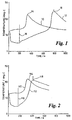
- Figure 1 is a graph showing the thermal history of a resin transfer moulding cycle, in accordance with the prior art;
- Figure 2 is a graph corresponding to the graph of Figure 1 but showing the thermal history of a resin transfer moulding cycle in accordance with the invention;
- Figure 3 is a schematic illustration of an equipment used to achieve a resin transfer moulding cycle; and
- Figure 4 is a schematic illustration of the apparatus in accordance with the invention.
-
- Figures 1 and 2 are graphs on which temperature is plotted against time. In Figure 1, the
curve 10 represents the thermal history at the periphery of a resin transfer mould, and thecurve 12 represents the thermal history at the resin injection gate of the same mould. In Figure 2, the same features are designated with the same reference numerals, prefixed by "1". - In resin transfer moulding, the resin is mixed with catalyst before or as it enters the mould cavity. The setting or curing process has therefore already begun (but with a negligible degree of conversion) as the resin begins to flow through the mould, but it is essential that the resin reaches the extremities of the mould cavity before it sets. Normally, the resin will be introduced cold into a heated mould, and the activity of the catalyst and the temperature of the mould will be determined so that the resin is able to flow to the edges of the mould but begins to set as soon as it reaches the mould edges. The actual setting process for the resin is exothermic, so the occurrence of setting can be monitored by watching the temperature using probes in the mould wall. The probes may be mounted flush to the internal surface of the mould cavity or may protrude into the surface of the moulded part.
- Looking now at the example illustrated in Figure 1, the mould is initially heated to a temperature of about 60°C. As the cold resin is introduced at the injection gate of the mould, there is little initial change in the temperature at the mould periphery as shown by
curve 10. However, the temperature rises sharply to apeak 14 when the resin begins to cure at the mould periphery. The resin is substantially cured and set at the mould periphery after about 350 seconds, and the temperature at the mould periphery thereafter gradually drops back to the original mould temperature. - However, at the injection gate, as shown by the
curve 12, the temperature initially drops sharply when the cold resin is introduced. Once injection is completed, after about 200 seconds and as indicated by theline 16, the temperature of the resin at the injection gate begins to rise until it reaches a temperature of about 70°C at which curing can start. Thereafter the temperature at the injection gate rises to apeak 18 and it is only when this peak is reached that the resin is completely set throughout the mould. In the illustration shown, this results in a cure time for the last parts to cure of about 800 seconds from the start of injection. - Turning now to Figure 2, it will be seen that the
curve 110 representing the thermal history at the mould periphery is effectively unchanged from thecurve 10 in Figure 1, and also the temperature profiles during injection are substantially the same. - The difference however between the two situations is that in Figure 2, the resin introduced last, ie the resin which remains in the vicinity of the injection gate, is a resin which starts to cure at a relatively low temperature. It is therefore not necessary to wait until the stored heat in the mould heats up the resin before cure can begin; instead, cure begins in this case at a low temperature of about 30°C resulting in the completion of cure at the injection gate after about 400 seconds.
- In this example, by using a cold curing catalyst at the end of the mould cycle and a hot curing catalyst at the beginning of the mould cycle, a cycle time reduction of about 50% has been possible.
- Figure 3 shows the equipment used to achieve this cycle time reduction.
- A
mould 20 has anupper half 22, alower half 24, and acavity 26. Resin is injected into the mould (in which a preform - not shown - has previously been located) through aninjection conduit 28. Aresin inlet valve 30 is provided in theconduit 28. - Two
parallel reservoir reservoir 34 is located a hot curing resin system and in thereservoir 32 is located a cold curing resin system. Achangeover valve 36 is operable to connect either thereservoir 34 or thereservoir 32 to theinjection line 28. - That one of the
reservoirs injection line 28 is pressurised bysupply pressure 36 which exerts pressure on the resin in the reservoir to force the resin out of the reservoir, along theinjection line 28, through thevalve 30 and into themould cavity 26. - The
mould cavity 26 is vented at 27. - In use, the
changeover valve 36 is initially set to connect the hotcuring system reservoir 34 to theinjection line 28. Theinlet valve 30 is then opened and the hot curing resin is injected into the mould cavity. The resin begins to flow out of the mould cavity, from the centre towards the edges. Although a centre pin gate is described here, the method of the invention can be used with a variety of different gate arrangements. - At a pre-determined stage during the injection process, the
changeover valve 36 is operated to disconnect the hotcuring system reservoir 34 from theinjection line 28 and to connect the coldcuring system reservoir 32 to the injection line, so that the cold curing resin is forced into theinjection line 28, following immediately behind the hot curing resin system. Thechangeover valve 36 will be constructed to ensure that no air or other extraneous matter is admitted when changeover takes place, and feed from the cold curing system will continue until the mould is completely full. - Because the cold curing resin will begin to cure as soon as it enters the mould (which will at this point be at a temperature of about 30°C), the resin close to the injection gate will set only a short time after the resin at the mould periphery.
- In the apparatus shown in Figure 4, there is only one resin reservoir and two separate catalyst reservoirs are provided, for admixture to the resin.
- The
mould 20 in Figure 4 is the same as themould 20 in Figure 3. However, a different set of components is arranged externally of the mould. The mould also incorporates aresin arrival sensor 50. - In this apparatus there is a
single resin reservoir 52, a hotcuring catalyst reservoir 54 and a coldcuring catalyst reservoir 56. Achangeover valve 58 connects either one or the other of these two reservoirs via aline 60 to apump 62 which then leads into theinjection line 28 at 64. - A
second pump 66 is used to pump resin from thereservoir 52 into theline 28, and the resin and the admixed catalyst then pass together through astatic mixer 68 which ensures adequate mixing of the resin and catalyst before the resin system enters themould cavity 26. - In this apparatus, operation is controlled by a
computer 70 which receives inputs from theresin arrival sensor 50 and apump counter 72 which monitors theresin pump 66. Thecomputer 70 also controls operation of thechangeover valve 58 and theinlet valve 30. - In use, with the
pumps changeover valve 58 set to allow flow of the high temperature catalyst fromreservoir 54 into theline 60, a resin mixture with a hot curing catalyst is injected into themould cavity 26. - When the resin arrival sensor detects the arrival of a resin front, indicating that the
mould cavity 26 is partially filled, a signal is sent to thecomputer 70 which sends a signal to thechangeover valve 58 to initiate a change from thereservoir 54 to thereservoir 56. Thereafter thepump 62 will be pumping the cold curing catalyst and a mixture of resin and cold curing catalyst will complete the filling of the mould. - Working in this way results in a thermal history of the type shown in Figure 2, where the completion of cure of the cold curing system at the injection gate is completed at
point 118, only a relatively short time after completion of the cure at the mould periphery at 114. - The apparatus of Figure 4 is suited to a continuous production process because the resin and catalysts are only mixed together immediately before being introduced into the mould cavity. In the equipment of Figure 3 when the resin and catalyst are pre-mixed, pre-mixing is likely to take place in batches and each batch must be injected into a mould within a pre-determined time after mixing of the batch, because the resin will only have a limited time before it will set.
Claims (7)
- A resin transfer moulding method for moulding products from thermosetting resins, whereby a continuous flow of resin into a mould cavity (26) begins with a resin mixed with a first catalyst and changes before the mould is full to the same resin mixed with a second catalyst, with the first catalyst being chosen to set the resin at a higher temperature than the second catalyst.
- A method as claimed in any preceding claim, characterised in that there are more than two resin/catalyst mixture, with successive mixtures setting at a lower temperature than the preceding mixture.
- A method as claimed in Claim 2, characterised in that the change in resin/catalyst mixtures is continuous throughout the stage whilst resin flows into the mould.
- Apparatus for moulding products from thermosetting resins, the apparatus comprising a reservoir (52) for uncatalysed resin, a main conduit (28) extending from the reservoir for connection to a mould (20), means (66) for forcing resin to flow through the main conduit into the mould (20), at least two independent catalyst reservoirs (54,56), characterised in a stirrer (68) for mixing the catalysts and the resin, in that the at least two catalyst reservoirs are for containing different catalysts and are associated with a single uncatalysed resin reservoir and in that means (58) are provided for connecting one or the other of the catalyst reservoirs to the main conduit.
- Apparatus as claimed in Claim 4, characterised in that the means (58) for connecting one of the catalyst reservoirs (54,56) to the main conduit whilst disconnecting the other of the catalyst reservoirs (56,54) from the main conduit(28), and vice versa, includes means (70) to initiate changeover between the two catalyst reservoirs (54,56) in response to the elapsing of a period of time after the commencement of resin introduction to a mould (20).
- Apparatus as claimed in Claim 4, characterised in that the means (58) for connecting one of the catalyst reservoirs (54,56) to the main conduit whilst disconnecting the other of the catalyst reservoirs (56,54) from the main conduit (28), and vice versa, includes means (70) to initiate changeover between the two catalyst reservoirs in response to the sensing of a particular parameter associated with resin introduction.
- Apparatus as claimed in Claim 6, characterised in that the changeover is initiated when a sensor (50) in the mould detects that the resin front has reached a pre-determined position within the mould.
Priority Applications (1)
| Application Number | Priority Date | Filing Date | Title |
|---|---|---|---|
| US08/505,986 US5906782A (en) | 1994-07-23 | 1995-07-24 | Method for the simultaneous curing of thermosetting resins |
Applications Claiming Priority (2)
| Application Number | Priority Date | Filing Date | Title |
|---|---|---|---|
| GB9415277A GB2291618A (en) | 1994-07-23 | 1994-07-23 | Moulding method and apparatus |
| GB9415277 | 1994-07-23 |
Publications (3)
| Publication Number | Publication Date |
|---|---|
| EP0698475A2 EP0698475A2 (en) | 1996-02-28 |
| EP0698475A3 EP0698475A3 (en) | 1996-09-04 |
| EP0698475B1 true EP0698475B1 (en) | 2000-07-12 |
Family
ID=10759043
Family Applications (1)
| Application Number | Title | Priority Date | Filing Date |
|---|---|---|---|
| EP95303195A Expired - Lifetime EP0698475B1 (en) | 1994-07-23 | 1995-05-12 | Resin moulding method and apparatus |
Country Status (3)
| Country | Link |
|---|---|
| EP (1) | EP0698475B1 (en) |
| DE (1) | DE69517885T2 (en) |
| GB (1) | GB2291618A (en) |
Families Citing this family (5)
| Publication number | Priority date | Publication date | Assignee | Title |
|---|---|---|---|---|
| GB2301059B (en) * | 1995-05-24 | 2000-01-12 | Ford Motor Co | Resin transfer moulding |
| US20060111497A1 (en) * | 2004-11-23 | 2006-05-25 | Hochgesang Paul J | Liquid rubber article in situ compounding into a forming mold |
| DE102009058431B4 (en) * | 2009-12-16 | 2017-08-31 | Airbus Defence and Space GmbH | Marking and analysis of matrix properties in fiber-reinforced plastic components |
| CN103847112A (en) * | 2014-02-14 | 2014-06-11 | 江苏恒神纤维材料有限公司 | RTM (resin transfer moulding) mould with resin intercepting outlet |
| CN115771286B (en) * | 2022-11-17 | 2025-08-26 | 中国航空制造技术研究院 | Reciprocating resin injection device |
Family Cites Families (17)
| Publication number | Priority date | Publication date | Assignee | Title |
|---|---|---|---|---|
| GB1369744A (en) * | 1973-05-03 | 1974-10-09 | Ici Ltd | Injection moulding |
| GB1513375A (en) * | 1974-07-26 | 1978-06-07 | Leader Ltd D | Moulding process |
| DE2817687A1 (en) * | 1978-04-22 | 1979-10-31 | Elastogran Gmbh | Mixer for polyurethane components - has chamber with stirrer which is removed when split housing is opened |
| US4315724A (en) * | 1979-12-19 | 1982-02-16 | Kamaya Kagaku Kogyo Co., Ltd. | Process and machine for multi-color injection molding |
| US4404261A (en) * | 1981-10-13 | 1983-09-13 | Owens-Corning Fiberglas Corporation | Method of molding multi-ply polymeric composites including simultaneous curing of plural layers having different catalyst polymerization initiation temperatures and product thereof |
| DE3238090A1 (en) * | 1982-10-14 | 1984-04-19 | Battenfeld Maschinenfabriken Gmbh, 5882 Meinerzhagen | PLASTIC MOLDED BODY |
| CH661472A5 (en) * | 1983-04-22 | 1987-07-31 | Theodor Schoettli | METHOD AND DEVICE FOR AT LEAST TWO-STAGE INJECTION MOLDING OF COMPOSED MOLDED BODIES MADE OF POLYMERS, AND USE OF THE METHOD. |
| DE3521948A1 (en) * | 1984-06-20 | 1986-01-09 | Elastogran Maschinenbau GmbH, 2844 Lemförde | Process and device for processing multi-component plastics, in particular polyurethane |
| US4701292A (en) * | 1984-09-13 | 1987-10-20 | Husky Injection Molding Systems Ltd. | Method for pressure molding objects of different resins |
| JPS61297116A (en) * | 1985-06-27 | 1986-12-27 | Canon Inc | Injection molding machine |
| JPS6369614A (en) * | 1986-09-10 | 1988-03-29 | Mazda Motor Corp | Multi-layer reactive injection molding |
| GB8623323D0 (en) * | 1986-09-29 | 1986-11-05 | Harper A R | Injecting liquid resin |
| DE3640474A1 (en) * | 1986-11-27 | 1988-06-09 | Phoenix Ag | Process for producing mouldings from polyurethane integral foam |
| IT1211375B (en) * | 1987-09-30 | 1989-10-18 | Fiat Auto Spa | BODYWORK OF THE VEHICLE PROCEDURE FOR THE PRODUCTION THROUGH INJECTION MOLDING OF STRUCTURAL ELEMENTS OF THERMOSETTING PLASTIC MATERIAL PARTICULARLY OF COMPONENT PARTS OF THE |
| US5034173A (en) * | 1990-04-26 | 1991-07-23 | General Motors Corporation | Method of manufacturing a plastic motor vehicle door |
| IT1251181B (en) * | 1991-08-28 | 1995-05-04 | Sviluppo Settori Impiego Srl | PROCEDURE FOR INJECTION PRINTING POLYMERIZABLE NON-PRE-CATALYZED HIGH-PRESSURE AND CAPACITY RESINS. |
| JP2746024B2 (en) * | 1992-10-30 | 1998-04-28 | 豊田合成株式会社 | RIM polyurethane two-color molding method |
-
1994
- 1994-07-23 GB GB9415277A patent/GB2291618A/en not_active Withdrawn
-
1995
- 1995-05-12 DE DE69517885T patent/DE69517885T2/en not_active Expired - Fee Related
- 1995-05-12 EP EP95303195A patent/EP0698475B1/en not_active Expired - Lifetime
Also Published As
| Publication number | Publication date |
|---|---|
| EP0698475A3 (en) | 1996-09-04 |
| GB9415277D0 (en) | 1994-09-21 |
| DE69517885D1 (en) | 2000-08-17 |
| GB2291618A (en) | 1996-01-31 |
| DE69517885T2 (en) | 2000-11-16 |
| EP0698475A2 (en) | 1996-02-28 |
Similar Documents
| Publication | Publication Date | Title |
|---|---|---|
| US5906782A (en) | Method for the simultaneous curing of thermosetting resins | |
| CN101484299A (en) | Device and method for processing thermosetting plastics | |
| CN100509361C (en) | Method and device for producing a structural component having a tight Polyurethane (PUR) sealing layer | |
| EP0698475A2 (en) | Resin moulding method and apparatus | |
| GB2301059A (en) | Resin transfer moulding with controlled heating of resin | |
| EP0648594A2 (en) | Device for moulding articles of composite material and process using such a device | |
| JPS6233926B2 (en) | ||
| CN100548614C (en) | Guidance of pressure and temperature in an in-mold coating process | |
| CN105793003A (en) | Equipment for polymerizing lactams in molds | |
| JP3513718B2 (en) | Structure reaction injection molding apparatus and structure reaction injection molding method | |
| CN110539507A (en) | Rapid pultrusion process | |
| JPH04286612A (en) | Manufacture of fiber reinforced plastic molding with flange | |
| KR100231252B1 (en) | Fiber reinforced plastic manufacturing method and apparatus | |
| JPH05212745A (en) | Method for injection molding of preliminary catalyst-free polymerizable single component resin under high pressure and in high flow amount | |
| JP3101011B2 (en) | Multi-component mixed resin molding method and apparatus | |
| Johnson et al. | Cycle time reductions in resin transfer moulding using microwave preheating | |
| JPS5593437A (en) | Injection molding process with thermo-linked reaction of rubber and synthetic resin | |
| EP1009611A1 (en) | Lattice gate for injection molding of rubber compounds | |
| JP3003699B1 (en) | Method and apparatus for producing sheet-like reinforcing material | |
| JPH082543B2 (en) | Molding method for fiber reinforced plastic moldings | |
| JPH0753951Y2 (en) | Reaction injection mold | |
| CN109705535A (en) | A kind of Shooting Technique of plastic tub | |
| EP3815886B1 (en) | A method for producing hybrid composite parts | |
| JPS60219035A (en) | Manufacture of fiber reinforced resin formed product with coating layer | |
| JPS6369606A (en) | Adding agent pouring device for molten resin |
Legal Events
| Date | Code | Title | Description |
|---|---|---|---|
| PUAI | Public reference made under article 153(3) epc to a published international application that has entered the european phase |
Free format text: ORIGINAL CODE: 0009012 |
|
| AK | Designated contracting states |
Kind code of ref document: A2 Designated state(s): DE FR GB IT |
|
| PUAL | Search report despatched |
Free format text: ORIGINAL CODE: 0009013 |
|
| AK | Designated contracting states |
Kind code of ref document: A3 Designated state(s): DE FR GB IT |
|
| 17P | Request for examination filed |
Effective date: 19961111 |
|
| 17Q | First examination report despatched |
Effective date: 19970512 |
|
| GRAG | Despatch of communication of intention to grant |
Free format text: ORIGINAL CODE: EPIDOS AGRA |
|
| GRAG | Despatch of communication of intention to grant |
Free format text: ORIGINAL CODE: EPIDOS AGRA |
|
| GRAG | Despatch of communication of intention to grant |
Free format text: ORIGINAL CODE: EPIDOS AGRA |
|
| GRAG | Despatch of communication of intention to grant |
Free format text: ORIGINAL CODE: EPIDOS AGRA |
|
| GRAH | Despatch of communication of intention to grant a patent |
Free format text: ORIGINAL CODE: EPIDOS IGRA |
|
| GRAH | Despatch of communication of intention to grant a patent |
Free format text: ORIGINAL CODE: EPIDOS IGRA |
|
| GRAA | (expected) grant |
Free format text: ORIGINAL CODE: 0009210 |
|
| AK | Designated contracting states |
Kind code of ref document: B1 Designated state(s): DE FR GB IT |
|
| REF | Corresponds to: |
Ref document number: 69517885 Country of ref document: DE Date of ref document: 20000817 |
|
| ITF | It: translation for a ep patent filed | ||
| ET | Fr: translation filed | ||
| PLBE | No opposition filed within time limit |
Free format text: ORIGINAL CODE: 0009261 |
|
| STAA | Information on the status of an ep patent application or granted ep patent |
Free format text: STATUS: NO OPPOSITION FILED WITHIN TIME LIMIT |
|
| 26N | No opposition filed | ||
| REG | Reference to a national code |
Ref country code: GB Ref legal event code: IF02 |
|
| PGFP | Annual fee paid to national office [announced via postgrant information from national office to epo] |
Ref country code: GB Payment date: 20030428 Year of fee payment: 9 |
|
| PGFP | Annual fee paid to national office [announced via postgrant information from national office to epo] |
Ref country code: FR Payment date: 20030512 Year of fee payment: 9 |
|
| PGFP | Annual fee paid to national office [announced via postgrant information from national office to epo] |
Ref country code: DE Payment date: 20030514 Year of fee payment: 9 |
|
| REG | Reference to a national code |
Ref country code: FR Ref legal event code: TP |
|
| PG25 | Lapsed in a contracting state [announced via postgrant information from national office to epo] |
Ref country code: GB Free format text: LAPSE BECAUSE OF NON-PAYMENT OF DUE FEES Effective date: 20040512 |
|
| PG25 | Lapsed in a contracting state [announced via postgrant information from national office to epo] |
Ref country code: DE Free format text: LAPSE BECAUSE OF NON-PAYMENT OF DUE FEES Effective date: 20041201 |
|
| GBPC | Gb: european patent ceased through non-payment of renewal fee |
Effective date: 20040512 |
|
| PG25 | Lapsed in a contracting state [announced via postgrant information from national office to epo] |
Ref country code: FR Free format text: LAPSE BECAUSE OF NON-PAYMENT OF DUE FEES Effective date: 20050131 |
|
| REG | Reference to a national code |
Ref country code: FR Ref legal event code: ST |
|
| PG25 | Lapsed in a contracting state [announced via postgrant information from national office to epo] |
Ref country code: IT Free format text: LAPSE BECAUSE OF NON-PAYMENT OF DUE FEES;WARNING: LAPSES OF ITALIAN PATENTS WITH EFFECTIVE DATE BEFORE 2007 MAY HAVE OCCURRED AT ANY TIME BEFORE 2007. THE CORRECT EFFECTIVE DATE MAY BE DIFFERENT FROM THE ONE RECORDED. Effective date: 20050512 |