EP0698168B1 - Overhead garage door bottom bracket - Google Patents
Overhead garage door bottom bracket Download PDFInfo
- Publication number
- EP0698168B1 EP0698168B1 EP94920659A EP94920659A EP0698168B1 EP 0698168 B1 EP0698168 B1 EP 0698168B1 EP 94920659 A EP94920659 A EP 94920659A EP 94920659 A EP94920659 A EP 94920659A EP 0698168 B1 EP0698168 B1 EP 0698168B1
- Authority
- EP
- European Patent Office
- Prior art keywords
- bracket
- door
- assembly
- planar surface
- spring
- Prior art date
- Legal status (The legal status is an assumption and is not a legal conclusion. Google has not performed a legal analysis and makes no representation as to the accuracy of the status listed.)
- Expired - Lifetime
Links
- 230000001419 dependent effect Effects 0.000 claims 1
- 230000013011 mating Effects 0.000 abstract 1
- 239000002184 metal Substances 0.000 description 5
- 238000004519 manufacturing process Methods 0.000 description 3
- 238000005520 cutting process Methods 0.000 description 2
- 230000006378 damage Effects 0.000 description 2
- 238000006073 displacement reaction Methods 0.000 description 1
- 230000000977 initiatory effect Effects 0.000 description 1
- 238000004080 punching Methods 0.000 description 1
- 238000009877 rendering Methods 0.000 description 1
- 238000000926 separation method Methods 0.000 description 1
- 239000007787 solid Substances 0.000 description 1
- 238000003466 welding Methods 0.000 description 1
- 239000002023 wood Substances 0.000 description 1
Images

Classifications
-
- E—FIXED CONSTRUCTIONS
- E05—LOCKS; KEYS; WINDOW OR DOOR FITTINGS; SAFES
- E05D—HINGES OR SUSPENSION DEVICES FOR DOORS, WINDOWS OR WINGS
- E05D15/00—Suspension arrangements for wings
- E05D15/16—Suspension arrangements for wings for wings sliding vertically more or less in their own plane
- E05D15/24—Suspension arrangements for wings for wings sliding vertically more or less in their own plane consisting of parts connected at their edges
-
- E—FIXED CONSTRUCTIONS
- E05—LOCKS; KEYS; WINDOW OR DOOR FITTINGS; SAFES
- E05D—HINGES OR SUSPENSION DEVICES FOR DOORS, WINDOWS OR WINGS
- E05D13/00—Accessories for sliding or lifting wings, e.g. pulleys, safety catches
- E05D13/10—Counterbalance devices
- E05D13/12—Counterbalance devices with springs
-
- E—FIXED CONSTRUCTIONS
- E05—LOCKS; KEYS; WINDOW OR DOOR FITTINGS; SAFES
- E05D—HINGES OR SUSPENSION DEVICES FOR DOORS, WINDOWS OR WINGS
- E05D13/00—Accessories for sliding or lifting wings, e.g. pulleys, safety catches
- E05D13/10—Counterbalance devices
- E05D13/12—Counterbalance devices with springs
- E05D13/1207—Counterbalance devices with springs with tension springs
- E05D13/1215—Counterbalance devices with springs with tension springs specially adapted for overhead wings
-
- E—FIXED CONSTRUCTIONS
- E05—LOCKS; KEYS; WINDOW OR DOOR FITTINGS; SAFES
- E05D—HINGES OR SUSPENSION DEVICES FOR DOORS, WINDOWS OR WINGS
- E05D15/00—Suspension arrangements for wings
- E05D15/16—Suspension arrangements for wings for wings sliding vertically more or less in their own plane
- E05D15/165—Details, e.g. sliding or rolling guides
-
- E—FIXED CONSTRUCTIONS
- E05—LOCKS; KEYS; WINDOW OR DOOR FITTINGS; SAFES
- E05Y—INDEXING SCHEME ASSOCIATED WITH SUBCLASSES E05D AND E05F, RELATING TO CONSTRUCTION ELEMENTS, ELECTRIC CONTROL, POWER SUPPLY, POWER SIGNAL OR TRANSMISSION, USER INTERFACES, MOUNTING OR COUPLING, DETAILS, ACCESSORIES, AUXILIARY OPERATIONS NOT OTHERWISE PROVIDED FOR, APPLICATION THEREOF
- E05Y2900/00—Application of doors, windows, wings or fittings thereof
- E05Y2900/10—Application of doors, windows, wings or fittings thereof for buildings or parts thereof
- E05Y2900/106—Application of doors, windows, wings or fittings thereof for buildings or parts thereof for garages
Definitions
- the present invention relates generally to overhead garage door bottom brackets and specifically to a system for preventing a bottom bracket from separating from a garage door when the bracket is connected to a door lift spring under tension.
- Multi-panel overhead garage doors are used to provide a convenient and compact means for access to garages.
- springs have been used. These springs are either directly connected to a bottom bracket which is in turn secured to the bottom panel of the garage door as shown in Dautrick U.S. Patent No. 2,495,672, or they are connected to the bottom bracket through a cable or other flexible means as shown in Johnson U.S. patent No. 2,008,959.
- the spring when the door is down or closed, the spring is at its maximum stretch or torsion and is under relatively high tension. This tension provides enough lift to allow an ordinary person to easily lift or open the garage door. As the door is lifted, the panels move into a horizontal position along a track thereby reducing the portion of the door tending to resist the lift. At the same time, the spring stretch is being reduced. Nevertheless, when the door is in the up or open position, the tension in the spring is sufficient to prevent the garage door from closing without initiation by a person.
- the bottom bracket is secured to the garage door end stile or bottom panel solely by screws (Kaiser U.S. Patent No. 2,436,006), bolts (Moler U.S. Patent No. 3,412,780), or other removable devices. Although these devices serve to adequately secure the bottom bracket to the door, a problem arises if they are loosened or removed.
- the bottom bracket becomes disengaged from the garage door. This can be safely done if the spring or cable has first been disengaged. If, however, the fastening devices are removed (or disengage on their own) while the spring is attached and under high tension (as when the door is in the closed position), a potentially catastrophic event can occur. The bottom bracket then becomes a projectile acting under the full force of the spring. Any nearby person could be seriously injured if such an event occurred.
- U.S. Patent 2471197 describes a bracket for mounting rollers on overhead doors comprising a main plate which is connected to a door bottom by a screw, the main plate including vertically spaced lugs behind which a carrier can be positioned with a web portion located between the lugs.
- the web portion carries a tubular bearing which receives the roller axle.
- the carrier includes notches for receiving screws which extend into the door via openings in the main plate to prevent displacement of the carrier relative the main plate, the screws also assisting in securing the main plate to the door.
- the bracket further includes a transverse side plate with an opening for a screw having an enlarged head to which the chain, cable or the like by which the door is raised and lowered may be attached. The fact that screws alone are employed to fasten the bracket to the door means that the arrangement is vulnerable to the problem discussed above.
- An overhead garage door bottom bracket assembly for use at the bottom of an overhead garage door in assisting door lift in a spring tensioned system, in accordance with one aspect of the invention, comprises a garage door bottom bracket, first means for releasably securing the bracket to the door bottom and second means for connecting the bracket to a door lifting spring under tension, characterised in that third means is provided on the bracket for releasably interlocking the bracket to the door, the third means being adapted to interlock the bracket with the door when the bracket is connected to the lift spring under tension and/or the first means secure the bracket to the door bottom and to be easily releasable from the door bottom when the first means no long secure the bracket thereto and the bracket is not connected to the lift spring under tension.
- An overhead garage door bottom bracket assembly for use at the bottom of an overhead garage door in assisting door lift in a spring tensioned system, in accordance with another aspect of the invention, comprises first and second substantially perpendicularly intersecting planar surfaces, a ring substantially perpendicular to the first planar surface for securing a standard door roller to the bottom bracket, at least one slot in the first planar surface to permit passage of at least one threaded fastening device for releasably securing the bottom bracket to the garage door and an elongated body extending from the second planar surface with an end for securing the bracket to a door lifting spring under tension, characterised in that the ring is formed from the first planar surface and in that the assembly includes at least one male protrusion having a narrow throat and a bulbous head on the second planar surface for interlocking the bottom bracket to at least one female receptacle on the door bottom through sliding interference fit thereby preventing the bracket from releasing from the door bottom when the bracket is secured to the spring under tension.
- An overhead garage door bottom bracket assembly for use at the bottom of an overhead garage door in assisting door lift in a spring tensioned system, in accordance with a further aspect of the invention, comprises first and second substantially perpendicularly intersecting planar surfaces, a ring substantially perpendicular to the first planar surface for securing a standard door roller to the bottom bracket, at least one slot in the first planar surface to permit passage of at least one threaded fastening device for releasably securing the bottom bracket to the garage door and an elongated body extending from the second planar surface with an end for securing the bracket to a door lifting spring under tension, characterised in that the ring is formed from the first planar surface and in that the assembly includes at least one female receptacle having a bulbous opening and a narrow slot on the second planar surface for interlocking the bottom bracket to at least one male protrusion on the door bottom through sliding interference fit thereby preventing the bracket from releasing from the door bottom when the bracket is secured to the spring under
- An overhead garage door bottom bracket assembly for assisting the door lift in a spring tensions system, in accordance with a still further aspect of the invention, comprises a garage door bottom panel, and a garage door bottom bracket having first and second substantially perpendicularly intersecting planar surfaces, a ring substantially perpendicular to the first planar surface for securing a standard door roller thereto, at least one slot in the first planar surface to permit passage of at least one threaded fastening device for releasably securing the bracket to the bottom panel and an elongated body extending from the second planar surface for securing the bracket to a door lifting spring under tension, characterised in that the ring is formed from the first planar surface and in that the assembly includes means for releasably interlocking the bracket to the door bottom, the means being adapted to interlock the bracket with the door bottom when the bracket is connected to the lift spring under tension and/or the bracket is releasably secured to the bottom panel and to be easily releasable from
- the overhead garage door bottom bracket comprises three primary components.
- the first is for releasably securing the bracket to the bottom panel of an overhead garage door;
- the second is for connecting the bracket to a door lift spring that is under tension;
- the third is for preventing the bottom bracket from separating from the garage door when the bottom bracket is attached to the lift spring under tension and the first component is removed.
- the first component is any standard releasable fastening device such as screws or bolts. Overlapping apertures are located in the bottom bracket and garage door end stile or bottom panel for receiving these fastening devices. Although any number of fastening devices may be used, two are preferable. Because the third component, which will be discussed below, aids in securing the bottom bracket to the garage door, fewer fastening devices are needed to safely secure the bracket to the door than are needed on conventional brackets. Two will suffice whereas three or more fastening devices are needed with conventional brackets.
- the second component can be any structure suitable for attaching a lift spring to the bracket.
- the preferred structure comprises a cylindrical body attached to the stile side of the bracket with a larger diameter cylindrical cap on the end.
- the third component operates in conjunction with the first two components and consists of at least one male protrusion or projection on the bottom bracket or garage door (end stile or bottom panel) and at least one female receptacle on the opposing part (garage door (end stile or bottom panel) or bottom bracket).
- the male protrusion has a narrow throat and a bulbous head while the female receptacle is a keyhole shape having a bulbous opening and a narrow throat extending vertically upward therefrom.
- the male protrusions mate with the female receptacles thereby interlocking the bottom bracket with the garage door bottom panel through a sliding interference fit.
- any number of male protrusions and female receptacles are suitable, preferably two should be used. If only one is used, the resulting structure may have insufficient strength to hold the bracket to the garage door if the fastening devices are removed while the door lift spring is attached and under tension. Alternatively, three or more provide no additional safety while adding to the cost and complexity of the bracket.
- the bracket itself is a single piece, L-shaped flange having a pair of rings integrally formed from the front face for securing a standard door roller to the bracket.
- the male protrusions may be on either the bracket or garage door, it is preferable that they be integrally formed from the flange.
- placing both male protrusions on the stile side of the flange and both apertures for the fastening devices on the front side of the flange is also preferred. Because the lift spring is secured to the stile side of the flange, by placing the male protrusions thereon they are in-line with the force acting on the flange due to the lift spring. This force urges the male protrusion into the narrow throat of the female receptacle securing the bracket to the door.
- the disclosed invention prevents a garage door bottom bracket from detaching from a garage door when the bracket is attached to a door lift spring under tension and the fastening devices are removed.
- the disclosed invention is able to prevent potentially catastrophic injuries.
- several individuals have received serious injuries to their head and eyes when they removed the fastening devices while the bracket was connected to the door lift spring under tension.
- conventional bottom brackets are released from the garage door and become projectiles acting under the tension in the lift spring, a considerable force.
- bottom brackets using the disclosed invention remain securely and safely attached to the garage door when the fastening devices are removed, thereby eliminating the danger associated with current bottom brackets.
- the presently preferred embodiment of the garage door bottom bracket 12 is shown attached to the end stile 15 which is in turn fixedly secured to a bottom panel 14 of a multipanel, hinged garage door 10.
- the bracket 12 could be releasably secured directly to a garage door bottom panel 14 without use of an end stile 15.
- Secured to the bottom bracket 12 is a standard door roller 16 for guiding the garage door 10 during opening and closing, and a lift spring 18 for assisting in opening and closing the door.
- the tension in the lift spring 18 is at its maximum when the door is in the closed position and is at its minimum when the door is in the open position.
- the bottom bracket 12 is comprised of a generally L-shaped flange 20.
- This flange 20 overlays a part of the back 36 and side 34 of the garage door end stile 15. It is preferred that this flange be formed from a single metal sheet, although two bonded sheets could be used.
- a device 24 is provided for attaching the lift spring 18 directly or through a cable to the bottom bracket 12.
- the preferred device 24 has an elongated cylindrical body 50 with an enlarged head 52. Where a metal bracket 12 is employed, the device 24 is secured to a metal flange 20 by welding or swaging at a location formed in the flange for that purpose. Of course, the entire bottom bracket 12 may be molded in one piece, but presently where the device 24 is formed independently of the flange, the manufacturing process may be simplified to reduce the cost of the bracket 12.
- the bracket 12 also secures a standard garage door track roller 16 by means of two rings 28a, 28b formed from the surface of the flange 20 that overlays the back of the garage door end stile 15. These rings 28a, 28b are made substantially perpendicular to the flange surface from which they are formed to decrease the complexity of manufacture and ensure that the roller 16 will remain secured to the bottom bracket 12.
- Slots 26 are formed in the bottom bracket 12 and holes 32 are formed in the end stile 15 for passage of screws, bolts, or other fastening devices 33.
- screws, bolts, or other fastening devices 33 typically around three to five screws or bolts have been necessary to secure the bracket to the garage door. With the present invention, this number has been reduced to two, although additional fastening devices could be used.
- the slots 26 can be in either surface of the flange, but the preferred location is in the back surface 19 rather than the side surface 21.
- the preferred means for preventing the bottom bracket 12 from separating from the garage door end stile 15 when the bracket is connected to the lift spring under tension includes male projections 22 on the bottom bracket 12 and corresponding female receptacles 30 on the garage door end stile 15 (note that the bottom bracket 12 could be secured directly to the bottom panel 14, but it is preferred to secure it to an end stile 15 which is fixedly secured to the bottom panel 14). These projections 22 and receptacles 30 interlock to secure the bottom bracket 12 to the garage door end stile 15.
- the preferred structure is a "keyhole" arrangement in which a female receptacle 30 comprises a bulbous or enlarged opening 44 with a narrow slot 46 extending therefrom.
- the corresponding male projection 22 comprises a narrow throat 42 and a bulbous head 40.
- the male projection is inserted into the female receptacle bulbous opening 44.
- the male projection 22 is moved relative to the female receptacle 30 such that the male projection narrow throat 42 enters the female receptacle narrow slot 46, interlocking the components.
- the extent of this sliding interference fit is determined by the length of the female receptacle narrow slot 46.
- the female receptacle narrow slot 46 should extend from the bulbous opening 44 in a direction generally towards the force in the spring (vertically upward). This permits the tension in the spring to bias the bottom bracket 12 towards an interlocked position.
- the disclosed invention is particularly advantageous for use on garage doors that are constructed from wood or thin sheets of metal or plastic.
- the "keyhole" 30 can be made by simply punching or cutting the keyhole shape into the sheet from which the end stile 15 (if one is used) and door are formed. No special provisions are required to accommodate the male projection bulbous head when the bracket is interlocked with the garage door because the head merely rests behind the thin wall in the door's hollow cavity.
- the male projection 22 is preferably integrally formed with the bracket 12. Referring to FIG. 3, the male projection 22 is constructed by stamping it out of the wall of the bottom bracket 12. This has the advantage of rendering the male projection 22 permanently affixed to the bracket and also simplifies the manufacturing process.
- the male projection 22 is formed by first cutting two outlines in the bracket side wall 21. These outlines are mirror images of each other separated by a width substantially equal to the width of the female receptacle narrow slot 46. The outline consists of an arc having two lines parallel to the line of reflection emanating from the endpoints.
- FIG. 5 An alternate embodiment, shown in FIG. 5, is preferable for use on solid wooden garage doors, but may be used for both metal and plastic doors.
- the male projections 62 are secured directly to the stile surface 68 of the garage door bottom panel 14. It is preferred that the male projections 62 be screwed directly onto the bottom panel 14, but any means for fixedly securing the male projections 62 may be used.
- the female receptacles 70 are located on the bracket side wall 21.
- the male projections 62 have a bulbous head 64 and narrow throat 66 that mate with the bulbous opening 72 and narrow slot 74 of the female receptacles 70.
- the narrow slot 74 should extend from the bulbous opening 72 in a direction generally away from the force in the door lift spring 18 (FIG. 1) to ensure that the interlocking structure prevents the bottom bracket 12 from separating from the garage door bottom panel 14. This arrangement permits the tension in the spring to bias the bottom bracket 12 towards an interlocked position.
- interlocking male projections 22 and female receptacles 30 can be used, but two are preferred. Also, it is preferred that the female receptacles be on the side 34 of the garage door. This places the interlocking components substantially in line with the door lift spring 18.
- the bottom bracket 12 is placed onto the garage door end stile 15 by inserting the male projections 22 into the female receptacles 30. Then the bottom bracket 12 is moved relative to the garage door in the direction of the female receptacle narrow throat 46 to the full extent of the interference fit. The screws, bolts or other fastening devices 33 are then secured to the bottom bracket 12 and the garage door end stile 15/bottom panel 14. At this point, the door lift spring 18 and track roller 16 are attached to the bottom bracket 12. If the fastening devices 33 are subsequently removed while the door lift spring 18 is attached to the bottom bracket 12, the male/female interlocking devices 22, 30 prevent the bottom bracket 12 from separating from the garage door end stile/bottom panel 14. Thus, the potentially catastrophic separation of the bottom bracket from the door under spring tension has been overcome by the principles of this invention.
Landscapes
- Engineering & Computer Science (AREA)
- Mechanical Engineering (AREA)
- Operating, Guiding And Securing Of Roll- Type Closing Members (AREA)
- Closing And Opening Devices For Wings, And Checks For Wings (AREA)
- Gates (AREA)
- Support Devices For Sliding Doors (AREA)
Abstract
Description
- The present invention relates generally to overhead garage door bottom brackets and specifically to a system for preventing a bottom bracket from separating from a garage door when the bracket is connected to a door lift spring under tension.
- Multi-panel overhead garage doors are used to provide a convenient and compact means for access to garages. However, it is difficult for an individual to lift the door because of its weight. In addition, after the door has been lifted, it is necessary to prevent the door from returning to a closed position until so desired by the individual.
- To solve these problems, springs have been used. These springs are either directly connected to a bottom bracket which is in turn secured to the bottom panel of the garage door as shown in Dautrick U.S. Patent No. 2,495,672, or they are connected to the bottom bracket through a cable or other flexible means as shown in Johnson U.S. patent No. 2,008,959. In either case, when the door is down or closed, the spring is at its maximum stretch or torsion and is under relatively high tension. This tension provides enough lift to allow an ordinary person to easily lift or open the garage door. As the door is lifted, the panels move into a horizontal position along a track thereby reducing the portion of the door tending to resist the lift. At the same time, the spring stretch is being reduced. Nevertheless, when the door is in the up or open position, the tension in the spring is sufficient to prevent the garage door from closing without initiation by a person.
- In all of the prior art systems, the bottom bracket is secured to the garage door end stile or bottom panel solely by screws (Kaiser U.S. Patent No. 2,436,006), bolts (Moler U.S. Patent No. 3,412,780), or other removable devices. Although these devices serve to adequately secure the bottom bracket to the door, a problem arises if they are loosened or removed.
- If the fastening devices are removed, the bottom bracket becomes disengaged from the garage door. This can be safely done if the spring or cable has first been disengaged. If, however, the fastening devices are removed (or disengage on their own) while the spring is attached and under high tension (as when the door is in the closed position), a potentially catastrophic event can occur. The bottom bracket then becomes a projectile acting under the full force of the spring. Any nearby person could be seriously injured if such an event occurred.
- U.S. Patent 2471197 describes a bracket for mounting rollers on overhead doors comprising a main plate which is connected to a door bottom by a screw, the main plate including vertically spaced lugs behind which a carrier can be positioned with a web portion located between the lugs. The web portion carries a tubular bearing which receives the roller axle. The carrier includes notches for receiving screws which extend into the door via openings in the main plate to prevent displacement of the carrier relative the main plate, the screws also assisting in securing the main plate to the door. The bracket further includes a transverse side plate with an opening for a screw having an enlarged head to which the chain, cable or the like by which the door is raised and lowered may be attached. The fact that screws alone are employed to fasten the bracket to the door means that the arrangement is vulnerable to the problem discussed above.
- Therefore, there is a significant need for a means of preventing the bottom bracket from separating from the garage door when the bottom bracket is attached to the springs under tension and the fastening devices are removed. Further, these means should not hinder in the attachment and removal of the bracket from the garage door when the bracket is not secured to the spring.
- An overhead garage door bottom bracket assembly for use at the bottom of an overhead garage door in assisting door lift in a spring tensioned system, in accordance with one aspect of the invention, comprises a garage door bottom bracket, first means for releasably securing the bracket to the door bottom and second means for connecting the bracket to a door lifting spring under tension, characterised in that third means is provided on the bracket for releasably interlocking the bracket to the door, the third means being adapted to interlock the bracket with the door when the bracket is connected to the lift spring under tension and/or the first means secure the bracket to the door bottom and to be easily releasable from the door bottom when the first means no long secure the bracket thereto and the bracket is not connected to the lift spring under tension.
- An overhead garage door bottom bracket assembly for use at the bottom of an overhead garage door in assisting door lift in a spring tensioned system, in accordance with another aspect of the invention, comprises first and second substantially perpendicularly intersecting planar surfaces, a ring substantially perpendicular to the first planar surface for securing a standard door roller to the bottom bracket, at least one slot in the first planar surface to permit passage of at least one threaded fastening device for releasably securing the bottom bracket to the garage door and an elongated body extending from the second planar surface with an end for securing the bracket to a door lifting spring under tension, characterised in that the ring is formed from the first planar surface and in that the assembly includes at least one male protrusion having a narrow throat and a bulbous head on the second planar surface for interlocking the bottom bracket to at least one female receptacle on the door bottom through sliding interference fit thereby preventing the bracket from releasing from the door bottom when the bracket is secured to the spring under tension.
- An overhead garage door bottom bracket assembly for use at the bottom of an overhead garage door in assisting door lift in a spring tensioned system, in accordance with a further aspect of the invention, comprises first and second substantially perpendicularly intersecting planar surfaces, a ring substantially perpendicular to the first planar surface for securing a standard door roller to the bottom bracket, at least one slot in the first planar surface to permit passage of at least one threaded fastening device for releasably securing the bottom bracket to the garage door and an elongated body extending from the second planar surface with an end for securing the bracket to a door lifting spring under tension, characterised in that the ring is formed from the first planar surface and in that the assembly includes at least one female receptacle having a bulbous opening and a narrow slot on the second planar surface for interlocking the bottom bracket to at least one male protrusion on the door bottom through sliding interference fit thereby preventing the bracket from releasing from the door bottom when the bracket is secured to the spring under tension.
- An overhead garage door bottom bracket assembly for assisting the door lift in a spring tensions system, in accordance with a still further aspect of the invention, comprises a garage door bottom panel, and a garage door bottom bracket having first and second substantially perpendicularly intersecting planar surfaces, a ring substantially perpendicular to the first planar surface for securing a standard door roller thereto, at least one slot in the first planar surface to permit passage of at least one threaded fastening device for releasably securing the bracket to the bottom panel and an elongated body extending from the second planar surface for securing the bracket to a door lifting spring under tension, characterised in that the ring is formed from the first planar surface and in that the assembly includes means for releasably interlocking the bracket to the door bottom, the means being adapted to interlock the bracket with the door bottom when the bracket is connected to the lift spring under tension and/or the bracket is releasably secured to the bottom panel and to be easily releasable from the door bottom when the first means no longer secure the bracket thereto and the bracket is not connected to the lift spring under tension.
- The overhead garage door bottom bracket comprises three primary components. The first is for releasably securing the bracket to the bottom panel of an overhead garage door; the second is for connecting the bracket to a door lift spring that is under tension; and the third is for preventing the bottom bracket from separating from the garage door when the bottom bracket is attached to the lift spring under tension and the first component is removed.
- The first component is any standard releasable fastening device such as screws or bolts. Overlapping apertures are located in the bottom bracket and garage door end stile or bottom panel for receiving these fastening devices. Although any number of fastening devices may be used, two are preferable. Because the third component, which will be discussed below, aids in securing the bottom bracket to the garage door, fewer fastening devices are needed to safely secure the bracket to the door than are needed on conventional brackets. Two will suffice whereas three or more fastening devices are needed with conventional brackets.
- The second component can be any structure suitable for attaching a lift spring to the bracket. The preferred structure comprises a cylindrical body attached to the stile side of the bracket with a larger diameter cylindrical cap on the end.
- The third component operates in conjunction with the first two components and consists of at least one male protrusion or projection on the bottom bracket or garage door (end stile or bottom panel) and at least one female receptacle on the opposing part (garage door (end stile or bottom panel) or bottom bracket). The male protrusion has a narrow throat and a bulbous head while the female receptacle is a keyhole shape having a bulbous opening and a narrow throat extending vertically upward therefrom. Thus the male protrusions mate with the female receptacles thereby interlocking the bottom bracket with the garage door bottom panel through a sliding interference fit.
- Although any number of male protrusions and female receptacles are suitable, preferably two should be used. If only one is used, the resulting structure may have insufficient strength to hold the bracket to the garage door if the fastening devices are removed while the door lift spring is attached and under tension. Alternatively, three or more provide no additional safety while adding to the cost and complexity of the bracket.
- Finally, the bracket itself is a single piece, L-shaped flange having a pair of rings integrally formed from the front face for securing a standard door roller to the bracket. Although the male protrusions may be on either the bracket or garage door, it is preferable that they be integrally formed from the flange. In addition, placing both male protrusions on the stile side of the flange and both apertures for the fastening devices on the front side of the flange is also preferred. Because the lift spring is secured to the stile side of the flange, by placing the male protrusions thereon they are in-line with the force acting on the flange due to the lift spring. This force urges the male protrusion into the narrow throat of the female receptacle securing the bracket to the door.
- Thus, the disclosed invention prevents a garage door bottom bracket from detaching from a garage door when the bracket is attached to a door lift spring under tension and the fastening devices are removed. As such, the disclosed invention is able to prevent potentially catastrophic injuries. With current bottom brackets, several individuals have received serious injuries to their head and eyes when they removed the fastening devices while the bracket was connected to the door lift spring under tension. When the fastening devices are removed, conventional bottom brackets are released from the garage door and become projectiles acting under the tension in the lift spring, a considerable force. In contrast, bottom brackets using the disclosed invention remain securely and safely attached to the garage door when the fastening devices are removed, thereby eliminating the danger associated with current bottom brackets.
- The invention can best be described by reference to the drawings in which:
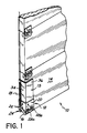
- FIG. 1 is a fragmentary perspective view of the garage door bottom bracket attached to a multipanel, hinged garage door;
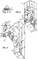
- FIG. 2 is a perspective view of the garage door bottom bracket attached to the garage door bottom panel;
- FIG. 3 is a sectional view taken on line 3-3 of FIG. 2; and
- FIG. 4 is a perspective view, partially broken away, of the garage door bottom bracket and garage door bottom panel; and
- FIG. 5 is a perspective view, partially broken away. of an alternate embodiment of the garage door bottom bracket and garage door bottom panel.
- Referring first to FIG. 1 of the drawings, the presently preferred embodiment of the garage door
bottom bracket 12 is shown attached to theend stile 15 which is in turn fixedly secured to abottom panel 14 of a multipanel, hingedgarage door 10. However, it should be recognized that thebracket 12 could be releasably secured directly to a garage doorbottom panel 14 without use of anend stile 15. Secured to thebottom bracket 12 is astandard door roller 16 for guiding thegarage door 10 during opening and closing, and a lift spring 18 for assisting in opening and closing the door. The tension in the lift spring 18 is at its maximum when the door is in the closed position and is at its minimum when the door is in the open position. - As shown in FIGs. 2 and 4, the
bottom bracket 12 is comprised of a generally L-shaped flange 20. This flange 20 overlays a part of the back 36 andside 34 of the garagedoor end stile 15. It is preferred that this flange be formed from a single metal sheet, although two bonded sheets could be used. - A
device 24 is provided for attaching the lift spring 18 directly or through a cable to thebottom bracket 12. Thepreferred device 24 has an elongatedcylindrical body 50 with anenlarged head 52. Where ametal bracket 12 is employed, thedevice 24 is secured to a metal flange 20 by welding or swaging at a location formed in the flange for that purpose. Of course, theentire bottom bracket 12 may be molded in one piece, but presently where thedevice 24 is formed independently of the flange, the manufacturing process may be simplified to reduce the cost of thebracket 12. - The
bracket 12 also secures a standard garagedoor track roller 16 by means of tworings 28a, 28b formed from the surface of the flange 20 that overlays the back of the garagedoor end stile 15. Theserings 28a, 28b are made substantially perpendicular to the flange surface from which they are formed to decrease the complexity of manufacture and ensure that theroller 16 will remain secured to thebottom bracket 12. -
Slots 26 are formed in thebottom bracket 12 and holes 32 are formed in theend stile 15 for passage of screws, bolts, orother fastening devices 33. For a traditional bracket, typically around three to five screws or bolts have been necessary to secure the bracket to the garage door. With the present invention, this number has been reduced to two, although additional fastening devices could be used. Theslots 26 can be in either surface of the flange, but the preferred location is in theback surface 19 rather than theside surface 21. - The preferred means for preventing the
bottom bracket 12 from separating from the garagedoor end stile 15 when the bracket is connected to the lift spring under tension includesmale projections 22 on thebottom bracket 12 and corresponding female receptacles 30 on the garage door end stile 15 (note that thebottom bracket 12 could be secured directly to thebottom panel 14, but it is preferred to secure it to anend stile 15 which is fixedly secured to the bottom panel 14). Theseprojections 22 and receptacles 30 interlock to secure thebottom bracket 12 to the garagedoor end stile 15. - Although any appropriate structure for interlocking the bracket and garage door may be used (i.e., an interlocking dove-tail structure), the preferred structure is a "keyhole" arrangement in which a female receptacle 30 comprises a bulbous or
enlarged opening 44 with anarrow slot 46 extending therefrom. The correspondingmale projection 22 comprises anarrow throat 42 and abulbous head 40. To interlock the components, the male projection is inserted into the female receptaclebulbous opening 44. Then themale projection 22 is moved relative to the female receptacle 30 such that the male projectionnarrow throat 42 enters the female receptaclenarrow slot 46, interlocking the components. The extent of this sliding interference fit is determined by the length of the female receptaclenarrow slot 46. - To ensure that the keyhole interlocking structure prevents the
bottom bracket 12 from separating from the garage doorbottom panel 14 when the lift spring 18 is attached and under tension, the female receptaclenarrow slot 46 should extend from thebulbous opening 44 in a direction generally towards the force in the spring (vertically upward). This permits the tension in the spring to bias thebottom bracket 12 towards an interlocked position. - The disclosed invention is particularly advantageous for use on garage doors that are constructed from wood or thin sheets of metal or plastic. The "keyhole" 30 can be made by simply punching or cutting the keyhole shape into the sheet from which the end stile 15 (if one is used) and door are formed. No special provisions are required to accommodate the male projection bulbous head when the bracket is interlocked with the garage door because the head merely rests behind the thin wall in the door's hollow cavity.
- The
male projection 22 is preferably integrally formed with thebracket 12. Referring to FIG. 3, themale projection 22 is constructed by stamping it out of the wall of thebottom bracket 12. This has the advantage of rendering themale projection 22 permanently affixed to the bracket and also simplifies the manufacturing process. Themale projection 22 is formed by first cutting two outlines in thebracket side wall 21. These outlines are mirror images of each other separated by a width substantially equal to the width of the female receptaclenarrow slot 46. The outline consists of an arc having two lines parallel to the line of reflection emanating from the endpoints. The center of these outlines is then pushed inward a distance substantially equal to the thickness of thebottom bracket 12 and garagedoor end stile 15; thebottom bracket 12 and garagedoor stile wall 34; or thebottom bracket 12, garagedoor end stile 15, and garagedoor side wall 34 combined depending upon the type of door used. The result is a male projection having abulbous head 40 and a narrow body consisting of atab 42 at either end of thebulbous head 40. - An alternate embodiment, shown in FIG. 5, is preferable for use on solid wooden garage doors, but may be used for both metal and plastic doors. In this embodiment, the
male projections 62 are secured directly to thestile surface 68 of the garage doorbottom panel 14. It is preferred that themale projections 62 be screwed directly onto thebottom panel 14, but any means for fixedly securing themale projections 62 may be used. Thefemale receptacles 70 are located on thebracket side wall 21. Themale projections 62 have a bulbous head 64 and narrow throat 66 that mate with thebulbous opening 72 andnarrow slot 74 of thefemale receptacles 70. In this embodiment, thenarrow slot 74 should extend from thebulbous opening 72 in a direction generally away from the force in the door lift spring 18 (FIG. 1) to ensure that the interlocking structure prevents thebottom bracket 12 from separating from the garage doorbottom panel 14. This arrangement permits the tension in the spring to bias thebottom bracket 12 towards an interlocked position. - Any number of interlocking
male projections 22 and female receptacles 30 can be used, but two are preferred. Also, it is preferred that the female receptacles be on theside 34 of the garage door. This places the interlocking components substantially in line with the door lift spring 18. - In use, the
bottom bracket 12 is placed onto the garagedoor end stile 15 by inserting themale projections 22 into the female receptacles 30. Then thebottom bracket 12 is moved relative to the garage door in the direction of the female receptaclenarrow throat 46 to the full extent of the interference fit. The screws, bolts orother fastening devices 33 are then secured to thebottom bracket 12 and the garagedoor end stile 15/bottom panel 14. At this point, the door lift spring 18 andtrack roller 16 are attached to thebottom bracket 12. If thefastening devices 33 are subsequently removed while the door lift spring 18 is attached to thebottom bracket 12, the male/female interlocking devices 22, 30 prevent thebottom bracket 12 from separating from the garage door end stile/bottom panel 14. Thus, the potentially catastrophic separation of the bottom bracket from the door under spring tension has been overcome by the principles of this invention.
Claims (18)
- An overhead garage door bottom bracket assembly for use at the bottom (14) of an overhead garage door (10) in assisting door lift in a spring tensioned system comprising a garage door bottom bracket (12), first means (26, 33) for releasably securing the bracket (12) to the door bottom (14) and second means (24) for connecting the bracket (12) to a door lifting spring (18) under tension, characterised in that third means (22, 70) is provided on the bracket (12) for releasably interlocking the bracket (12) to the door (10), the third means (22, 70) being adapted to interlock the bracket (12) with the door (10) when the bracket (12) is connected to the lift spring (18) under tension and/or the first means (26, 33) secure the bracket (12) to the door bottom (14) and to be easily releasable from the door bottom (14) when the first means (26, 33) no long secure the bracket thereto and the bracket (12) is not connected to the lift spring (18) under tension.
- An assembly as claimed in Claim 1, wherein the third means comprises at least one male protrusion (22) on the bracket (12) for interlocking the bracket to at least one female receptacle (30) on the door bottom by sliding interference fit.
- An assembly as claimed in Claim 2, wherein the male protrusion (22) has a narrow throat (42) and a bulbous head (40) adapted to be received by a female receptacle (30) on the door bottom.
- An assembly as claimed in Claim 1, wherein the third means comprises at least one female receptacle (70) on the bracket (12) for interlocking the bracket to at least one male protrusion (62) on the door bottom by sliding interference fit.
- An assembly as claimed in Claim 4, wherein the female receptacle (70) has a bulbous opening (72) and a narrow slot (74) adapted to receive the male protrusion (62) on the door bottom.
- An assembly as claimed in any preceding Claim, wherein the bottom bracket (12) comprises one piece (20) having two intersecting planar surfaces (19, 21) that are substantially perpendicular to one another and a pair of rings (28a, 28b) integrally formed from and substantially perpendicular to one of the planar surfaces (19, 21) for securing a standard door roller (16) to the bottom bracket (12).
- An assembly as claimed in Claim 6 when dependent on Claim 2 or Claim 3, wherein one of the planar surfaces (19) includes at least one slot (26) either forming part of the first means or adapted to permit the first means (33) to releasably secure the bracket (12) to the door bottom and the other of the planar surfaces (21) includes the male protrusions (22) and the second means (24) integrally formed therewith.
- An assembly as claimed in any preceding Claim, wherein the first means comprises a flange (20) with an aperture (26) for at least one threaded fastening device (33).
- An assembly as claimed in any preceding Claim, wherein the second means (24) comprises an elongated body (50) extending from the bracket (12) having an enlarged head (52) for securing the spring (18).
- An overhead garage door bottom bracket assembly for use at the bottom (14) of an overhead garage door (10) in assisting door lift in a spring tensioned system comprising first and second substantially perpendicularly intersecting planar surfaces (19, 21), a ring (28a, 28b) substantially perpendicular to the first planar surface (19) for securing a standard door roller (16) to the bottom bracket (12), at least one slot (26) in the first planar surface (19) to permit passage of at least one threaded fastening device (33) for releasably securing the bottom bracket (12) to the garage door (10) and an elongated body (50) extending from the second planar surface (21) with an end (52) for securing the bracket (12) to a door lifting spring (16) under tension, characterised in that the ring (28a, 28b) is formed from the first planar surface (19) and in that the assembly includes at least one male protrusion (22) having a narrow throat (42) and a bulbous head (40) on the second planar surface (21) for interlocking the bottom bracket (12) to at least one female receptacle (30) on the door bottom (14) through sliding interference fit thereby preventing the bracket (12) from releasing from the door bottom (14) when the bracket (12) is secured to the spring (16) under tension.
- An overhead garage door bottom bracket assembly for use at the bottom (14) of an overhead garage door (10) in assisting door lift in a spring tensioned system comprising first and second substantially perpendicularly intersecting planar surfaces (19, 21), a ring (28a, 28b) substantially perpendicular to the first planar surface (19) for securing a standard door roller (16) to the bottom bracket (12), at least one slot (26) in the first planar surface (19) to permit passage of at least one threaded fastening device (33) for releasably securing the bottom bracket (12) to the garage door (10) and an elongated body (50) extending from the second planar surface (21) with an end (52) for securing the bracket (12) to a door lifting spring (16) under tension, characterised in that the ring (28a, 28b) is formed from the first planar surface (19) and in that the assembly includes at least one female receptacle (70) having a bulbous opening (72) and a narrow slot (74) on the second planar surface (21) for interlocking the bottom bracket (12) to at least one male protrusion (62) on the door bottom (14) through sliding interference fit thereby preventing the bracket (12) from releasing from the door bottom (14) when the bracket (12) is secured to the spring (16) under tension.
- An overhead garage door bottom bracket assembly for assisting the door lift in a spring tensions system comprising a garage door bottom panel (14), and a garage door bottom bracket (12) having first and second substantially perpendicularly intersecting planar surfaces (19, 21), a ring (28a, 28b) substantially perpendicular to the first planar surface (19) for securing a standard door roller (16) thereto, at least one slot (26) in the first planar surface (19) to permit passage of at least one threaded fastening device (33) for releasably securing the bracket (12) to the bottom panel (14) and an elongated body (50) extending from the second planar surface (21) for securing the bracket (12) to a door lifting spring (18) under tension, characterised in that the ring (28a, 28b) is formed from the first planar surface (19) and in that the assembly includes means (22, 70) for releasably interlocking the bracket (12) to the door bottom (14), the means (22, 70) being adapted to interlock the bracket (12) with the door bottom (14) when the bracket is connected to the lift spring under tension and/or the bracket (12) is releasably secured to the bottom panel (14) and to be easily releasable from the door bottom (14) when the first means (26, 33) no longer secure the bracket thereto and the bracket (12) is not connected to the lift spring (18) under tension.
- A bracket assembly as claimed in Claim 12, wherein the means for preventing the bracket (12) from releasing the bottom panel comprises at least one male protrusion (22) on the bracket (12), and at least one female receptacle (30) on the bottom panel (14) for interlocking the bracket (12) to the bottom panel (14) by sliding interference fit.
- A bracket assembly as claimed in Claim 13, wherein the male protrusion (22) has a narrow throat (42) and bulbous head (40) and the female receptacle (30) has a bulbous opening (44) with a narrow slot (46) extending therefrom, the bulbous head (40) being adapted to be received by the bulbous opening (44), and the narrow throat (42) being adapted to be received by the narrow slot (46).
- A bracket assembly as claimed in either Claim 13 or Claim 14, wherein the female receptacle(s) (30) are located in the stile (15) of the bottom panel (14) and the male protrusions are located on the bracket second planar surface (21).
- A bracket assembly as claimed in Claim 12, wherein the means for preventing the bracket (12) from releasing the bottom panel (14) comprises at least one female receptacle (70) on the bracket (12), and at least one male protrusion (62) on the bottom panel (14) for interlocking the bracket (12) to the bottom panel (14) by sliding interference fit.
- A bracket assembly as claimed in Claim 16, wherein the male protrusion (62) has a narrow throat (66) and bulbous head (64) and the female receptacle (70) has a bulbous opening (72) with a narrow slot (74) extending therefrom, the bulbous head (64) being adapted to be received by the bulbous opening (72), and the narrow throat (66) adapted to be received by the narrow slot (74).
- A bracket assembly as claimed in either Claim 17 or Claim 18, wherein the male protrusions (62) are located on the stile (15) of the bottom panel (14) and the female receptacles (70) are located in the bracket second planar surface (21).
Applications Claiming Priority (3)
| Application Number | Priority Date | Filing Date | Title |
|---|---|---|---|
| US08/060,254 US5404927A (en) | 1993-05-12 | 1993-05-12 | Overhead garage door bottom bracket |
| US60254 | 1993-05-12 | ||
| PCT/US1994/004647 WO1994027016A1 (en) | 1993-05-12 | 1994-04-28 | Overhead garage door bottom bracket |
Publications (2)
| Publication Number | Publication Date |
|---|---|
| EP0698168A1 EP0698168A1 (en) | 1996-02-28 |
| EP0698168B1 true EP0698168B1 (en) | 1996-12-18 |
Family
ID=22028340
Family Applications (1)
| Application Number | Title | Priority Date | Filing Date |
|---|---|---|---|
| EP94920659A Expired - Lifetime EP0698168B1 (en) | 1993-05-12 | 1994-04-28 | Overhead garage door bottom bracket |
Country Status (6)
| Country | Link |
|---|---|
| US (1) | US5404927A (en) |
| EP (1) | EP0698168B1 (en) |
| AU (1) | AU7136994A (en) |
| CA (1) | CA2162278C (en) |
| DE (1) | DE69401211T2 (en) |
| WO (1) | WO1994027016A1 (en) |
Families Citing this family (35)
| Publication number | Priority date | Publication date | Assignee | Title |
|---|---|---|---|---|
| US5522446A (en) * | 1994-06-15 | 1996-06-04 | Wayne-Dalton Corp. | Sectional overhead door |
| US5918660A (en) * | 1996-02-12 | 1999-07-06 | Crawford, Iii; Dan S. | Repair and reinforcement apparatus for overhead door |
| EP0825320A3 (en) * | 1996-08-19 | 1998-05-20 | Windsor Door | Door panel mating assembly |
| US6112464A (en) * | 1997-01-29 | 2000-09-05 | Overhead Door Corporation | Bracket for counterbalanced garage door |
| US5992497A (en) * | 1997-04-25 | 1999-11-30 | Clopay Building Products Company, Inc. | Slip and lock connection system |
| US6082046A (en) * | 1998-02-25 | 2000-07-04 | Simmons; Kevin A. | Overhead door sensor mounting bracket |
| US6098697A (en) * | 1998-06-12 | 2000-08-08 | Overhead Door Corporation | Sectional door with pinch resistant hinge between door sections |
| US6047761A (en) * | 1998-09-08 | 2000-04-11 | Clopay Building Products Company Inc. | Universal overhead door system |
| US6082430A (en) * | 1999-04-07 | 2000-07-04 | Amarr Garage Doors | Garage door safety bracket |
| US6547292B1 (en) * | 2000-03-13 | 2003-04-15 | Hi-Fold Door Corporation | Over center door closing mechanism |
| US6742564B2 (en) | 2000-04-12 | 2004-06-01 | Martin Door Manufacturing, Inc. | Spring force safety locking system for sectional doors |
| US6401793B1 (en) * | 2000-04-12 | 2002-06-11 | Martin Door Manufacturing, Inc. | Spring force safety locking system for sectional doors |
| US6263948B1 (en) | 2000-04-19 | 2001-07-24 | Overhead Door Corporation | Bottom bracket for upward acting door |
| US6588482B2 (en) | 2001-07-19 | 2003-07-08 | Raynor Garage Doors | Cable attachment bracket for articulating garage door panels |
| US7059379B2 (en) * | 2002-04-25 | 2006-06-13 | Clopay Building Products R&D Company, Inc. | Low head room overhead door system with adjustable short radius track section |
| US6907641B1 (en) * | 2003-06-17 | 2005-06-21 | James P Liles | Reinforcement bracket for a bi-fold closet door |
| US7234502B2 (en) * | 2003-12-26 | 2007-06-26 | O'malley James J | Overhead door apparatus with enclosed counterbalance mechanism |
| US8091607B2 (en) * | 2006-05-05 | 2012-01-10 | Anthony George Aquilina | Garage door bracket assembly with slidable roller housing |
| US8037576B2 (en) * | 2007-08-16 | 2011-10-18 | 4Front Engineered Solutions, Inc. | Overhead doors and associated track and guide assemblies for use with same |
| ES2592530T3 (en) | 2011-06-17 | 2016-11-30 | Fiberweb, Llc | Multi-layer vapor permeable article, substantially waterproof |
| CN103747955B (en) | 2011-06-23 | 2017-03-22 | 纤维网公司 | Vapor permeable, substantially water impermeable multilayer article |
| WO2012178027A2 (en) | 2011-06-23 | 2012-12-27 | Fiberweb, Inc. | Vapor-permeable, substantially water-impermeable multilayer article |
| US9765459B2 (en) | 2011-06-24 | 2017-09-19 | Fiberweb, Llc | Vapor-permeable, substantially water-impermeable multilayer article |
| US8893764B2 (en) | 2012-08-08 | 2014-11-25 | 4Front Engineered Solutions, Inc. | Overhead door decelerators and associated devices, systems, and methods |
| US9234387B2 (en) * | 2013-09-24 | 2016-01-12 | Whiting Door Manufacturing Corp. | Snubber devices for use in roll-up door assemblies |
| WO2019067288A1 (en) * | 2017-09-26 | 2019-04-04 | Aurora Systems Inc. | Securely attachable extension panels for doors |
| US12258800B2 (en) | 2020-05-01 | 2025-03-25 | Clopay Corporation | Laminate panel and overhead sectional door panel with laminate panels and a universal fabric hinge |
| US12258801B2 (en) | 2021-07-01 | 2025-03-25 | Assa Abloy Entrance Systems Ab | Offset roller carrier and bottom bracket assembly |
| US12012803B2 (en) * | 2021-12-02 | 2024-06-18 | Thermo Traks Inc. | Seal for an overhead door |
| US12359481B2 (en) * | 2022-08-11 | 2025-07-15 | Overhead Door Corporation | Anchor system for a bracket of a movable barrier |
| US12345081B2 (en) * | 2022-08-11 | 2025-07-01 | Overhead Door Corporation | Lower bracket and anchor system for a movable barrier |
| CA3268811A1 (en) * | 2022-10-11 | 2024-04-18 | Clopay Corporation | Door stop mechanism |
| US20250137308A1 (en) * | 2023-10-31 | 2025-05-01 | Overhead Door Corporation | Anchor system with integrated cable pin |
| WO2025166425A1 (en) * | 2024-02-08 | 2025-08-14 | Tower Garage Doors Pty Ltd | A garage door and a bracket for a garage door |
| AU2025202188B1 (en) * | 2024-02-08 | 2025-05-22 | Tower Garage Doors Pty Ltd | A garage door and a bracket for a garage door |
Family Cites Families (21)
| Publication number | Priority date | Publication date | Assignee | Title |
|---|---|---|---|---|
| US857850A (en) * | 1907-02-07 | 1907-06-25 | Barcalo Mfg Co | Corner-fastening for bedsteads. |
| US1341068A (en) * | 1917-12-22 | 1920-05-25 | George W Zimmer | Corner-post fastener |
| GB207692A (en) * | 1922-11-17 | 1923-12-06 | George Gale And Sons Ltd | Improvements in or relating to joints or connections for bedsteads and the like |
| US2008959A (en) * | 1929-03-27 | 1935-07-23 | Clarence G Johnson | Sliding door construction |
| US2072514A (en) * | 1933-01-16 | 1937-03-02 | Ralston Steel Car Co | Sectional doorway |
| US2227571A (en) * | 1939-09-16 | 1941-01-07 | Henry B Clark | Two-section overhead door |
| US2291583A (en) * | 1940-05-27 | 1942-07-28 | Rowe Mfg Company | Overhead door construction |
| US2471197A (en) * | 1944-10-11 | 1949-05-24 | Henry B Clark | Bracket for mounting rollers on overhead doors |
| US2436006A (en) * | 1945-01-18 | 1948-02-17 | Better Bilt Door Company | Overhead door |
| US2442309A (en) * | 1946-01-31 | 1948-05-25 | Raynor Mfg Company | Overhead door construction |
| US2495672A (en) * | 1946-08-02 | 1950-01-24 | Stewart J Dautrick | Garage door |
| US2684846A (en) * | 1951-12-08 | 1954-07-27 | Overhead Door Corp | Pull rope for upwardly acting doors |
| US2694214A (en) * | 1954-01-04 | 1954-11-16 | Hammer Joseph | Overhead door system bracket |
| US3090427A (en) * | 1957-04-12 | 1963-05-21 | Overhead Door Corp | Upwardly acting door assembly |
| US3071400A (en) * | 1960-07-27 | 1963-01-01 | Bellock Jack | Releasable locking joint structures |
| US3334681A (en) * | 1964-07-06 | 1967-08-08 | Overhead Door Corp | Upwardly acting doors |
| US3354934A (en) * | 1964-08-05 | 1967-11-28 | Garland Mfg Company | Garage door |
| US3412780A (en) * | 1966-08-02 | 1968-11-26 | Overhead Door Corp | Slack cable take-up |
| US3548425A (en) * | 1968-05-01 | 1970-12-22 | Toby Goldstein | Abutment interlock mechanism |
| CA1114237A (en) * | 1975-12-15 | 1981-12-15 | Bruce E. Olson | Attachment for an overhead door |
| US4158998A (en) * | 1976-05-12 | 1979-06-26 | The Mead Corporation | Shelf support structure |
-
1993
- 1993-05-12 US US08/060,254 patent/US5404927A/en not_active Expired - Lifetime
-
1994
- 1994-04-28 DE DE69401211T patent/DE69401211T2/en not_active Expired - Fee Related
- 1994-04-28 EP EP94920659A patent/EP0698168B1/en not_active Expired - Lifetime
- 1994-04-28 WO PCT/US1994/004647 patent/WO1994027016A1/en not_active Ceased
- 1994-04-28 CA CA002162278A patent/CA2162278C/en not_active Expired - Lifetime
- 1994-04-28 AU AU71369/94A patent/AU7136994A/en not_active Abandoned
Also Published As
| Publication number | Publication date |
|---|---|
| DE69401211D1 (en) | 1997-01-30 |
| WO1994027016A1 (en) | 1994-11-24 |
| CA2162278A1 (en) | 1994-11-24 |
| EP0698168A1 (en) | 1996-02-28 |
| DE69401211T2 (en) | 1997-04-10 |
| AU7136994A (en) | 1994-12-12 |
| US5404927A (en) | 1995-04-11 |
| CA2162278C (en) | 1999-02-16 |
Similar Documents
| Publication | Publication Date | Title |
|---|---|---|
| CA2162278C (en) | Overhead garage door bottom bracket | |
| US5399005A (en) | Stackable locking display and dispensing structure | |
| US5193308A (en) | Snap-in hinge for doors with hollow metal frames | |
| US4631894A (en) | Hardware for panel doors | |
| RU2153054C1 (en) | Device for actuation of protective housing locking bolt for automatic bank apparatus | |
| US5570917A (en) | Home security interlocking hinges and striker plates | |
| US5490306A (en) | Hinge and security cover plate assembly | |
| US4807687A (en) | Security door system | |
| US20030029580A1 (en) | Cable attachment bracket for articulating garage door panels | |
| CA2343249C (en) | Vending machine with quick-release door | |
| US4629265A (en) | Cabinet construction | |
| EP1165919B1 (en) | Garage door safety bracket | |
| US5832671A (en) | Security closure | |
| US5970756A (en) | Dead bolt lock assembly cover | |
| US7024820B1 (en) | Sliding door security assembly | |
| US4850287A (en) | Safe with double sliding door | |
| US5606880A (en) | Quick-release lock retaining bracket method and apparatus | |
| US4823510A (en) | Security door system | |
| US4098025A (en) | Door assembly and method of construction same | |
| US4704767A (en) | Security door hinge system with locking elements | |
| US4573722A (en) | Locker handle assembly | |
| US12291895B2 (en) | Mounting brace assembly for a pull handle assembly | |
| GB2111586A (en) | Staples for padlocks | |
| US4902054A (en) | Safety device for disabling a screen door latching mechanism | |
| CA1110029A (en) | Panel mounting assembly |
Legal Events
| Date | Code | Title | Description |
|---|---|---|---|
| PUAI | Public reference made under article 153(3) epc to a published international application that has entered the european phase |
Free format text: ORIGINAL CODE: 0009012 |
|
| 17P | Request for examination filed |
Effective date: 19951108 |
|
| AK | Designated contracting states |
Kind code of ref document: A1 Designated state(s): DE FR GB |
|
| GRAG | Despatch of communication of intention to grant |
Free format text: ORIGINAL CODE: EPIDOS AGRA |
|
| GRAH | Despatch of communication of intention to grant a patent |
Free format text: ORIGINAL CODE: EPIDOS IGRA |
|
| 17Q | First examination report despatched |
Effective date: 19960604 |
|
| GRAH | Despatch of communication of intention to grant a patent |
Free format text: ORIGINAL CODE: EPIDOS IGRA |
|
| GRAA | (expected) grant |
Free format text: ORIGINAL CODE: 0009210 |
|
| AK | Designated contracting states |
Kind code of ref document: B1 Designated state(s): DE FR GB |
|
| ET | Fr: translation filed | ||
| REF | Corresponds to: |
Ref document number: 69401211 Country of ref document: DE Date of ref document: 19970130 |
|
| PLBE | No opposition filed within time limit |
Free format text: ORIGINAL CODE: 0009261 |
|
| STAA | Information on the status of an ep patent application or granted ep patent |
Free format text: STATUS: NO OPPOSITION FILED WITHIN TIME LIMIT |
|
| 26N | No opposition filed | ||
| REG | Reference to a national code |
Ref country code: GB Ref legal event code: 732E |
|
| REG | Reference to a national code |
Ref country code: FR Ref legal event code: TP |
|
| REG | Reference to a national code |
Ref country code: GB Ref legal event code: IF02 |
|
| PGFP | Annual fee paid to national office [announced via postgrant information from national office to epo] |
Ref country code: GB Payment date: 20080317 Year of fee payment: 15 |
|
| PGFP | Annual fee paid to national office [announced via postgrant information from national office to epo] |
Ref country code: DE Payment date: 20080430 Year of fee payment: 15 |
|
| PGFP | Annual fee paid to national office [announced via postgrant information from national office to epo] |
Ref country code: FR Payment date: 20080403 Year of fee payment: 15 |
|
| GBPC | Gb: european patent ceased through non-payment of renewal fee |
Effective date: 20090428 |
|
| REG | Reference to a national code |
Ref country code: FR Ref legal event code: ST Effective date: 20091231 |
|
| PG25 | Lapsed in a contracting state [announced via postgrant information from national office to epo] |
Ref country code: DE Free format text: LAPSE BECAUSE OF NON-PAYMENT OF DUE FEES Effective date: 20091103 |
|
| PG25 | Lapsed in a contracting state [announced via postgrant information from national office to epo] |
Ref country code: GB Free format text: LAPSE BECAUSE OF NON-PAYMENT OF DUE FEES Effective date: 20090428 Ref country code: FR Free format text: LAPSE BECAUSE OF NON-PAYMENT OF DUE FEES Effective date: 20091222 |