EP0697943B1 - Improvements in a roof tile making machine - Google Patents
Improvements in a roof tile making machine Download PDFInfo
- Publication number
- EP0697943B1 EP0697943B1 EP94916202A EP94916202A EP0697943B1 EP 0697943 B1 EP0697943 B1 EP 0697943B1 EP 94916202 A EP94916202 A EP 94916202A EP 94916202 A EP94916202 A EP 94916202A EP 0697943 B1 EP0697943 B1 EP 0697943B1
- Authority
- EP
- European Patent Office
- Prior art keywords
- pallets
- tile
- mortar
- making machine
- hopper
- Prior art date
- Legal status (The legal status is an assumption and is not a legal conclusion. Google has not performed a legal analysis and makes no representation as to the accuracy of the status listed.)
- Expired - Lifetime
Links
- 239000004570 mortar (masonry) Substances 0.000 claims abstract description 53
- 238000000034 method Methods 0.000 claims abstract description 11
- 238000004519 manufacturing process Methods 0.000 claims abstract description 9
- 238000005056 compaction Methods 0.000 claims description 28
- 238000005728 strengthening Methods 0.000 claims description 12
- 238000011144 upstream manufacturing Methods 0.000 claims description 9
- 238000005520 cutting process Methods 0.000 claims description 5
- 239000008188 pellet Substances 0.000 claims 1
- 230000002787 reinforcement Effects 0.000 abstract 3
- 238000012986 modification Methods 0.000 description 4
- 230000004048 modification Effects 0.000 description 4
- 230000003014 reinforcing effect Effects 0.000 description 4
- 239000000470 constituent Substances 0.000 description 2
- 238000013461 design Methods 0.000 description 2
- 230000015572 biosynthetic process Effects 0.000 description 1
- 239000000463 material Substances 0.000 description 1
- 238000003672 processing method Methods 0.000 description 1
- 238000012360 testing method Methods 0.000 description 1
- 230000000007 visual effect Effects 0.000 description 1
Images

Classifications
-
- B—PERFORMING OPERATIONS; TRANSPORTING
- B28—WORKING CEMENT, CLAY, OR STONE
- B28B—SHAPING CLAY OR OTHER CERAMIC COMPOSITIONS; SHAPING SLAG; SHAPING MIXTURES CONTAINING CEMENTITIOUS MATERIAL, e.g. PLASTER
- B28B1/00—Producing shaped prefabricated articles from the material
- B28B1/29—Producing shaped prefabricated articles from the material by profiling or strickling the material in open moulds or on moulding surfaces
-
- B—PERFORMING OPERATIONS; TRANSPORTING
- B28—WORKING CEMENT, CLAY, OR STONE
- B28B—SHAPING CLAY OR OTHER CERAMIC COMPOSITIONS; SHAPING SLAG; SHAPING MIXTURES CONTAINING CEMENTITIOUS MATERIAL, e.g. PLASTER
- B28B1/00—Producing shaped prefabricated articles from the material
- B28B1/14—Producing shaped prefabricated articles from the material by simple casting, the material being neither forcibly fed nor positively compacted
- B28B1/16—Producing shaped prefabricated articles from the material by simple casting, the material being neither forcibly fed nor positively compacted for producing layered articles
-
- B—PERFORMING OPERATIONS; TRANSPORTING
- B28—WORKING CEMENT, CLAY, OR STONE
- B28B—SHAPING CLAY OR OTHER CERAMIC COMPOSITIONS; SHAPING SLAG; SHAPING MIXTURES CONTAINING CEMENTITIOUS MATERIAL, e.g. PLASTER
- B28B13/00—Feeding the unshaped material to moulds or apparatus for producing shaped articles; Discharging shaped articles from such moulds or apparatus
- B28B13/02—Feeding the unshaped material to moulds or apparatus for producing shaped articles
-
- B—PERFORMING OPERATIONS; TRANSPORTING
- B28—WORKING CEMENT, CLAY, OR STONE
- B28B—SHAPING CLAY OR OTHER CERAMIC COMPOSITIONS; SHAPING SLAG; SHAPING MIXTURES CONTAINING CEMENTITIOUS MATERIAL, e.g. PLASTER
- B28B5/00—Producing shaped articles from the material in moulds or on moulding surfaces, carried or formed by, in or on conveyors irrespective of the manner of shaping
- B28B5/02—Producing shaped articles from the material in moulds or on moulding surfaces, carried or formed by, in or on conveyors irrespective of the manner of shaping on conveyors of the endless-belt or chain type
- B28B5/026—Producing shaped articles from the material in moulds or on moulding surfaces, carried or formed by, in or on conveyors irrespective of the manner of shaping on conveyors of the endless-belt or chain type the shaped articles being of indefinite length
- B28B5/028—Producing shaped articles from the material in moulds or on moulding surfaces, carried or formed by, in or on conveyors irrespective of the manner of shaping on conveyors of the endless-belt or chain type the shaped articles being of indefinite length the moulding surfaces being of definite length, e.g. succession of moving pallets, and being continuously fed
-
- Y—GENERAL TAGGING OF NEW TECHNOLOGICAL DEVELOPMENTS; GENERAL TAGGING OF CROSS-SECTIONAL TECHNOLOGIES SPANNING OVER SEVERAL SECTIONS OF THE IPC; TECHNICAL SUBJECTS COVERED BY FORMER USPC CROSS-REFERENCE ART COLLECTIONS [XRACs] AND DIGESTS
- Y10—TECHNICAL SUBJECTS COVERED BY FORMER USPC
- Y10S—TECHNICAL SUBJECTS COVERED BY FORMER USPC CROSS-REFERENCE ART COLLECTIONS [XRACs] AND DIGESTS
- Y10S264/00—Plastic and nonmetallic article shaping or treating: processes
- Y10S264/31—Processes of making tile and tile-like surfaces
Definitions
- This invention is concerned with improvements in or relating to a roof tile making machine and its method of operation.
- Concrete roof tiles are in the main formed by the well known roller and slipper method in which tile pallets are fed seriatim beneath the mortar hopper of a tile making machine, whereat when the machine is in use, mortar is fed by a packshaft,roller and slipper onto the pallets to form a continuous ribbon thereon. Downstream of the mortar hopper, a cutting mechanism of the tile making machine is operated to cut the ribbon of mortar to form discrete "green state” tiles on the individual pallets which "green state” tiles are thereafter cured by conventional means.
- the upper surfaces of the tiles so formed are generated by the roller and slipper and may therefore be of any desired profile across the tiles so formed.
- the tiles may have a so-called "Bold Roll” or "Roman” profile.
- the under-surfaces of the tiles are formed by the pallets, that is, the surfaces of the pallets are shaped with recesses and channels to form hanging nibs, strengthening ribs and downwardly facing interlocking sidelock features of the tiles.
- the strengthening ribs have a depth which is self-defeating in relation to their purposive intent which is to strengthen the tiles. Tests effected on cured tile sections have consistently indicated that the thin body sections have greater strength than the ribs or that size for size the proportion of the tile's strength supplied by the ribs is disproportionate to their depth.
- a tile making machine is disclosed in GB 2183530B which machine is specifically intended for use in making verge tiles having a "Bold Roll" profile across the width of the tile. From the disclosure and drawings of GB 2183530B, it is apparent that no provision is made for ensuring that all sections of the tiles made on such a machine are evenly compacted.
- the present invention seeks to overcome or at least mitigate the disadvantages of the prior art concrete roof tiles.
- the present invention provides a tile making machine comprising a hopper provided with a packshaft, roller and slipper, said packshaft being effective, when the machine is in use and tile pallets are fed seriatim beneath said hopper, to direct mortar onto said pallets as they pass beneath the roller and slipper to form a continuous ribbon of mortar on said pallets, characterised in that the tile making machine also comprises compaction means upstream of said packshaft, roller and slipper, which compaction means comprises a primary compaction device which, when the machine is in use and tile pallets are fed as aforesaid, directs and compacts mortar onto and/or into selected portions only of said pallets said selected portions forming, inter alia, longitudinal strengthening ribs in finished tiles.
- the present invention also provides a tile making machine according to the preceding paragraph further characterised in that said compacting means also comprises a secondary compaction device wherein, when the machine is in use, and after the primary compaction device has directed and compacted mortar onto and/or into the selected portions of the pallets as aforesaid, the secondary compaction device further compacts the mortar in said selected portions only of the pallets as the pallets pass therebeneath to fully compact the mortar of the portions forming the longitudinal strengthening ribs in the finished tile as aforesaid.
- the primary compaction device comprises a multi-tined wheel arranged in use to overlie selected portions only of said pallets as aforesaid, the multi-tined wheel conveniently having an effective width corresponding to the width of the longitudinal strengthening ribs formed by said selected portions only of the pallets.
- the present invention also provides a tile making machine according to the last two preceding paragraphs wherein the secondary compaction device comprises a thin gauge blade element extending parallel to the direction of feed of the pallets fed seriatim beneath said hopper, the blade element comprising a blade portion arranged to lie in or towards a nip portion provided in use of the tile making machine and formed between a circumferential path generated by the tines of the multi-tined wheel and co-planar upper surface portions of said pallets fed therebeneath.
- the secondary compaction device comprises a thin gauge blade element extending parallel to the direction of feed of the pallets fed seriatim beneath said hopper, the blade element comprising a blade portion arranged to lie in or towards a nip portion provided in use of the tile making machine and formed between a circumferential path generated by the tines of the multi-tined wheel and co-planar upper surface portions of said pallets fed therebeneath.
- said blade element has an effective length of 0.1 to 0.3 the length of tile pallets used therewith.
- the compaction means is located in said hopper upstream of the packshaft, roller and slipper, as aforesaid.
- the compaction means may be located in a secondary hopper located upstream of said hopper.
- the present invention also conveniently provides a process for the manufacture of concrete roof tiles in a conventional tile making machine provided with a hopper supporting a packshaft, a roller and a slipper all of known configuration, said process comprising the steps of :
- the present invention thus comprises a unique tile making machine 4 which enables a novel method of making concrete roof tiles 2 to be effected so that all sections of the tiles produced therein are subjected to uniform or substantially uniform compaction forces resulting in a uniformity of mortar density in the finished product which, when cured, has a uniform strength or substantially so.
- the tile making machine 4 comprises twin hoppers 8 and 10 located in series overlying a pallet conveyor 12.
- the conveyor 12 is of conventional design, is supported on floor mounted columns 12a and 12b and comprises support rails 12c on which pallets P are supported as they pass seriatim beneath the hoppers 8 and 10.
- the hopper 8 is also of conventional design and provides support for a roller 13, a slipper 14 and a pack shaft 16.
- the hopper 10 is located upstream of the hopper 8 and comprises a shaft 18 located towards a front wall 20 thereof.
- the shaft 18 provides support for a primary compaction device comprised of two tined wheels 18a only one of which is shown in the drawings, the purpose of which tined wheels will be made clear hereinafter.
- the front wall 20 provides support for a secondary compaction device comprised of a blade element 22 the purpose of which element 22 will also be made clear hereinafter.
- each hopper 8 and 10 Located above each hopper 8 and 10 are respective material feed conveyors 34 and 36 for feeding mortar to said hoppers, see Figure 1.
- the tile making machine Downstream of the hopper 8, the tile making machine is provided with a conventional tile cutting knife 38 which is mounted for reciprocal vertical and longitudinal movement on a knife carriage 40 illustrated schematically in Figure 1.
- the tile making machine also comprises a pallet spacing conveyor 42 which is arranged beneath the conveyor 12 and adjacent the knife carriage 40 for a purpose also to be made clear hereinafter.
- the recesses 19 enable the formation of the strengthening ribs of a roof tile and, as can be seen in Figure 5, the tined wheels 18a each overlie a respective one of the recesses 19, the wheels 18a each providing support for an array of tines 18b in three equi-spaced memorid ranks around the circumference of the wheel 18a.
- the blade element 22 which is between 0.1 and 0.3 the length of a tile pallet P acts in part as a conventional slipper and further compacts the mortar into the recesses 19 to facilitate the manufacture of concrete roof tiles with reinforcing ribs which are fit for purpose.
- the pallets P thereafter proceed beneath the hopper 8 whereat the mortar therein is compacted by the packshaft 16, the rollers 13 and the slipper 14 onto the pallets P and the pre-formed reinforcing ribs to form a ribbon 46 of mortar on the pallets P in known manner.
- the ribbon 46 is thereafter cut by the knife 38 of the tile cutting arrangement whereupon trailing ends of the pallets P are engaged by drive elements 52 of the conveyor 42 whereby the "green state" tiles 2 on their associated pallets P are conveyed to racking devices prior to transportation to curing chambers.
- the tile making machine may be modified as shown in Figure 2 in which the twin hopper arrangement is replaced by a hybrid hopper 9 having first and second sections 9a and 9b corresponding to hoppers 10 and 8 respectively of Figure 1.
- the sections 9a and 9b are separated by a divider plate 9c which supports the blade element 22 at its lower end 9d, see Figure 2. All other features are essentially the same as those of Figure 1 and they have, therefore, been accorded like reference characters.
- the tile making machine may also be modified as shown in Figure 3 in which a unitary hopper 11 comprises support for the roller 13, slipper 14, packshaft 16, tined wheel 18a and the blade element 22.
- a unitary hopper 11 comprises support for the roller 13, slipper 14, packshaft 16, tined wheel 18a and the blade element 22.
- guide plates 20a and 20b may be provided on each side of the wheels 18a and 18b to direct mortar into the recesses 19 of the pallets P.
- a screw augur 60 may be provided adjacent the wall 20 as shown in Figure 6 which augur 60 feeds mortar to a collection box (not shown) for recirculation to the top of the hopper 10.
- tiles made using the three modified arrangements of Figures 1, 2 and 3 may on the one hand be comprised of different mortars or on the other hand be of the same mortar throughout their thicknesses.
- the mortar delivered by conveyor 36 to the hopper 10 or the section 9a of the hopper 9 may, if required, be made of different constituents or have varying amounts of the same constituents in areas to assist the compaction of the reinforcing ribs of tiles made therein.
- the Figure 3 modification lends itself for use with a single mortar fed by the conveyor 34.
Landscapes
- Engineering & Computer Science (AREA)
- Manufacturing & Machinery (AREA)
- Chemical & Material Sciences (AREA)
- Ceramic Engineering (AREA)
- Mechanical Engineering (AREA)
- Press-Shaping Or Shaping Using Conveyers (AREA)
- Devices For Post-Treatments, Processing, Supply, Discharge, And Other Processes (AREA)
- Roof Covering Using Slabs Or Stiff Sheets (AREA)
- Machines For Manufacturing Corrugated Board In Mechanical Paper-Making Processes (AREA)
- Devices For Checking Fares Or Tickets At Control Points (AREA)
- Finishing Walls (AREA)
- Preparation Of Clay, And Manufacture Of Mixtures Containing Clay Or Cement (AREA)
- Conveying And Assembling Of Building Elements In Situ (AREA)
- Panels For Use In Building Construction (AREA)
- Furnace Housings, Linings, Walls, And Ceilings (AREA)
- Shaping Of Tube Ends By Bending Or Straightening (AREA)
- On-Site Construction Work That Accompanies The Preparation And Application Of Concrete (AREA)
Abstract
Description
- This invention is concerned with improvements in or relating to a roof tile making machine and its method of operation.
- Concrete roof tiles are in the main formed by the well known roller and slipper method in which tile pallets are fed seriatim beneath the mortar hopper of a tile making machine, whereat when the machine is in use, mortar is fed by a packshaft,roller and slipper onto the pallets to form a continuous ribbon thereon. Downstream of the mortar hopper, a cutting mechanism of the tile making machine is operated to cut the ribbon of mortar to form discrete "green state" tiles on the individual pallets which "green state" tiles are thereafter cured by conventional means.
- The upper surfaces of the tiles so formed are generated by the roller and slipper and may therefore be of any desired profile across the tiles so formed. For example, the tiles may have a so-called "Bold Roll" or "Roman" profile.
- The under-surfaces of the tiles, on the other hand, are formed by the pallets, that is, the surfaces of the pallets are shaped with recesses and channels to form hanging nibs, strengthening ribs and downwardly facing interlocking sidelock features of the tiles.
- Often the strengthening ribs have a depth which is self-defeating in relation to their purposive intent which is to strengthen the tiles. Tests effected on cured tile sections have consistently indicated that the thin body sections have greater strength than the ribs or that size for size the proportion of the tile's strength supplied by the ribs is disproportionate to their depth.
- It is believed that this phenomenon is caused by the variations in compaction of the different sections of the tiles. For example, a thin body section is readily compacted to give a high strength for a particular cross-section and yet an adjacent strengthening rib formed under the same compacting pressures, applied by the same roller and slipper does not have the strength expected of it. Visual examination of the cross-section of such ribs by examination of the apparent porosity thereof has revealed that the compaction of the mortar is greatest towards the thin body portion of the tiles whilst it falls off towards the extremities of the ribs, that is the degree of compaction of the mortar in the ribs is apparently a function of the respective depths of the ribs.
- A tile making machine is disclosed in GB 2183530B which machine is specifically intended for use in making verge tiles having a "Bold Roll" profile across the width of the tile. From the disclosure and drawings of GB 2183530B, it is apparent that no provision is made for ensuring that all sections of the tiles made on such a machine are evenly compacted.
- The present invention seeks to overcome or at least mitigate the disadvantages of the prior art concrete roof tiles. Thus, the present invention provides a tile making machine comprising a hopper provided with a packshaft, roller and slipper, said packshaft being effective, when the machine is in use and tile pallets are fed seriatim beneath said hopper, to direct mortar onto said pallets as they pass beneath the roller and slipper to form a continuous ribbon of mortar on said pallets, characterised in that the tile making machine also comprises compaction means upstream of said packshaft, roller and slipper, which compaction means comprises a primary compaction device which, when the machine is in use and tile pallets are fed as aforesaid, directs and compacts mortar onto and/or into selected portions only of said pallets said selected portions forming, inter alia, longitudinal strengthening ribs in finished tiles.
- The present invention also provides a tile making machine according to the preceding paragraph further characterised in that said compacting means also comprises a secondary compaction device wherein, when the machine is in use, and after the primary compaction device has directed and compacted mortar onto and/or into the selected portions of the pallets as aforesaid, the secondary compaction device further compacts the mortar in said selected portions only of the pallets as the pallets pass therebeneath to fully compact the mortar of the portions forming the longitudinal strengthening ribs in the finished tile as aforesaid.
- Preferably in the tile making machine according to the last two preceding paragraphs, the primary compaction device comprises a multi-tined wheel arranged in use to overlie selected portions only of said pallets as aforesaid, the multi-tined wheel conveniently having an effective width corresponding to the width of the longitudinal strengthening ribs formed by said selected portions only of the pallets.
- The present invention also provides a tile making machine according to the last two preceding paragraphs wherein the secondary compaction device comprises a thin gauge blade element extending parallel to the direction of feed of the pallets fed seriatim beneath said hopper, the blade element comprising a blade portion arranged to lie in or towards a nip portion provided in use of the tile making machine and formed between a circumferential path generated by the tines of the multi-tined wheel and co-planar upper surface portions of said pallets fed therebeneath.
- Preferably in the tile making machine according to the last preceding paragraph said blade element has an effective length of 0.1 to 0.3 the length of tile pallets used therewith.
- Conveniently in a tile making machine according to any one of the last four preceding paragraphs the compaction means is located in said hopper upstream of the packshaft, roller and slipper, as aforesaid.
- Preferably in a tile making machine provided by the invention the compaction means may be located in a secondary hopper located upstream of said hopper.
- The present invention also conveniently provides a process for the manufacture of concrete roof tiles in a conventional tile making machine provided with a hopper supporting a packshaft, a roller and a slipper all of known configuration, said process comprising the steps of :
- a) supplying mortar to a compacting means located upstream of said packshaft, roller and slipper;
- b) causing tile pallets to be fed seriatim beneath said compacting means whereat, when the process is being effected, mortar is directed and compacted onto and/or into selected portions only of said pallets, said selected portions forming longitudinal strengthening ribs in the finished tile;
- c) feeding said pallets with said selected portions covered and/or filled with mortar seriatim beneath said packshaft, roller and slipper whereby, as said process is effected, further mortar is directed onto said pallets and the mortar already compacted on and/or in said selected portions of said pallets to form a cohesive continuous ribbon of mortar on said pallets;
- d) cutting said ribbon of mortar to form discrete "green state" tiles on individual pallets; and,
- e) causing said "green state" tiles to be cured.
- There now follows by way of example of the present invention a detailed description of a tile making machine which description is to be read with reference to the accompanying drawings in which :
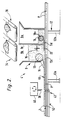
- Figure 1 is a schematic side elevation of a twin hopper tile making machine provided by the invention;
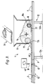
- Figure 2 is a schematic side elevation of a hybrid modification to the hopper arrangement shown in Figure 1;
- Figure 3 is a schematic side elevation of a unitary hopper tile making machine;
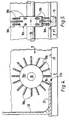
- Figure 4 is an enlarged view of parts shown in Figure 1;
- Figure 5 is a view in the direction of arrow V in Figure 4; and,
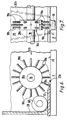
- Figures 6 and 7 are corresponding views to Figures 4 and 5 and illustrate further modifications to the tile making machine.
- In the manufacture of concrete roof tiles by conventional tile processing methods, it has proven difficult if not impossible to ensure the uniform compaction of the layers of mortar throughout the cross-section of the tiles. This is particularly so in the production of tiles with deep reinforcing ribs formed in longitudinal recesses of pallets fed beneath the hopper of a tile making machine.
- The present invention thus comprises a unique tile making machine 4 which enables a novel method of making concrete roof tiles 2 to be effected so that all sections of the tiles produced therein are subjected to uniform or substantially uniform compaction forces resulting in a uniformity of mortar density in the finished product which, when cured, has a uniform strength or substantially so.
- The tile making machine 4, see Figure 1, comprises
twin hoppers 8 and 10 located in series overlying apallet conveyor 12. Theconveyor 12 is of conventional design, is supported on floor mountedcolumns support rails 12c on which pallets P are supported as they pass seriatim beneath thehoppers 8 and 10. - The hopper 8 is also of conventional design and provides support for a
roller 13, aslipper 14 and apack shaft 16. Thehopper 10 is located upstream of the hopper 8 and comprises ashaft 18 located towards afront wall 20 thereof. Theshaft 18 provides support for a primary compaction device comprised of two tinedwheels 18a only one of which is shown in the drawings, the purpose of which tined wheels will be made clear hereinafter. Thefront wall 20 provides support for a secondary compaction device comprised of ablade element 22 the purpose of whichelement 22 will also be made clear hereinafter. - Located above each
hopper 8 and 10 are respectivematerial feed conveyors - Downstream of the hopper 8, the tile making machine is provided with a conventional
tile cutting knife 38 which is mounted for reciprocal vertical and longitudinal movement on aknife carriage 40 illustrated schematically in Figure 1. - The tile making machine also comprises a
pallet spacing conveyor 42 which is arranged beneath theconveyor 12 and adjacent theknife carriage 40 for a purpose also to be made clear hereinafter. - When the machine of Figure 1 is in use in the manufacture of concrete roofing tiles, two batches of mortar are fed by the
conveyors hoppers 8 and 10 respectively. At the same time, pallets P are fed seriatim along thesupport rails 12c of theconveyor 12 so that mortar inhopper 10 is compacted by thetined wheels 18a into upwardly facinglongitudinal recesses 19 of the pallets P, see Figure 5 in which only onesuch recess 19 is shown. - The
recesses 19 enable the formation of the strengthening ribs of a roof tile and, as can be seen in Figure 5, thetined wheels 18a each overlie a respective one of therecesses 19, thewheels 18a each providing support for an array oftines 18b in three equi-spaced seried ranks around the circumference of thewheel 18a. - When the machine is in use and as the pallets P move underneath the
hopper 10 as aforesaid, mortar in thehopper 10 is constrained to flow into therecesses 19 and is partially compacted therein by thetines 18b of thewheels 18a. Subsequently, as the pallets P are carried downstream of thewheels 18a, they pass beneath theblade element 22 which extends downstream from anip portion 22a formed between acircumferential path 18c generated by the rotatingtines 18b of thewheels 18a and an upper surface P1 of the pallets P, see Figure 4. - The
blade element 22 which is between 0.1 and 0.3 the length of a tile pallet P acts in part as a conventional slipper and further compacts the mortar into therecesses 19 to facilitate the manufacture of concrete roof tiles with reinforcing ribs which are fit for purpose. - It has been found that the best results are obtained if the
hopper 10 is only partially filled with mortar as shown in Figure 1. - The pallets P thereafter proceed beneath the hopper 8 whereat the mortar therein is compacted by the
packshaft 16, therollers 13 and theslipper 14 onto the pallets P and the pre-formed reinforcing ribs to form aribbon 46 of mortar on the pallets P in known manner. - The
ribbon 46 is thereafter cut by theknife 38 of the tile cutting arrangement whereupon trailing ends of the pallets P are engaged by driveelements 52 of theconveyor 42 whereby the "green state" tiles 2 on their associated pallets P are conveyed to racking devices prior to transportation to curing chambers. - Whereas the novel method of making a concrete roof tile remains unaltered, the tile making machine may be modified as shown in Figure 2 in which the twin hopper arrangement is replaced by a
hybrid hopper 9 having first andsecond sections hoppers 10 and 8 respectively of Figure 1. Thesections divider plate 9c which supports theblade element 22 at itslower end 9d, see Figure 2. All other features are essentially the same as those of Figure 1 and they have, therefore, been accorded like reference characters. - The tile making machine may also be modified as shown in Figure 3 in which a
unitary hopper 11 comprises support for theroller 13,slipper 14,packshaft 16, tinedwheel 18a and theblade element 22. As with the first modification, all other features are essentially the same and have, therefore, been accorded like references. - In a further modified arrangement provided by the invention, see Figure 7,
guide plates wheels recesses 19 of the pallets P. - In order to obviate any problems with cavitation of mortar in the
hopper 10 of Figure 1 and to ensure recirculation of mortar, ascrew augur 60 may be provided adjacent thewall 20 as shown in Figure 6 which augur 60 feeds mortar to a collection box (not shown) for recirculation to the top of thehopper 10. - Although not forming part of the present invention, it will be obvious that tiles made using the three modified arrangements of Figures 1, 2 and 3 may on the one hand be comprised of different mortars or on the other hand be of the same mortar throughout their thicknesses. In the arrangements of Figures 1 and 2, the mortar delivered by
conveyor 36 to thehopper 10 or thesection 9a of thehopper 9 may, if required, be made of different constituents or have varying amounts of the same constituents in areas to assist the compaction of the reinforcing ribs of tiles made therein. The Figure 3 modification, however, lends itself for use with a single mortar fed by theconveyor 34.
Claims (9)
- A tile making machine comprising a hopper provided with a packshaft, roller and slipper, said packshaft being effective, when the machine is in use and tile pallets are fed seriatim beneath said hopper, to direct mortar onto said pallets as they pass beneath the roller and slipper to form a continuous ribbon of mortar on said pallets, characterised in that the tile making machine also comprises compaction means upstream of said packshaft, roller and slipper, which compaction means comprises a primary compaction device which, when the machine is in use and tile pallets are fed as aforesaid, directs and compacts mortar onto and/or into selected portions only of said pallets said selected portions forming, inter alia, longitudinal strengthening ribs in finished tiles.
- A tile making machine according to Claim 1 further characterised in that said compacting means also comprises a secondary compaction device wherein, when the machine is in use, and after the primary compaction device has directed and compacted mortar onto and/or into the selected portions of the pallets as aforesaid, the secondary compaction device further compacts the mortar in said selected portions only of the pallets as the pallets pass therebeneath to fully compact the mortar of the portions forming the longitudinal strengthening ribs in the finished tile as aforesaid.
- A tile making machine according to either one of Claims 1 and 2 wherein the primary compaction device comprises a multi-tined wheel arranged in use to overlie selected portions only of said pallets as aforesaid.
- A tile making machine according to Claim 3 wherein the multi-tined wheel has an effective width corresponding to the width of the longitudinal strengthening ribs formed by said selected portions only of the pallets.
- A tile making machine according to either one of Claims 3 and 4 wherein the secondary compaction device comprises a thin gauge blade element extending parallel or substantially so to the direction of feed of the pallets fed seriatim beneath said hopper, the blade element comprising a blade portion arranged to lie in or towards a nip portion provided in use of the tile making machine and formed between a circumferential path generated by the tines of the multi-tined wheel and co-planar upper surface portions of said pallets fed therebeneath.
- A tile making machine according to Claim 5 wherein said blade element has an effective length of 0.1 to 0.3 the length of tile pallets used therewith.
- A tile making machine according to any one of the preceding Claims wherein the compaction means is located in said hopper upstream of the packshaft, roller and slipper, as aforesaid.
- A tile making machine according to any one of Claims 1 to 6 wherein the compaction means may be located in a secondary hopper located upstream of said hopper.
- A process for the manufacture of concrete roof tiles using the tile making machine of the preceding claims, said tile making machine being provided with a hopper supporting a packshaft, a roller and a slipper all of known configuration, said process comprising the steps of:a) supplying mortar to a compacting means located upstream of said packshaft, roller and slipper;b) causing tile pallets to be fed seriatim beneath said compacting means whereat, when the process is being effected, mortar is directed and compacted onto and/or into selected portions only of said pallets, said selected portions forming longitudinal strengthening ribs in the finished tile;c) feeding said pallets with said selected portions covered and/or filled with mortar seriatim beneath said packshaft, roller and slipper whereby, as said process is effected, further mortar is directed onto said pallets and the mortar already compacted on and/or in said selected portions of said pallets to form a cohesive continuous ribbon of mortar on said pallets;d) cutting said ribbon of mortar to form discrete "green state" tiles on individual pellets; and,e) causing said "green state" tiles to be cured.
Applications Claiming Priority (3)
| Application Number | Priority Date | Filing Date | Title |
|---|---|---|---|
| GB9308887 | 1993-04-29 | ||
| GB9308887A GB2277707B (en) | 1993-04-29 | 1993-04-29 | Improvements in a roof tile making machine |
| PCT/EP1994/001443 WO1994025235A1 (en) | 1993-04-29 | 1994-04-28 | Improvements in a roof tile making machine |
Publications (2)
| Publication Number | Publication Date |
|---|---|
| EP0697943A1 EP0697943A1 (en) | 1996-02-28 |
| EP0697943B1 true EP0697943B1 (en) | 1996-12-27 |
Family
ID=10734693
Family Applications (1)
| Application Number | Title | Priority Date | Filing Date |
|---|---|---|---|
| EP94916202A Expired - Lifetime EP0697943B1 (en) | 1993-04-29 | 1994-04-28 | Improvements in a roof tile making machine |
Country Status (21)
| Country | Link |
|---|---|
| US (1) | US5820802A (en) |
| EP (1) | EP0697943B1 (en) |
| JP (1) | JPH08509433A (en) |
| KR (1) | KR960701732A (en) |
| CN (1) | CN1042409C (en) |
| AT (1) | ATE146720T1 (en) |
| AU (1) | AU677068B2 (en) |
| BG (1) | BG61685B1 (en) |
| CA (1) | CA2161131A1 (en) |
| CZ (1) | CZ283695A3 (en) |
| DE (1) | DE69401274T2 (en) |
| DK (1) | DK0697943T3 (en) |
| ES (1) | ES2098145T3 (en) |
| FI (1) | FI955022A7 (en) |
| GB (1) | GB2277707B (en) |
| HU (1) | HUT71924A (en) |
| NO (1) | NO301970B1 (en) |
| NZ (1) | NZ266455A (en) |
| PL (1) | PL173793B1 (en) |
| SK (1) | SK132095A3 (en) |
| WO (1) | WO1994025235A1 (en) |
Families Citing this family (12)
| Publication number | Priority date | Publication date | Assignee | Title |
|---|---|---|---|---|
| ITRE20010072A1 (en) * | 2001-07-05 | 2003-01-05 | Sacmi | METHOD FOR LOADING THE CERAMIC MOLDS OF FORMING THE TILES, IMPLANT FOR ITS IMPLEMENTATION, AND TILES OBTAINED WITH DET |
| ITRE20030004A1 (en) * | 2003-01-20 | 2004-07-21 | Sacmi | METHOD AND PLANT FOR THE FORMING OF SLABS OR CERAMIC TILES. |
| ES2272117B1 (en) * | 2004-03-10 | 2008-02-01 | Juan Jose Martinez De Gracia | MACHINE FOR THE MANUFACTURE OF BRICKS, TILES AND SIMILAR. |
| ITRE20040150A1 (en) * | 2004-12-10 | 2005-03-10 | Sacmi | IMPROVED PLANT FOR FORMING CERAMIC SHEETS OR TILES |
| DE102005038338B4 (en) * | 2005-08-13 | 2009-01-08 | Christian Prilhofer | Pallet circulation system with continuous pallet transport for the production of concrete parts |
| US20100013117A1 (en) | 2006-09-01 | 2010-01-21 | Bhushan Kumar Oberoi | Method for the manufacture of a building product |
| ITTV20070054A1 (en) * | 2007-03-28 | 2008-09-29 | Luca Toncelli | PROCEDURE FOR THE MANUFACTURE OF CERAMIC MATERIAL SLABS |
| ITTV20070126A1 (en) | 2007-07-16 | 2009-01-17 | Luca Toncelli | PROCEDURE AND EQUIPMENT FOR THE MANUFACTURE OF EFFET-VENATO SLABS |
| IT1393456B1 (en) * | 2009-03-10 | 2012-04-20 | Toncelli | EQUIPMENT AND METHOD FOR THE MANUFACTURE OF SHEETS WITH VENATO EFFECT |
| TR201106066A2 (en) | 2011-06-21 | 2012-01-23 | Ti̇cem İleri̇ Yapi Teknoloji̇leri̇ Sanayi̇ Ti̇caret Danişmanlik Li̇mi̇ted Şi̇rketi̇ | Cement based panel obtaining system and method which is thin and has high production speed, strength and durability. |
| ITRE20110079A1 (en) * | 2011-10-07 | 2013-04-08 | Sacmi | DEVICE FOR THE COMPACTION OF MATERIAL POWDER |
| CN108789802A (en) * | 2017-05-03 | 2018-11-13 | 湖南晨熙绿色建筑产业有限公司 | A kind of uniform blanking machine in heat preservation dismounting-free formwork production process |
Family Cites Families (17)
| Publication number | Priority date | Publication date | Assignee | Title |
|---|---|---|---|---|
| DE219443C (en) * | ||||
| FR934460A (en) * | 1947-08-05 | 1948-05-24 | Tile and machine used in its manufacture | |
| US3303245A (en) * | 1963-09-09 | 1967-02-07 | Terraz Epoxy Inc | Process for production of tile products |
| US3477108A (en) * | 1966-05-11 | 1969-11-11 | John F Stokes | House prefabricating machine |
| BE790282A (en) * | 1971-10-25 | 1973-02-15 | Redland Tiles Ltd | PERFECTED APPARATUS FOR THE MANUFACTURING OF TILES |
| DE2242245C3 (en) * | 1972-08-28 | 1975-10-23 | Max Roth Kg, 7560 Gaggenau | Slip paver |
| US4068990A (en) * | 1976-03-26 | 1978-01-17 | Arvids Kalns | Concrete slab forming machine |
| AT368436B (en) * | 1980-02-26 | 1982-10-11 | Bramac Dachsteinwerk Gmbh | DEVICE FOR PRODUCING PROFILED ROOF TILES FROM CONCRETE OR THE LIKE. |
| CA1198882A (en) * | 1982-04-08 | 1986-01-07 | Marley Tile A.G. | Roof tiles |
| DE3418134A1 (en) * | 1984-05-16 | 1985-11-21 | Ing. Kurt Schade Formen- und Werkzeugbau, 2878 Wildeshausen | MOLDING BOX OF A MACHINE FOR THE CONSTRUCTION OF CONCRETE ROOF TILES, IN PARTICULAR ORGANIC TILES |
| US5223200A (en) * | 1985-06-26 | 1993-06-29 | Braas Gmbh | Method for producing concrete roof tiles |
| GB2198073B (en) * | 1986-11-28 | 1990-01-24 | Redland Roof Tiles Ltd | Improvements in cutting mechanisms |
| GB2198072B (en) * | 1986-12-03 | 1990-07-11 | Nii Str Arkhitektury Gosstroya | Apparatus for molding articles from fibrous concrete |
| AU608760B2 (en) * | 1987-06-23 | 1991-04-18 | Braas & Co. G.M.B.H. | Process and device for manufacturing roof covering board with transverse integrally formed flange |
| US5075985A (en) * | 1990-08-06 | 1991-12-31 | Mensch Donald L | Offal scraper |
| GB9022277D0 (en) * | 1990-10-13 | 1990-11-28 | Redland Eng Ltd | Improvements in or relating to the manufacture of roof tiles |
| US5406766A (en) * | 1993-07-29 | 1995-04-18 | Monier Roof Tile Inc. | Multi-color concrete tiles and method and apparatus for making same |
-
1993
- 1993-04-29 GB GB9308887A patent/GB2277707B/en not_active Expired - Fee Related
-
1994
- 1994-04-28 SK SK1320-95A patent/SK132095A3/en unknown
- 1994-04-28 CN CN94191920A patent/CN1042409C/en not_active Expired - Fee Related
- 1994-04-28 AU AU67961/94A patent/AU677068B2/en not_active Ceased
- 1994-04-28 WO PCT/EP1994/001443 patent/WO1994025235A1/en not_active Ceased
- 1994-04-28 KR KR1019950704722A patent/KR960701732A/en not_active Ceased
- 1994-04-28 US US08/537,825 patent/US5820802A/en not_active Expired - Fee Related
- 1994-04-28 ES ES94916202T patent/ES2098145T3/en not_active Expired - Lifetime
- 1994-04-28 HU HU9503079A patent/HUT71924A/en unknown
- 1994-04-28 CZ CZ952836A patent/CZ283695A3/en unknown
- 1994-04-28 AT AT94916202T patent/ATE146720T1/en not_active IP Right Cessation
- 1994-04-28 JP JP6523916A patent/JPH08509433A/en active Pending
- 1994-04-28 EP EP94916202A patent/EP0697943B1/en not_active Expired - Lifetime
- 1994-04-28 NZ NZ266455A patent/NZ266455A/en unknown
- 1994-04-28 CA CA002161131A patent/CA2161131A1/en not_active Abandoned
- 1994-04-28 DE DE69401274T patent/DE69401274T2/en not_active Expired - Fee Related
- 1994-04-28 PL PL94311237A patent/PL173793B1/en unknown
- 1994-04-28 DK DK94916202.8T patent/DK0697943T3/en active
-
1995
- 1995-10-20 FI FI955022A patent/FI955022A7/en not_active Application Discontinuation
- 1995-10-23 BG BG100080A patent/BG61685B1/en unknown
- 1995-10-27 NO NO954326A patent/NO301970B1/en unknown
Also Published As
| Publication number | Publication date |
|---|---|
| GB2277707B (en) | 1996-07-03 |
| AU677068B2 (en) | 1997-04-10 |
| ATE146720T1 (en) | 1997-01-15 |
| CN1042409C (en) | 1999-03-10 |
| SK132095A3 (en) | 1996-02-07 |
| CZ283695A3 (en) | 1996-02-14 |
| NO954326D0 (en) | 1995-10-27 |
| NO301970B1 (en) | 1998-01-05 |
| NO954326L (en) | 1995-10-27 |
| DK0697943T3 (en) | 1997-06-16 |
| CA2161131A1 (en) | 1994-11-10 |
| KR960701732A (en) | 1996-03-28 |
| DE69401274T2 (en) | 1997-07-17 |
| DE69401274D1 (en) | 1997-02-06 |
| CN1121697A (en) | 1996-05-01 |
| US5820802A (en) | 1998-10-13 |
| AU6796194A (en) | 1994-11-21 |
| PL173793B1 (en) | 1998-05-29 |
| BG100080A (en) | 1996-06-28 |
| BG61685B1 (en) | 1998-03-31 |
| GB2277707A (en) | 1994-11-09 |
| FI955022A0 (en) | 1995-10-20 |
| EP0697943A1 (en) | 1996-02-28 |
| ES2098145T3 (en) | 1997-04-16 |
| HU9503079D0 (en) | 1995-12-28 |
| JPH08509433A (en) | 1996-10-08 |
| WO1994025235A1 (en) | 1994-11-10 |
| GB9308887D0 (en) | 1993-06-16 |
| FI955022A7 (en) | 1995-10-20 |
| NZ266455A (en) | 1997-10-24 |
| HUT71924A (en) | 1996-02-28 |
| PL311237A1 (en) | 1996-02-05 |
Similar Documents
| Publication | Publication Date | Title |
|---|---|---|
| US5820802A (en) | Tile making machine and method | |
| FI85451C (en) | Process and plant for the production of disc product substance | |
| CA1109222A (en) | Method with combined vibration and pressure action in an airless environment for the formation of resin- bonded grit slabs and apparatus for implementing said method | |
| US3982358A (en) | Laminated resinoid wheels, method for continuously producing same and apparatus for use in the method | |
| EP3990238B1 (en) | Plant and method for the production of slabs made of composite stone material from a mix | |
| US5569419A (en) | Continuous flow process of mold-making or die-making using a reusable mixture substance to make selected finished products | |
| CA1046246A (en) | Apparatus for manufacturing plaster sheets | |
| US1353510A (en) | Art of manufacturing slabs or the like of cement or like material | |
| US3850558A (en) | Installation for manufacturing resin based concrete | |
| US1367227A (en) | Machine for manufacturing slabs or the like of cement or like material | |
| AU608760B2 (en) | Process and device for manufacturing roof covering board with transverse integrally formed flange | |
| US4908217A (en) | Apparatus for making tiles or slabs | |
| USRE30759E (en) | Method and apparatus for producing and transporting single and multilayer chipboards | |
| US20040013864A1 (en) | Highly flexible thin agglomerate sheets or panels and process and plant for production of the same | |
| EP0190565B1 (en) | Hollow block and device for making same | |
| US3067456A (en) | Apparatus for producing pressed wood-particle panels | |
| GB2248578A (en) | Casting stratified concrete roofing tiles | |
| US3980453A (en) | Laminated resinoid wheels, method for continuously producing same and apparatus for use in the method | |
| US3964849A (en) | Mold apparatus for continuously producing laminated resinoid material | |
| US3231438A (en) | Method of and apparatus for producing laminated elements | |
| EP0203974A1 (en) | Tile making apparatus and method | |
| US1819199A (en) | Method of making building materials | |
| KR20200088011A (en) | Manufacturing Method and Apparatus of Concrete Tile for Interior and Exterior Material of Building | |
| US1868139A (en) | Apparatus for making molded products | |
| WO1997002122A1 (en) | Improvements in the manufacture of roof tiles |
Legal Events
| Date | Code | Title | Description |
|---|---|---|---|
| PUAI | Public reference made under article 153(3) epc to a published international application that has entered the european phase |
Free format text: ORIGINAL CODE: 0009012 |
|
| 17P | Request for examination filed |
Effective date: 19951113 |
|
| AK | Designated contracting states |
Kind code of ref document: A1 Designated state(s): AT BE CH DE DK ES FR GB IE IT LI LU NL PT SE |
|
| GRAG | Despatch of communication of intention to grant |
Free format text: ORIGINAL CODE: EPIDOS AGRA |
|
| 17Q | First examination report despatched |
Effective date: 19960425 |
|
| GRAH | Despatch of communication of intention to grant a patent |
Free format text: ORIGINAL CODE: EPIDOS IGRA |
|
| GRAH | Despatch of communication of intention to grant a patent |
Free format text: ORIGINAL CODE: EPIDOS IGRA |
|
| GRAA | (expected) grant |
Free format text: ORIGINAL CODE: 0009210 |
|
| AK | Designated contracting states |
Kind code of ref document: B1 Designated state(s): AT BE CH DE DK ES FR GB IE IT LI LU NL PT SE |
|
| REF | Corresponds to: |
Ref document number: 146720 Country of ref document: AT Date of ref document: 19970115 Kind code of ref document: T |
|
| REF | Corresponds to: |
Ref document number: 69401274 Country of ref document: DE Date of ref document: 19970206 |
|
| REG | Reference to a national code |
Ref country code: IE Ref legal event code: FG4D Free format text: 71299 |
|
| PGFP | Annual fee paid to national office [announced via postgrant information from national office to epo] |
Ref country code: DK Payment date: 19970318 Year of fee payment: 4 |
|
| ITF | It: translation for a ep patent filed | ||
| PGFP | Annual fee paid to national office [announced via postgrant information from national office to epo] |
Ref country code: SE Payment date: 19970407 Year of fee payment: 4 |
|
| PGFP | Annual fee paid to national office [announced via postgrant information from national office to epo] |
Ref country code: ES Payment date: 19970415 Year of fee payment: 4 |
|
| REG | Reference to a national code |
Ref country code: CH Ref legal event code: NV Representative=s name: FELBER & PARTNER AG PATENTANWAELTE |
|
| PGFP | Annual fee paid to national office [announced via postgrant information from national office to epo] |
Ref country code: PT Payment date: 19970416 Year of fee payment: 4 |
|
| REG | Reference to a national code |
Ref country code: ES Ref legal event code: FG2A Ref document number: 2098145 Country of ref document: ES Kind code of ref document: T3 |
|
| PGFP | Annual fee paid to national office [announced via postgrant information from national office to epo] |
Ref country code: CH Payment date: 19970421 Year of fee payment: 4 |
|
| ET | Fr: translation filed | ||
| PG25 | Lapsed in a contracting state [announced via postgrant information from national office to epo] |
Ref country code: LU Free format text: LAPSE BECAUSE OF NON-PAYMENT OF DUE FEES Effective date: 19970430 |
|
| REG | Reference to a national code |
Ref country code: DK Ref legal event code: T3 |
|
| REG | Reference to a national code |
Ref country code: PT Ref legal event code: SC4A Free format text: AVAILABILITY OF NATIONAL TRANSLATION Effective date: 19970312 |
|
| PLBE | No opposition filed within time limit |
Free format text: ORIGINAL CODE: 0009261 |
|
| STAA | Information on the status of an ep patent application or granted ep patent |
Free format text: STATUS: NO OPPOSITION FILED WITHIN TIME LIMIT |
|
| 26N | No opposition filed | ||
| PG25 | Lapsed in a contracting state [announced via postgrant information from national office to epo] |
Ref country code: SE Free format text: LAPSE BECAUSE OF NON-PAYMENT OF DUE FEES Effective date: 19980429 Ref country code: ES Free format text: THE PATENT HAS BEEN ANNULLED BY A DECISION OF A NATIONAL AUTHORITY Effective date: 19980429 |
|
| PG25 | Lapsed in a contracting state [announced via postgrant information from national office to epo] |
Ref country code: LI Free format text: LAPSE BECAUSE OF NON-PAYMENT OF DUE FEES Effective date: 19980430 Ref country code: DK Free format text: LAPSE BECAUSE OF NON-PAYMENT OF DUE FEES Effective date: 19980430 Ref country code: CH Free format text: LAPSE BECAUSE OF NON-PAYMENT OF DUE FEES Effective date: 19980430 |
|
| PG25 | Lapsed in a contracting state [announced via postgrant information from national office to epo] |
Ref country code: PT Free format text: LAPSE BECAUSE OF NON-PAYMENT OF DUE FEES Effective date: 19981031 |
|
| REG | Reference to a national code |
Ref country code: CH Ref legal event code: PL |
|
| EUG | Se: european patent has lapsed |
Ref document number: 94916202.8 |
|
| REG | Reference to a national code |
Ref country code: PT Ref legal event code: MM4A Free format text: LAPSE DUE TO NON-PAYMENT OF FEES Effective date: 19981031 |
|
| PGFP | Annual fee paid to national office [announced via postgrant information from national office to epo] |
Ref country code: IE Payment date: 19990407 Year of fee payment: 6 |
|
| REG | Reference to a national code |
Ref country code: DK Ref legal event code: EBP |
|
| PGFP | Annual fee paid to national office [announced via postgrant information from national office to epo] |
Ref country code: BE Payment date: 20000418 Year of fee payment: 7 |
|
| PG25 | Lapsed in a contracting state [announced via postgrant information from national office to epo] |
Ref country code: IE Free format text: LAPSE BECAUSE OF NON-PAYMENT OF DUE FEES Effective date: 20000428 |
|
| REG | Reference to a national code |
Ref country code: ES Ref legal event code: FD2A Effective date: 20001204 |
|
| REG | Reference to a national code |
Ref country code: IE Ref legal event code: MM4A |
|
| PG25 | Lapsed in a contracting state [announced via postgrant information from national office to epo] |
Ref country code: BE Free format text: LAPSE BECAUSE OF NON-PAYMENT OF DUE FEES Effective date: 20010430 |
|
| BERE | Be: lapsed |
Owner name: REDLAND TECHNOLOGIES LTD Effective date: 20010430 |
|
| REG | Reference to a national code |
Ref country code: GB Ref legal event code: IF02 |
|
| REG | Reference to a national code |
Ref country code: GB Ref legal event code: 732E |
|
| PGFP | Annual fee paid to national office [announced via postgrant information from national office to epo] |
Ref country code: DE Payment date: 20080423 Year of fee payment: 15 |
|
| PGFP | Annual fee paid to national office [announced via postgrant information from national office to epo] |
Ref country code: AT Payment date: 20080423 Year of fee payment: 15 |
|
| PGFP | Annual fee paid to national office [announced via postgrant information from national office to epo] |
Ref country code: IT Payment date: 20080421 Year of fee payment: 15 |
|
| PGFP | Annual fee paid to national office [announced via postgrant information from national office to epo] |
Ref country code: NL Payment date: 20080429 Year of fee payment: 15 |
|
| PGFP | Annual fee paid to national office [announced via postgrant information from national office to epo] |
Ref country code: GB Payment date: 20080422 Year of fee payment: 15 |
|
| GBPC | Gb: european patent ceased through non-payment of renewal fee |
Effective date: 20090428 |
|
| NLV4 | Nl: lapsed or anulled due to non-payment of the annual fee |
Effective date: 20091101 |
|
| REG | Reference to a national code |
Ref country code: FR Ref legal event code: ST Effective date: 20091231 |
|
| PG25 | Lapsed in a contracting state [announced via postgrant information from national office to epo] |
Ref country code: DE Free format text: LAPSE BECAUSE OF NON-PAYMENT OF DUE FEES Effective date: 20091103 Ref country code: AT Free format text: LAPSE BECAUSE OF NON-PAYMENT OF DUE FEES Effective date: 20090428 |
|
| PG25 | Lapsed in a contracting state [announced via postgrant information from national office to epo] |
Ref country code: NL Free format text: LAPSE BECAUSE OF NON-PAYMENT OF DUE FEES Effective date: 20091101 |
|
| PG25 | Lapsed in a contracting state [announced via postgrant information from national office to epo] |
Ref country code: GB Free format text: LAPSE BECAUSE OF NON-PAYMENT OF DUE FEES Effective date: 20090428 Ref country code: FR Free format text: LAPSE BECAUSE OF NON-PAYMENT OF DUE FEES Effective date: 20091222 |
|
| PGFP | Annual fee paid to national office [announced via postgrant information from national office to epo] |
Ref country code: FR Payment date: 20080422 Year of fee payment: 15 |
|
| PG25 | Lapsed in a contracting state [announced via postgrant information from national office to epo] |
Ref country code: IT Free format text: LAPSE BECAUSE OF NON-PAYMENT OF DUE FEES Effective date: 20090428 |