EP0696893B1 - Low temperature display merchandiser - Google Patents
Low temperature display merchandiser Download PDFInfo
- Publication number
- EP0696893B1 EP0696893B1 EP94916586A EP94916586A EP0696893B1 EP 0696893 B1 EP0696893 B1 EP 0696893B1 EP 94916586 A EP94916586 A EP 94916586A EP 94916586 A EP94916586 A EP 94916586A EP 0696893 B1 EP0696893 B1 EP 0696893B1
- Authority
- EP
- European Patent Office
- Prior art keywords
- air
- primary
- merchandiser
- shelf
- curtain
- Prior art date
- Legal status (The legal status is an assumption and is not a legal conclusion. Google has not performed a legal analysis and makes no representation as to the accuracy of the status listed.)
- Expired - Lifetime
Links
- 230000002441 reversible effect Effects 0.000 claims abstract description 8
- 238000010257 thawing Methods 0.000 claims abstract description 6
- 239000003570 air Substances 0.000 claims description 217
- 238000005057 refrigeration Methods 0.000 claims description 25
- 239000003507 refrigerant Substances 0.000 claims description 11
- 238000004891 communication Methods 0.000 claims description 6
- 238000007789 sealing Methods 0.000 claims description 6
- 239000012080 ambient air Substances 0.000 claims description 4
- 238000007599 discharging Methods 0.000 claims description 2
- 230000005465 channeling Effects 0.000 claims 3
- 235000013611 frozen food Nutrition 0.000 abstract description 14
- 238000001816 cooling Methods 0.000 abstract description 9
- 235000013305 food Nutrition 0.000 abstract description 9
- 235000015243 ice cream Nutrition 0.000 abstract description 6
- 230000015572 biosynthetic process Effects 0.000 abstract description 4
- 241000264877 Hippospongia communis Species 0.000 description 12
- 239000011521 glass Substances 0.000 description 6
- 230000002829 reductive effect Effects 0.000 description 4
- 238000005192 partition Methods 0.000 description 3
- 235000019687 Lamb Nutrition 0.000 description 2
- 230000008859 change Effects 0.000 description 2
- 238000005265 energy consumption Methods 0.000 description 2
- 239000006260 foam Substances 0.000 description 2
- 206010022000 influenza Diseases 0.000 description 2
- 230000009467 reduction Effects 0.000 description 2
- 230000002411 adverse Effects 0.000 description 1
- 230000004888 barrier function Effects 0.000 description 1
- 230000000903 blocking effect Effects 0.000 description 1
- 230000005494 condensation Effects 0.000 description 1
- 238000009833 condensation Methods 0.000 description 1
- 230000001419 dependent effect Effects 0.000 description 1
- 230000000694 effects Effects 0.000 description 1
- 238000009432 framing Methods 0.000 description 1
- 239000007788 liquid Substances 0.000 description 1
- 238000012423 maintenance Methods 0.000 description 1
- 239000000463 material Substances 0.000 description 1
- 239000002184 metal Substances 0.000 description 1
- 230000005012 migration Effects 0.000 description 1
- 238000013508 migration Methods 0.000 description 1
- 238000012986 modification Methods 0.000 description 1
- 230000004048 modification Effects 0.000 description 1
- 230000036961 partial effect Effects 0.000 description 1
- 230000001681 protective effect Effects 0.000 description 1
- 230000003134 recirculating effect Effects 0.000 description 1
Images



Classifications
-
- F—MECHANICAL ENGINEERING; LIGHTING; HEATING; WEAPONS; BLASTING
- F25—REFRIGERATION OR COOLING; COMBINED HEATING AND REFRIGERATION SYSTEMS; HEAT PUMP SYSTEMS; MANUFACTURE OR STORAGE OF ICE; LIQUEFACTION SOLIDIFICATION OF GASES
- F25D—REFRIGERATORS; COLD ROOMS; ICE-BOXES; COOLING OR FREEZING APPARATUS NOT OTHERWISE PROVIDED FOR
- F25D21/00—Defrosting; Preventing frosting; Removing condensed or defrost water
- F25D21/06—Removing frost
- F25D21/12—Removing frost by hot-fluid circulating system separate from the refrigerant system
- F25D21/125—Removing frost by hot-fluid circulating system separate from the refrigerant system the hot fluid being ambient air
-
- A—HUMAN NECESSITIES
- A47—FURNITURE; DOMESTIC ARTICLES OR APPLIANCES; COFFEE MILLS; SPICE MILLS; SUCTION CLEANERS IN GENERAL
- A47F—SPECIAL FURNITURE, FITTINGS, OR ACCESSORIES FOR SHOPS, STOREHOUSES, BARS, RESTAURANTS OR THE LIKE; PAYING COUNTERS
- A47F3/00—Show cases or show cabinets
- A47F3/04—Show cases or show cabinets air-conditioned, refrigerated
- A47F3/0439—Cases or cabinets of the open type
- A47F3/0443—Cases or cabinets of the open type with forced air circulation
- A47F3/0447—Cases or cabinets of the open type with forced air circulation with air curtains
-
- A—HUMAN NECESSITIES
- A47—FURNITURE; DOMESTIC ARTICLES OR APPLIANCES; COFFEE MILLS; SPICE MILLS; SUCTION CLEANERS IN GENERAL
- A47F—SPECIAL FURNITURE, FITTINGS, OR ACCESSORIES FOR SHOPS, STOREHOUSES, BARS, RESTAURANTS OR THE LIKE; PAYING COUNTERS
- A47F3/00—Show cases or show cabinets
- A47F3/04—Show cases or show cabinets air-conditioned, refrigerated
- A47F3/0439—Cases or cabinets of the open type
- A47F3/0443—Cases or cabinets of the open type with forced air circulation
- A47F2003/046—Cases or cabinets of the open type with forced air circulation with shelves having air ducts
Definitions
- This invention relates generally to the commercial refrigeration art, and more particularly to improvements in product merchandisers especially designed for the low temperature refrigeration of frozen food products.
- All frozen food merchandisers are designed with 10 the primary objective of maintaining product temperatures in the display area at about 0°F for frozen food and about -5°F to -10°F for ice cream, which in the past has required evaporator coil temperatures in the range of -20°F down to -35°F.
- evaporator coil temperatures in the range of -20°F down to -35°F.
- ice 15 buildup on the evaporator coils is accelerated, and thus the frequency' and/or duration time of coil defrosts has been higher with the result that defrost heat usually produces increases in product zone temperatures.
- the inefficiency of prior art open front frozen food display cases has resulted in high energy consumption requirements.
- the large energy costs coupled with the inherent problems of maintaining proper product temperatures for good quality shelf life resulted in a marketing trend to closed, glass front reach-in merchandisers.
- a refrigerated merchandiser according to the preamble of the independent claim is known from US-A-3 063 256.
- the invention is embodied in a low temperature food merchandiser having a cabinet with an open front product area, a primary cold air system for maintaining substantially constant low target temperatures of at least (0°F) in the product area including the formation of plural primary low temperature air curtains across the open front, a secondary air system protecting the primary air curtains, and the primary system also including primary evaporator cooling means constructed and arranged to operate at elevated coil temperatures in the range of about -22.2°C to -24.4°C (-8°F to -12°F) to maintain the -17.8°C to -23.3°C (0°F to -10°F) product area temperatures and including reverse air cycle defrost means for periodically defrosting the primary cooling means.
- a principaly object of the present invention is to provide an open front, multideck frozen product merchandiser having a wide range of display shelf flexibility in adjustment or removal.
- Another object of the present invention is to provide a low temperature open front food merchandiser in which optimum product temperatures are maintained with elevated coil operating temperatures and minimum icing conditions.
- Another object is to provide an open front merchandiser having a primary low temperature air system having a plurality of discrete shelf display zones protected by the discharge of separate air curtains.
- Another object is to provide a multideck, open front, low temperature merchandiser that is efficient in operation and affords substantial energy consumption savings in the order of 30% to 40% relative to comparable sized prior merchandisers.
- Another object is to provide a frozen product merchandiser affording improvements in product display with a variable capacity lower well, individual shelf adjustment and adjustable light modulation.
- Another object is to provide a merchandiser with a highly efficient low temperature refrigeration system and primary air distribution network.
- the present invention constitutes improvements in open front, low temperature, multideck product display merchandisers M having an outer cabinet C with a vertical, open front, product display zone Z cooled to its predetermined low temperature condition by a primary air system P and which is further protected by a secondary air system S and a tertiary air system T.
- low temperature has reference to frozen food product temperatures of -17.8°C (o°F) and ice cream product temperatures of at least 20.6°c (-5°F), except as may otherwise be specifically described.
- the cabinet C of the merchandiser M of the present invention includes an insulated outer cabinet having a base 11, a low front wall 12, a high rear wall 13, a top wall 14 extending forwardly from the rear wall 13 and end walls 15 including forwardly extending three-pane thermal glass panels 16 with front' trim strips 16a.
- the front of the frozen food merchandiser N is open between the top of the front wall 12 and the front of the top wall 14 for direct accessibility to the interior product zone Z of the merchandiser.
- an intermediate cabinet liner Positioned within the outer cabinet and extending longitudinally between the end walls 15 is an intermediate cabinet liner which includes a bottom wall or panel 17 in spaced relation with the base 11 to provide a bottom outer air flue or duct 18, a front or panel wall 19 spaced from the front wall 12 to provide a front flue or return duct 20 in communication with the bottom flue 18 as part of the secondary system 5, an insulated rear duct or wall 21 spaced from the back or rear wall 13 to provide a rear duct or flue 22 also in communication with the bottom flue 18, and an insulated top wall or panel 23 spaced below the outer top wall 14 and defining an air distribution chamber 24 of the secondary air system S.
- the forward end of the top or upper wall 23 has a projecting depending front member 25 extending away from the top wall 14, and the top wall 14 of the outer cabinet also has a short depending vertical front wall 27 extending downwardly therefrom in forward spaced relation with the front wall member 25 to form a front discharge area or chamber 28 at the front of the chamber 24 of the secondary system S.
- a relatively wide horizontal section of honeycomb material 29 is constructed and arranged to bridge across or span the front walls 25 and 27 and form the vertical air discharge means through which non-refrigerated air of the secondary system S is discharged, as will be described more fully.
- the wall 23 slopes upwardly from the rear panel 21, and the rearward portion of the chamber 24 houses a fan 30 or other air circulating means.
- the chamber 24 is divided in the usual way by a partition 31 extending linearly the length of the cabinet between the rear wall 13 and the top wall 23 and having spaced openings 32 in which the fan blades 33 of plural fans 30 are mounted for efficiently moving air through the entire outer flue network of the secondary system S and in a vertical air curtain SC across the open front of the merchandiser to the return duct 20.
- the chamber 24 is defined by the forwardly. narrowing or converging walls 14 and 23, and that another air control partition or baffle 34 is positioned immediately adjacent to the discharge honeycomb or air straightening means 29 so that the discharge area or chamber 28 is defined by a tapering air delivery throat for pressurising and evening air flow distribution longitudinally and laterally of the honeycomb 29.
- the return duct or flue 20, bottom and rear flues 18 and 22, upper chamber 24 and discharge area and member 28, 28a, 29 form an air circulatory system for continuously recirculating non-refrigerated air.
- This secondary system S does not directly cool food products in the display area Z, but forms a protective air wall both during normal refrigeration and defrost cycles of the primary system P.
- the fans 30 create a negative pressure through the rear, bottom and front flues to draw air curtain air into the front flue 20 and to continuously recirculate the air of the secondary system S in maintaining the secondary air curtain SC discharged downwardly across the merchandiser M.
- the merchandiser M also includes an innermost cabinet defining the display area Z in which frozen food products are placed for refrigerated merchandising.
- the inner cabinet also extends linearly the longitudinal extent between the end walls 15, 16 of the outer cabinet, and includes an insulated bottom panel or wall 35 spaced above the bottom wall 17 of the intermediate cabinet to form a lower or front refrigeration chamber 36.
- An insulated front panel 37 is spaced from the front wall 19 of the intermediate cabinet and provides a cold air return flue or duct 38 of the primary air system P therebetween, the panel 37 having an angularly-positioned perforated plate 39 secured to the front wall 19 and forming the return inlet for the front flue 38.
- the inner cabinet also includes a lower rear panel 41 spaced forwardly from the rear wall 21 of the intermediate cabinet and defining a main rear refrigeration chamber 42 therebetween.
- the return flue 38 is in communication with the front refrigeration chamber 36, which houses a front evaporator coil section 43 extending the longitudinal length of the merchandiser M.
- the refrigeration chamber 38 is divided by an angular partition 44 having longitudinally spaced openings 45 for fan blades 46 of fans 47 or like air circulating means.
- the main rear chamber 42 is in open air flow communication with the front refrigeration chamber 36 and coil 43 through the fan openings 45, and the rear refrigeration chamber 42 houses the full length main evaporator coil section 48 through which primary air is moved by the fans 47.
- the coil sections 43 and 48 are part of a commercial closed refrigeration system (not shown) that does not form a part of the invention except as to the refrigerant distribution and coil defrost cycles to be described.
- the front and rear chambers 36 and 42 form an L-shaped main refrigeration chamber positioned at the bottom and rear of the cabinet and having inlet and outlet ends as part of the primary refrigerated air system P with the normal air flow circulation being downwardly in the front flue 38 and across the front coil section 43 and upwardly through the rear coil section 48.
- the refrigeration system liquid line (not shown) is brought into the base of the merchandiser cabinet in a conventional way and connects to a conventional thermostatic expansion valve 50 or the like.
- the expansion valve 50 is piped by six parallel coil runs or circuits 51 of substantially equal length extending across one end of the chambers 36 and 42 and connecting with the upper coil inlet tubes 52 to each of six vertical circuits 53 through the rear main coil 48.
- Refrigerant flow is first distributed to the upper coil tubing of the rear. coil 48 from the expansion valve 50, which thus will be the coldest zone of the main system and which is also the area of primary air discharge upwardly and outwardly of the main coil section 48 for distribution to cool the product zone Z.
- Refrigerant flow is downwardly in the rear coil 48 in reverse flow to the direction of primary air movement through the coil during the refrigeration cycle.
- the six separate vertical coil circuits 53 are connected in pairs at the bottom of the rear coil to three horizontal refrigerant circuits 54 which connect to three corresponding coil circuits 55 of the front coil 43, which in turn are connected to a suction line take-off in a usual manner for returning expanded vaporized refrigerant to the refrigeration system compressors (not shown).
- the conduit size of the six distribution circuits 51 and rear coil tubes 53 is relatively smaller than the conduit size of the three connection circuits 54 and front coil tubes 55 to eliminate pressure drop in the evaporator coils except as typically controlled through the entire circuitry from the expansion valve 50.
- the six delivery circuits 51 and rear coil tubing 53 may be sized at 15.9mm '5/8 inch', and the three connection circuits 54 and front coil tubing 55 may be sized at 19mm ' 3/4 inch'.
- the refrigeration cooling means for the primary air system P produces the coldest coil temperatures at the point of primary air discharge from the rear coil section 48, and slightly warmer coil temperatures will prevail at the return air lead-in to the front coil 43.
- the temperature of the primary air exiting the rear coil 48 must be in the range of -18.9°c(-2°F), to -20.6°c(-5°F), and optimally at about -19.4°c(-3°F), which is produced by rear coil temperatures in the range of -20.6°c(-5°F), to -22.2°c(-8°F), in the present merchandiser.
- the rear coil operates at about -24.4°c(-12°F), to -26.1°c(-15°F), to produce exit air temperatures of about -23.3°c(-10°F), to -24.4°c(-12°F), to maintain the product area target temperature of at least -20.6°c(-5°F), which contrasts with prior ice cream merchandisers requiring about -34.4°c (-30°F), coil temperatures to produce exit air temperatures of -27.7°c(-18 o F), to -28.9°c(-20°F).
- the evaporator coils 43 and 48 are of the fin and tube type, and the fin spacing (longitudinally of the merchandiser M) of the front coil 43 is wider than the fin spacing of the rear coil 48 so that the front coil functions primarily as a "frost catcher" to initially pre-cool recirculated air curtain air from the open front of the display area Z and start to remove its moisture content in the form of ice on the fins without bridging across and blocking primary air flow through this coil section.
- the counterflow refrigerant distribution in the coil sections 48 to 43 results in substantially even ice or frost build up on the fins and more even air distribution longitudinally in the air system channels.
- defrost of the main refrigeration coils 43 and 48 is by electrical defrost, and a pair of horizontally and longitudinally extending Calrod defrost heaters 57 are disposed vertically above the rear coil 48.
- a defrost cycle is carried out by reverse air flow operation of the primary fans 47 in the primary system P to bring the heat downwardly through the rear coil 48 then forwardly through the front coil 43.
- the efficiency of the present merchandiser is designed to reduce the number of defrost cycles (e.g. from 3 to 2) and to shorten each defrost duration from about 40 minutes heretofore to about 20 to 30 minutes while employing about one-half the amount of electric heat previously required for defrosting.
- Elevated low coil temperature herein means that the multideck, open front merchandiser M and its primary air refrigeration and circulation system P ate constructed and arranged to keep the product zone Z and food products therein at the designated target temperature (of -17.8°c (0°F), for frozen food products or -20.6°C (-5°F), for ice cream products) while operating at a temperature of only a few degrees colder - as contrasted with conventional prior merchandisers that generally operate at a much lower coil temperatures. It is known that each degree of lower coil temperatures results in more moisture removal and icing in the coil which by itself results in lost refrigeration capacity, additional or longer defrosts nd high product temperatures above -17.8°C (0°F). In the present invention the main coil size is increased about 25% to 40% in order to achieve more efficient refrigeration and better air control.
- the bottom panel 35 and front and rear panels 37 and 41 of the inner cabinet liner and the end walls 15 of the outer cabinet define a lower well 58 of the display area Z in which food products may be placed.
- the front part 35a of the bottom panel 35 extending a substantial distance back from the vertical front panel 37, is thinner than the rearward portion 35b to accommodate a movable glass shelf panel 60.
- This panel 60 is hinged at its longitudinal forward margin for upward swinging movement from a horizontal shelf-forming position in which the panel 60 lies in the recessed thinner area 35a of the bottom panel 35 (Fig. 2) and a vertical wall-forming position in which the panel 60 extends upwardly parallel to the front panel 37, but above the lower front wall 12 and lower part of and wall 15 (Fig. 15).
- the area of the well 58 can be substantially deepened for certain merchandising purposes, and the glass panel affords full visibility.
- the merchandiser M is of the multideck-type having a plurality of vertically spaced horizontally extending shelves 61 in the upper portion of the product display zone Z, but that the shorter lower shelf 61a normally accommodating access to the shallow well configuration of Fig. 2 is removed in order to raise the shelf panel to its front wall forming position.
- the primary air refrigeration and distribution system P is designed to maintain optimum product temperatures with a minimum change from the operating coil temperatures (e.g., a change of about -16.7°c(2°F) to -15°(5°F).
- Primary air is discharged upwardly in the rear chamber 42 through the main rear coil section 48 and into a rear air distribution flue or duct 62 that is vertically disposed between the intermediate insulated rear wall 21 and a sloping front panel 63, which also forms the rear or back wall of the upper display area Z.
- the primary air distribution system P has a top flue or duct 64 delineated by an insulated top panel or wall 65, which extends forward from the rear duct 62 and terminates at a tapering front discharge chamber 66 defined, in part, by an air control baffle 67 connected between the depending wall 25 and the insulated top wall 23 of the intermediate cabinet to backpressure primary air and even out its longitudinal distribution for discharge through an air straightening honeycomb 68 or the like to form a primary air curtain PC or low temperature air across the open front of the display area Z.
- the lower end 69 of the upper rear panel 63 connects to the upper end of the lower rear panel 41 below the upper air discharge end of the rear coil 48.
- a primary air control baffle 7- projects angularly from the panel 21 to direct air flow from the coil 48 forward as well as upwardly into the wide bottom area of the rear duct 62, and another angular baffle or air deflector 71 connects to the opposed surface of the rear panel wall 63 to project angularly downwardly toward the leading air discharge edge of the coil 48 and substantially parallel with the rear panel baffle 70 to define an air proportioning throat or control means 70a.
- the upper rear panel 63 is spaced from the rear panel 21 of the intermediate cabinet by suitable means including a center divider wall and shelf support 73 disposed vertically between the end walls 15 and dividing the rear cold air delivery flue or duct 62 into at least two sections.
- the rear panel 63 is provided with a plural series of air outlet openings or moire 74, and upper series of moire for the upper shelves 61 each have a baffle or air deflector 75 positioned to extend into the rear duct 62 and deflect a portion of the primary air stream through the moire for delivery to the hollow shelves 61 as part of the primary air system P. As shown best in FIGS.
- the shelves 61 are adjustably mounted on the rear wall 63 and extend forwardly therefrom into the upper portion of the display area Z.
- the shelf support stanchions 73 are formed on the center wall divider 73 and at each end of the display area to adjustably support the shelves 61 within a predetermined vertical range defined by the location of the moire 74 and shelf sealing means 76 to be described.
- each shelf 61 has a horizontal shelf plate or deck 77 with a back plate 78 secured at an angle to accommodate the slope of the rear panel 63.
- the shelf 61 also has a bottom metal panel 79 in spaced relation with the upper panel 77, and it is reinforced with longitudinal structural hat sections or members 80 to support substantial product weights on the shelf.
- the usual shelf mounting brackets 81 with bayonet tabs 81a are provided for adjustably mounting the shelf 61 on the shelf stanchions 73 at the center and ends of the merchandiser.
- the space between the upper and lower shelf plates or panels 77 and 79 is constructed and arranged to define an air delivery channel means 82 extending to a longitudinal discharge chamber 83 at the front of each shelf, and longitudinal honeycomb sections 84 are provided for air control from the discharge chamber 83 at each shelf level.
- air delivery channel means 82 extending to a longitudinal discharge chamber 83 at the front of each shelf
- longitudinal honeycomb sections 84 are provided for air control from the discharge chamber 83 at each shelf level.
- the space between the upper and lower shelf panels 77 and 79 accommodates an insulated foam shelf core 85 having a continuous bottom panel 85a with longitudinally spaced upstanding ribs 85b which extend the depth of the shelf 61 and define the channel or parallel air tunnel means 82 for conveying primary air from the moire inlets 74 to the shelf air discharge honeycomb 84 (see FIGS. 3 and 4).
- the shelves 61 sealably engage the panel 63 and, for that purpose, the back plate 78 of each shelf has the sealing means 76 attached to provide an air seal framing around the channel means 82.
- the sealing means 76 include extruded frame pieces or members 76a of rectangular cross-section assembled into a rectangular frame attached to the core member 85 or to the back plate 78 itself, and a resilient sealing member 76b is attached to or formed integral with the extruded frame pieces 76a.
- the shelf 61 is adjustable vertically within the confines of the air inlet opening or window 76c defined by the frame, and the seal member 76b is compressed into sealing engagement against the rear panel front surface 63 to maintain primary air flow from the primary rear duct 62 into the shelf tunnels 82 as diverted or proportioned by the baffles 71 and 75 through the moire openings 74. It will be noted that a removable strip of magnetic tape 86, FIG.
- the moire section 74 may be applied to cover the moire section 74 whenever a shelf 61 is removed to prevent primary air leakage into the rear portion of the display zone Z next to the panel 63 although some amount of shelf discharge air will circulate by convection rearwardly over the product on the next lower shelf.
- the top deck or plates 77 of the shelves 61 afford conductive cooling of the products placed thereon, but that the lower panel 79 is insulated by the bottom core wall 85a to obviate moisture migration and frost buildup under the shelves.
- the tertiary air system T is an ambient air system mounted on the exterior of the main outer cabinet C.
- the tertiary system T includes a longitudinal air moving housing 88 attached to the back of the top wall 14 and having plural filtered air intake openings 89 in communication with a main intake chamber 90, which connects to plural blowers 91 preferably of the tangential type.
- the rear housing 88 and blower outlet therefrom connect to a forwardly extending air duct wall 92 defining the delivery duct 92a for conveying ambient air from the blowers 91 to the front of the merchandiser M.
- This duct tapers or is baffled to define a narrowing air discharge area 93, and an air control honeycomb 94 through which a tertiary air curtain TC of ambient air is formed across the open front outwardly of the secondary air curtain SC.
- the merchandiser M is also provided with an upper light canopy 95 that is constructed and arranged to illuminate the product zone Z, and may be telescopically or otherwise adjustable on struts 95a to be extended forwardly to modify the lighting effect.
- the primary system P, the secondary system S and the tertiary system T cooperate to provide the desired low temperatures in the display area Z for keeping food products in frozen condition and for providing an inner cold front or wall of low temperature air with a temperature gradient outwardly to ambient that obviates the necessity for doors or glass panels across the front of the merchandiser shelves 61.
- the glass retaining wall or barrier 60 is only turned up above the low front wall 12 of the outer cabinet as needed to enlarge the well volumetrically.
- the three air systems also reduce to a minimum the amount of ambient room temperature air that becomes entrained or intermixed with the low temperature air wall PC so that the merchandiser can operate efficiently and perform its function of maintaining low frozen food product temperatures.
- moisture is substantially eliminated from the display area Z and condensation, and consequent icing, is substantially reduced on the evaporator coils 43 and 48 of the primary system P.
- the main fans 47 draw cold air into the return duct 38 from the display area Z and through the front coil section 43, and then pushes this pre-cooled and dehumidified air upwardly through the large rear coil 48 in chamber 42 where the temperature of the air is reduced to the requisite optimum temperature, e.g. -19.4°C (-3°F) for frozen food.
- the primary air stream forced through the coil 48 is diverted by rear flue baffle 70 and the major portion of the air passed upward in rear delivery duct 62.
- a small portion of the coil air is deflected downwardly by baffle 71 into the lower shelf duct 82 and other portions of air are diverted at each shelf level with the final air portion flowing forwardly and upwardly in upper duct 64 to the primary honeycomb 68.
- the rear duct 62 forms a long upward channel with converging walls 21 and 63.
- the volume of air flow proportioned into each shelf duct 82 is substantially uniform and about one-half of the volume of air flow delivered through the top duct 64 for downward discharge through the primary honeycomb 68 to form the low temperature air curtain PC.
- the main or primary system fans 47 create a negative suction or return air velocity of about 3.05 m/s (600 fpm), and this air velocity is reduced at the rear discharge duct control throat 70a to about 1.52 m/s (300 fpm) which is maintained during vertical air distribution by the tapering rear duct configuration.
- the air velocity of the primary air is reduced as it translates laterally at the deflectors 71, 75 through the respective moire and transverses the shelves 61 to the discharge honeycombs 84 thereof.
- This reduction in air velocity may also result in an air speed gradient at the respective shelf levels from bottom to top with the discharge at the lower shelf 61a being about 1.27 m/s (250 fpm) and the successively shelves having successively lower air speeds up to an upper shelf air discharge 84 of about 0.89 m/s (175 fpm).
- the first primary air curtain PC is discharged from the main system honeycomb 68 with a reverse taper or air speed gradient from its back face to its front face of about 1.02 m/s (200 fpm) to 1.27 m/s (250 fpm) established by the air control baffle 67.
- the lower speed or reduction in velocity established at the back or rearward face of the air curtain PC accommodates merger with the upper shelf discharge air and then each successively lower shelf-to-shelf air curtain with minimum turbulence at the interfaces of the curtains to enhance the cooling at the discrete shelf zones by the respective associated curtains.
- the secondary system S has a discharge honeycomb of about twice the width as the primary system discharge 68 to provide a wide non-refrigerated air curtain SC, and the curtain SC also preferably has a reverse taper or air speed gradient with a rear face velocity of about 1.27 m/s (250 fpm) and a front or outer face of about 1.52 m/s (300 fpm).
- the tertiary system T discharges a narrower width curtain TC similar to the primary air curtain PC and with a box profile of about 1.52 m/s ( 300 fpm).
- the air speeds at the interface of the adjacent curtains will be about the same to reduce intermixing and turbulence.
- the ratio of the shelf air curtains to the primary curtain PC to the secondary system curtain SC to the tertiary curtain will be about 1:2:4:2.
- the curtain discharged at each successive shelf front contributes to the formation of widening primary curtain PC.
- the return air temperature of the primary system P at the return duct 38 will be substantially lower than prior art merchandisers.
- the defrost means e.g., electric or gas
- the defrost means e.g., electric or gas
- the secondary air system S and tertiary system T continue to function in their normal downward curtain formation to shield the product zone Z and to create at least a partial short circuit of heated primary air from the return grill 39 back downward into the secondary return flue 20.
- the defrost parameters are highly efficient and the duration of each defrost cycle has been substantially shortened by about one-half to one-third, e.g., from about 40 minutes to 20 to 30 minutes for electric at about one-half of the wattage required in prior art systems, as previously described.
- the present merchandiser is highly efficient in operation and provides a large accessible product display area Z for displaying frozen food products while occupying a minimum floor space.
Landscapes
- Engineering & Computer Science (AREA)
- Physics & Mathematics (AREA)
- Thermal Sciences (AREA)
- Chemical & Material Sciences (AREA)
- Combustion & Propulsion (AREA)
- Mechanical Engineering (AREA)
- General Engineering & Computer Science (AREA)
- Freezers Or Refrigerated Showcases (AREA)
Abstract
Description
- This invention relates generally to the commercial refrigeration art, and more particularly to improvements in product merchandisers especially designed for the low temperature refrigeration of frozen food products.
- Since about 1960 the commercial refrigeration industry has developed many food merchandisers having open front product display zones for the display and merchandising of frozen food products. Examples of such prior art configurations utilizing ducted air flow and multiple air curtain control include the following patents:
U. S. Patent Date Inventor 2,794,325 June 4, 1957 Shearer 2,836,039 May 27, 1958 Weber 2,855,762 Oct. 14, 1958 Zehnder 2,862,369 Dec. 2, 1958 Simons 2,890,573 June 16, 1959 Lamb 2,936,596 May 17, 1960 Rainwater 2,952,992 Sept. 20, 1960 Voorhies 2,962,875 Dec. 6, 1960 Barroero 3,010,379 Nov. 28, 1961 Arzberger et al 3,063,256 Nov. 13, 1962 Lamb 3,063,253 Nov. 13, 1962 Dickson et al 3,063,254 Nov. 13, 1962 Dickson et al 3,063,255 Nov. 13, 1962 Fanick et al 3,094,851 June 25, 1963 Beckwith 3,122,892 Mar. 3, 1964 Beckwith 3,186,185 June 1, 1965 Bently et al 3,218,822 Nov. 23, 1965 Bently et al 3,287,929 Nov. 29, 1966 Beckwith 3,289,432 Dec. 6, 1966 Brennan et al 3,365,908 Jan. 30, 1968 MacMaster 3,369,375 Feb. 20, 1968 Gerweck et al 3,392,544 July 16, 1968 Perez 3,420,070 Jan. 7, 1969 Hermanson 3,517,526 June 30, 1970 MacMaster et al 3,850,003 Nov. 26, 1974 Beckwith et al 4,026,121 May 31, 1977 Aokage 4,144,720 Mar. 20, 1979 Subera et al 4,265,092 May. 5, 1981 Abraham 4,302,946 Dec. 1, 1981 Ibrahim 4,314,453 Feb. 9, 1982 Abraham 4,648,247 Mar. 10, 1987 Takazawa et al 4,964,281 Oct. 23, 1990 Tanaka 5,048,303 Sept. 17, 1991 Campbell et al 5,138,843 Aug. 18, 1992 Tamayama et al - All frozen food merchandisers are designed with 10 the primary objective of maintaining product temperatures in the display area at about 0°F for frozen food and about -5°F to -10°F for ice cream, which in the past has required evaporator coil temperatures in the range of -20°F down to -35°F. At lower coil temperatures,
ice 15 buildup on the evaporator coils is accelerated, and thus the frequency' and/or duration time of coil defrosts has been higher with the result that defrost heat usually produces increases in product zone temperatures. Furthermore, the inefficiency of prior art open front frozen food display cases has resulted in high energy consumption requirements. Thus, the large energy costs coupled with the inherent problems of maintaining proper product temperatures for good quality shelf life resulted in a marketing trend to closed, glass front reach-in merchandisers. - A refrigerated merchandiser according to the preamble of the independent claim is known from US-A-3 063 256.
- According to the present invention there is provided a refrigerated merchandiser according to claim 1. The dependent claims 2 to 14 specify preferred embodiments.
- The invention is embodied in a low temperature food merchandiser having a cabinet with an open front product area, a primary cold air system for maintaining substantially constant low target temperatures of at least (0°F) in the product area including the formation of plural primary low temperature air curtains across the open front, a secondary air system protecting the primary air curtains, and the primary system also including primary evaporator cooling means constructed and arranged to operate at elevated coil temperatures in the range of about -22.2°C to -24.4°C (-8°F to -12°F) to maintain the -17.8°C to -23.3°C (0°F to -10°F) product area temperatures and including reverse air cycle defrost means for periodically defrosting the primary cooling means.
- A principaly object of the present invention is to provide an open front, multideck frozen product merchandiser having a wide range of display shelf flexibility in adjustment or removal.
- Another object of the present invention is to provide a low temperature open front food merchandiser in which optimum product temperatures are maintained with elevated coil operating temperatures and minimum icing conditions.
- Another object is to provide an open front merchandiser having a primary low temperature air system having a plurality of discrete shelf display zones protected by the discharge of separate air curtains.
- Another object is to provide a multideck, open front, low temperature merchandiser that is efficient in operation and affords substantial energy consumption savings in the order of 30% to 40% relative to comparable sized prior merchandisers.
- Another object is to provide a frozen product merchandiser affording improvements in product display with a variable capacity lower well, individual shelf adjustment and adjustable light modulation.
- Another object is to provide a merchandiser with a highly efficient low temperature refrigeration system and primary air distribution network.
- These and other objects and advantages will become apparent hereinafter.
- In the accompanying drawings which form a part of this specification and wherein like numerals refer to like parts wherever they occur:
- Fig. 1 is a perspective view of an open front, low temperature merchandiser embodying the invention and partly broken away to show a portion of the low temperature primary cooling system;
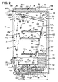
- Fig. 2 is a vertical cross-sectional view of the merchandiser as taken substantially along line 2-2 of Fig. 1;
- Fig. 3 is a greatly enlarged fragmentary cross-sectional view of a product area shelf forming a portion of the primary air distribution system;
- Fig. 4 is an exploded isometric view showing the foam core and seal of the shelf; and
- Fig. 5 is a greatly enlarged fragmentary and partially diagrammatic cross-sectional view, similar to Fig. 2, and showing another portion of the primary cooling system, and also illustrating a foldable product zone wall.
-
- The present invention constitutes improvements in open front, low temperature, multideck product display merchandisers M having an outer cabinet C with a vertical, open front, product display zone Z cooled to its predetermined low temperature condition by a primary air system P and which is further protected by a secondary air system S and a tertiary air system T. As used herein, "low temperature" has reference to frozen food product temperatures of -17.8°C (o°F) and ice cream product temperatures of at least 20.6°c (-5°F), except as may otherwise be specifically described.
- Referring now to the drawings, the cabinet C of the merchandiser M of the present invention includes an insulated outer cabinet having a
base 11, alow front wall 12, a highrear wall 13, atop wall 14 extending forwardly from therear wall 13 andend walls 15 including forwardly extending three-panethermal glass panels 16 with front'trim strips 16a. The front of the frozen food merchandiser N is open between the top of thefront wall 12 and the front of thetop wall 14 for direct accessibility to the interior product zone Z of the merchandiser. - Positioned within the outer cabinet and extending longitudinally between the
end walls 15 is an intermediate cabinet liner which includes a bottom wall orpanel 17 in spaced relation with thebase 11 to provide a bottom outer air flue orduct 18, a front orpanel wall 19 spaced from thefront wall 12 to provide a front flue orreturn duct 20 in communication with thebottom flue 18 as part of the secondary system 5, an insulated rear duct orwall 21 spaced from the back orrear wall 13 to provide a rear duct orflue 22 also in communication with thebottom flue 18, and an insulated top wall orpanel 23 spaced below theouter top wall 14 and defining anair distribution chamber 24 of the secondary air system S. The forward end of the top orupper wall 23 has a projecting depending front member 25 extending away from thetop wall 14, and thetop wall 14 of the outer cabinet also has a short dependingvertical front wall 27 extending downwardly therefrom in forward spaced relation with the front wall member 25 to form a front discharge area orchamber 28 at the front of thechamber 24 of the secondary system S. A relatively wide horizontal section of honeycomb material 29 is constructed and arranged to bridge across or span thefront walls 25 and 27 and form the vertical air discharge means through which non-refrigerated air of the secondary system S is discharged, as will be described more fully. Thewall 23 slopes upwardly from therear panel 21, and the rearward portion of thechamber 24 houses afan 30 or other air circulating means. Thechamber 24 is divided in the usual way by apartition 31 extending linearly the length of the cabinet between therear wall 13 and thetop wall 23 and having spacedopenings 32 in which thefan blades 33 ofplural fans 30 are mounted for efficiently moving air through the entire outer flue network of the secondary system S and in a vertical air curtain SC across the open front of the merchandiser to thereturn duct 20. It will be seen that thechamber 24 is defined by the forwardly. narrowing or convergingwalls baffle 34 is positioned immediately adjacent to the discharge honeycomb or air straightening means 29 so that the discharge area orchamber 28 is defined by a tapering air delivery throat for pressurising and evening air flow distribution longitudinally and laterally of the honeycomb 29. Thus, the return duct orflue 20, bottom andrear flues upper chamber 24 and discharge area andmember 28, 28a, 29 form an air circulatory system for continuously recirculating non-refrigerated air. This secondary system S does not directly cool food products in the display area Z, but forms a protective air wall both during normal refrigeration and defrost cycles of the primary system P. Thefans 30 create a negative pressure through the rear, bottom and front flues to draw air curtain air into thefront flue 20 and to continuously recirculate the air of the secondary system S in maintaining the secondary air curtain SC discharged downwardly across the merchandiser M. - The merchandiser M also includes an innermost cabinet defining the display area Z in which frozen food products are placed for refrigerated merchandising. The inner cabinet also extends linearly the longitudinal extent between the
end walls wall 35 spaced above thebottom wall 17 of the intermediate cabinet to form a lower orfront refrigeration chamber 36. Aninsulated front panel 37 is spaced from thefront wall 19 of the intermediate cabinet and provides a cold air return flue orduct 38 of the primary air system P therebetween, thepanel 37 having an angularly-positionedperforated plate 39 secured to thefront wall 19 and forming the return inlet for thefront flue 38. The inner cabinet also includes a lowerrear panel 41 spaced forwardly from therear wall 21 of the intermediate cabinet and defining a mainrear refrigeration chamber 42 therebetween. - The
return flue 38 is in communication with thefront refrigeration chamber 36, which houses a frontevaporator coil section 43 extending the longitudinal length of the merchandiser M. Therefrigeration chamber 38 is divided by anangular partition 44 having longitudinally spacedopenings 45 forfan blades 46 offans 47 or like air circulating means. The mainrear chamber 42 is in open air flow communication with thefront refrigeration chamber 36 andcoil 43 through thefan openings 45, and therear refrigeration chamber 42 houses the full length mainevaporator coil section 48 through which primary air is moved by thefans 47. Thecoil sections - Still referring to FIG. 2, it is clearly shown that the front and
rear chambers front flue 38 and across thefront coil section 43 and upwardly through therear coil section 48. As seen in FIGS. 1, 2 and 5, the refrigeration system liquid line (not shown) is brought into the base of the merchandiser cabinet in a conventional way and connects to a conventionalthermostatic expansion valve 50 or the like. Theexpansion valve 50 is piped by six parallel coil runs orcircuits 51 of substantially equal length extending across one end of thechambers coil inlet tubes 52 to each of sixvertical circuits 53 through the rearmain coil 48. Refrigerant flow is first distributed to the upper coil tubing of the rear.coil 48 from theexpansion valve 50, which thus will be the coldest zone of the main system and which is also the area of primary air discharge upwardly and outwardly of themain coil section 48 for distribution to cool the product zone Z. Refrigerant flow is downwardly in therear coil 48 in reverse flow to the direction of primary air movement through the coil during the refrigeration cycle. The six separatevertical coil circuits 53 are connected in pairs at the bottom of the rear coil to three horizontal refrigerant circuits 54 which connect to threecorresponding coil circuits 55 of thefront coil 43, which in turn are connected to a suction line take-off in a usual manner for returning expanded vaporized refrigerant to the refrigeration system compressors (not shown). The conduit size of the sixdistribution circuits 51 andrear coil tubes 53 is relatively smaller than the conduit size of the three connection circuits 54 andfront coil tubes 55 to eliminate pressure drop in the evaporator coils except as typically controlled through the entire circuitry from theexpansion valve 50. For instance, the sixdelivery circuits 51 andrear coil tubing 53 may be sized at 15.9mm '5/8 inch', and the three connection circuits 54 andfront coil tubing 55 may be sized at 19mm ' 3/4 inch'. Thus, the refrigeration cooling means for the primary air system P produces the coldest coil temperatures at the point of primary air discharge from therear coil section 48, and slightly warmer coil temperatures will prevail at the return air lead-in to thefront coil 43. In order to maintain the product area at about -17.8°C (0°F), for frozen foods, the temperature of the primary air exiting therear coil 48 must be in the range of -18.9°c(-2°F), to -20.6°c(-5°F), and optimally at about -19.4°c(-3°F), which is produced by rear coil temperatures in the range of -20.6°c(-5°F), to -22.2°c(-8°F), in the present merchandiser. This contrasts with prior coil temperatures of the magnitude of -28.9°c(-20°F), to produce -23.3°c(-10°F), exit air temperatures in order to achieve and maintain a -17.8°C (0°F), product zone. Similarly, in the case of ice cream, the rear coil operates at about -24.4°c(-12°F), to -26.1°c(-15°F), to produce exit air temperatures of about -23.3°c(-10°F), to -24.4°c(-12°F), to maintain the product area target temperature of at least -20.6°c(-5°F), which contrasts with prior ice cream merchandisers requiring about -34.4°c (-30°F), coil temperatures to produce exit air temperatures of -27.7°c(-18oF), to -28.9°c(-20°F). It will be clear that theevaporator coils front coil 43 is wider than the fin spacing of therear coil 48 so that the front coil functions primarily as a "frost catcher" to initially pre-cool recirculated air curtain air from the open front of the display area Z and start to remove its moisture content in the form of ice on the fins without bridging across and blocking primary air flow through this coil section. The counterflow refrigerant distribution in thecoil sections 48 to 43 (relative to the direction of air flow) results in substantially even ice or frost build up on the fins and more even air distribution longitudinally in the air system channels. - The presently preferred from of defrost of the
main refrigeration coils defrost heaters 57 are disposed vertically above therear coil 48. A defrost cycle is carried out by reverse air flow operation of theprimary fans 47 in the primary system P to bring the heat downwardly through therear coil 48 then forwardly through thefront coil 43. The efficiency of the present merchandiser is designed to reduce the number of defrost cycles (e.g. from 3 to 2) and to shorten each defrost duration from about 40 minutes heretofore to about 20 to 30 minutes while employing about one-half the amount of electric heat previously required for defrosting. Thus, even with larger primary coils, the use of substantially less electric wattage for shorter and less frequent defrost periods contributes to the high efficiency of the present merchandiser. It will be understood that hot gas defrost or latent heat defrost may be employed in lieu of electric heat defrost, as will be readily apparent to those skilled in the art. In the case of gas defrost, the primary air circulation is still reversed and the defrost duration will be about 15 to 20 minutes. - It is now apparent that, in the normal refrigeration cycle, air is drawn into the
return flue 38 by the negative pressure developed by thefans 47 and passed through thecoils 43, and is then forced upwardly through therear coils 48 where the air is fully refrigerated to the elevated low exit temperatures of -20.6°C (-5°F) to -18.9°C (-2°F), required for maintaining food products in frozen condition at -17.8°c (-0°F). "Elevated low coil temperature" herein means that the multideck, open front merchandiser M and its primary air refrigeration and circulation system P ate constructed and arranged to keep the product zone Z and food products therein at the designated target temperature (of -17.8°c (0°F), for frozen food products or -20.6°C (-5°F), for ice cream products) while operating at a temperature of only a few degrees colder - as contrasted with conventional prior merchandisers that generally operate at a much lower coil temperatures. It is known that each degree of lower coil temperatures results in more moisture removal and icing in the coil which by itself results in lost refrigeration capacity, additional or longer defrosts nd high product temperatures above -17.8°C (0°F). In the present invention the main coil size is increased about 25% to 40% in order to achieve more efficient refrigeration and better air control. - The
bottom panel 35 and front andrear panels end walls 15 of the outer cabinet define a lower well 58 of the display area Z in which food products may be placed. As shown best in Fig. 5, thefront part 35a of thebottom panel 35, extending a substantial distance back from the verticalfront panel 37, is thinner than therearward portion 35b to accommodate a movableglass shelf panel 60. Thispanel 60 is hinged at its longitudinal forward margin for upward swinging movement from a horizontal shelf-forming position in which thepanel 60 lies in the recessedthinner area 35a of the bottom panel 35 (Fig. 2) and a vertical wall-forming position in which thepanel 60 extends upwardly parallel to thefront panel 37, but above thelower front wall 12 and lower part of and wall 15 (Fig. 15). In this way the area of the well 58 can be substantially deepened for certain merchandising purposes, and the glass panel affords full visibility. It will be clear that the merchandiser M is of the multideck-type having a plurality of vertically spaced horizontally extendingshelves 61 in the upper portion of the product display zone Z, but that the shorterlower shelf 61a normally accommodating access to the shallow well configuration of Fig. 2 is removed in order to raise the shelf panel to its front wall forming position. - The primary air refrigeration and distribution system P is designed to maintain optimum product temperatures with a minimum change from the operating coil temperatures (e.g., a change of about -16.7°c(2°F) to -15°(5°F). Primary air is discharged upwardly in the
rear chamber 42 through the mainrear coil section 48 and into a rear air distribution flue orduct 62 that is vertically disposed between the intermediate insulatedrear wall 21 and a slopingfront panel 63, which also forms the rear or back wall of the upper display area Z. The primary air distribution system P has a top flue orduct 64 delineated by an insulated top panel orwall 65, which extends forward from therear duct 62 and terminates at a taperingfront discharge chamber 66 defined, in part, by anair control baffle 67 connected between the depending wall 25 and the insulatedtop wall 23 of the intermediate cabinet to backpressure primary air and even out its longitudinal distribution for discharge through anair straightening honeycomb 68 or the like to form a primary air curtain PC or low temperature air across the open front of the display area Z. - The
lower end 69 of the upperrear panel 63 connects to the upper end of the lowerrear panel 41 below the upper air discharge end of therear coil 48. A primary air control baffle 7- projects angularly from thepanel 21 to direct air flow from thecoil 48 forward as well as upwardly into the wide bottom area of therear duct 62, and another angular baffle orair deflector 71 connects to the opposed surface of therear panel wall 63 to project angularly downwardly toward the leading air discharge edge of thecoil 48 and substantially parallel with therear panel baffle 70 to define an air proportioning throat or control means 70a. - The upper
rear panel 63 is spaced from therear panel 21 of the intermediate cabinet by suitable means including a center divider wall andshelf support 73 disposed vertically between theend walls 15 and dividing the rear cold air delivery flue orduct 62 into at least two sections. Therear panel 63 is provided with a plural series of air outlet openings ormoire 74, and upper series of moire for theupper shelves 61 each have a baffle orair deflector 75 positioned to extend into therear duct 62 and deflect a portion of the primary air stream through the moire for delivery to thehollow shelves 61 as part of the primary air system P. As shown best in FIGS. 3 and 4, theshelves 61 are adjustably mounted on therear wall 63 and extend forwardly therefrom into the upper portion of the display area Z. Theshelf support stanchions 73 are formed on thecenter wall divider 73 and at each end of the display area to adjustably support theshelves 61 within a predetermined vertical range defined by the location of themoire 74 and shelf sealing means 76 to be described. - In Fig. 3 it will be seen that each
shelf 61 has a horizontal shelf plate ordeck 77 with aback plate 78 secured at an angle to accommodate the slope of therear panel 63. Theshelf 61 also has abottom metal panel 79 in spaced relation with theupper panel 77, and it is reinforced with longitudinal structural hat sections ormembers 80 to support substantial product weights on the shelf. The usualshelf mounting brackets 81 with bayonet tabs 81a are provided for adjustably mounting theshelf 61 on the shelf stanchions 73 at the center and ends of the merchandiser. The space between the upper and lower shelf plates orpanels longitudinal discharge chamber 83 at the front of each shelf, andlongitudinal honeycomb sections 84 are provided for air control from thedischarge chamber 83 at each shelf level. However, it is to be understood thatselective shelves 61 may be removed from the product zone Z without adversely affecting the operation of the merchandiser or the maintenance of low product temperatures therein. - The space between the upper and
lower shelf panels foam shelf core 85 having a continuousbottom panel 85a with longitudinally spacedupstanding ribs 85b which extend the depth of theshelf 61 and define the channel or parallel air tunnel means 82 for conveying primary air from themoire inlets 74 to the shelf air discharge honeycomb 84 (see FIGS. 3 and 4). Theshelves 61 sealably engage thepanel 63 and, for that purpose, theback plate 78 of each shelf has the sealing means 76 attached to provide an air seal framing around the channel means 82. The sealing means 76 include extruded frame pieces ormembers 76a of rectangular cross-section assembled into a rectangular frame attached to thecore member 85 or to theback plate 78 itself, and aresilient sealing member 76b is attached to or formed integral with the extrudedframe pieces 76a. Theshelf 61 is adjustable vertically within the confines of the air inlet opening orwindow 76c defined by the frame, and theseal member 76b is compressed into sealing engagement against the rear panelfront surface 63 to maintain primary air flow from the primaryrear duct 62 into theshelf tunnels 82 as diverted or proportioned by thebaffles moire openings 74. It will be noted that a removable strip of magnetic tape 86, FIG. 5, may be applied to cover themoire section 74 whenever ashelf 61 is removed to prevent primary air leakage into the rear portion of the display zone Z next to thepanel 63 although some amount of shelf discharge air will circulate by convection rearwardly over the product on the next lower shelf. It will also be noted that the top deck orplates 77 of theshelves 61 afford conductive cooling of the products placed thereon, but that thelower panel 79 is insulated by thebottom core wall 85a to obviate moisture migration and frost buildup under the shelves. - Referring again to FIG. 2, the tertiary air system T is an ambient air system mounted on the exterior of the main outer cabinet C. The tertiary system T includes a longitudinal
air moving housing 88 attached to the back of thetop wall 14 and having plural filteredair intake openings 89 in communication with amain intake chamber 90, which connects toplural blowers 91 preferably of the tangential type. Therear housing 88 and blower outlet therefrom connect to a forwardly extendingair duct wall 92 defining thedelivery duct 92a for conveying ambient air from theblowers 91 to the front of the merchandiser M. This duct tapers or is baffled to define a narrowingair discharge area 93, and anair control honeycomb 94 through which a tertiary air curtain TC of ambient air is formed across the open front outwardly of the secondary air curtain SC. The merchandiser M is also provided with anupper light canopy 95 that is constructed and arranged to illuminate the product zone Z, and may be telescopically or otherwise adjustable onstruts 95a to be extended forwardly to modify the lighting effect. - In the operation of the merchandiser M, the primary system P, the secondary system S and the tertiary system T cooperate to provide the desired low temperatures in the display area Z for keeping food products in frozen condition and for providing an inner cold front or wall of low temperature air with a temperature gradient outwardly to ambient that obviates the necessity for doors or glass panels across the front of the
merchandiser shelves 61. The glass retaining wall orbarrier 60 is only turned up above the lowfront wall 12 of the outer cabinet as needed to enlarge the well volumetrically. The three air systems also reduce to a minimum the amount of ambient room temperature air that becomes entrained or intermixed with the low temperature air wall PC so that the merchandiser can operate efficiently and perform its function of maintaining low frozen food product temperatures. In addition, moisture is substantially eliminated from the display area Z and condensation, and consequent icing, is substantially reduced on the evaporator coils 43 and 48 of the primary system P. - In the operation of the primary system P, the
main fans 47 draw cold air into thereturn duct 38 from the display area Z and through thefront coil section 43, and then pushes this pre-cooled and dehumidified air upwardly through the largerear coil 48 inchamber 42 where the temperature of the air is reduced to the requisite optimum temperature, e.g. -19.4°C (-3°F) for frozen food. The primary air stream forced through thecoil 48 is diverted byrear flue baffle 70 and the major portion of the air passed upward inrear delivery duct 62. A small portion of the coil air is deflected downwardly bybaffle 71 into thelower shelf duct 82 and other portions of air are diverted at each shelf level with the final air portion flowing forwardly and upwardly inupper duct 64 to theprimary honeycomb 68. It will be seen that therear duct 62 forms a long upward channel with convergingwalls shelf duct 82 is substantially uniform and about one-half of the volume of air flow delivered through thetop duct 64 for downward discharge through theprimary honeycomb 68 to form the low temperature air curtain PC. Thus, primary air is discharged at thefront top 68 of the display area and at the front only of eachshelf 61 to provide convection cooling of the display area of the next lower shelf without distribution of any air from the rear or intermediate shelf location, whereby by discharging the same temperature air at multiple vertical levels from top to bottom in the display zone, the temperature will be kept substantially constant throughout. - The main or
primary system fans 47 create a negative suction or return air velocity of about 3.05 m/s (600 fpm), and this air velocity is reduced at the rear dischargeduct control throat 70a to about 1.52 m/s (300 fpm) which is maintained during vertical air distribution by the tapering rear duct configuration. The air velocity of the primary air is reduced as it translates laterally at thedeflectors shelves 61 to the discharge honeycombs 84 thereof. This reduction in air velocity may also result in an air speed gradient at the respective shelf levels from bottom to top with the discharge at thelower shelf 61a being about 1.27 m/s (250 fpm) and the successively shelves having successively lower air speeds up to an uppershelf air discharge 84 of about 0.89 m/s (175 fpm). The first primary air curtain PC is discharged from themain system honeycomb 68 with a reverse taper or air speed gradient from its back face to its front face of about 1.02 m/s (200 fpm) to 1.27 m/s (250 fpm) established by theair control baffle 67. The lower speed or reduction in velocity established at the back or rearward face of the air curtain PC accommodates merger with the upper shelf discharge air and then each successively lower shelf-to-shelf air curtain with minimum turbulence at the interfaces of the curtains to enhance the cooling at the discrete shelf zones by the respective associated curtains. - The secondary system S has a discharge honeycomb of about twice the width as the primary system discharge 68 to provide a wide non-refrigerated air curtain SC, and the curtain SC also preferably has a reverse taper or air speed gradient with a rear face velocity of about 1.27 m/s (250 fpm) and a front or outer face of about 1.52 m/s (300 fpm). The tertiary system T discharges a narrower width curtain TC similar to the primary air curtain PC and with a box profile of about 1.52 m/s ( 300 fpm). Thus, the air speeds at the interface of the adjacent curtains will be about the same to reduce intermixing and turbulence. In the preferred embodiment disclosed, the ratio of the shelf air curtains to the primary curtain PC to the secondary system curtain SC to the tertiary curtain will be about 1:2:4:2. The curtain discharged at each successive shelf front contributes to the formation of widening primary curtain PC. The return air temperature of the primary system P at the
return duct 38 will be substantially lower than prior art merchandisers. - During defrost, the normal refrigeration cycle of the primary system coils 48 and 43 is discontinued and the defrost means (e.g., electric or gas) is initiated along with a reversal of the primary fan direction to draw heated defrost air downwardly (from the Calrod heaters 57) through the rear and
front coil sections front duct 38. This practice is well-known in the art. However, the secondary air system S and tertiary system T continue to function in their normal downward curtain formation to shield the product zone Z and to create at least a partial short circuit of heated primary air from thereturn grill 39 back downward into thesecondary return flue 20. The defrost parameters are highly efficient and the duration of each defrost cycle has been substantially shortened by about one-half to one-third, e.g., from about 40 minutes to 20 to 30 minutes for electric at about one-half of the wattage required in prior art systems, as previously described. - The present merchandiser is highly efficient in operation and provides a large accessible product display area Z for displaying frozen food products while occupying a minimum floor space. It is to be understood that the foregoing description and accompanying drawing have been given only by way of illustration and example, and that changes and modifications in the present disclosure, which will be readily apparent to all skilled in the art, are contemplated as within the scope of the present invention, which is limited only by the scope of appended claims.
Claims (14)
- A refrigerated merchandiser (M) having a cabinet (C) with an open front product display area (Z), a primary air system (P) comprising evaporator means (43,48) constructed and arranged for refrigerating primary air to low refrigeration temperatures and air moving means (47) for circulating primary air through the evaporated means and an air distribution duct (62,64) in a first refrigerating direction to maintain a substantially uniform low target temperature throughout the display area, said primary air circulating means forming a first primary air curtain (PC) discharged downwardly across the open front of the display area from the top of the merchandiser cabinet, secondary air system means (S) constructed and arranged for forming a secondary air curtain (SC) discharged downwardly across the open front of the display area immediately outwardly of said primary air curtains, and defrost means (57) for periodically defrosting said evaporator means (43,48), and being characterised by shelf means (61,61a) adjustably supported in said display area and including air channelling duct means (82) constructed and arranged to channel primary air from said distribution duct (62,64) and discharge at least one additional curtain of primary air downwardly from the front of the shelf means (61,61a) immediately inwardly of and substantially parallel to the first primary air curtain at the open front of the display area (Z), the air flow of said primary air curtains being the only positive air movement at said display area (Z).
- A merchandiser as claimed in claim 1, in which said shelf means comprises a plurality of vertically adjustable shelves (61,61a) discharging a plurality of vertically spaced primary air curtains immediately inwardly of said first primary air curtain to respectively cool discrete shelf zones (61,61a) throughout the display area, each of said shelves having upper and lower shelf walls (77,79) at least one of which is uninsulated and in heat exchange relation with the air channeling duct means (82).
- A merchandiser as claimed in claim 2, in which said first primary air curtain is substantially wider than said primary air curtain discharged at said shelf means, and means (71,75) for producing a velocity gradient of the plural primary air curtains in which the lower shelf discharges the fastest air curtain and the uppermost shelf discharges the slowest air curtain.
- A merchandiser as claimed in claim 1, 2 or 3, in which said primary air system includes means (67) for producing a tapering velocity profile across said first air curtain with the air movement at the inner face adjacent to said display zone being at a slower velocity than the outer face thereof.
- A merchandiser as claimed in claim 4, in which said secondary air system means comprises secondary air circulating means (30) forming said secondary air curtain (SC), and means (34) associated therewith for producing a tapering velocity profile of said secondary air curtain (SC) with the air movement at the inner face being slower than at the outer face, and the said air curtain velocity at the inner face of the secondary air curtain (SC) being substantially the same as the air velocity at the outer face of the first primary air curtain (PC).
- A merchandiser as claimed in claim 5, which includes a third air system (T) constructed and arranged for forming a third air curtain (TC) of ambient air across the open front of the display area outwardly of the secondary air curtain (SC), the air curtain velocity at the inner face of the third air curtain (TC) being substantially the same as the air velocity at the outer face of the secondary air curtain (SC).
- A merchandiser as claimed in claim 6, in which the secondary air curtain (SC) is substantially wider than the first primary air curtain, and the third air curtain (TC) is substantially narrower than the secondary air curtain (SC).
- A merchandiser as claimed in claims 2 or 3, in which one of the walls of said air channeling means includes an imperforate insulated panel (85a) and a plurality of vertical ribs (85b) projecting therefrom to engage the insulated shelf means wall thereby to define a plurality of elongated air tunnels (82) extending across said shelf means and forming an air discharge chamber (83) at the front edge of the air channeling means, and air straightening means (84) constructed and arranged at said discharge chamber for forming said primary air curtain therefrom.
- A merchandiser as claimed in claim 8, in which said shelves are mounted to extend from a rear panel (63) of the display area, and air control means (75) for distributing refrigerated primary air from the evaporator means and distribution duct through the elongated air tunnels (82) comprising air passage means (74) through the rear panel duct wall, and shelf sealing means (76) constructed and arranged to sealably enclose the shelf air tunnels in air flow communication with the rear distribution duct.
- A merchandiser as claimed in claims 1 or 2, in which the display area (Z) includes a lower well zone (58) with a product supporting deck panel means (35), and a portion (60) of said deck panel means being movable to a vertical front wall forming position.
- A merchandiser as claimed in claim 1, in which said evaporator means (43,48) comprises a split evaporator coil having a first main coil section (48) and a second pre-cooler coil section (43), and said air moving means circulating primary air in said first refrigerating direction sequentially through said pre-cooler and main coil sections, and refrigerant distribution means (51,54) for feeding said split coils counterflow to the first direction of primary air flow therethrough.
- A merchandiser as claimed in claim 11, in which said refrigerant distribution means comprises expansion means (50), a plurality of separate and parallel first coil circuits (51) forming said main coil section and operatively connected to the expansion means, a fewer number of separate and parallel second coil circuits (54) forming said pre-cooler coil section and being connected and arranged to receive substantially equal amounts of expanding refrigerant flow from the first main coil circuits.
- A merchandiser as claimed in claim 11, in which said main coil section is at least four times larger than the pre-cooler coil section with twice the number of first coil circuits as the second coil circuits, and in which the refrigerant tubing of the first coil circuits is smaller than the refrigerant tubing of the second coil circuits.
- A merchandiser as claimed in claim 1, in which said primary (PC) and secondary (SC) air curtains are maintained in substantially side-by-side parallel air flow relationship during normal refrigerating operations and have adjacent inner and outer air return means (38,20) in said cabinet for receiving the respective air curtains into the cabinet (C) during refrigerating operations, and means (47) for reversing said primary air moving means (47) for circulating primary air through the evaporator means (43,48) in a second reverse air flow defrosting direction while maintaining the normal operation of said secondary air system means (S), the primary air flow during reverse air flow defrosting operations being discharged outwardly from the inner air return means (38) for short circuited return with the downwardly flowing secondary air curtain (SC) into the outer air return means (20) of the cabinet (C).
Applications Claiming Priority (5)
| Application Number | Priority Date | Filing Date | Title |
|---|---|---|---|
| US08/060,154 US5345778A (en) | 1993-05-07 | 1993-05-07 | Low temperature display merchandiser |
| US60154 | 1993-05-07 | ||
| US155190 | 1993-11-22 | ||
| US08/155,190 US5357767A (en) | 1993-05-07 | 1993-11-22 | Low temperature display merchandiser |
| PCT/US1994/004595 WO1994026154A1 (en) | 1993-05-07 | 1994-04-26 | Low temperature display merchandiser |
Publications (3)
| Publication Number | Publication Date |
|---|---|
| EP0696893A1 EP0696893A1 (en) | 1996-02-21 |
| EP0696893A4 EP0696893A4 (en) | 1997-01-29 |
| EP0696893B1 true EP0696893B1 (en) | 2002-03-13 |
Family
ID=26739627
Family Applications (1)
| Application Number | Title | Priority Date | Filing Date |
|---|---|---|---|
| EP94916586A Expired - Lifetime EP0696893B1 (en) | 1993-05-07 | 1994-04-26 | Low temperature display merchandiser |
Country Status (7)
| Country | Link |
|---|---|
| US (1) | US5357767A (en) |
| EP (1) | EP0696893B1 (en) |
| CN (1) | CN1098663C (en) |
| AU (1) | AU6819894A (en) |
| CA (1) | CA2161956A1 (en) |
| DE (1) | DE69430120D1 (en) |
| WO (1) | WO1994026154A1 (en) |
Cited By (1)
| Publication number | Priority date | Publication date | Assignee | Title |
|---|---|---|---|---|
| WO2014029612A1 (en) | 2012-08-22 | 2014-02-27 | Aht Cooling Systems Gmbh | Cooling unit |
Families Citing this family (93)
| Publication number | Priority date | Publication date | Assignee | Title |
|---|---|---|---|---|
| US5517826A (en) * | 1995-03-14 | 1996-05-21 | Hussmann Corporation | Refrigerated merchandiser with modular external frame structure |
| BR9605934A (en) * | 1995-03-14 | 1998-12-29 | Hussmann Corp | Refrigerated counter with modular evaporating coils and eepr control |
| US5870903A (en) * | 1996-08-15 | 1999-02-16 | Stein Industries, Inc. | Air circulation unit for refrigerated cases |
| NO963516A (en) * | 1996-08-23 | 1997-11-24 | Norcool As | Device for refrigeration systems |
| DE19639108C1 (en) * | 1996-09-24 | 1998-01-22 | Hertel Guenther | Refrigerated shop counter |
| US5860289A (en) * | 1997-10-22 | 1999-01-19 | Floratech Industries, Inc. | Open floral display case |
| US5924297A (en) * | 1997-11-03 | 1999-07-20 | Hussmann Corporation | Refrigerated merchandiser with modular evaporator coils and "no defrost" product area |
| FR2778733B1 (en) * | 1998-05-12 | 2000-08-18 | Austria Haus Technik Aktienges | SHELF-EXCHANGERS FOR SALE REFRIGERATED FURNITURE AND REFRIGERATED FURNITURE USED BY SUCH SHELVES |
| ES1041549Y (en) * | 1998-11-13 | 2000-01-01 | Mellado Antonio Criado | IMPROVED FURNITURE FOR FOOD EXPOSURE AND CONSERVATION. |
| FR2786999B1 (en) | 1998-12-09 | 2001-02-23 | Nevoret Concept | REFRIGERATION SALES FURNITURE |
| US8151587B2 (en) * | 2001-05-04 | 2012-04-10 | Hill Phoenix, Inc. | Medium temperature refrigerated merchandiser |
| US6981385B2 (en) | 2001-08-22 | 2006-01-03 | Delaware Capital Formation, Inc. | Refrigeration system |
| US6889518B2 (en) * | 2001-08-22 | 2005-05-10 | Delaware Capital Formation, Inc. | Service case |
| JP4322120B2 (en) * | 2001-12-27 | 2009-08-26 | Gac株式会社 | Storage device |
| US6701735B1 (en) * | 2002-10-04 | 2004-03-09 | Carrier Commercial Refrigeration, Inc. | Multi deck merchandiser with horizontal air curtains |
| US6701736B1 (en) | 2002-12-31 | 2004-03-09 | Gamon Plus, Inc. | Refrigerated merchandising apparatus |
| USD483777S1 (en) | 2002-12-31 | 2003-12-16 | Gamon Plus, Inc. | Refrigerated merchandiser housing |
| JP2006514574A (en) | 2003-01-07 | 2006-05-11 | キャリア・コマーシャル・リフリージレーション・インコーポレーテッド | Construction method of air curtain separation barrier |
| US6722149B1 (en) * | 2003-01-07 | 2004-04-20 | Carrier Commercial Refrigeration, Inc. | Refrigerated display merchandiser |
| US7162882B2 (en) * | 2003-01-07 | 2007-01-16 | Carrier Corporation | Multi-band air curtain separation barrier |
| US20040163401A1 (en) * | 2003-02-26 | 2004-08-26 | Alahyari Abbas A. | Refrigerated display merchandiser with improved air curtain |
| US7159413B2 (en) * | 2003-10-21 | 2007-01-09 | Delaware Capital Formation, Inc. | Modular refrigeration system |
| BR0306232A (en) * | 2003-11-28 | 2005-07-19 | Multibras Eletrodomesticos Sa | Improvement in cabinet cooling system |
| US7357000B2 (en) * | 2003-12-05 | 2008-04-15 | Dover Systems, Inc. | Display deck for a temperature controlled case |
| KR20060127018A (en) * | 2004-01-06 | 2006-12-11 | 캐리어 커머셜 리프리저레이션, 인크. | Refrigerated showcase with improved air curtain |
| US7451603B2 (en) * | 2004-03-22 | 2008-11-18 | General Mills, Inc. | Portable cooled merchandizing unit |
| JP4666956B2 (en) * | 2004-06-14 | 2011-04-06 | 三洋電機株式会社 | Cooling storage |
| DE102004033071A1 (en) * | 2004-07-06 | 2006-01-26 | Linde Kältetechnik GmbH & Co. KG | refrigerated |
| US7121104B2 (en) * | 2004-09-23 | 2006-10-17 | Delaware Capital Formation, Inc. | Adjustable shelf system for refrigerated case |
| WO2006039043A1 (en) * | 2004-09-30 | 2006-04-13 | Carrier Corporation | Curtain air admission assembly |
| US7934384B2 (en) | 2004-10-22 | 2011-05-03 | General Mills, Inc. | Portable cooled merchandizing unit with customer enticement features |
| JP2006242449A (en) * | 2005-03-02 | 2006-09-14 | Sanden Corp | Showcase |
| JP2006258323A (en) * | 2005-03-15 | 2006-09-28 | Sanden Corp | Showcase |
| WO2006115824A2 (en) * | 2005-04-25 | 2006-11-02 | Delaware Capital Formation, Inc. | Air curtain system for a refrigerated case |
| WO2006115501A2 (en) * | 2005-04-27 | 2006-11-02 | Carrier Corporation | Refrigerator case wall structure |
| US20090301121A1 (en) * | 2005-05-24 | 2009-12-10 | Carrier Corporation | Refrigerator Case Top Duct Member |
| US20070022667A1 (en) * | 2005-07-28 | 2007-02-01 | Gemtron Corporation | Product display case door frame having an integrated raceway |
| US20080282719A1 (en) * | 2005-12-07 | 2008-11-20 | Fung Kwok K | Airflow Stabilizer for Lower Front of a Rear Loaded Refrigerated Display Case |
| JP2007260223A (en) * | 2006-03-29 | 2007-10-11 | Sanyo Electric Co Ltd | Open showcase |
| CN101074820B (en) * | 2006-05-16 | 2011-06-08 | 泰州乐金电子冷机有限公司 | Refrigerator |
| US20100212343A1 (en) * | 2006-06-20 | 2010-08-26 | Hill Phoenix, Inc. | Refrigerated case with low frost operation |
| US20070298703A1 (en) * | 2006-06-23 | 2007-12-27 | Chih-Feng Chen | Insect proof wind generating device |
| US20090205351A1 (en) * | 2006-10-26 | 2009-08-20 | Kwok Kwong Fung | Secondary airflow distribution for a display case |
| US7637031B2 (en) * | 2007-06-26 | 2009-12-29 | Gm Global Technology Operations, Inc. | Evaporator core drying system |
| CN101347297A (en) * | 2007-07-19 | 2009-01-21 | 浙江德宝电器有限公司 | Single-chamber double-mode refrigeration vertical type ice-cream show cabinet |
| US20090084125A1 (en) * | 2007-09-28 | 2009-04-02 | Carrier Corporation | Refrigerated merchandiser system |
| US20100024446A1 (en) * | 2008-08-04 | 2010-02-04 | Hussmann Corporation | Refrigerated merchandiser with dual air curtain |
| JP2010057806A (en) * | 2008-09-05 | 2010-03-18 | Sanyo Electric Co Ltd | Low temperature showcase |
| US9526354B2 (en) * | 2008-09-11 | 2016-12-27 | Hill Phoenix, Inc. | Air distribution system for temperature-controlled case |
| US8468836B2 (en) * | 2008-11-12 | 2013-06-25 | General Mills, Inc. | Portable thermoelectric cooling/heating unit and related merchandizing system |
| USD615319S1 (en) | 2008-11-12 | 2010-05-11 | General Mills, Inc. | Product merchandizing unit |
| WO2010068367A1 (en) * | 2008-12-10 | 2010-06-17 | Hill Phoenix, Inc. | Open front display case with secondary air curtain |
| US8863541B2 (en) * | 2009-06-10 | 2014-10-21 | Hill Phoenix, Inc. | Air distribution system for temperature-controlled case |
| KR101876581B1 (en) | 2010-03-29 | 2018-07-09 | 어플라이드 디자인 앤드 엔지니어링 리미티드 | Improvements in or relating to refrigerated display appliances |
| US9675185B2 (en) | 2010-04-23 | 2017-06-13 | Hussmann Corporation | Refrigerated merchandiser with shelf air discharge |
| US8713954B2 (en) * | 2010-08-23 | 2014-05-06 | Hill Phoenix, Inc. | Air curtain system for an open-front refrigerated case with dual temperature zones |
| RU2013139341A (en) * | 2011-01-26 | 2015-03-10 | Дьюк Мэньюфэкчуринг Ко. | SHOWCASE |
| NZ611793A (en) * | 2011-06-30 | 2013-10-25 | Hussmann Corp | Apparatus for disease detection |
| CN102379580B (en) * | 2011-08-12 | 2014-01-22 | 银都餐饮设备股份有限公司 | Anti-condensing closed-type display cabinet |
| WO2013029686A1 (en) * | 2011-09-02 | 2013-03-07 | Carrier Corporation | Refrigerated sales furniture |
| US9285153B2 (en) | 2011-10-19 | 2016-03-15 | Thermo Fisher Scientific (Asheville) Llc | High performance refrigerator having passive sublimation defrost of evaporator |
| US9310121B2 (en) | 2011-10-19 | 2016-04-12 | Thermo Fisher Scientific (Asheville) Llc | High performance refrigerator having sacrificial evaporator |
| USD722244S1 (en) | 2012-01-12 | 2015-02-10 | Duke Manufacturing Co. | Merchandiser facade |
| US9188369B2 (en) | 2012-04-02 | 2015-11-17 | Whirlpool Corporation | Fin-coil design for a dual suction air conditioning unit |
| DE102012107711B4 (en) | 2012-08-22 | 2016-09-08 | Aht Cooling Systems Gmbh | cooling rack arrangement |
| DE102012107713B4 (en) | 2012-08-22 | 2018-02-15 | Aht Cooling Systems Gmbh | refrigerated |
| DE102012022422A1 (en) | 2012-11-16 | 2014-05-22 | Edgar Hakemann | Self-service sale furniture e.g. refrigerated display case, for storing e.g. warm food products in bar, has flap operated in storage position in which flap is positioned within sales region such that opening is freely accessible |
| DE202012010995U1 (en) | 2012-11-19 | 2012-11-28 | Edgar Hakemann | Sales furniture for self-service |
| US9228762B2 (en) * | 2013-02-28 | 2016-01-05 | Whirlpool Corporation | Refrigeration system having dual suction port compressor |
| US9687088B2 (en) * | 2013-04-08 | 2017-06-27 | Heatcraft Refrigeration Products Llc | Deflector for display cases |
| ITMI20130768A1 (en) * | 2013-05-10 | 2014-11-11 | Goppion Spa | SHOWCASE WITH DIFFERENTIATED CLIMATE AREAS |
| GB201308437D0 (en) * | 2013-05-10 | 2013-06-19 | Applied Design & Eng Ltd | Shelves for open-fronted display units |
| GB201308439D0 (en) | 2013-05-10 | 2013-06-19 | Applied Design & Eng Ltd | Shelves for open-fronted display units |
| CN103720243A (en) * | 2013-12-19 | 2014-04-16 | 大连三洋冷链有限公司 | Display cabinet with microcirculation wind curtain air supply under shelf |
| US9737156B2 (en) * | 2013-12-23 | 2017-08-22 | Hussmann Corporation | Zone cooling in a refrigerated merchandiser |
| US20150230626A1 (en) * | 2014-02-14 | 2015-08-20 | Hussmann Corporation | Leveler mechanism for a merchandiser |
| US9986822B2 (en) * | 2014-05-01 | 2018-06-05 | The Boeing Company | Method and apparatus for cooling an airline galley cart using a skin heat exchanger |
| US20150314874A1 (en) * | 2014-05-01 | 2015-11-05 | The Boeing Company | Optimally configured air-flow galley cart |
| US11085455B1 (en) * | 2014-08-11 | 2021-08-10 | Delta T, Llc | System for regulating airflow associated with product for sale |
| KR20160059417A (en) * | 2014-11-18 | 2016-05-26 | 후지 덴키 가부시키가이샤 | Showcase |
| JP6732780B2 (en) * | 2015-03-20 | 2020-07-29 | ペプシコ・インク | Cooling system and method |
| US10119745B1 (en) * | 2017-09-17 | 2018-11-06 | Heatcraft Refrigeration Products Llc | Air deflectors with flexible hinge for refrigerated display cases |
| US11559147B2 (en) * | 2019-05-07 | 2023-01-24 | Carrier Corporation | Refrigerated display cabinet utilizing a radial cross flow fan |
| EP3804575B1 (en) * | 2019-10-09 | 2024-02-14 | Fri-Jado B.V. | System comprising a display unit for storing and displaying food products, and multiple shelves, and method for storing and displaying food products in a display unit |
| US11576501B2 (en) * | 2019-11-08 | 2023-02-14 | Hill Phoenix, Inc. | Guide vane for refrigerated display case |
| GB2592047A (en) * | 2020-02-13 | 2021-08-18 | Aerofoil Energy Ltd | Improvements to open display refrigerators |
| WO2021162653A1 (en) * | 2020-02-14 | 2021-08-19 | Çağlayan Soğutma Sanayi̇ Ve Ti̇caret Li̇mi̇ted Şi̇rketi̇ | Refrigeration appliance with multiple air curtains |
| US11906209B2 (en) | 2020-02-19 | 2024-02-20 | Hill Phoenix, Inc. | Thermoelectric cooling system |
| CN111392240B (en) * | 2020-03-18 | 2021-07-27 | 上海长征医院 | A smart food sample storage cabinet |
| CN114688782A (en) * | 2020-12-28 | 2022-07-01 | 深圳市凯润机电设备有限公司 | An energy efficient storage refrigerator |
| EP4246065A1 (en) | 2022-03-18 | 2023-09-20 | Industrie Scaffalature Arredamenti - Isa Società Per Azioni | Cassette unit for refrigerated display cabinets with an airflow reversal system |
| IT202200008504A1 (en) * | 2022-04-28 | 2022-07-28 | De Rigo Refrigeration S R L | DISPLAY FOR REFRIGERATED PRODUCTS |
| KR102850792B1 (en) * | 2022-10-18 | 2025-08-27 | 주식회사 디에이치글로벌 | Duct system for showcase |
Family Cites Families (21)
| Publication number | Priority date | Publication date | Assignee | Title |
|---|---|---|---|---|
| US2157145A (en) * | 1936-10-31 | 1939-05-09 | Westinghouse Electric & Mfg Co | Air conditioning apparatus |
| US2836039A (en) * | 1955-09-19 | 1958-05-27 | Weber Showcase & Fixture Co In | Refrigerated self-service showcase |
| US3134243A (en) * | 1960-09-06 | 1964-05-26 | Dual Jet Refrigeration Company | Refrigerated display case |
| US3130559A (en) * | 1961-05-17 | 1964-04-28 | Dual Jet Refrigeration Company | Multiple jet conditioning cabinet |
| US3063256A (en) * | 1961-08-17 | 1962-11-13 | Lamb Frank Gilbert | Upright refrigerator showcase |
| GB992490A (en) * | 1962-03-09 | 1965-05-19 | Frank Gilbert Lamb | Upright refrigerator showcase |
| US3233423A (en) * | 1962-12-26 | 1966-02-08 | Dual Jet Refrigeration Company | Refrigerated cabinet with circulating air panels |
| US3139738A (en) * | 1963-04-03 | 1964-07-07 | Recold Corp | Refrigerated display fixture |
| US3289432A (en) * | 1965-08-06 | 1966-12-06 | Emhart Corp | Display case |
| US3369375A (en) * | 1965-12-13 | 1968-02-20 | Mccray Refrigerator Company In | Refrigerated display case |
| US3365908A (en) * | 1966-09-15 | 1968-01-30 | Emhart Corp | Display case |
| US3392544A (en) * | 1967-04-24 | 1968-07-16 | Clark Equipment Co | Refrigerated case auxiliary duct structure |
| US3850003A (en) * | 1974-04-05 | 1974-11-26 | Kysor Industrial Corp | Air defrost air curtain display case |
| US3937033A (en) * | 1975-02-07 | 1976-02-10 | Kysor Industrial Corporation | Air defrost display case |
| JPS51134963A (en) * | 1975-05-20 | 1976-11-22 | Fuji Electric Co Ltd | Method for defrost operation of cold-air circulation type open showcas e |
| US4144720A (en) * | 1977-04-25 | 1979-03-20 | Tyler Refrigeration Corporation | Air defrost system using secondary air band components |
| US4283922A (en) * | 1978-07-26 | 1981-08-18 | Tyler Refrigeration Corporation | Air defrost system using secondary air band components |
| US4302946A (en) * | 1979-02-02 | 1981-12-01 | Tyler Refrigeration Corporation | Refrigeration system using air defrost |
| US4341081A (en) * | 1979-02-14 | 1982-07-27 | Tyler Refrigeration Corporation | Multiband open front refrigerated case with air defrost |
| US5048303A (en) * | 1990-07-16 | 1991-09-17 | Hill Refrigeration Division Of The Jepson Corporation | Open front refrigerated display case with improved ambient air defrost means |
| JPH04113183A (en) * | 1990-09-04 | 1992-04-14 | Sanyo Electric Co Ltd | Method for operating open show case |
-
1993
- 1993-11-22 US US08/155,190 patent/US5357767A/en not_active Expired - Fee Related
-
1994
- 1994-04-26 DE DE69430120T patent/DE69430120D1/en not_active Expired - Lifetime
- 1994-04-26 CA CA002161956A patent/CA2161956A1/en not_active Abandoned
- 1994-04-26 WO PCT/US1994/004595 patent/WO1994026154A1/en not_active Ceased
- 1994-04-26 AU AU68198/94A patent/AU6819894A/en not_active Abandoned
- 1994-04-26 CN CN94192023A patent/CN1098663C/en not_active Expired - Fee Related
- 1994-04-26 EP EP94916586A patent/EP0696893B1/en not_active Expired - Lifetime
Cited By (2)
| Publication number | Priority date | Publication date | Assignee | Title |
|---|---|---|---|---|
| WO2014029612A1 (en) | 2012-08-22 | 2014-02-27 | Aht Cooling Systems Gmbh | Cooling unit |
| DE102012107712A1 (en) * | 2012-08-22 | 2014-02-27 | Aht Cooling Systems Gmbh | refrigerated |
Also Published As
| Publication number | Publication date |
|---|---|
| CN1122566A (en) | 1996-05-15 |
| CN1098663C (en) | 2003-01-15 |
| WO1994026154A1 (en) | 1994-11-24 |
| CA2161956A1 (en) | 1994-11-24 |
| AU6819894A (en) | 1994-12-12 |
| EP0696893A1 (en) | 1996-02-21 |
| DE69430120D1 (en) | 2002-04-18 |
| EP0696893A4 (en) | 1997-01-29 |
| US5357767A (en) | 1994-10-25 |
Similar Documents
| Publication | Publication Date | Title |
|---|---|---|
| US5357767A (en) | Low temperature display merchandiser | |
| US5345778A (en) | Low temperature display merchandiser | |
| US3937033A (en) | Air defrost display case | |
| US3063253A (en) | Low temperature refrigerated case | |
| US3827254A (en) | Refrigerated display case | |
| US3063252A (en) | Upright refrigerator showcase | |
| US3304740A (en) | Open front display case | |
| KR100839749B1 (en) | Curtain air introduction assembly | |
| US3226945A (en) | Defrost system for self-service refrigerated display cases | |
| US3063254A (en) | Food merchandiser | |
| US4483153A (en) | Wide island air defrost refrigerated display case having a defrost-only center passage | |
| US3091942A (en) | Food merchandiser | |
| US4337626A (en) | Well type refrigerated case with defrost air intake and colliding band air defrost | |
| US3501925A (en) | Refrigerated equipment | |
| EP1743552A1 (en) | Ambient air curtain with floor air inlet | |
| US4058989A (en) | Refrigerator including air wall separating the freezer and fresh food portions | |
| US3324783A (en) | Air directing grid construction | |
| US4439992A (en) | Open top refrigerated case with defrost air intake and colliding band air defrost | |
| US4072488A (en) | Air defrost reach-in refrigerated display cabinet | |
| US4577467A (en) | Frost diffusion system for refrigeration apparatus | |
| US4338792A (en) | Refrigerated merchandiser display case with defrost device | |
| US12096867B2 (en) | Merchandiser | |
| US5520006A (en) | Airflow and defrosting system for refrigeration systems and apparatus | |
| CA1093850A (en) | Reverse flow medium temperature display | |
| KR20060127018A (en) | Refrigerated showcase with improved air curtain |
Legal Events
| Date | Code | Title | Description |
|---|---|---|---|
| PUAI | Public reference made under article 153(3) epc to a published international application that has entered the european phase |
Free format text: ORIGINAL CODE: 0009012 |
|
| 17P | Request for examination filed |
Effective date: 19951024 |
|
| AK | Designated contracting states |
Kind code of ref document: A1 Designated state(s): DE ES FR GB IT SE |
|
| A4 | Supplementary search report drawn up and despatched |
Effective date: 19961213 |
|
| AK | Designated contracting states |
Kind code of ref document: A4 Designated state(s): DE ES FR GB IT SE |
|
| 17Q | First examination report despatched |
Effective date: 19980115 |
|
| GRAG | Despatch of communication of intention to grant |
Free format text: ORIGINAL CODE: EPIDOS AGRA |
|
| GRAG | Despatch of communication of intention to grant |
Free format text: ORIGINAL CODE: EPIDOS AGRA |
|
| GRAH | Despatch of communication of intention to grant a patent |
Free format text: ORIGINAL CODE: EPIDOS IGRA |
|
| GRAH | Despatch of communication of intention to grant a patent |
Free format text: ORIGINAL CODE: EPIDOS IGRA |
|
| REG | Reference to a national code |
Ref country code: GB Ref legal event code: IF02 |
|
| GRAA | (expected) grant |
Free format text: ORIGINAL CODE: 0009210 |
|
| AK | Designated contracting states |
Kind code of ref document: B1 Designated state(s): DE ES FR GB IT SE |
|
| PG25 | Lapsed in a contracting state [announced via postgrant information from national office to epo] |
Ref country code: IT Free format text: LAPSE BECAUSE OF FAILURE TO SUBMIT A TRANSLATION OF THE DESCRIPTION OR TO PAY THE FEE WITHIN THE PRE;WARNING: LAPSES OF ITALIAN PATENTS WITH EFFECTIVE DATE BEFORE 2007 MAY HAVE OCCURRED AT ANY TIME BEFORE 2007. THE CORRECT EFFECTIVE DATE MAY BE DIFFERENT FROM THE ONE RECORDED.SCRIBED TIME-LIMIT Effective date: 20020313 Ref country code: FR Free format text: LAPSE BECAUSE OF FAILURE TO SUBMIT A TRANSLATION OF THE DESCRIPTION OR TO PAY THE FEE WITHIN THE PRESCRIBED TIME-LIMIT Effective date: 20020313 |
|
| REF | Corresponds to: |
Ref document number: 69430120 Country of ref document: DE Date of ref document: 20020418 |
|
| PGFP | Annual fee paid to national office [announced via postgrant information from national office to epo] |
Ref country code: GB Payment date: 20020424 Year of fee payment: 9 |
|
| PGFP | Annual fee paid to national office [announced via postgrant information from national office to epo] |
Ref country code: ES Payment date: 20020509 Year of fee payment: 9 |
|
| PGFP | Annual fee paid to national office [announced via postgrant information from national office to epo] |
Ref country code: FR Payment date: 20020517 Year of fee payment: 9 |
|
| PGFP | Annual fee paid to national office [announced via postgrant information from national office to epo] |
Ref country code: DE Payment date: 20020520 Year of fee payment: 9 |
|
| PGFP | Annual fee paid to national office [announced via postgrant information from national office to epo] |
Ref country code: SE Payment date: 20020521 Year of fee payment: 9 |
|
| PG25 | Lapsed in a contracting state [announced via postgrant information from national office to epo] |
Ref country code: SE Free format text: LAPSE BECAUSE OF FAILURE TO SUBMIT A TRANSLATION OF THE DESCRIPTION OR TO PAY THE FEE WITHIN THE PRESCRIBED TIME-LIMIT Effective date: 20020613 |
|
| PG25 | Lapsed in a contracting state [announced via postgrant information from national office to epo] |
Ref country code: DE Free format text: LAPSE BECAUSE OF FAILURE TO SUBMIT A TRANSLATION OF THE DESCRIPTION OR TO PAY THE FEE WITHIN THE PRESCRIBED TIME-LIMIT Effective date: 20020614 |
|
| PG25 | Lapsed in a contracting state [announced via postgrant information from national office to epo] |
Ref country code: ES Free format text: LAPSE BECAUSE OF FAILURE TO SUBMIT A TRANSLATION OF THE DESCRIPTION OR TO PAY THE FEE WITHIN THE PRESCRIBED TIME-LIMIT Effective date: 20020925 |
|
| EN | Fr: translation not filed | ||
| PLBE | No opposition filed within time limit |
Free format text: ORIGINAL CODE: 0009261 |
|
| STAA | Information on the status of an ep patent application or granted ep patent |
Free format text: STATUS: NO OPPOSITION FILED WITHIN TIME LIMIT |
|
| 26N | No opposition filed |
Effective date: 20021216 |
|
| PG25 | Lapsed in a contracting state [announced via postgrant information from national office to epo] |
Ref country code: GB Free format text: LAPSE BECAUSE OF NON-PAYMENT OF DUE FEES Effective date: 20030426 |
|
| GBPC | Gb: european patent ceased through non-payment of renewal fee |