EP0696849B1 - Control apparatus with a circuit arrangement for its protection when the earth connection is interrupted - Google Patents
Control apparatus with a circuit arrangement for its protection when the earth connection is interrupted Download PDFInfo
- Publication number
- EP0696849B1 EP0696849B1 EP95111388A EP95111388A EP0696849B1 EP 0696849 B1 EP0696849 B1 EP 0696849B1 EP 95111388 A EP95111388 A EP 95111388A EP 95111388 A EP95111388 A EP 95111388A EP 0696849 B1 EP0696849 B1 EP 0696849B1
- Authority
- EP
- European Patent Office
- Prior art keywords
- icn
- power circuit
- circuit breaker
- controller
- ptc
- Prior art date
- Legal status (The legal status is an assumption and is not a legal conclusion. Google has not performed a legal analysis and makes no representation as to the accuracy of the status listed.)
- Expired - Lifetime
Links
Images


Classifications
-
- H—ELECTRICITY
- H03—ELECTRONIC CIRCUITRY
- H03K—PULSE TECHNIQUE
- H03K17/00—Electronic switching or gating, i.e. not by contact-making and –breaking
- H03K17/08—Modifications for protecting switching circuit against overcurrent or overvoltage
- H03K17/082—Modifications for protecting switching circuit against overcurrent or overvoltage by feedback from the output to the control circuit
- H03K17/0822—Modifications for protecting switching circuit against overcurrent or overvoltage by feedback from the output to the control circuit in field-effect transistor switches
-
- G—PHYSICS
- G01—MEASURING; TESTING
- G01R—MEASURING ELECTRIC VARIABLES; MEASURING MAGNETIC VARIABLES
- G01R31/00—Arrangements for testing electric properties; Arrangements for locating electric faults; Arrangements for electrical testing characterised by what is being tested not provided for elsewhere
- G01R31/005—Testing of electric installations on transport means
- G01R31/006—Testing of electric installations on transport means on road vehicles, e.g. automobiles or trucks
-
- G—PHYSICS
- G01—MEASURING; TESTING
- G01R—MEASURING ELECTRIC VARIABLES; MEASURING MAGNETIC VARIABLES
- G01R31/00—Arrangements for testing electric properties; Arrangements for locating electric faults; Arrangements for electrical testing characterised by what is being tested not provided for elsewhere
- G01R31/50—Testing of electric apparatus, lines, cables or components for short-circuits, continuity, leakage current or incorrect line connections
- G01R31/52—Testing for short-circuits, leakage current or ground faults
-
- H—ELECTRICITY
- H03—ELECTRONIC CIRCUITRY
- H03K—PULSE TECHNIQUE
- H03K17/00—Electronic switching or gating, i.e. not by contact-making and –breaking
- H03K17/51—Electronic switching or gating, i.e. not by contact-making and –breaking characterised by the components used
- H03K17/56—Electronic switching or gating, i.e. not by contact-making and –breaking characterised by the components used by the use, as active elements, of semiconductor devices
- H03K17/687—Electronic switching or gating, i.e. not by contact-making and –breaking characterised by the components used by the use, as active elements, of semiconductor devices the devices being field-effect transistors
- H03K17/693—Switching arrangements with several input- or output-terminals, e.g. multiplexers, distributors
Definitions
- the invention relates to a control device with a circuit arrangement for Protection of the control unit if the control unit mass is interrupted, especially in motor vehicles, with at least one electronic Load switch, each with a load that is between the negative pole, one Voltage source and a first electrode of the respective load switch is arranged and with a second electrode of the circuit breaker positive pole of the voltage source is connectable, and with a Control circuit that a control electrode of the respective load switch Actuation of the load switch.
- Such a control device is from European patent application 0 519 156 known.
- a problem is already described, which is this means that the control unit and thus the load switch with a are connected to a different ground line than the controlled loads.
- a such an arrangement is particularly common in motor vehicles because of this at least one ground line between the control unit and the at least one a controlled load can be saved.
- control unit according to EPA 0 519 156 the following protective measure is provided:
- the control unit If the ground wire of the control unit is interrupted, for example by pulling it off or sliding of a connector, the control unit by means of a an auxiliary ground designed as a diode protective device Provided.
- This auxiliary mass arises from the fact that switched off state of the at least one load switch Earth connection of the control unit via at least one load and as Diode protective device with the system mass, with which the Loads are connected, is connected.
- a disadvantage of the known control device is that it is not against Reverse polarity is protected. Namely, the ground connection and the Power supply connection of the control unit when connecting to the If the voltage source is interchanged, it flows through the diodes of the protective device and the load switch a high current, which leads to destruction of the load switch can lead.
- a protective device which consists of a Series connection, consisting of a diode per connection point and a PTC resistor consists.
- the control unit can open Surprisingly simple way to be protected against polarity reversal.
- the control unit will advantageously only one if there are several circuit breakers to be protected PTC resistor required.
- a particular advantage is the fact that in the regular operation of the control unit (i.e. without interrupting the Control unit ground) the PTC resistance the temperature of the control unit can monitor.
- control circuit Has voltage monitoring device the one on the Protective device monitors existing potential. If provided that the control unit can control all loads at the same time If the auxiliary ground continues at the ground connection of the control unit.
- load switches Belong to the control unit (SG) shown in FIG. 4 one or more load switches (generally n pieces) of which in Figure 4 two load switches (T1, Tn) as an example are shown.
- the load switches are here as Power MOS field effect transistors executed.
- As usual Measure to protect against overvoltage is parallel to Source-gate distance of each load switch (T1, Tn) one Zener diode (Z1, Zn) switched.
- the control unit (SG) can be operated via the load switches (T1, Tn) Loads (L1, Ln) with the positive pole (+) one Connect voltage source (B).
- the outside of the Control unit arranged loads (L1, Ln) stand with the System mass (GND) (for example in a motor vehicle Motor vehicle body) in connection.
- the control unit has a load switch (T1, Tn) Control circuit (A).
- T1, Tn For switching on a load switch (T1, Tn) acts on the control circuit (A) Gate electrode (G) of the load switch (T1, Tn) with a positive potential and to lock the load switch (T1, Tn) accordingly with a potential which is close to the Ground potential.
- control circuit (A) with both the positive Pol (+) of the voltage source (B) as well as over the Ground connection (M) of the control unit (SG) with its own Ground line (in the following as control unit ground GND1 designated) connected.
- the inventive method is far less expensive Solution in three exemplary embodiments in FIGS. 1 to 3 is shown.
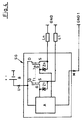
- FIG. 1 shows a control unit (SG) with a Protective device designed according to the invention (SE).
- SE Protective device designed according to the invention
- all diodes (D1, Dn) are with each other and with connected to the ground connection (M) of the control unit.
- the one formed by this arrangement of diodes (D1, Dn) Protective device (SE) provides in the event of an interruption the control unit ground (GND1) of the control circuit (A) one Auxiliary mass available.
- the control circuit (A) can each load (L1, Ln) by acting on the control electrode (G) of the assigned Load switch (T1, Tn) with a high potential with the Connect the positive pole (+) of the voltage source or the Load switch (T1, Tn) by applying the Lock control electrode with a low potential and switch off the assigned load (L1, Ln).
- the ground potential present at the ground connection (M) drops however, in the event that the drive circuit all Controls loads simultaneously. If the function of the Control unit a simultaneous control of all loads enables, a for the control circuit Voltage monitoring device (SÜ) provided.
- This Voltage monitoring device (SÜ) monitors the on the Control circuit (A) applied operating voltage and thus the potential present at the ground connection of the control unit.
- the control unit mass (GND1) is interrupted, all Loads (L1, Ln) switched on at the same time, the Voltage at the voltage monitoring device (SÜ).
- the Control circuit (A) for example, by a Microprocessor can be realized based on the Decrease in voltage that an interruption of the Control unit ground is present and will be the further control prevent loads (L1, Ln).
- the so expanded Protective device also works in the event that the Mass interruption occurs at a time when all Loads are switched on at the same time.
- FIG 2 shows a similar circuit, instead of discrete trained load switches integrated load switches (IC1, ICn) (so-called high-side driver).
- IC1, ICn integrated load switches
- Such Integrated load switches (IC1, ICn) enable one simplified control, which means that for control used control circuit a simpler structure can have. In the basic mode of operation this control unit does not differ from that in the Figure 1 shown.
- FIG. 1 Figure 3 shows the control unit Protective device (SE) a PTC resistor (PTC), which with the diodes (D1, Dn) connected on the anode side connected in series is.
- SE control unit Protective device
- PTC PTC resistor
- the PTC resistor acts (PTC) in this case as a current limiting resistor that current flowing through the PTC resistor (PTC) heats it and thereby increases its resistance. This will the current through PTC resistor, diodes and load switch on a safe for the load switch (T1, Tn, IC1, ICn) Dimension reduced.
- the voltage monitoring device SÜ
- the control circuit A) the potential at Connection point between the PTC resistor (PTC) and the Diodes (D1, Dn) monitored. If the voltage falls below (U PTC) a predetermined value, so the Control circuit a further control of the load switch.
- the control circuit not only recognizes, as with a circuit according to Figures 1 and 2 an interrupted Control unit ground line (GND1), but also an inflated one Load of the auxiliary mass as well as in regular operation (the means without an interruption of the mass) an impermissibly high heating of the control unit.
- GND1 interrupted Control unit ground line
Description
Die Erfindung betrifft ein Steuergerät mit einer Schaltungsanordnung zum Schutz des Steuergerätes bei Unterbrechung der Steuergerätemasse, insbesondere in Kraftfahrzeugen, mit mindestens einem elektronischen Lastschalter, mit jeweils einer Last, die zwischen dem negativen Pol, einer Spannungsquelle und einer ersten Elektrode des jeweiligen Lastschalters angeordnet ist und über eine zweite Elektrode des Lastschalters mit dem positiven Pol der Spannungsquelle verbindbar ist, und mit einer Ansteuerschaltung, die eine Steuerelektrode des jeweiligen Lastschalters zur Betätigung des Lastschalters ansteuert.The invention relates to a control device with a circuit arrangement for Protection of the control unit if the control unit mass is interrupted, especially in motor vehicles, with at least one electronic Load switch, each with a load that is between the negative pole, one Voltage source and a first electrode of the respective load switch is arranged and with a second electrode of the circuit breaker positive pole of the voltage source is connectable, and with a Control circuit that a control electrode of the respective load switch Actuation of the load switch.
Ein solches Steuergerät ist aus der europäischen Patentanmeldung 0 519 156 bekannt. In dieser Schrift ist bereits ein Problem beschrieben, welches sich daraus ergibt, dass das Steuergerät und damit die Lastschalter mit einer anderen Masseleitung verbunden sind als die angesteuerten Lasten. Eine solche Anordnung ist insbesondere in Kraftfahrzeugen üblich, da hierdurch zumindest eine Masseleitung zwischen dem Steuergerät und der mindestens einen angesteuerten Last eingespart werden kann.Such a control device is from European patent application 0 519 156 known. In this document a problem is already described, which is this means that the control unit and thus the load switch with a are connected to a different ground line than the controlled loads. A such an arrangement is particularly common in motor vehicles because of this at least one ground line between the control unit and the at least one a controlled load can be saved.
Kommt es nun zu einer Unterbrechung in der zum Steuergerät führenden Masseleitung, so kann das Potential an der Steuerelektrode des elektronischen Lastschalters soweit ansteigen, dass dieser teilweise durchschaltet. Hierdurch entsteht am Lastschalter eine relativ hohe Verlustleitung, die zur Zerstörung des Lastschalters führen kann.Now there is an interruption in the leading to the control unit Ground line, so the potential at the control electrode of the electronic Increase the load switch so that it partially switches through. hereby a relatively high loss line arises at the load switch, which leads to destruction of the circuit breaker.
Um dieses zu vermeiden, wird für das Steuergerät nach der EPA 0 519 156 folgende Schutzmaßnahme vorgesehen: To avoid this, the control unit according to EPA 0 519 156 the following protective measure is provided:
Wird die Masseleitung des Steuergerätes unterbrochen, etwa durch Abziehen oder Abgleiten eines Anschlusssteckers, so wird dem Steuergerät mittels einer als Diode ausgebildeten Schutzeinrichtung intern eine Hilfsmasse zur Verfügung gestellt. Diese Hilfsmasse entsteht dadurch, dass im ausgeschalteten Zustand des mindestens einen Lastschalters der Masseanschluß des Steuergerätes über mindestens eine Last und die als Diode ausgebildete Schutzeinrichtung mit der Systemmasse, mit der auch die Lasten in Verbindung stehen, verbunden wird.If the ground wire of the control unit is interrupted, for example by pulling it off or sliding of a connector, the control unit by means of a an auxiliary ground designed as a diode protective device Provided. This auxiliary mass arises from the fact that switched off state of the at least one load switch Earth connection of the control unit via at least one load and as Diode protective device with the system mass, with which the Loads are connected, is connected.
Nachteilig an dem vorbekannten Steuergerät ist, dass es nicht gegen Verpolung geschützt ist. Werden nämlich der Masseanschluß und der Spannnungsversorgungsanschluß des Steuergerätes beim Anschluß an die Spannungsquelle vertauscht, so fließt durch die Dioden der Schutzeinrichtung und die Lastschalter ein hoher Strom, der zu einer Zerstörung der Lastschalter führen kann.A disadvantage of the known control device is that it is not against Reverse polarity is protected. Namely, the ground connection and the Power supply connection of the control unit when connecting to the If the voltage source is interchanged, it flows through the diodes of the protective device and the load switch a high current, which leads to destruction of the load switch can lead.
Es ist daher die Aufgabe der Erfindung, ein Steuergerät zu schaffen, bei dem der oder die Lastschalter bei einem Bruch der Masseleitung auf besonders einfache und kostengünstige Weise gegen Überlastung geschützt werden können und das zudem gegen eine Verpolung der Spannungsquelle geschützt ist.It is therefore the object of the invention to provide a control device in which the load switch or switches in the event of a break in the ground line particularly simple and inexpensive way to be protected against overload can and also protected against reverse polarity of the voltage source is.
Diese Aufgabe wird erfindungsgemäß dadurch gelöst, dass zwischen die Verbindungspunkte von Lastschaltern und Lasten und den Masseanschluß des Steuergerätes eine Schutzeinrichtung geschaltet ist, die aus einer Reihenschaltung, aus einer Diode je Verbindungspunkt und einem PTC-Widerstand besteht. This object is achieved in that between the Connection points of load switches and loads and the ground connection of the Control device is connected to a protective device, which consists of a Series connection, consisting of a diode per connection point and a PTC resistor consists.
Durch das Einfügen des PTC-Widerstandes kann somit das Steuergerät auf überraschend einfache Weise verpolsicher ausgeführt werden. Hierbei wird vorteilhafterweise auch bei mehreren zu schützenden Lastschaltern nur ein PTC-Widerstand benötigt. Ein besonderer Vorteil ist darin zu sehen, dass im regulären Betrieb des Steuergerätes (d.h. ohne Unterbrechung der Steuergerätemasse) der PTC-Widerstand die Temperatur des Steuergerätes überwachen kann.By inserting the PTC resistor, the control unit can open Surprisingly simple way to be protected against polarity reversal. Here will advantageously only one if there are several circuit breakers to be protected PTC resistor required. A particular advantage is the fact that in the regular operation of the control unit (i.e. without interrupting the Control unit ground) the PTC resistance the temperature of the control unit can monitor.
Weitere vorteilhafte Ausgestaltungen und Weiterbildungen gehen aus den Unteransprüchen hervor.Further advantageous refinements and developments go from the Sub-claims emerge.
So ist es vorteilhaft, wenn die Ansteuerschaltung eine Spannungsüberwachungseinrichtung aufweist, die ein an der Schutzeinrichtung vorliegendes Potential überwacht. Sofern vorgesehen ist, dass das Steuergerät alle Lasten gleichzeitig ansteuern kann, fällt in diesem Fall die Hilfsmasse am Masseanschluß des Steuergerätes fort.So it is advantageous if the control circuit Has voltage monitoring device, the one on the Protective device monitors existing potential. If provided that the control unit can control all loads at the same time If the auxiliary ground continues at the ground connection of the control unit.
Dieses wird durch die Spannungsüberwachungseinrichtung erkannt, worauf die Ansteuerschaltung die weitere Ansteuerung der Lastschalter einstellt. Eine solche in die Ansteuerschaltung integrierte Spannungsüberwachung verursacht dabei nur einen unwesentlichen Kostenanteil der Ansteuerschaltung. This is recognized by the voltage monitoring device, whereupon the Control circuit sets the further control of the load switch. A caused such voltage monitoring integrated in the control circuit only an insignificant share of the cost of the control circuit.
Es zeigen:
Figur 1- ein erstes Ausführungsbeispiel eines erfindungsgemäßen Steuergerätes mit diskret ausgeführten Lastschaltern;
- Figur 2
- eine zweite Ausführungsform eines erfindungsgemäßen Steuergerätes mit integrierten Lastschaltern;
- Figur 3
- eine dritte Ausführungsform eines erfindungsgemäßen Steuergerätes mit einer abgewandelt ausgeführten Schutzeinrichtung;
- Figur 4
- ein Steuergerät nach dem Stand der Technik.
- Figure 1
- a first embodiment of a control device according to the invention with discretely designed load switches;
- Figure 2
- a second embodiment of a control device according to the invention with integrated load switches;
- Figure 3
- a third embodiment of a control device according to the invention with a modified protective device;
- Figure 4
- a control device according to the prior art.
Anhand der Figur 4 soll zunächst die der Erfindung zugrundeliegende Problematik näher ausgeführt werden.4, that of the invention is intended first underlying problems are explained in more detail.
Zu dem in der Figur 4 dargestellten Steuergerät (SG) gehören ein oder mehrere Lastschalter (allgemein n Stück) von denen in der Figur 4 zwei Lastschalter (T1, Tn) beispielhaft dargestellt sind. Die Lastschalter sind hier als Leistungs-MOS-Feldeffekttransistoren ausgeführt. Als übliche Maßnahme zum Schutz vor Überspannung ist parallel zur Source-Gate-Strecke jedes Lastschalters (T1, Tn) eine Zener-Diode (Z1, Zn) geschaltet.Belong to the control unit (SG) shown in FIG. 4 one or more load switches (generally n pieces) of which in Figure 4 two load switches (T1, Tn) as an example are shown. The load switches are here as Power MOS field effect transistors executed. As usual Measure to protect against overvoltage is parallel to Source-gate distance of each load switch (T1, Tn) one Zener diode (Z1, Zn) switched.
Das Steuergerät (SG) kann über die Lastschalter (T1, Tn) Lasten (L1, Ln) mit dem positiven Pol (+) einer Spannungsquelle (B) verbinden. Die außerhalb des Steuergerätes angeordneten Lasten (L1, Ln) stehen mit der Systemmasse (GND) (beispielsweise in einem Kraftfahrzeug der Kraftfahrzeugkarosserie) in Verbindung. Zur Ansteuerung der Lastschalter (T1, Tn) besitzt das Steuergerät eine Ansteuerschaltung (A). Zum Einschalten eines Lastschalters (T1, Tn) beaufschlagt die Ansteuerschaltung (A) die Gate-Elektrode (G) des Lastschalters (T1, Tn) mit einem positiven Potential und zum Sperren des Lastschalters (T1, Tn) entsprechend mit einem Potential, welches in der Nähe des Massepotentials liegt.The control unit (SG) can be operated via the load switches (T1, Tn) Loads (L1, Ln) with the positive pole (+) one Connect voltage source (B). The outside of the Control unit arranged loads (L1, Ln) stand with the System mass (GND) (for example in a motor vehicle Motor vehicle body) in connection. To control the The control unit has a load switch (T1, Tn) Control circuit (A). For switching on a load switch (T1, Tn) acts on the control circuit (A) Gate electrode (G) of the load switch (T1, Tn) with a positive potential and to lock the load switch (T1, Tn) accordingly with a potential which is close to the Ground potential.
Hierzu ist die Ansteuerschaltung (A) sowohl mit dem positiven Pol (+) der Spannungsquelle (B) als auch über den Masseanschluß (M ) des Steuergerätes (SG) mit einer eigenen Masseleitung (im folgenden als Steuergerätemasse GND1 bezeichnet) verbunden.For this purpose, the control circuit (A) with both the positive Pol (+) of the voltage source (B) as well as over the Ground connection (M) of the control unit (SG) with its own Ground line (in the following as control unit ground GND1 designated) connected.
Erfolgt durch einen Fehler (Kabelbruch, abgleitender Anschlußstecker oder ähnliches) eine Unterbrechung der Steuergerätemasse (in der Zeichnung angedeutet durch ein punktiertes Linienstück), so kann die Ansteuerschaltung (A) den Steuerelektroden (G) der Lastschalter (T1, Tn) nicht das zum Sperren nötige Potential zur Verfügung stellen.Is caused by an error (cable break, sliding Connector or the like) an interruption of the Control unit mass (indicated in the drawing by a dotted line piece), the control circuit (A) the control electrodes (G) of the load switches (T1, Tn) not that provide the potential necessary for blocking.
Über die Ansteuerschaltung (A) gelangt nun ein mehr oder weniger hohes Potential an die Steuerelektroden (G) der Lastschalter, welches zum Einschalten der Lasten führt.Via the control circuit (A) you can get more or less high potential to the control electrodes (G) Load switch, which leads to the switching on of the loads.
Schlimmer noch ist es, wenn es bei nicht ausreichend hohem Potential an der Steuerelektrode (G) der Lastschalter (T1, Tn) zu einem undefinierten Schaltzustand, etwa einem teilweisen Durchschalten der Lastschalter kommt, bei welchen eine hohe Verlustleistung an den Lastschaltern auftritt und zu deren Zerstörung führt.It is worse if it is not high enough Potential at the control electrode (G) of the load switch (T1, Tn) to an undefined switching state, such as one partial switching of the load switch comes, at which a high power loss occurs at the load switches and leads to their destruction.
Es sind Schutzschaltungen für solche Steuergeräte bekannt, bei denen jedem Lastschalter ein weiterer (in der Figur nicht dargestellter) Transistor zugeordnet wird, welcher bei Unterbrechung der Steuergerätemasse die Gate-Elektrode (G) und die Source-Elektrode (S) jedes MOS-Feldeffekttransistors kurzschließt und so den Lastschalter sperrt.Protective circuits for such control devices are known where each load switch has another (not in the figure shown) transistor is assigned, which at Interruption of the control unit mass of the gate electrode (G) and the source electrode (S) of each MOS field effect transistor shorts and thus locks the load switch.
Besonders bei Steuergeräten mit einer größeren Anzahl von Lastschaltern stellen diese zusätzlich benötigten Transistoren einen erheblichen Kostenfaktor dar. Especially for control units with a larger number of Load switches provide these additionally required Transistors represent a significant cost factor.
Weitaus kostengünstiger ist demgegenüber die erfindungsgemäße Lösung, die in drei Ausführungsbeispielen in Figuren 1 bis 3 dargestellt ist.In contrast, the inventive method is far less expensive Solution in three exemplary embodiments in FIGS. 1 to 3 is shown.
Die Figur 1 zeigt ein Steuergerät (SG) mit einer erfindungsgemäß ausgebildeten Schutzeinrichtung (SE). Hierbei ist jedem zu schützenden Lastschalter (T1, Tn) eine Diode (D1, Dn) zugeordnet, deren Kathode mit dem Verbindungspunkt (V1, Vn) von Lastschalter (T1, Tn) und Last (L1, Ln) verbunden ist.1 shows a control unit (SG) with a Protective device designed according to the invention (SE). in this connection Every load switch (T1, Tn) to be protected is a diode (D1, Dn), whose cathode is connected to the connection point (V1, Vn) of load switch (T1, Tn) and load (L1, Ln) connected is.
Anodenseitig sind alle Dioden (D1, Dn) miteinander und mit dem Masseanschluß (M) des Steuergerätes verbunden.On the anode side, all diodes (D1, Dn) are with each other and with connected to the ground connection (M) of the control unit.
Die durch diese Anordnung von Dioden (D1, Dn) ausgebildete Schutzeinrichtung (SE) stellt im Falle einer Unterbrechung der Steuergerätemasse (GND1) der Ansteuerschaltung (A) eine Hilfsmasse zur Verfügung.The one formed by this arrangement of diodes (D1, Dn) Protective device (SE) provides in the event of an interruption the control unit ground (GND1) of the control circuit (A) one Auxiliary mass available.
Die Funktionsweise eines Steuergerätes mit einer erfindungsgemäßen Schutzeinrichtung (SE) soll im folgenden anhand der Figur 1 näher erläutert werden:How a control unit works with a protective device according to the invention (SE) is intended in the following are explained in more detail with reference to FIG. 1:
Die Ansteuerschaltung (A) kann jede Last (L1, Ln) jeweils durch Beaufschlagung der Steuerelektrode (G) des zugeordneten Lastschalters (T1, Tn) mit einem hohen Potential mit dem Pluspol (+) der Spannungsquelle verbinden oder die Lastschalter (T1, Tn) durch Beaufschlagung der Steuerelektrode mit einem niedrigen Potential sperren und damit die zugeordnete Last (L1, Ln) abschalten.The control circuit (A) can each load (L1, Ln) by acting on the control electrode (G) of the assigned Load switch (T1, Tn) with a high potential with the Connect the positive pole (+) of the voltage source or the Load switch (T1, Tn) by applying the Lock control electrode with a low potential and switch off the assigned load (L1, Ln).
Fällt nun durch eine Unterbrechung der Steuergerätemasse (GND1) das Massepotential am Masseanschluß (M) des Steuergerätes fort und sei angenommen, daß zumindest eine der Lasten nicht eingeschaltet ist, so erhält der Masseanschluß (M) des Steuergerätes über die nicht eingeschaltete Last (L1, Ln) und die zugehörige Diode (D1, Dn) Massepotential von der Systemmasse (GND) zugeführt und kann seine Funktion fortsetzen.Now falls due to an interruption in the control unit mass (GND1) the ground potential at the ground terminal (M) of the Control unit continues and assume that at least one of the Loads are not switched on, the ground connection is given (M) of the control unit via the load that is not switched on (L1, Ln) and the associated diode (D1, Dn) ground potential from the System mass (GND) fed and can function continue.
Das am Masseanschluß (M) vorliegende Massepotential fällt allerdings in dem Fall weg, daß die Ansteuerschaltung alle Lasten gleichzeitig ansteuert. Sofern die Funktion des Steuergerätes eine gleichzeitige Ansteuerung aller Lasten ermöglicht, wird für die Ansteuerschaltung eine Spannungsüberwachungseinrichtung (SÜ) vorgesehen. Diese Spannungsüberwachungseinrichtung (SÜ) überwacht die an der Ansteuerschaltung (A) anliegende Betriebsspannung und damit das am Masseanschluß des Steuergerätes anliegende Potential. Werden nun bei unterbrochener Steuergerätemasse (GND1) alle Lasten (L1, Ln) gleichzeitig eingeschaltet, sinkt die Spannung an der Spannungsüberwachungseinrichtung (SÜ) ab. Die Ansteuerschaltung (A), die beispielsweise durch einen Mikroprozessor realisiert sein kann, erkennt aufgrund des Absinkens der Spannung, daß eine Unterbrechung der Steuergerätemasse vorliegt und wird die weitere Ansteuerung der Lasten (L1, Ln) verhindern. Die so erweitere Schutzeinrichtung funktioniert auch in dem Fall, daß die Masseunterbrechung zu einem Zeitpunkt auftritt, an dem alle Lasten gleichzeitig eingeschaltet sind.The ground potential present at the ground connection (M) drops however, in the event that the drive circuit all Controls loads simultaneously. If the function of the Control unit a simultaneous control of all loads enables, a for the control circuit Voltage monitoring device (SÜ) provided. This Voltage monitoring device (SÜ) monitors the on the Control circuit (A) applied operating voltage and thus the potential present at the ground connection of the control unit. Now if the control unit mass (GND1) is interrupted, all Loads (L1, Ln) switched on at the same time, the Voltage at the voltage monitoring device (SÜ). The Control circuit (A), for example, by a Microprocessor can be realized based on the Decrease in voltage that an interruption of the Control unit ground is present and will be the further control prevent loads (L1, Ln). The so expanded Protective device also works in the event that the Mass interruption occurs at a time when all Loads are switched on at the same time.
Figur 2 zeigt eine gleichartige Schaltung, die statt diskret ausgebildeten Lastschaltern integrierte Lastschalter (IC1, ICn) (sogenannte High-Side-Treiber) aufweist. Solche integrierten Lastschalter (IC1, ICn) ermöglichen eine vereinfachte Ansteuerung, wodurch die zur Ansteuerung verwendete Ansteuerschaltung einen einfacheren Aufbau aufweisen kann. In der grundsätzlichen Funktionsweise unterscheidet sich dieses Steuergerät nicht von dem in der Figur 1 dargestellten.Figure 2 shows a similar circuit, instead of discrete trained load switches integrated load switches (IC1, ICn) (so-called high-side driver). Such Integrated load switches (IC1, ICn) enable one simplified control, which means that for control used control circuit a simpler structure can have. In the basic mode of operation this control unit does not differ from that in the Figure 1 shown.
Eine vorteilhafte Variante des in der Figur 1 dargestellten Steuergerätes zeigt die Figur 3. Hier gehört zur Schutzeinrichtung (SE) ein PTC-Widerstand (PTC), der mit den anodenseitig verbundenen Dioden (D1, Dn) in Reihe geschaltet ist. Hierdurch wird das Steuergerät gegen Verpolung geschützt. Wird nämlich bei einer Schaltung nach Figur 1 oder Figur 2 versehentlich der positive Pol (+) der Spannungsquelle (B) mit dem Masseanschluß (M) des Steuergerätes und der negative Pol (-) der Spannungsquelle (B) mit dem Spannungsversorgungseingang (U+) des Steuergerätes verbunden, so fließt über die Reihenschaltung aus Dioden und Lastschalter jeweils ein sehr hoher Strom der zur Zerstörung der Lastschalter (T1, Tn, IC1, ICn) führt.An advantageous variant of that shown in FIG. 1 Figure 3 shows the control unit Protective device (SE) a PTC resistor (PTC), which with the diodes (D1, Dn) connected on the anode side connected in series is. As a result, the control unit prevents reverse polarity protected. Is namely in a circuit according to Figure 1 or Figure 2 accidentally the positive pole (+) of the Voltage source (B) with the ground connection (M) of the Control unit and the negative pole (-) of the voltage source (B) with the voltage supply input (U +) of the Control unit connected, then flows through the series connection from diodes and load switches each a very high current leads to the destruction of the load switches (T1, Tn, IC1, ICn).
Bei der Schaltung gemäß Figur 3 wirkt der PTC-Widerstand (PTC) in diesem Fall als strombegrenzender Widerstand, der durch den PTC-Widerstand (PTC) fließende Strom erwärmt diesen und vergrößert dadurch noch seinen Widerstand. Hierdurch wird der Strom durch PTC-Widerstand, Dioden und Lastschalter auf ein für die Lastschalter (T1, Tn, IC1, ICn) ungefährliches Maß reduziert.In the circuit according to Figure 3, the PTC resistor acts (PTC) in this case as a current limiting resistor that current flowing through the PTC resistor (PTC) heats it and thereby increases its resistance. This will the current through PTC resistor, diodes and load switch on a safe for the load switch (T1, Tn, IC1, ICn) Dimension reduced.
Vorteilhaft ist, wenn die Spannungsüberwachungseinrichtung (SÜ) der Ansteuerschaltung (A) das Potential am Verbindungspunkt zwischen dem PTC-Widerstand (PTC) und den Dioden (D1, Dn) überwacht. Unterschreitet die Spannung (U PTC) einen vorgegebenen Wert, so verhindert die Ansteuerschaltung eine weitere Ansteuerung der Lastschalter. Hierbei erkennt die Ansteuerschaltung nicht nur, wie bei einer Schaltung gemäß den Figuren 1 und 2 eine unterbrochene Steuergerätemasseleitung (GND1), sondern auch eine überhöhte Belastung der Hilfsmasse sowie im regulären Betrieb (das heißt ohne Masseunterbrechung) eine unzulässig hohe Erwärmung des Steuergerätes.It is advantageous if the voltage monitoring device (SÜ) the control circuit (A) the potential at Connection point between the PTC resistor (PTC) and the Diodes (D1, Dn) monitored. If the voltage falls below (U PTC) a predetermined value, so the Control circuit a further control of the load switch. Here, the control circuit not only recognizes, as with a circuit according to Figures 1 and 2 an interrupted Control unit ground line (GND1), but also an inflated one Load of the auxiliary mass as well as in regular operation (the means without an interruption of the mass) an impermissibly high heating of the control unit.
Claims (6)
- Controller (SG) with a circuit arrangement for its protection when the controller earth (GND1) is interrupted, particularly in motor vehicles, with at least one electronic power circuit breaker (T1, Tn, IC1, ICn) with a load (L1, Ln) which is arranged between the negative pole (-) of a voltage source (B) and the first electrode (S) of the power circuit breaker (T1, Tn, IC1, ICn) and is connectable via a second electrode (D) of the power circuit breaker (T1, Tn, IC1, ICn) to the positive pole (+) of the voltage source (B), and with a driver circuit (A) which drives a control electrode (G) of the power circuit breaker (T1, Tn, IC1, ICn) to actuate the power circuit breaker (T1, Tn, IC1, ICn), characterized in that a protective device (SE) consisting of a series connection of a diode (D1, Dn) for each connection point (V1, Vn) and a positive temperature coefficient resistor (PTC) is connected between the connection points (V1, Vn) of power circuit breakers (T1, Tn, IC1, ICn) and loads (L1, Ln) and the earth connection (M) of the controller (SG).
- Controller according to Claim 1, characterized in that the at least one electronic power circuit breaker is configured as an n-channel power metal-oxide-semiconductor field-effect transistor.
- Controller according to Claim 1, characterized in that the at least one electronic power circuit breaker is configured as an integrated high-side driver module (IC1, ICn).
- Controller according to Claim 1, characterized in that the controller (SG) has a plurality of power circuit breakers (T1, Tn, IC1, ICn) each for driving a load (L1, Ln), and in that each connection point (V1, Vn) between load (L1, Ln) and power circuit breaker (T1, Tn, IC1, ICn) is connected to the cathode terminal of a diode (D1, Dn) and in that the positive temperature coefficient resistor (PTC) is connected between the connected anode terminals of the diodes (D1, Dn) and the earth connection (M) of the controller (SG).
- Controller according to Claim 1, characterized in that the driver circuit (A) [is provided with] a voltage monitoring device (SÜ) [which] monitors the potential (UPTC).
- Controller according to any one of the abovementioned claims, characterized in that the voltage monitoring device (SÜ) monitors the potential (UPTC) at the anode terminals of the diodes (D1, Dn) and in that the driver circuit ceases driving all power circuit breakers (T1, Tn, IC1, ICn) when the difference between the monitored potential (UPTC) and the potential of the positive pole (+) of the voltage source (B) falls below a specified value.
Applications Claiming Priority (2)
| Application Number | Priority Date | Filing Date | Title |
|---|---|---|---|
| DE4428115A DE4428115C2 (en) | 1994-08-09 | 1994-08-09 | Control unit with a circuit arrangement for protecting the control unit when the control unit mass is interrupted |
| DE4428115 | 1994-08-09 |
Publications (3)
| Publication Number | Publication Date |
|---|---|
| EP0696849A2 EP0696849A2 (en) | 1996-02-14 |
| EP0696849A3 EP0696849A3 (en) | 1997-09-17 |
| EP0696849B1 true EP0696849B1 (en) | 2003-12-03 |
Family
ID=6525234
Family Applications (1)
| Application Number | Title | Priority Date | Filing Date |
|---|---|---|---|
| EP95111388A Expired - Lifetime EP0696849B1 (en) | 1994-08-09 | 1995-07-20 | Control apparatus with a circuit arrangement for its protection when the earth connection is interrupted |
Country Status (3)
| Country | Link |
|---|---|
| EP (1) | EP0696849B1 (en) |
| DE (2) | DE4428115C2 (en) |
| ES (1) | ES2211888T3 (en) |
Families Citing this family (7)
| Publication number | Priority date | Publication date | Assignee | Title |
|---|---|---|---|---|
| DE10002537A1 (en) * | 2000-01-21 | 2001-07-26 | Volkswagen Ag | Incorrect ground connection detection method for electrical device mounted in vehicles, involves comparing voltage measured by detection circuit with reference value based on which ground fault is detected |
| DE10356089B4 (en) * | 2003-12-01 | 2005-11-03 | Siemens Ag | Circuit arrangement and method for controlling an inductive load |
| JP4473294B2 (en) * | 2007-09-05 | 2010-06-02 | 矢崎総業株式会社 | Power control device |
| DE102009034825A1 (en) * | 2009-07-27 | 2011-02-03 | Kromberg & Schubert Gmbh & Co. Kg | Switching device for use in electrical system of e.g. aircraft for connecting and interrupting conduction path to electrical consumer load, has switching element connecting load with power supply unit or separating load from supply unit |
| CN103582824B (en) | 2011-05-27 | 2016-08-17 | 飞思卡尔半导体公司 | Ground connection is lost supervisory circuit and includes its integrated circuit |
| DE102012214906A1 (en) | 2012-08-22 | 2014-02-27 | Automotive Lighting Reutlingen Gmbh | Control unit for electrical load |
| FR3011638B1 (en) * | 2013-10-04 | 2017-05-26 | Continental Automotive France | DEVICE FOR DIAGNOSING THE LOSS OF A CONNECTION BETWEEN AN ELECTRONIC CONTROL MODULE AND A MASS |
Family Cites Families (7)
| Publication number | Priority date | Publication date | Assignee | Title |
|---|---|---|---|---|
| DE2331708A1 (en) * | 1973-06-22 | 1975-01-16 | Gerd Rudi Willi Ebinger | Overload protection circuit with PTC resistor in series with load - uses sharp step in resistor temperature resistance characteristics |
| DE3128303A1 (en) * | 1981-07-17 | 1983-02-03 | Brown, Boveri & Cie Ag, 6800 Mannheim | Device for protecting electric motors against overheating |
| US4691129A (en) * | 1986-03-19 | 1987-09-01 | Siemens Aktiengesellschaft | Drive circuit for a power MOSFET with source-side load |
| US4725912A (en) * | 1986-06-16 | 1988-02-16 | Motorola Inc. | Power MOS loss of ground protection |
| US4945445A (en) * | 1988-09-29 | 1990-07-31 | Gentron Corporation | Current sense circuit |
| GB2237462A (en) * | 1989-10-23 | 1991-05-01 | Philips Nv | Overload protection drive circuit for a power transistor |
| IT1249525B (en) * | 1991-02-18 | 1995-02-23 | Sgs Thomson Microelectronics | MASS LOSS PROTECTION DEVICE ESPECIALLY FOR MOS INTEGRATED CIRCUITS |
-
1994
- 1994-08-09 DE DE4428115A patent/DE4428115C2/en not_active Expired - Fee Related
-
1995
- 1995-07-20 DE DE59510838T patent/DE59510838D1/en not_active Expired - Lifetime
- 1995-07-20 EP EP95111388A patent/EP0696849B1/en not_active Expired - Lifetime
- 1995-07-20 ES ES95111388T patent/ES2211888T3/en not_active Expired - Lifetime
Also Published As
| Publication number | Publication date |
|---|---|
| DE4428115C2 (en) | 1997-10-16 |
| EP0696849A3 (en) | 1997-09-17 |
| ES2211888T3 (en) | 2004-07-16 |
| DE4428115A1 (en) | 1996-02-15 |
| EP0696849A2 (en) | 1996-02-14 |
| DE59510838D1 (en) | 2004-01-15 |
Similar Documents
| Publication | Publication Date | Title |
|---|---|---|
| DE19614354C2 (en) | Control circuit for a MOS gate-controlled power semiconductor circuit | |
| EP3583670B1 (en) | Electronic circuit-breaker for a load that can be connected to a low voltage dc-voltage network | |
| DE102006030448B4 (en) | Safe output circuit with a single-channel peripheral connection for the output of a bus participant | |
| DE102021122687A1 (en) | Arrangement and method for discharging an intermediate circuit capacitor | |
| EP0696849B1 (en) | Control apparatus with a circuit arrangement for its protection when the earth connection is interrupted | |
| DE102015207783B4 (en) | Overvoltage protected electronic control unit | |
| DE10232941B4 (en) | Vehicle electrical system with a sensor protection circuit | |
| DE19838109B4 (en) | Control circuit for inductive loads | |
| DE3834867C1 (en) | Circuit arrangement for the parallel connection of power supply devices | |
| DE202016008824U1 (en) | Reversible electronic circuit breaker terminal | |
| DE10349629B4 (en) | Electronic circuit | |
| EP1306680B1 (en) | Circuit for load current monitoring | |
| EP1193824A2 (en) | Reverse battery protection circuit | |
| EP0581110B1 (en) | Circuit arrangement for reducing overvoltages on transistors | |
| DE102004041466B4 (en) | Electromotive actuator with control unit for intermediate position and control method | |
| DE10243571B4 (en) | Circuit arrangement for short circuiting a MOSFET switch | |
| DE10253980B4 (en) | Device for limiting the inrush current | |
| DE19936857A1 (en) | Protection circuit for an electrical switching element | |
| DE10349282A1 (en) | Cross-polarity and overvoltage protection for d.c. circuit arrangement, e.g. for 5 volt sensors, has control arrangement that switches on switch in normal operation to connect first and second connectors of switch together | |
| EP0822661A2 (en) | Drive circuit for a field effect controlled power semiconductor device | |
| DE102014008906A1 (en) | Electronic relay | |
| DE4137452A1 (en) | POLE PROTECTION ARRANGEMENT FOR POWER AMPLIFIER FIELD EFFECT TRANSISTORS | |
| DE10137499C1 (en) | Switch element monitoring circuit evaluates measured voltage drop across monitored switch element in series with inductance | |
| DE102020202842A1 (en) | Driver circuit for a low-inductance power module and a low-inductance power module with increased short-circuit strength | |
| WO2012123276A1 (en) | Device for deactivating a power transistor |
Legal Events
| Date | Code | Title | Description |
|---|---|---|---|
| PUAI | Public reference made under article 153(3) epc to a published international application that has entered the european phase |
Free format text: ORIGINAL CODE: 0009012 |
|
| AK | Designated contracting states |
Kind code of ref document: A2 Designated state(s): DE ES FR GB IT SE |
|
| PUAL | Search report despatched |
Free format text: ORIGINAL CODE: 0009013 |
|
| RHK1 | Main classification (correction) |
Ipc: H03K 17/082 |
|
| AK | Designated contracting states |
Kind code of ref document: A3 Designated state(s): DE ES FR GB IT SE |
|
| 17P | Request for examination filed |
Effective date: 19971204 |
|
| 17Q | First examination report despatched |
Effective date: 20020422 |
|
| GRAH | Despatch of communication of intention to grant a patent |
Free format text: ORIGINAL CODE: EPIDOS IGRA |
|
| GRAS | Grant fee paid |
Free format text: ORIGINAL CODE: EPIDOSNIGR3 |
|
| GRAA | (expected) grant |
Free format text: ORIGINAL CODE: 0009210 |
|
| AK | Designated contracting states |
Kind code of ref document: B1 Designated state(s): DE ES FR GB IT SE |
|
| REG | Reference to a national code |
Ref country code: GB Ref legal event code: FG4D Free format text: NOT ENGLISH |
|
| REG | Reference to a national code |
Ref country code: SE Ref legal event code: TRGR |
|
| REF | Corresponds to: |
Ref document number: 59510838 Country of ref document: DE Date of ref document: 20040115 Kind code of ref document: P |
|
| GBT | Gb: translation of ep patent filed (gb section 77(6)(a)/1977) |
Effective date: 20040128 |
|
| PGFP | Annual fee paid to national office [announced via postgrant information from national office to epo] |
Ref country code: SE Payment date: 20040706 Year of fee payment: 10 |
|
| PGFP | Annual fee paid to national office [announced via postgrant information from national office to epo] |
Ref country code: FR Payment date: 20040708 Year of fee payment: 10 |
|
| PGFP | Annual fee paid to national office [announced via postgrant information from national office to epo] |
Ref country code: GB Payment date: 20040714 Year of fee payment: 10 |
|
| REG | Reference to a national code |
Ref country code: ES Ref legal event code: FG2A Ref document number: 2211888 Country of ref document: ES Kind code of ref document: T3 |
|
| PGFP | Annual fee paid to national office [announced via postgrant information from national office to epo] |
Ref country code: ES Payment date: 20040719 Year of fee payment: 10 |
|
| ET | Fr: translation filed | ||
| PLBE | No opposition filed within time limit |
Free format text: ORIGINAL CODE: 0009261 |
|
| STAA | Information on the status of an ep patent application or granted ep patent |
Free format text: STATUS: NO OPPOSITION FILED WITHIN TIME LIMIT |
|
| 26N | No opposition filed |
Effective date: 20040906 |
|
| PG25 | Lapsed in a contracting state [announced via postgrant information from national office to epo] |
Ref country code: IT Free format text: LAPSE BECAUSE OF NON-PAYMENT OF DUE FEES;WARNING: LAPSES OF ITALIAN PATENTS WITH EFFECTIVE DATE BEFORE 2007 MAY HAVE OCCURRED AT ANY TIME BEFORE 2007. THE CORRECT EFFECTIVE DATE MAY BE DIFFERENT FROM THE ONE RECORDED. Effective date: 20050720 Ref country code: GB Free format text: LAPSE BECAUSE OF NON-PAYMENT OF DUE FEES Effective date: 20050720 |
|
| PG25 | Lapsed in a contracting state [announced via postgrant information from national office to epo] |
Ref country code: SE Free format text: LAPSE BECAUSE OF NON-PAYMENT OF DUE FEES Effective date: 20050721 Ref country code: ES Free format text: LAPSE BECAUSE OF NON-PAYMENT OF DUE FEES Effective date: 20050721 |
|
| EUG | Se: european patent has lapsed | ||
| GBPC | Gb: european patent ceased through non-payment of renewal fee |
Effective date: 20050720 |
|
| PG25 | Lapsed in a contracting state [announced via postgrant information from national office to epo] |
Ref country code: FR Free format text: LAPSE BECAUSE OF NON-PAYMENT OF DUE FEES Effective date: 20060331 |
|
| REG | Reference to a national code |
Ref country code: FR Ref legal event code: ST Effective date: 20060331 |
|
| REG | Reference to a national code |
Ref country code: ES Ref legal event code: FD2A Effective date: 20050721 |
|
| PGFP | Annual fee paid to national office [announced via postgrant information from national office to epo] |
Ref country code: DE Payment date: 20140716 Year of fee payment: 20 |
|
| REG | Reference to a national code |
Ref country code: DE Ref legal event code: R071 Ref document number: 59510838 Country of ref document: DE |