EP0696755B1 - Camera for film with a magnetic storage part - Google Patents
Camera for film with a magnetic storage part Download PDFInfo
- Publication number
- EP0696755B1 EP0696755B1 EP95112106A EP95112106A EP0696755B1 EP 0696755 B1 EP0696755 B1 EP 0696755B1 EP 95112106 A EP95112106 A EP 95112106A EP 95112106 A EP95112106 A EP 95112106A EP 0696755 B1 EP0696755 B1 EP 0696755B1
- Authority
- EP
- European Patent Office
- Prior art keywords
- film
- magnetic head
- head
- camera
- recording medium
- Prior art date
- Legal status (The legal status is an assumption and is not a legal conclusion. Google has not performed a legal analysis and makes no representation as to the accuracy of the status listed.)
- Expired - Lifetime
Links
Images


Classifications
-
- G—PHYSICS
- G03—PHOTOGRAPHY; CINEMATOGRAPHY; ANALOGOUS TECHNIQUES USING WAVES OTHER THAN OPTICAL WAVES; ELECTROGRAPHY; HOLOGRAPHY
- G03B—APPARATUS OR ARRANGEMENTS FOR TAKING PHOTOGRAPHS OR FOR PROJECTING OR VIEWING THEM; APPARATUS OR ARRANGEMENTS EMPLOYING ANALOGOUS TECHNIQUES USING WAVES OTHER THAN OPTICAL WAVES; ACCESSORIES THEREFOR
- G03B17/00—Details of cameras or camera bodies; Accessories therefor
- G03B17/24—Details of cameras or camera bodies; Accessories therefor with means for separately producing marks on the film, e.g. title, time of exposure
-
- G—PHYSICS
- G03—PHOTOGRAPHY; CINEMATOGRAPHY; ANALOGOUS TECHNIQUES USING WAVES OTHER THAN OPTICAL WAVES; ELECTROGRAPHY; HOLOGRAPHY
- G03B—APPARATUS OR ARRANGEMENTS FOR TAKING PHOTOGRAPHS OR FOR PROJECTING OR VIEWING THEM; APPARATUS OR ARRANGEMENTS EMPLOYING ANALOGOUS TECHNIQUES USING WAVES OTHER THAN OPTICAL WAVES; ACCESSORIES THEREFOR
- G03B2217/00—Details of cameras or camera bodies; Accessories therefor
- G03B2217/002—Details of arrangement of components in or on camera body
-
- G—PHYSICS
- G03—PHOTOGRAPHY; CINEMATOGRAPHY; ANALOGOUS TECHNIQUES USING WAVES OTHER THAN OPTICAL WAVES; ELECTROGRAPHY; HOLOGRAPHY
- G03B—APPARATUS OR ARRANGEMENTS FOR TAKING PHOTOGRAPHS OR FOR PROJECTING OR VIEWING THEM; APPARATUS OR ARRANGEMENTS EMPLOYING ANALOGOUS TECHNIQUES USING WAVES OTHER THAN OPTICAL WAVES; ACCESSORIES THEREFOR
- G03B2217/00—Details of cameras or camera bodies; Accessories therefor
- G03B2217/24—Details of cameras or camera bodies; Accessories therefor with means for separately producing marks on the film
- G03B2217/242—Details of the marking device
- G03B2217/244—Magnetic devices
Definitions
- This invention relates to an apparatus according to the preamble of claim 1, specifically to a camera to which a film having a magnetic storage part is applicable and which is provided with a magnetic head arranged to write or read information into or out of the magnetic storage part of the film.
- a camera of the kind having a magnetic head which is arranged to write or read information into or out of a magnetic storage part provided on a film and a holding member which is arranged to hold the magnetic head in such a way as to allow the magnetic head to swing on a support shaft extending in parallel with a transport direction of the film has been disclosed in JP-A-0 5-158136 which shows the generic prior art apparatus.
- the magnetic head is arranged to be capable of swinging on the support shaft of the holding member so as to follow any positional variation of the film taking place perpendicular to the film surface while the film is in process of transportation, and the magnetic head is arranged also to be located as far away as possible from the support shaft so that the magnetic head can be kept in constant contact with the film surface even when the magnetic head swings on the support shaft.
- the size of a magnetic head unit including the magnetic head and the holding member increases.
- the increase in size of the magnetic head unit leaves only a severely limited space above a pressure plate for arranging other mechanisms or elements and thus has presented a problem in that the size of the camera also inevitably increases.
- the head acts on the storage part of the image recording medium.
- a movable holding means is pivotable around an axis which is substantially parallel to a moving direction of the image recording medium.
- the holding means holds either the head or a pushing means which acts on the recording medium so that the head and the image recording medium are pressed against each other.
- JP-A-04 219 739 only teaches the use of means for detecting the perforation of a film without showing structural elements of arranging these means within the apparatus.
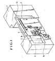
- Fig. 1 is an oblique view showing essential parts of a camera arranged according to this invention as a first embodiment thereof.
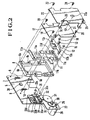
- Fig. 2 is an exploded oblique view showing a pressure plate unit of the first embodiment.
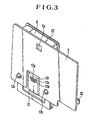
- Fig. 3 is an oblique view showing the pressure plate unit as viewed from a film surface.
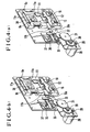
- Figs. 4(a) and 4(b) are oblique views showing different states of various members of the pressure plate unit obtained when the camera is writing or reading information and when the camera is performing an exposure action on the film.
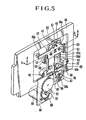
- Fig. 5 is an oblique view showing a pressure plate unit of a second embodiment of this invention.
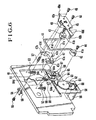
- Fig. 6 is an exploded oblique view showing the pressure plate unit of the second embodiment.
- Fig. 7 is a sectional view showing the second embodiment shown in Fig. 5.
- Fig. 8 is an oblique view showing a pressure plate unit of a third embodiment of this invention.
- Figs. 1 to 4 show a camera which is arranged as a first embodiment of this invention.
- Fig. 1 is an oblique view showing the arrangement of essential parts of the camera.
- a camera body 1 includes a cartridge chamber 1a and a spool chamber 1b.
- a film cartridge 2 which is usable by this embodiment contains therein a film 3 which is provided with a magnetic storage part and perforations 3a.
- a film takeup spool 4 of the camera is arranged to take up the film 3 with the spool 4 rotated through a transmission gear train by a motor which is not shown.
- a pressure plate 5 is secured to the camera body 1.
- Fig. 2 shows in an exploded oblique view the details of a pressure plate unit in a state of having been removed from the camera body 1.
- a slide holder 6 includes bearing parts 6a and 6b and spring hooking pegs 6c and 6d.
- Spring hooking pins 7 and 8 are planted in the pressure plate 5.
- Slide springs 9 and 10 are disposed respectively between the spring hooking peg 6c and the spring hooking pin 7 and between the spring hooking peg 6d and the spring hooking pin 8 and arranged to urge the slide holder 6 to move upward.
- a head holder 11 includes a rotation shaft 11a, an arm 11b, a spring receiving parts 11c and 11d and a cutout part 11e which is provided for disposing a perforation detecting means 38.
- the cutout part 11e is located in a direction approximately perpendicular to the moving direction of the film with respect to the magnetic head 12.
- the rotation shaft 11a extends in parallel with the film moving direction and is rotatably held by the bearing parts 6a and 6b of the slide holder 6.
- the magnetic head 12 is arranged to write and read information into and out of the magnetic storage part of the film 3.
- the magnetic head 12 is provided with a mounting base plate 12a and guide shafts 12b and 12c and is secured to the head holder 11 together with these parts by screws 13 and 14.
- Pushing springs 15 and 16 abut respectively on the spring receiving parts 11c and 11d of the head holder 11 at one end and are arranged to push the magnetic head 12 against the film surface 3 by causing the head holder 11 to swing on the rotation shaft 11a.
- a spring retainer 17 is secured to the slide holder 6 by screws 18, 19, 20, etc., and is arranged to receive the ends of the pushing springs 15 and 16.
- a slide guide shaft 21 is mounted on the spring retainer 17 and is arranged to be vertically slidable and rotatably guided within a slot 22a formed in a slide guide 22.
- the slide guide 22 is secured to the pressure plate 5 by screws 23 to 26.
- a motor base plate 27 is secured to the camera body 1.
- a motor 28 is secured to the motor base plate 27.
- a pinion gear 29 is secured to the output shaft of the motor 28.
- Double gears 30 and 31 are arranged after the pinion gear 29.
- An idle gear 32 is in mesh with the small gear (not shown) of the double gear 31.
- a slide lever 33 has a rack part 33e arranged to mesh with the idle gear 32 and includes slots 33a and 33b, a tapered part 33c and an arm 33d.
- Guide shafts 34 and 35 are secured to the pressure plate 5 and are arranged to hold the slide lever 33 in such a way as to allow the slide lever 33 to slide right and left as viewed on Fig. 2.
- a phase contact 36 is secured to the arm 33d of the slide lever 33.
- a phase circuit board 37 is secured to the pressure plate 5 and is arranged to detect, in conjunction with the phase contact 36, that the slide lever 33 has reached its left end position or its right end position.
- the perforation detecting means 38 is provided for detecting perforations 3a formed in the film 3 having a magnetic storage part.
- the perforation detecting means 38 is secured to the pressure plate 5 by means of an adhesive or a screw and is arranged to detect the perforations 3a through a detection window 5a provided in the pressure plate 5 as shown in Fig. 3. Further, a photo-reflector or a photo-interrupter or the like is employed as the perforation detecting means 38.
- Fig. 3 shows the pressure plate unit of Fig. 2 as viewed from the film surface.
- the magnetic head 12 is provided with a first track forming part 12d, a second track forming part 12e and a third track forming part 12f.
- Each of the track forming parts 12d, 12e and 12f has a gap part 12g which is formed in the direction of orthogonally intersecting the film transport direction.
- Each of the track forming parts 12d, 12e and 12f measures about 0.5 to 1 mm in width, while the gap part 12g measures several microns in width.
- the guide shafts 12b and 12c are arranged to be always kept in contact with the lower edge face of the film 3 by the slide springs 9 and 10 (see Fig. 2).
- the gap part 12g of the magnetic head 12 is swung on the rotation shaft 11a by the pushing springs 15 and 16 to be always elastically pushed toward the film surface. Therefore, even when the position of the film 3 fluctuates in the direction of its thickness in a stepped difference part between inner and outer rails of the camera body 1, the gap part 12g of the magnetic head 12 can be maintained in a state of closely contacting with the magnetic storage part of the film 3 without deviating from its position.
- Fig. 4(a) shows in an oblique view the state of each member obtained when the magnetic head 12 is writing or reading information into or out of the magnetic storage part of the film 3 while the film 3 is in process of transportation.
- the slide lever 33 is caused to begin to slide to the left through the transmission gears 30, 31 and 32 when the motor 28 is driven to rotate clockwise as viewed on the drawing.
- the motor 28 is stopped from being driven.
- the slide lever 33 since the slide lever 33 is in a position not to act in any manner on the head holder 11, the gap part 12g of the magnetic head 12 is pushed against the magnetic storage part of the film 3 by the elastic force of the pushing springs 15 and 16.
- Fig. 4(b) shows in an oblique view each of the members of the embodiment in a state obtained when the camera is performing an exposure action on the film 3.
- the motor 28 is driven to rotate counterclockwise as viewed on the drawing.
- the slide lever 33 is caused through the transmission gears 30, 31 and 32 to begin to slide to the right.
- the tapered part 33c of the slide lever 33 comes into a part under the arm 11b of the head holder 11 to push the arm 11b upward.
- the head holder 11 is swung on the rotation shaft 11a against the forces of the pushing springs 15 and 16.
- the magnetic head 12 is released from the state of closely contacting with the film 3 by this motion of the head holder 11.
- the magnetic head 12 is kept in this state while an exposure is in process, for the purpose of preventing any adverse effect of pushing the magnetic head 12 against the film 3 on the flatness of the film 3.
- the rotation shaft 11a of the head holder 11 must be arranged to be separate as much as possible from the magnetic head 12.
- the same advantageous effect can be attained by arranging, in the cutout part of the holding member for the magnetic head, some mechanical element such as a sprocket which rotates while engaging the perforations of the film.
- Figs. 5, 6 and 7 relate to a camera which is arranged as a second embodiment this invention.
- Fig. 5 is an oblique view showing a pressure plate unit of the camera.
- Fig. 6 is an exploded oblique view of the same pressure plate. Since the camera is arranged as a whole in the same manner as the first embodiment, other parts of the camera is omitted from illustrations.
- a magnetic head 40 is arranged to write or read information into or out of the magnetic storage part of a film 3 which is of the kind having a magnetic storage part.
- the magnetic head 40 is provided with a mounting base plate 40a and guide 41 to shafts 40b and 40c as shown in Fig. 7.
- the mounting base plate 40a is provided with spring hooking parts 40d and 40e for hooking springs which will be described later.
- a slide guide 41 is formed by bending a shaft of a circular sectional shape and consists of bent parts 41a and 41b which are in parallel with the film transport direction and guide parts 41c and 41d which orthogonally intersect the film transport direction and are in parallel to each other.
- Guide bearings 42 and 43 are arranged to engage the bent parts 41a and 41b of the slide guide 41 and to rotatably support the slide guide 41 to allow the slide guide 41 to swing on the bent parts 41a and 41b.
- Screws 44 and 45 fix the guide bearings 42 and 43 to the pressure plate 46.
- a holder 47 includes sliding parts 47a and 47b which have flat surfaces, R sliding parts 47c and 47d which are in an R-like shape and a push-up arm part 47e.
- the magnetic head 40 and the holder 47 are joined together by means of screws 48 and 49 with the guide parts 41c and 41d of the slide guide 41 sandwiched between them.
- Fig. 7 is a sectional view of the arrangement taken along a line A-A of Fig. 5.
- the guide parts 41c and 41d of the slide guide 41 are slidably sandwiched among the sliding parts 47a and 47b of the holder 47, the R sliding parts 47c and 47d and the mounting base plate 40a of the magnetic head 40.
- the magnetic head 40 is held in such a way as to be movable on a plane which is in parallel with the film surface and in the directions of rotation and the width of the film.
- Spring hooking pins 50 and 51 are planted in the pressure plate 46.
- Slide springs 52 and 53 are hooked and stretched respectively between the spring hooking part 40d of the magnetic head 40 and the spring hooking pin 50 and between the spring hooking part 40e of the magnetic head 40 and the spring hooking pin 51. These springs 52 and 53 are thus arranged to urge the magnetic head 40 to move downward as viewed on the drawing.
- An angle member 54 has a spring hooking pin 56 planted therein and is secured to the pressure plate 46 by a screw 55.
- a pushing spring 57 is arranged between the spring hooking pin 56 and the slide guide 41 to urge the slide guide 41 to swing on the bent parts 41a and 41b in such a way as to push the magnetic head 40 against the film surface.
- a motor base plate 58 is secured to the camera body 1.
- a motor 59 is secured to the motor base plate 58.
- a pinion gear 60 is secured to the output shaft of the motor 59.
- Double gears 61 and 62 There are provided double gears 61 and 62.
- An idle gear 63 is in mesh with the small gear part (not shown) of the double gear 62.
- a slide lever 64 includes a rack part 64a which is in mesh with the idle gear 63.
- the slide lever 64 is provided with slots 64b and 64c, a tapered part 64d and an arm part 64e.
- Guide shafts 65 and 66 are secured to the pressure plate 46 and engage respectively the slots 64b and 64c of the slide lever 64 to hold the slide lever 64 to be vertically slidable as viewed on the drawing.
- a phase contact 67 is secured to the arm part 64e of the slide lever 64.
- a phase circuit board 68 is secured to the camera body 1 and is arranged to detect, in conjunction with the phase contact 67, arrival of the slide lever 64 at its upper end position or its lower end position.
- Perforation detecting means 69 is arranged in the same manner as the means 38 of Fig. 2 to detect the perforations 3a provided in the film 3 and is secured to the pressure plate 46 by bonding, screws or some other suitable means.
- a space 70 encompassed with the guide parts 41c and 41d of the slide guide 41 is provided for disposing the perforation detecting means 69. The space 70 is located in a direction approximately perpendicular to the moving direction of the film 3 with respect to the magnetic head 40.
- Fig. 5 shows the state of each member obtained when the magnetic head 40 is operated to write or read information into or out of the magnetic storage part of the film 3 while the camera is in process of transporting the film 3.
- the slide lever 64 is located in a lower part as viewed on the drawing.
- the tapered part 64d of the slide lever 64 is not engaging the pushing-up arm part 47e of the holder 47. Therefore, the magnetic head 40 is in the state of being pushed against the film surface by the force of the pushing spring 57.
- the motor 59 In exposing .the film 3 to light, the motor 59 is driven to rotate clockwise.
- the slide lever 64 is caused to begin to slide upward through the transmission gears 61, 62 and 63.
- the tapered part 64d of the slide lever 64 then comes into a part under the pushing-up arm part 47e to push pushing-up arm part 47e upward.
- This upward motion causes the slide guide 41 to swing on the bent parts 41a and 41b against the pushing force of the pushing spring 57.
- the magnetic head 40 is released from its state of closely contacting with the film 3 by this swinging movement. This state is maintained while the camera is in process of making an exposure for the purpose of preventing any adverse effect on the flatness of the film 3 resulting from pushing the magnetic head against the film 3.
- Fig. 8 shows in an oblique view a pressure plate unit of a camera arranged as a third embodiment of this invention.
- the arrangement of the camera as a whole is identical with the first embodiment described in the foregoing and is, therefore, omitted from illustrations.
- all members that are the same as those of the second embodiment are indicated by the same reference numerals.
- a flexible printed circuit board 80 includes a connection part 80a which is provided for electrical connection with the terminal of the magnetic head 40 and a bent part 80b which is arranged to allow the slide guide 41 to move, without hindrance, the magnetic head 40 in vertical and rotating directions on a plane parallel to the film surface as desired.
- reference numerals 81, 82 and 83 denote electrical elements mounted on the printed circuit board 80 such as an IC, transistors, resistors, etc., or an amplifier or a driver which is provided for reproducing or writing a magnetic signal and consists of such electrical elements.
- Such a reproduction amplifier or writing driver is apt to be affected by a noise to result in a lower efficiency if it is set in a place away from the magnetic head. Such an element is therefore must be mounted near the magnetic head 40.
- the third embodiment is arranged to mount the reproduction amplifier or writing driver, etc., in the above-stated space 70 which is formed by the slide guide 41 close to the magnetic head 40.
- all parts for mounting the electrical elements and for connecting the magnetic head are formed with a common flexible printed circuit board.
- this arrangement may be changed to have the electric element mounting part formed by using a hard printed circuit board and the magnetic head connecting part by using a flexible printed circuit board.
- the hard printed circuit board and the flexible printed circuit board may be interconnected by a connector or by soldering.
- the same advantageous effect as that of other embodiments is attainable by disposing the connector part or the soldering part within the above-stated space 70.
- This invention applies also to a case where a pad is used as the means for pushing the magnetic head against the film.
- a pad is used as the means for pushing the magnetic head against the film.
- the same structural arrangement as that applied to the magnetic head in the above-stated embodiments may be applied to the pad.
- This invention is applicable to a case where an image recording medium other than a film is used.
- This invention is applicable also to a case where information is to be recorded or read into or out of a film in a manner other than electrical, optical and magnetic methods.
- this invention is applicable to cameras of varied kinds such as a single-lens reflex camera, a lens-shutter type camera, a video camera, etc., and to optical apparatuses other than cameras, other apparatuses and also to devices or units adapted for cameras, optical apparatuses and other apparatuses and to such components that form these apparatuses and devices.
Landscapes
- Physics & Mathematics (AREA)
- General Physics & Mathematics (AREA)
- Camera Data Copying Or Recording (AREA)
- Details Of Cameras Including Film Mechanisms (AREA)
Description
- This invention relates to an apparatus according to the preamble of claim 1, specifically to a camera to which a film having a magnetic storage part is applicable and which is provided with a magnetic head arranged to write or read information into or out of the magnetic storage part of the film.
- A camera of the kind having a magnetic head which is arranged to write or read information into or out of a magnetic storage part provided on a film and a holding member which is arranged to hold the magnetic head in such a way as to allow the magnetic head to swing on a support shaft extending in parallel with a transport direction of the film has been disclosed in JP-A-0 5-158136 which shows the generic prior art apparatus.
- In the above-stated camera, the magnetic head is arranged to be capable of swinging on the support shaft of the holding member so as to follow any positional variation of the film taking place perpendicular to the film surface while the film is in process of transportation, and the magnetic head is arranged also to be located as far away as possible from the support shaft so that the magnetic head can be kept in constant contact with the film surface even when the magnetic head swings on the support shaft. With the magnetic head thus positioned far away from the support shaft, however, the size of a magnetic head unit including the magnetic head and the holding member increases. The increase in size of the magnetic head unit leaves only a severely limited space above a pressure plate for arranging other mechanisms or elements and thus has presented a problem in that the size of the camera also inevitably increases.
- As has been described above in more specific manner, according to JP-A-05 158 136, the head acts on the storage part of the image recording medium. A movable holding means is pivotable around an axis which is substantially parallel to a moving direction of the image recording medium. The holding means holds either the head or a pushing means which acts on the recording medium so that the head and the image recording medium are pressed against each other.
- JP-A-04 219 739 only teaches the use of means for detecting the perforation of a film without showing structural elements of arranging these means within the apparatus.
- It is an object of the present invention to further develop an apparatus according to the preamble of claim 1 such that the efficiency of the space arrangement is enhanced for reducing the size.
- According to the invention, this object is achieved by an apparatus having the features of claim 1.
- Advantageous further development are defined in the dependent claims.
- The above and other aspects and features of this invention will become apparent from the following detailed description of preferred embodiments thereof taken in connection with the accompanying drawings.
- Fig. 1 is an oblique view showing essential parts of a camera arranged according to this invention as a first embodiment thereof.
- Fig. 2 is an exploded oblique view showing a pressure plate unit of the first embodiment.
- Fig. 3 is an oblique view showing the pressure plate unit as viewed from a film surface.
- Figs. 4(a) and 4(b) are oblique views showing different states of various members of the pressure plate unit obtained when the camera is writing or reading information and when the camera is performing an exposure action on the film.
- Fig. 5 is an oblique view showing a pressure plate unit of a second embodiment of this invention.
- Fig. 6 is an exploded oblique view showing the pressure plate unit of the second embodiment.
- Fig. 7 is a sectional view showing the second embodiment shown in Fig. 5.
- Fig. 8 is an oblique view showing a pressure plate unit of a third embodiment of this invention.
- Preferred embodiments of this invention are described below with reference to the drawings.
- Figs. 1 to 4 show a camera which is arranged as a first embodiment of this invention. Of these drawings, Fig. 1 is an oblique view showing the arrangement of essential parts of the camera. Referring to Fig. 1, a camera body 1 includes a
cartridge chamber 1a and aspool chamber 1b. Afilm cartridge 2 which is usable by this embodiment contains therein afilm 3 which is provided with a magnetic storage part andperforations 3a. A film takeup spool 4 of the camera is arranged to take up thefilm 3 with the spool 4 rotated through a transmission gear train by a motor which is not shown. Apressure plate 5 is secured to the camera body 1. - Fig. 2 shows in an exploded oblique view the details of a pressure plate unit in a state of having been removed from the camera body 1. Referring to Fig. 2, a slide holder 6 includes bearing
parts spring hooking pegs pressure plate 5.Slide springs 9 and 10 are disposed respectively between thespring hooking peg 6c and the spring hooking pin 7 and between thespring hooking peg 6d and the spring hooking pin 8 and arranged to urge the slide holder 6 to move upward. Ahead holder 11 includes arotation shaft 11a, anarm 11b, aspring receiving parts 11c and 11d and acutout part 11e which is provided for disposing a perforation detecting means 38. Thecutout part 11e is located in a direction approximately perpendicular to the moving direction of the film with respect to themagnetic head 12. Therotation shaft 11a extends in parallel with the film moving direction and is rotatably held by the bearingparts magnetic head 12 is arranged to write and read information into and out of the magnetic storage part of thefilm 3. Themagnetic head 12 is provided with amounting base plate 12a andguide shafts head holder 11 together with these parts byscrews - Pushing
springs spring receiving parts 11c and 11d of thehead holder 11 at one end and are arranged to push themagnetic head 12 against thefilm surface 3 by causing thehead holder 11 to swing on therotation shaft 11a. Aspring retainer 17 is secured to the slide holder 6 byscrews springs slide guide shaft 21 is mounted on thespring retainer 17 and is arranged to be vertically slidable and rotatably guided within aslot 22a formed in aslide guide 22. Theslide guide 22 is secured to thepressure plate 5 byscrews 23 to 26. - A
motor base plate 27 is secured to the camera body 1. Amotor 28 is secured to themotor base plate 27. Apinion gear 29 is secured to the output shaft of themotor 28.Double gears pinion gear 29. Anidle gear 32 is in mesh with the small gear (not shown) of thedouble gear 31. Aslide lever 33 has arack part 33e arranged to mesh with theidle gear 32 and includesslots tapered part 33c and anarm 33d.Guide shafts pressure plate 5 and are arranged to hold theslide lever 33 in such a way as to allow theslide lever 33 to slide right and left as viewed on Fig. 2. Aphase contact 36 is secured to thearm 33d of theslide lever 33. Aphase circuit board 37 is secured to thepressure plate 5 and is arranged to detect, in conjunction with thephase contact 36, that theslide lever 33 has reached its left end position or its right end position. - The perforation detecting means 38 is provided for detecting
perforations 3a formed in thefilm 3 having a magnetic storage part. The perforation detecting means 38 is secured to thepressure plate 5 by means of an adhesive or a screw and is arranged to detect theperforations 3a through adetection window 5a provided in thepressure plate 5 as shown in Fig. 3. Further, a photo-reflector or a photo-interrupter or the like is employed as the perforation detecting means 38. - Fig. 3 shows the pressure plate unit of Fig. 2 as viewed from the film surface. The
magnetic head 12 is provided with a firsttrack forming part 12d, a secondtrack forming part 12e and a thirdtrack forming part 12f. Each of thetrack forming parts gap part 12g which is formed in the direction of orthogonally intersecting the film transport direction. Each of thetrack forming parts gap part 12g measures several microns in width. Theguide shafts film 3 by the slide springs 9 and 10 (see Fig. 2). - With the embodiment arranged in the manner as described above, the
gap part 12g of themagnetic head 12 is swung on therotation shaft 11a by the pushingsprings film 3 fluctuates in the direction of its thickness in a stepped difference part between inner and outer rails of the camera body 1, thegap part 12g of themagnetic head 12 can be maintained in a state of closely contacting with the magnetic storage part of thefilm 3 without deviating from its position. - Fig. 4(a) shows in an oblique view the state of each member obtained when the
magnetic head 12 is writing or reading information into or out of the magnetic storage part of thefilm 3 while thefilm 3 is in process of transportation. In writing or reading information into or out of the magnetic storage part of thefilm 3, theslide lever 33 is caused to begin to slide to the left through thetransmission gears motor 28 is driven to rotate clockwise as viewed on the drawing. After that, when the combination of thephase contact 36 and thephase circuit board 37 detects arrival at the left end position of theslide lever 33, themotor 28 is stopped from being driven. Then, since theslide lever 33 is in a position not to act in any manner on thehead holder 11, thegap part 12g of themagnetic head 12 is pushed against the magnetic storage part of thefilm 3 by the elastic force of the pushingsprings - Fig. 4(b) shows in an oblique view each of the members of the embodiment in a state obtained when the camera is performing an exposure action on the
film 3. In this instance, themotor 28 is driven to rotate counterclockwise as viewed on the drawing. Theslide lever 33 is caused through the transmission gears 30, 31 and 32 to begin to slide to the right. Then, thetapered part 33c of theslide lever 33 comes into a part under thearm 11b of thehead holder 11 to push thearm 11b upward. With thearm 11b thus pushed, thehead holder 11 is swung on therotation shaft 11a against the forces of the pushingsprings magnetic head 12 is released from the state of closely contacting with thefilm 3 by this motion of thehead holder 11. Themagnetic head 12 is kept in this state while an exposure is in process, for the purpose of preventing any adverse effect of pushing themagnetic head 12 against thefilm 3 on the flatness of thefilm 3. - Further, in order to keep the state of contact between the
magnetic head 12 and the surface of thefilm 3 constant as much as possible even when the position of thefilm 3 fluctuates in the direction of its thickness, therotation shaft 11a of thehead holder 11 must be arranged to be separate as much as possible from themagnetic head 12. - While a photoelectric element such as a photo-reflector or a photo-interrupter is employed as the perforation detecting means in this embodiment, the same advantageous effect can be attained by arranging, in the cutout part of the holding member for the magnetic head, some mechanical element such as a sprocket which rotates while engaging the perforations of the film.
- Figs. 5, 6 and 7 relate to a camera which is arranged as a second embodiment this invention. Fig. 5 is an oblique view showing a pressure plate unit of the camera. Fig. 6 is an exploded oblique view of the same pressure plate. Since the camera is arranged as a whole in the same manner as the first embodiment, other parts of the camera is omitted from illustrations.
- Referring to Figs. 5 and 6, a
magnetic head 40 is arranged to write or read information into or out of the magnetic storage part of afilm 3 which is of the kind having a magnetic storage part. Themagnetic head 40 is provided with a mountingbase plate 40a and guide 41 toshafts base plate 40a is provided withspring hooking parts slide guide 41 is formed by bending a shaft of a circular sectional shape and consists ofbent parts parts Guide bearings bent parts slide guide 41 and to rotatably support theslide guide 41 to allow theslide guide 41 to swing on thebent parts Screws guide bearings pressure plate 46. Aholder 47 includes slidingparts R sliding parts arm part 47e. Themagnetic head 40 and theholder 47 are joined together by means ofscrews 48 and 49 with theguide parts slide guide 41 sandwiched between them. - Fig. 7 is a sectional view of the arrangement taken along a line A-A of Fig. 5. As shown, the
guide parts slide guide 41 are slidably sandwiched among the slidingparts holder 47, theR sliding parts base plate 40a of themagnetic head 40. With the embodiment arranged in this manner, themagnetic head 40 is held in such a way as to be movable on a plane which is in parallel with the film surface and in the directions of rotation and the width of the film. -
Spring hooking pins pressure plate 46. Slide springs 52 and 53 are hooked and stretched respectively between thespring hooking part 40d of themagnetic head 40 and thespring hooking pin 50 and between thespring hooking part 40e of themagnetic head 40 and thespring hooking pin 51. Thesesprings magnetic head 40 to move downward as viewed on the drawing. Anangle member 54 has aspring hooking pin 56 planted therein and is secured to thepressure plate 46 by ascrew 55. A pushingspring 57 is arranged between thespring hooking pin 56 and theslide guide 41 to urge theslide guide 41 to swing on thebent parts magnetic head 40 against the film surface. Amotor base plate 58 is secured to the camera body 1. Amotor 59 is secured to themotor base plate 58. A pinion gear 60 is secured to the output shaft of themotor 59. There are provideddouble gears idle gear 63 is in mesh with the small gear part (not shown) of thedouble gear 62. Aslide lever 64 includes arack part 64a which is in mesh with theidle gear 63. Theslide lever 64 is provided withslots tapered part 64d and an arm part 64e.Guide shafts pressure plate 46 and engage respectively theslots slide lever 64 to hold theslide lever 64 to be vertically slidable as viewed on the drawing. Aphase contact 67 is secured to the arm part 64e of theslide lever 64. Aphase circuit board 68 is secured to the camera body 1 and is arranged to detect, in conjunction with thephase contact 67, arrival of theslide lever 64 at its upper end position or its lower end position. Perforation detecting means 69 is arranged in the same manner as themeans 38 of Fig. 2 to detect theperforations 3a provided in thefilm 3 and is secured to thepressure plate 46 by bonding, screws or some other suitable means. Aspace 70 encompassed with theguide parts slide guide 41 is provided for disposing theperforation detecting means 69. Thespace 70 is located in a direction approximately perpendicular to the moving direction of thefilm 3 with respect to themagnetic head 40. - Fig. 5 shows the state of each member obtained when the
magnetic head 40 is operated to write or read information into or out of the magnetic storage part of thefilm 3 while the camera is in process of transporting thefilm 3. In this instance, theslide lever 64 is located in a lower part as viewed on the drawing. Thetapered part 64d of theslide lever 64 is not engaging the pushing-uparm part 47e of theholder 47. Therefore, themagnetic head 40 is in the state of being pushed against the film surface by the force of the pushingspring 57. - In exposing .the
film 3 to light, themotor 59 is driven to rotate clockwise. Theslide lever 64 is caused to begin to slide upward through the transmission gears 61, 62 and 63. Thetapered part 64d of theslide lever 64 then comes into a part under the pushing-uparm part 47e to push pushing-uparm part 47e upward. This upward motion causes theslide guide 41 to swing on thebent parts spring 57. Themagnetic head 40 is released from its state of closely contacting with thefilm 3 by this swinging movement. This state is maintained while the camera is in process of making an exposure for the purpose of preventing any adverse effect on the flatness of thefilm 3 resulting from pushing the magnetic head against thefilm 3. - Fig. 8 shows in an oblique view a pressure plate unit of a camera arranged as a third embodiment of this invention. The arrangement of the camera as a whole is identical with the first embodiment described in the foregoing and is, therefore, omitted from illustrations. In Fig. 8, all members that are the same as those of the second embodiment are indicated by the same reference numerals.
- Referring to Fig. 8, a flexible printed circuit board 80 includes a connection part 80a which is provided for electrical connection with the terminal of the
magnetic head 40 and abent part 80b which is arranged to allow theslide guide 41 to move, without hindrance, themagnetic head 40 in vertical and rotating directions on a plane parallel to the film surface as desired. In Fig. 8,reference numerals magnetic head 40. To meet this requirement, the third embodiment is arranged to mount the reproduction amplifier or writing driver, etc., in the above-statedspace 70 which is formed by theslide guide 41 close to themagnetic head 40. - In the third embodiment, all parts for mounting the electrical elements and for connecting the magnetic head are formed with a common flexible printed circuit board. However, this arrangement may be changed to have the electric element mounting part formed by using a hard printed circuit board and the magnetic head connecting part by using a flexible printed circuit board. In such a case, the hard printed circuit board and the flexible printed circuit board may be interconnected by a connector or by soldering. In that case, it goes without saying that the same advantageous effect as that of other embodiments is attainable by disposing the connector part or the soldering part within the above-stated
space 70. - This invention applies also to a case where a pad is used as the means for pushing the magnetic head against the film. In such a case, for example, the same structural arrangement as that applied to the magnetic head in the above-stated embodiments may be applied to the pad.
- This invention is applicable to a case where an image recording medium other than a film is used.
- This invention is applicable also to a case where information is to be recorded or read into or out of a film in a manner other than electrical, optical and magnetic methods.
- Further, while the present invention has been described with respect to what is presently considered to be the preferred embodiments, it is to be understood that the invention is not limited to the disclosed embodiments. To the contrary, the invention is intended to cover various modifications and equivalent arrangements included within the scope of the appended claims.
- Further, the individual components shown in schematic or block form in the drawings are all well-known in the camera arts and their specific construction and operation are not critical to the operation or best mode for carrying out the invention.
- The embodiments described and the technological elements of them may be combined as necessary.
- This invention applies to various cases where either the whole of or a part of the claims or the arrangement of any of the embodiments described is embodied in one apparatus or combined with some other apparatus or is used to form a component of an apparatus.
- Further, this invention is applicable to cameras of varied kinds such as a single-lens reflex camera, a lens-shutter type camera, a video camera, etc., and to optical apparatuses other than cameras, other apparatuses and also to devices or units adapted for cameras, optical apparatuses and other apparatuses and to such components that form these apparatuses and devices.
Claims (10)
- An apparatus for an image recording medium having a storage part, comprising
a head (12; 40) acting on said storage part of said image recording medium,
a movable holding means (11; 41) pivotable around an axis (11a; 42, 43) substantially in parallel to a moving direction of said image recording medium and holding either said head (12; 40) or a pushing means acting on said image recording medium in order to press said head (12; 40) and said image recording medium against each other,
characterized in that
an additional fixedly arranged functional element (38; 69) of. said apparatus for determining a state of said image recording medium is encompassed by a frame-like opening (11e; 70) in said holding means (11; 41) which opening (11e; 70) is located spaced apart from said head (12; 40) or said pushing means in a direction substantially perpendicular to said moving direction of said image recording medium between said head (12; 40) or said pushing means and said pivot axis (11a; 42, 43) of said holding means (11; 41). - An apparatus according to claim 1,
characterized in that
said head is a magnetic head (12; 40) for acting on a magnetic storage part of a film. - An apparatus according to claim 2,
characterized in that
said holding means (11; 41) includes means for moving said magnetic head (12; 40). - An apparatus according to claim 2,
characterized in that
said predetermined structure includes means (38; 69) for determining a moving state of the film. - An apparatus according to claim 2,
characterized in that
said predetermined structure includes an electric circuit (38; 69). - An apparatus according to claim 2,
characterized in that
said predetermined structure includes a photo-interrupter (38; 69). - An apparatus according to claim 2,
characterized in that
said predetermined structure includes a photo-reflector (38; 69). - An apparatus according to claim 1,
characterized in that
said predetermined structure includes an amplifier (81, 82). - An apparatus according to claim 2,
characterized in that
said predetermined structure includes a driving circuit (81, 82) for driving said magnetic head. - An apparatus according to any of the preceding claims,
characterized in that
said apparatus is a camera.
Applications Claiming Priority (3)
| Application Number | Priority Date | Filing Date | Title |
|---|---|---|---|
| JP19898394 | 1994-08-02 | ||
| JP198983/94 | 1994-08-02 | ||
| JP6198983A JPH0843926A (en) | 1994-08-02 | 1994-08-02 | Camera using film equipped with magnetic recording part |
Publications (3)
| Publication Number | Publication Date |
|---|---|
| EP0696755A2 EP0696755A2 (en) | 1996-02-14 |
| EP0696755A3 EP0696755A3 (en) | 1996-02-21 |
| EP0696755B1 true EP0696755B1 (en) | 2003-04-23 |
Family
ID=16400168
Family Applications (1)
| Application Number | Title | Priority Date | Filing Date |
|---|---|---|---|
| EP95112106A Expired - Lifetime EP0696755B1 (en) | 1994-08-02 | 1995-08-01 | Camera for film with a magnetic storage part |
Country Status (6)
| Country | Link |
|---|---|
| US (1) | US5862423A (en) |
| EP (1) | EP0696755B1 (en) |
| JP (1) | JPH0843926A (en) |
| KR (1) | KR960008395A (en) |
| CN (1) | CN1104657C (en) |
| DE (1) | DE69530443T2 (en) |
Families Citing this family (1)
| Publication number | Priority date | Publication date | Assignee | Title |
|---|---|---|---|---|
| JPH11259832A (en) * | 1998-03-11 | 1999-09-24 | Fuji Photo Optical Co Ltd | Attaching method for magnetic head for camera |
Citations (1)
| Publication number | Priority date | Publication date | Assignee | Title |
|---|---|---|---|---|
| JPH04219739A (en) * | 1990-12-20 | 1992-08-10 | Nikon Corp | Perforation detection device for camera |
Family Cites Families (18)
| Publication number | Priority date | Publication date | Assignee | Title |
|---|---|---|---|---|
| DE69032423T2 (en) * | 1989-12-12 | 1999-01-07 | Nikon Corp., Tokio/Tokyo | Information recording and reproducing device for a camera |
| US5136318A (en) * | 1989-12-28 | 1992-08-04 | Canon Kabushiki Kaisha | Camera using film having magnetic storage part |
| EP0723181B1 (en) * | 1989-12-28 | 2002-04-17 | Canon Kabushiki Kaisha | Camera using film having magnetic storage part |
| US5272498A (en) * | 1990-01-30 | 1993-12-21 | Nikon Corporation | Magnetic recording apparatus in a camera |
| US5155511A (en) * | 1990-05-29 | 1992-10-13 | Canon Kabushiki Kaisha | Camera using film with magnetic memory |
| US5037100A (en) * | 1990-07-25 | 1991-08-06 | The Golf Team Inc. | Putting aid |
| JP2926604B2 (en) * | 1990-08-17 | 1999-07-28 | 株式会社ニコン | Camera capable of magnetic recording and device capable of magnetic information processing |
| US5353078A (en) * | 1990-11-07 | 1994-10-04 | Canon Kabushiki Kaisha | Camera having a magnetic recording device |
| JP2754903B2 (en) * | 1990-11-07 | 1998-05-20 | キヤノン株式会社 | Camera using film with information storage |
| US5132715A (en) * | 1991-05-31 | 1992-07-21 | Eastman Kodak Company | Camera apparatus with pseudo-format film encodement |
| US5200777A (en) * | 1991-11-04 | 1993-04-06 | Eastman Kodak Company | Film cassette with integrated cassette element lock and light blocking device |
| JP2855013B2 (en) * | 1991-11-25 | 1999-02-10 | 富士写真フイルム株式会社 | Photo film patrone |
| JPH05158136A (en) | 1991-11-29 | 1993-06-25 | Canon Inc | Camera using film with magnetic storage part |
| JPH05303137A (en) * | 1992-04-27 | 1993-11-16 | Minolta Camera Co Ltd | Camera provided with information writing or reading device |
| JPH06123916A (en) * | 1992-10-14 | 1994-05-06 | Nikon Corp | Magnetic recording device for camera |
| JPH06138536A (en) * | 1992-10-28 | 1994-05-20 | Fuji Photo Film Co Ltd | Information recorder for camera |
| JPH06186675A (en) * | 1992-12-16 | 1994-07-08 | Fuji Photo Film Co Ltd | Film unit equipped with lens |
| JP3286013B2 (en) * | 1993-05-25 | 2002-05-27 | オリンパス光学工業株式会社 | Camera magnetic recording device |
-
1994
- 1994-08-02 JP JP6198983A patent/JPH0843926A/en active Pending
-
1995
- 1995-07-24 US US08/506,081 patent/US5862423A/en not_active Expired - Fee Related
- 1995-08-01 DE DE69530443T patent/DE69530443T2/en not_active Expired - Fee Related
- 1995-08-01 EP EP95112106A patent/EP0696755B1/en not_active Expired - Lifetime
- 1995-08-02 KR KR1019950023781A patent/KR960008395A/en not_active Application Discontinuation
- 1995-08-02 CN CN95115318A patent/CN1104657C/en not_active Expired - Fee Related
Patent Citations (1)
| Publication number | Priority date | Publication date | Assignee | Title |
|---|---|---|---|---|
| JPH04219739A (en) * | 1990-12-20 | 1992-08-10 | Nikon Corp | Perforation detection device for camera |
Also Published As
| Publication number | Publication date |
|---|---|
| DE69530443D1 (en) | 2003-05-28 |
| EP0696755A3 (en) | 1996-02-21 |
| EP0696755A2 (en) | 1996-02-14 |
| CN1139217A (en) | 1997-01-01 |
| CN1104657C (en) | 2003-04-02 |
| DE69530443T2 (en) | 2004-03-04 |
| JPH0843926A (en) | 1996-02-16 |
| KR960008395A (en) | 1996-03-22 |
| US5862423A (en) | 1999-01-19 |
Similar Documents
| Publication | Publication Date | Title |
|---|---|---|
| CN1030481C (en) | Camera apparatus for magnetically recording on film cross peference to related applications | |
| EP0696755B1 (en) | Camera for film with a magnetic storage part | |
| US5600385A (en) | Camera with magnetic recording/reading device | |
| US5555045A (en) | Head movement feature in a camera using a film with a magnetic memory portion | |
| JPH0527722U (en) | Display panel mounting structure | |
| JP2008210442A (en) | Driving device | |
| US6353715B1 (en) | Head movement feature in camera employing film with magnetic memory portion | |
| JPH0664286B2 (en) | Camera device for magnetic recording on film | |
| JPH0764168A (en) | Camera capable of magnetic recording | |
| JPH0944955A (en) | Disk device | |
| JP2601966B2 (en) | Film transport device | |
| JP2014052438A (en) | Imaging apparatus | |
| JP2006309054A (en) | Lens barrel, imaging apparatus and optical apparatus | |
| JP2629660B2 (en) | Disc player with disc changer | |
| JP5183862B2 (en) | Scanner printer device and scanner mechanism | |
| JPH1028193A (en) | Picture input device | |
| JPH10106248A (en) | Disc device | |
| JP3671480B2 (en) | Card reader | |
| JPH0434755A (en) | Magnetic recording and reproducing device | |
| JP3050726B2 (en) | camera | |
| JP3576825B2 (en) | Rotary tray positioning mechanism for optical disc playback device | |
| JP3327997B2 (en) | Guide shaft pressing mechanism | |
| JPH0945064A (en) | Disk apparatus | |
| JPH11338042A (en) | Magnetic recording and reproducing device | |
| JPH11298685A (en) | Image reader |
Legal Events
| Date | Code | Title | Description |
|---|---|---|---|
| PUAI | Public reference made under article 153(3) epc to a published international application that has entered the european phase |
Free format text: ORIGINAL CODE: 0009012 |
|
| PUAL | Search report despatched |
Free format text: ORIGINAL CODE: 0009013 |
|
| AK | Designated contracting states |
Kind code of ref document: A2 Designated state(s): DE FR GB |
|
| AK | Designated contracting states |
Kind code of ref document: A3 Designated state(s): DE FR GB |
|
| 17P | Request for examination filed |
Effective date: 19960708 |
|
| 17Q | First examination report despatched |
Effective date: 20000714 |
|
| GRAH | Despatch of communication of intention to grant a patent |
Free format text: ORIGINAL CODE: EPIDOS IGRA |
|
| GRAH | Despatch of communication of intention to grant a patent |
Free format text: ORIGINAL CODE: EPIDOS IGRA |
|
| GRAA | (expected) grant |
Free format text: ORIGINAL CODE: 0009210 |
|
| AK | Designated contracting states |
Designated state(s): DE FR GB |
|
| REG | Reference to a national code |
Ref country code: GB Ref legal event code: FG4D |
|
| REF | Corresponds to: |
Ref document number: 69530443 Country of ref document: DE Date of ref document: 20030528 Kind code of ref document: P |
|
| ET | Fr: translation filed | ||
| PLBE | No opposition filed within time limit |
Free format text: ORIGINAL CODE: 0009261 |
|
| STAA | Information on the status of an ep patent application or granted ep patent |
Free format text: STATUS: NO OPPOSITION FILED WITHIN TIME LIMIT |
|
| 26N | No opposition filed |
Effective date: 20040126 |
|
| PGFP | Annual fee paid to national office [announced via postgrant information from national office to epo] |
Ref country code: GB Payment date: 20050727 Year of fee payment: 11 |
|
| PGFP | Annual fee paid to national office [announced via postgrant information from national office to epo] |
Ref country code: DE Payment date: 20050728 Year of fee payment: 11 |
|
| PGFP | Annual fee paid to national office [announced via postgrant information from national office to epo] |
Ref country code: FR Payment date: 20050809 Year of fee payment: 11 |
|
| PG25 | Lapsed in a contracting state [announced via postgrant information from national office to epo] |
Ref country code: DE Free format text: LAPSE BECAUSE OF NON-PAYMENT OF DUE FEES Effective date: 20070301 |
|
| GBPC | Gb: european patent ceased through non-payment of renewal fee |
Effective date: 20060801 |
|
| REG | Reference to a national code |
Ref country code: FR Ref legal event code: ST Effective date: 20070430 |
|
| PG25 | Lapsed in a contracting state [announced via postgrant information from national office to epo] |
Ref country code: GB Free format text: LAPSE BECAUSE OF NON-PAYMENT OF DUE FEES Effective date: 20060801 |
|
| PG25 | Lapsed in a contracting state [announced via postgrant information from national office to epo] |
Ref country code: FR Free format text: LAPSE BECAUSE OF NON-PAYMENT OF DUE FEES Effective date: 20060831 |