EP0696459A1 - Valve system for cannula assembly - Google Patents
Valve system for cannula assembly Download PDFInfo
- Publication number
- EP0696459A1 EP0696459A1 EP95112151A EP95112151A EP0696459A1 EP 0696459 A1 EP0696459 A1 EP 0696459A1 EP 95112151 A EP95112151 A EP 95112151A EP 95112151 A EP95112151 A EP 95112151A EP 0696459 A1 EP0696459 A1 EP 0696459A1
- Authority
- EP
- European Patent Office
- Prior art keywords
- guard
- aperture
- valve
- seal
- valve assembly
- Prior art date
- Legal status (The legal status is an assumption and is not a legal conclusion. Google has not performed a legal analysis and makes no representation as to the accuracy of the status listed.)
- Granted
Links
Images


Classifications
-
- A—HUMAN NECESSITIES
- A61—MEDICAL OR VETERINARY SCIENCE; HYGIENE
- A61M—DEVICES FOR INTRODUCING MEDIA INTO, OR ONTO, THE BODY; DEVICES FOR TRANSDUCING BODY MEDIA OR FOR TAKING MEDIA FROM THE BODY; DEVICES FOR PRODUCING OR ENDING SLEEP OR STUPOR
- A61M39/00—Tubes, tube connectors, tube couplings, valves, access sites or the like, specially adapted for medical use
- A61M39/02—Access sites
- A61M39/06—Haemostasis valves, i.e. gaskets sealing around a needle, catheter or the like, closing on removal thereof
- A61M39/0693—Haemostasis valves, i.e. gaskets sealing around a needle, catheter or the like, closing on removal thereof including means for seal penetration
-
- A—HUMAN NECESSITIES
- A61—MEDICAL OR VETERINARY SCIENCE; HYGIENE
- A61B—DIAGNOSIS; SURGERY; IDENTIFICATION
- A61B17/00—Surgical instruments, devices or methods, e.g. tourniquets
- A61B17/34—Trocars; Puncturing needles
- A61B17/3462—Trocars; Puncturing needles with means for changing the diameter or the orientation of the entrance port of the cannula, e.g. for use with different-sized instruments, reduction ports, adapter seals
-
- A—HUMAN NECESSITIES
- A61—MEDICAL OR VETERINARY SCIENCE; HYGIENE
- A61M—DEVICES FOR INTRODUCING MEDIA INTO, OR ONTO, THE BODY; DEVICES FOR TRANSDUCING BODY MEDIA OR FOR TAKING MEDIA FROM THE BODY; DEVICES FOR PRODUCING OR ENDING SLEEP OR STUPOR
- A61M39/00—Tubes, tube connectors, tube couplings, valves, access sites or the like, specially adapted for medical use
- A61M39/02—Access sites
- A61M39/06—Haemostasis valves, i.e. gaskets sealing around a needle, catheter or the like, closing on removal thereof
-
- A—HUMAN NECESSITIES
- A61—MEDICAL OR VETERINARY SCIENCE; HYGIENE
- A61B—DIAGNOSIS; SURGERY; IDENTIFICATION
- A61B17/00—Surgical instruments, devices or methods, e.g. tourniquets
- A61B17/34—Trocars; Puncturing needles
- A61B17/3462—Trocars; Puncturing needles with means for changing the diameter or the orientation of the entrance port of the cannula, e.g. for use with different-sized instruments, reduction ports, adapter seals
- A61B2017/3464—Trocars; Puncturing needles with means for changing the diameter or the orientation of the entrance port of the cannula, e.g. for use with different-sized instruments, reduction ports, adapter seals with means acting on inner surface of valve or seal for expanding or protecting, e.g. inner pivoting fingers
Definitions
- the present disclosure relates to valve systems of the type adapted to allow the introduction of a surgical instrument into a patient's body.
- the disclosure relates to a valve system to be used in combination with a cannula assembly where the cannula assembly is intended for insertion into a patient's body and an instrument is inserted into the patient's body through the cannula.
- Laparoscopic procedures are performed in the interior of the abdomen through a small incision, e.g., through narrow endoscopic tubes or cannulas inserted through a small entrance incision in the skin.
- Minimally invasive procedures are performed elsewhere in the body, e.g., in the chest, and are often generally referred to as "endoscopic" procedures.
- Minimally invasive or endoscopic procedures generally require that any instrumentation inserted into the body be sealed, i.e. provisions must be made to ensure that gases do not enter or exit the body through the endoscopic incision as, for example, in surgical procedures in which the surgical region is insufflated.
- endoscopic procedures often require the surgeon to act on organs, tissues, and vessels far removed from the incision, thereby requiring that any instruments used in such procedures be relatively long and narrow.
- a cannula assembly is formed of a cannula attached to a cannula housing which generally includes valve assembly adapted to maintain a seal across the opening of the valve assembly both with and without an instrument inserted therethrough. Since the cannula is in direct communication with the internal portion of the valve assembly, insertion of the cannula into an opening in the patient's body so as to reach the inner abdominal cavity should be adapted to maintain a fluid tight interface between the abdominal cavity and the outside atmosphere.
- a Verres needle through which a gas is introduced into the body cavity.
- the gas provides a slight pressure which raises the wall surface of the peritoneum away from the vital organs thereby providing an adequate region in which to operate.
- a trocar assembly which includes a cannula and a trocar or obturator is inserted within the cannula to puncture the peritoneum, i.e. the inner lining of the abdominal cavity wall.
- the obturator is removed and laparoscopic or endoscopic surgical instruments may then be inserted through the cannula to perform surgery within the abdominal cavity.
- the cannula may also be utilized for introducing tubes into the body as for drainage purposes, for specimen removal, for diagnostic evaluations, or the like.
- cannula assemblies include structure(s) that two sealing requirements.
- the first requirement is to provide a substantially fluid tight seal when an instrument is not present in the cannula.
- the second requirement is to provide a substantially fluid tight seal when an instrument is being introduced into or already is present in the cannula.
- U.S. Patent No. 4,655,752 to Honkanen et al. teaches a cannula including a housing and first and second seal members.
- the first seal member is conically tapered toward the bottom of the housing and has a circular opening in its center, while the second seal is conically tapered and cup shaped.
- the second seal includes at least one slit to allow for the passage of instruments.
- U.S. Patent No. 4,929,235 to Merry et al. teaches a self-sealing catheter introducer having a sealing mechanism to prevent blood or fluid leakage.
- the sealing mechanism includes a planar sealing element having a slit and a conical sealing element.
- the sealing elements are each adapted to surround a tube.
- U.S. Patent Nos. 4,874,377 and 5,064,416 to Newgard et al. relate to a self-occluding intravascular cannula assembly in which an elastomeric valving member is positioned transversely to a housing and is peripherally compressed to cause displacement, distortion and/or rheological flow of the elastomeric material.
- a frustoconical dilator projection cooperates with the elastomeric valving member in moving the valving member to a non-occluding position.
- U.S. Patent No. 5,300,033 to Miller suggests a valve construction including an elastic body having a cylindrical wall with first and second walls formed integrally with the cylindrical wall.
- the second wall includes a slit to permit passage of a surgical instrument and first and second leaflets which define the slit.
- the leaflets are thicker in cross section to provide an additional closing force at the slit.
- Cannula assemblies have also been developed with a series of resilient sealing elements having a central aperture, e.g., commonly assigned EP-A-567141 and 567142. Upon insertion of an instrument, the sealing elements resiliently receive and form a seal about the instrument. Upon withdrawal of the instrument, a fluid tight seal is provided by the internal sealing elements.
- a disadvantage of several known valve systems for cannulas concerns the difficulty encountered in inserting and advancing the surgical instrument through the valve unit.
- the aperture or slit within the seal through which the instrument is passed is of relatively small or narrow dimension.
- portions of the valve member defining the aperture are generally thick in cross-section to provide a sufficient closing force of the seal about the instrument. see, e.g., U.S. Patent No. 5,300,033.
- U.S. Patent No. 5,300,033 As a consequence of these design considerations, the level of force needed to insert and advance the instrument through the seal aperture is increased, thereby requiring awkward maneuvering on the surgeon's behalf to appropriately position the instrument for the desired surgery.
- known valve systems are generally ineffectual in accommodating instruments of differing diameter while maintaining acceptable insertion forces and facilitating the range of desired surgical manipulations, e.g., angular instrument movements and specimen removal.
- the present invention obviates the disadvantages of the prior art by providing a valve unit or assembly for a cannula assembly, which is capable of forming and maintaining a tight seal about instruments of varying diameters inserted through the cannula and which incorporates structure to enhance and facilitate passage of the instrument through the valve unit.
- the present disclosure is directed to a valve assembly for sealed reception of an elongated object.
- the assembly includes a valve body having at least one opening configured and dimensioned to permit entry of an elongated object and defining a central longitudinal axis, an elongated seal member formed of a resilient material and defining an aperture in general alignment with the opening of the valve body whereby the aperture is configured and dimensioned such that insertion of the object into the aperture causes the resilient material defining the aperture to resiliently engage the outer surface of the object in a substantially fluid tight manner, and at least one elongated guard member disposed within the valve member in supporting contact with the inner surface thereof and positioned to engage the elongated object upon at least partial insertion of the elongated object into the valve body.
- the guard member includes at least a first substantially rigid portion adapted to be displaced relative to the longitudinal axis to facilitate expansion of the aperture of the seal member and a second portion having less rigidity than the first portion of the guard member to enhance passage of the elongated object through the valve body.
- the second portion of the guard member may be positioned adjacent the aperture of the seal member to provide an interface between the guard member and the seal member to thereby protect the portions of the seal member defining the aperture from engagement with the elongated object.
- the preferred guard member is a monolithically formed single piece unit wherein the first portion of the guard member defines a cross-sectional dimension which is greater than the cross-sectional dimension of the second portion, thus providing the more rigid characteristic to the first portion.
- the valve assembly includes a valve housing having a longitudinal opening configured and dimensioned to permit entry of an elongated object, an elongated resilient seal member at least partially positionable within the valve housing and defining an aperture to permit entry of the elongated object therein in a substantially fluid tight manner and a plurality of guard members disposed within the seal member and concentrically arranged about a central longitudinal axis defined by the valve housing.
- the plurality of guard members are positioned to engage the elongated object upon insertion of the elongated object within the valve housing and are adapted to be radially displaced upon introduction of the elongated object to engage portions of the seal member defining the aperture to expand the aperture.
- Each guard member possesses an end portion of less rigidity than the remaining portion(s) of the guard member wherein the end portion of less rigidity reduces the force required to advance the elongated object through the valve housing.
- the guard members of this embodiment are preferably pivotally mounted to a generally annular guard mount and extend generally longitudinally within the seal member.
- the end portions of the guard members overlap to form an iris-like arrangement.
- the guard members simultaneously pivot outwardly to uniformly engage and stretch or dilate the inner surfaces of the seal member to open or expand the aperture.
- the elongated seal member of the valve assembly preferably includes a central frusto-conical portion which accommodates the guard members and a circumferential portion.
- the circumferential portion includes a bellows structure which is engageable with the valve housing and dimensioned to maintain a substantially fluid tight seal with the valve housing upon manipulation of the elongated object within the aperture.
- the bellows structure enables the seal member to float within the valve housing while maintaining a fluid tight seal about the elongated object and within the housing.
- the valve assembly is intended to be used in combination with a cannula including a cannula housing and a cannula sleeve extending distally from the cannula housing and is preferably detachably connectable to the cannula housing.
- the cannula housing may include a valve member disposed therein which is moveable between a substantially closed position in the absence of an instrument to an open position in the presence of an instrument.
- instruments contemplates the introduction into a person's body of all types of surgical instruments including clip appliers, graspers, dissectors, retractors, staplers, laser fibers, photographic devices, endoscopes and laparoscopes, tubes, and the like. All such objects are referred to herein as "instruments”.
- FIG. 1 there is illustrated the novel valve assembly 100 constructed in accordance with the principles of the present disclosure and intended to be used in combination with a conventional trocar assembly consisting of cannula assembly 200 and trocar assembly 300.
- valve assembly of the present disclosure provides a substantial seal between a body cavity of a patient and the outside atmosphere, both, during and subsequent to insertion of an instrument through the cannula.
- valve assembly 100 of the present disclosure is capable of accommodating instruments of varying diameter, e.g. from 5mm to 12mm, by providing a gas tight seal with each instrument when inserted.
- the flexibility of the present valve assembly greatly facilitates endoscopic surgery where a variety of instruments having differing diameters are often needed during a single surgical procedure.
- the valve assembly is preferably detachably mountable to the proximal end of cannula 200 disclosed herein.
- the surgeon can remove the valve assembly 100 from the cannula assembly 200 at any time during the surgical procedure and, similarly, mount the assembly 100 to the cannula when desired to provide a sealing engagement with an instrument to be inserted through the cannula.
- the valve assembly 100 may be readily adapted to be mounted to conventional cannulas of differing structures. The detachability of valve assembly 100 from cannula 200 facilitates specimen removal through cannula 200 and reduces the profile of cannula 200 when valve assembly is not needed for the surgical procedure.
- Valve assembly 100 includes end cap 102, stabilizer plate 104, guard mount 106, guard holder 108, seal element 110 and seal housing 112. End cap 102, stabilizer plate 104 and seal housing 112 form the outer valve body of the assembly, which houses the sealing and dilating components of the system, i.e., guard mount 106, guard holder 108 and seal element 110.
- End cap 102 is generally cylindrically-shaped and includes a proximal end portion 103 defining a diameter which is less than the diameter of the remaining portion of the end cap and an inner peripheral ledge 114 which supports stabilizer plate 104.
- Guard holder 108 is ring-like in configuration and includes inner and outer peripheral grooves 109, 111 respectively formed in its proximal face. Grooves 109, 111 assist in retaining guard mount 106 within seal 110.
- Seal housing 112 includes central opening 116, a proximal cylindrical portion 118 and a distal outer flange 120 having a scalloped surface to facilitate handling thereof. Cylindrical portion 118 is received within end cap 102 when the valve assembly is fully assembled to enclose the sealing components.
- the distal end face of seal housing 112 includes a peripheral groove 122 and two opposed rib portions 124 extending radially inwardly adjacent the groove 122. Groove 122 and rib portions 124 assist in mounting valve assembly 100 to cannula 200 as will be appreciated from the description provided below.
- the distal end face of seal housing 112 also includes a second groove 126 adjacent opening 116 for accommodating a portion of seal 110.
- sealing element 110 includes a generally frusto-conical interior portion 128 defining aperture 130, a circumferential flange portion 132 at its proximal end and circumferential bellows structure 134 disposed adjacent the distal end of the seal 110 and having distal outer flange portion 135.
- Seal 110 is fabricated from an elastomeric material such as synthetic or natural rubber which is preferably sufficiently resilient to accommodate and provide a fluid seal with instruments of varying diameters inserted through aperture 130, e.g., instruments ranging in diameter from about 5mm to about 12 mm, and sufficiently resilient to flex at bellows structure 134 to accommodate manipulation of instrumentation inserted through aperture 130.
- a plurality of generally longitudinally extending ribs 136 are disposed along the inner surface of frusto-conical portion 128. Ribs 136 provide additional support to seal 110 and are intended to engage the elongated instrument upon insertion thereof through the seal to minimize the potential of damage such as cutting or tearing of the seal by the distal end of the instrument. Flanges 132, 135 function in mounting seal 110 to the valve body as will be appreciated from the following description. Seal 110 may also include at least one aligning projection 133 extending from its proximal face to assist in mounting the seal to guard mount 106. Preferably seal 110 includes three projections 133.
- Guard mount 106 includes an annular base portion 138 and a plurality of guard elements 140 pivotally mounted relative to the base portion.
- Base portion 138 defines a central opening 142 which is variably dimensioned to permit passage of an instrument therethrough, as discussed below, and an outer circumferential flange 144 at its proximal end.
- Circumferential flange 144 includes a circumferential lip 147 and three apertures 145 correspondingly dimensioned to accommodate the three aligning projections 133 extending from seal 110 (FIG.2A).
- Guard mount 106 also includes a plurality of slots 146 (Fig. 6) defined in the outer wall of base portion 138 for accommodating the proximal ends of guard elements 140. Slots 146 are equidistantly disposed about base portion 138 and extend generally longitudinally from a position intermediate the proximal and distal ends of the guard mount 106 through the distal end face of the base portion 138.
- Each guard element 140 includes a finger-like portion 148 and an outer flap portion 150 connected at distal end of finger portion 148. Flap portion 150 may be joined to finger portion 148 in a variety of manners, e.g., adhesive or insert molding, or flap portion 150 and finger portion 148 may preferably be an integrally molded component. Finger portions 148 are accommodated within respective slots 146 in guard mount 106 and include a pair of opposed projecting members 152 extending outwardly from their proximal ends (Fig. 6). Projecting members 152 serve in pivotally mounting guard elements 140 to guard mount 106.
- the outer flap 150 of each guard element 140 defines first and second portions 154, 156 of varying thicknesses.
- the first or proximal portion 154 has a cross-sectional dimension or thickness which is greater than the thickness of the second or distal portion 156 of the outer flap 150.
- first portion 154 is from about two to about three times thicker in cross-sectional dimension than second portion 156. This dimensional ratio translates to second portion 156 being about two to three times more flexible than first portion 154, assuming the same material of construction.
- outer flap 150 ensures that guard elements 140 are sufficiently rigid to cause stretching of the seal surface portions 110 defining seal aperture 130 to thereby increase the dimension of the aperture 130 and facilitate insertion of the instrument therethrough and, in addition, provide sufficient flexibility to minimize the force required to advance the instrument through the guard element and seal arrangement.
- the finger portion 148 in combination with the relative thick first portion 154 of outer flap 150 provides a substantially rigid section of the guard element 140, which section is capable of sufficiently engaging the inner frusto-conical surface 128 of seal 110 and enlarging the aperture 130 of the seal by displacing seal portions defining the aperture 130 radially outwardly; and 2) the relatively thin and less rigid, i.e., relatively, second portion 156 of outer flap 150 reduces the force required to pass the instrument through the guard mount and seal arrangement and, also, minimizes the risk of damage to the inner surface of the seal by providing a protective interface between the instrument and the inner wall.
- guard elements 140 are pivotally mounted to guard mount 106, as an instrument contacts outer flap 150 along its length, i.e., both along first portion 154 and second portion 156, outer flap 150 is pivoted relative to projecting members 152 against seal 110 in dilating contact therewith.
- Guard elements are fabricated from a suitable material such as high density polyethylene, and, as noted above, are preferably monolithically formed by injection molding techniques to define a single element. It is also possible for the finger portion 148 and flap portion 150 of guard element 140 to be individually formed and subsequently connected by adhesives or the like.
- each guard element 140 is individually mounted within a slot 146 in base portion 138 of guard mount 106 by inserting the proximal finger portion 148 within the base of the slot as shown in FIG. 8A and advancing the guard element into the slot such that the opposed projecting members 152 snap into correspondingly dimensioned grooves 158 (FIGS. 8A-8C) formed in portions 160 of base 138 adjacent each slot.(see FIG. 6)
- FIG. 8B depicts the projecting members 152 locked into grooves 158.
- each guard element 140 is pivoted upwardly to its appropriate position as shown in FIG. 8C.
- FIG. 9 illustrates an alternative guard mount 162, and assembly method therefor, to be incorporated in the valve assembly 100 of the present disclosure.
- guard mount 162 includes lower half section 164 and upper half section 166 positionable on the lower half section.
- Guard mount 162 is substantially identical in configuration to the guard mount 106 described in connection with FIGS. 5-7 except that this guard mount 162 is provided with a radial groove 168 which is disposed adjacent each slot 170.
- the guard elements 140 are simultaneously integrally molded to define a single unit as shown in FIG. 9.
- each guard element 140 is appropriately positioned and oriented to be placed within a corresponding slot 170 within the lower half section 164 of guard mount 162, i.e., during assembly, the single unit is positioned against the lower section 164 with guard elements 140 being received within the slot portions 170. Thereafter, the central molded portion 172 and the stems 174 interconnecting the guard elements 140 and the central molded portion are removed leaving the guard elements 140 within their respective slots. It is to be appreciated that a portion of stem 174 connected to each guard element 140 may remain after removal of the central portion 172. This stem portion is received within radial groove 168 in assembly and serves to resist any tendency of the guard element 140 to rotate out of its respective slot 170.
- guard mount 160 and guard elements 140 operate in a similar manner to that described in connection with mount 106 of FIG. 5.
- guard elements 140 in their fully assembled position may be oriented define a generally frusto-conical configuration so as to be positioned within the frusto-conical portion 128 of seal 110.
- guard elements 140 are arranged in overlapping relation, i.e., whereby outer flap portions 150 of adjacent guard elements 140 overlap each other to define a general iris-like arrangement of the guard elements. This desired arrangement is achieved by pivoting a first guard element 140 inwardly and thereafter sequentially pivoting the remaining guard elements onto each other. Once all the guard elements 140 are in a fully pivoted position, the leading edge of the outer flap portion 150 of the last pivoted guard element 140 is tucked under the trailing edge of the flap portion 150 of the first pivoted guard element to provide the arrangement shown in Fig. 5.
- valve assembly 100 is shown already mounted to cannula 200, it is to be appreciated that generally valve assembly 100 is first assembled as a single unit and then mounted to the cannula. The mounting of valve assembly 100 to cannula 200 will be discussed below.
- Stabilizer plate 104 is positioned within end cap 102 such that the plate 104 rests on inner peripheral ledge 114 defined within the end cap 102. Thereafter, guard holder 108 is positioned over the proximal flange 132 (FIG.
- seal 110 whereby the inner peripheral groove 109 of the guard holder 108 receives and accommodates the proximal flange 132 of the seal 110.
- seal 110 and guard holder 108 are positioned over guard mount 106 (FIG. 5) and advanced onto the mount until proximal flange 132 of the seal is abutting circumferential flange 144 of the mount 106 and aligning projections 133 are received within apertures 139 formed in the circumferential flange 144 as shown in cross-section in FIG. 11. In this position, the circumferential lip 147 on circumferential flange 144 (Fig. 5) is received within the outer groove 111 of guard holder 108.
- seal housing 112 is positioned over the entire unit with the cylindrical wall 118 of the seal housing being received within the cylindrical wall of end cap 102.
- the distal end portion of the cylindrical wall of end cap 102 is received within an annular space defined between distal flange 120 of seal housing 112 and cylindrical wall 118 of seal housing 112 and retained therein by a friction or snap fit, thus retaining the valve assembly in a fully assembled condition.
- cannula 200 is part of a trocar assembly and includes a cannula sleeve 202 and a cannula housing 204 mounted on one end of the sleeve.
- Sleeve 202 defines a cannula passage in its interior and may be formed of stainless steel or other rigid materials such as polymeric materials or the like.
- Cannula housing 204 is rigidly secured to the proximal end of cannula 202 and defines a longitudinal opening for reception and passage of an elongated surgical instrument.
- the proximal end portion of the cannula housing 204 defines a generally circular cross-section and possesses diametrically opposed leg portions 206.
- Seal 208 includes a circumferential flange portion 210 which rests on a correspondingly dimensioned circumferential ledge 212 within cannula housing 204.
- Seal 208 generally defines a duck bill shape having two planar tapering portions 214 which intersect at their distal ends to define abutment face 216.
- the planar tapering portions 214 may each include one or more inwardly directed, longitudinally oriented ribs to facilitate instrument passage.
- Abutment face 216 permits passage of the elongated object through the seal 208, but in the absence of an instrument, and particularly when cannula 202 is inserted into an insufflated body cavity, abutment face 216 forms a gas-tight seal that isolates the insufflated cavity from the ambient surroundings.
- Seal 208 also includes at least one, preferably two, reinforcing ribs 215 to stabilize the seal. Ribs 215 are positioned to engage the instrument to guide the instrument through slits 216 and prevent piercing of the seal 208 by the tip of the instrument.
- Cannula 200 also includes a stabilizing plate 218 (Fig. 1) which is positioned against the flange portion 210 of seal 208 to provide support for the seal during introduction and withdrawal of an elongated instrument.
- Stabilizing plate 218 includes two diametrically opposed extensions 220 (FIG .1) which are received within the correspondingly dimensioned leg portions 206 of the cannula housing 204.
- stabilizing plate 218 is securely attached to cannula housing 204 at contact points along the extensions of the respective components by spot welding, adhesives or the like.
- Stabilizing plate 218 also includes a partial external annular rib or thread 222 (FIG. 11) adjacent its proximal end, the function of which will be appreciated from the description below.
- a stop cock valve 224 may be incorporated as part of cannula housing 204 to permit the passage of insufflation gases through the cannula and into the body cavity.
- a suitable valve for this purpose is available from the Burron OEM Division of B. Braun Medical, Inc. (Model No. 55401022).
- valve assembly 100 is detachably mounted adjacent stabilizing plate 218 with the partial annular thread 222 of the stabilizing plate 218 being received within the peripheral groove 122 (Fig. 2a) defined in the distal face of seal housing 112.
- the valve assembly 100 is rotated to cause engagement of the radially inwardly projecting rib portions 124 adjacent groove 122 with the partial annular thread 222 to releasably lock the valve assembly 200 to the cannula housing.
- Other means for detachably connecting the valve assembly 100 to cannula housing 204 can be readily determined by one skilled in the art such as screw threads, adhesives, bayonet locking, and the like.
- an elongated object such as a surgical instrument, identified generally as numeral 400, may be inserted through the valve assembly 100 and into the cannula 200 to perform the desired diagnostic procedure and/or surgery.
- a surgical instrument identified generally as numeral 400
- the tip of the surgical instrument is engaged by the guard elements 140.
- the guard elements 140 are pivoted radially outwardly to bias the seal member in an outward direction thereby stretching the seal portions defining the aperture 130 and increasing the dimension of the aperture to the degree necessary to accommodate instrument 400.
- the particular dimensioning of the guard elements 140 i.e.
- the rigid section in combination with the more flexible outer portion ensures adequate stretching of the seal element 110 while also permitting relatively easy passage of instrument 400 through the valve assembly.
- the overlapping arrangement of the outer flap portions 150 of the guard elements facilitate dilation of the seal aperture and minimize the potential for the distal end of the instrument to contact and pierce the resilient material of the inner surface of seal 110 by providing an interface between the guard elements and the seal.
- the resilient seal member 110 sealingly engages to form a substantial fluid-tight seal about the surgical instrument and a fluid tight seal within the valve housing and the external atmosphere.
- the instrument 400 is advanced through the cannula 200 whereby the duckbill seal of the cannula also spreads to allow passage of the instrument. Once positioned within the valve assembly 100 and cannula 200, the surgical instrument may be maneuvered about the internal body cavity.
- the valve assembly permits limited unencumbered movement of the instrument in a radial direction (relative to the centerline of cannula 202) while still maintaining an adequate seal about the instrument.
- This is due to the strategic spacing of the inner valve components, i.e., guard mount 106 and seal 110, relative to the valve body, i.e., end cap 102 and seal housing 112, and the bellows structure 134 of the seal 110.
- the bellows structure 134 provides sufficient flexibility to permit the valve components to "float" within the valve housing while still preserving the integrity of the seals established about the surgical instrument and within the cannula assembly.
- the novel valve assembly 100 may be used with a trocar of the type described in the figures.
- This trocar 300 is disclosed in U.S. Patent 5,356,421; and includes trocar housing 302, an obturator 304 extending distally from the housing 302 and having piercing tip 306 and a stationary or tube 308 which houses the obturator when it is unarmed.
- Obturator 304 is advanced beyond the distal end of cannula 202 to expose the obturator tip 306 by advancing actuating button 310.
- This trocar 300 also includes a locking hinge 312 within the trocar housing 302 which is actuated upon depression of the actuating lever 310.
- the trocar housing 302 may be longitudinally fixed relative to valve assembly 100 and cannula 200 by inserting the trocar within the aperture defined in end cap 102 of the assembly 100, advancing the trocar through the valve assembly and into cannula sleeve 202, and advancing actuating button 310.
- the proximal end portion 103 of end cap 102 defines a smaller diameter than the remaining or main portion of the cap 102 (See also Fig. 11) and, thus, defines a circumferential locking ledge 105 at its intersection with the main cap portion.
- the obturator 304 and obturator tip 306 are advanced by advancing actuating button 310 which causes corresponding radial outward movement of the hinge member 312 and engagement of the hinge member 312 with the circumferential locking ledge 105 of the end cap 102 as shown in FIG. 17 to detachably secure the trocar housing 302 relative to the valve assembly 100 and cannula assembly 200. Because locking ledge 105 extends circumferentially, trocar housing 302 may be detachably secured to valve assembly 100 at any relative angular orientation.
- the valve assembly is capable of forming a seal about the trocar in the same manner described above.
- the distal end of the trocar 300 having the obturator tip 306 in an exposed position beyond the cannula 202 of the cannula assembly 200 is placed against the skin at the body cavity region, and pressure is exerted on the assembly against the skin. This pressure causes the obturator tip 306 to enter the skin and underlying tissue. Once the tip has penetrated the tissue and has entered the cavity, the tip automatically retracts into the cannula as described in U.S. Patent No. 5,116,353, and the trocar can be withdrawn from the cannula assembly to permit introduction of surgical instruments such as forceps, graspers, or the like through the remaining cannula 200.
- a trocar having a spring biased protective sleeve such as is described in U.S. Patent No. 4,601,710 or a conventional trocar which does not include a safety mechanism may be employed through valve assembly 100 and cannula assembly 200.
- the duck bill 208 closes automatically to preserve the state of insufflation of the peritoneum.
- the pressure exerted by the insufflation gases through the cannula sleeve 202 biases the planar portions 214 (Fig. 14) of the duck bill 208 towards each other thereby closing the abutment face 216 defined at the juncture of the two planar portions.
- FIGS. 18-20 depict an alternate guard mount 180 to be incorporated in the valve assembly of the present disclosure.
- the guard elements 182 are mounted to the guard mount via two rods 184 which are connected at their first ends to the guard element 182 via insert molding techniques and at the second ends to a pivot rod 186 within the guard mount.
- the guard elements 186 pivot in a similar manner to that described in connection with the embodiment of FIG. 1 and possess a rigid section as defined by the finger portion 188 and a more flexible outer section as defined by outer flap 190.
Abstract
Description
- The present disclosure relates to valve systems of the type adapted to allow the introduction of a surgical instrument into a patient's body. In particular, the disclosure relates to a valve system to be used in combination with a cannula assembly where the cannula assembly is intended for insertion into a patient's body and an instrument is inserted into the patient's body through the cannula.
- Laparoscopic procedures are performed in the interior of the abdomen through a small incision, e.g., through narrow endoscopic tubes or cannulas inserted through a small entrance incision in the skin. Minimally invasive procedures are performed elsewhere in the body, e.g., in the chest, and are often generally referred to as "endoscopic" procedures. Minimally invasive or endoscopic procedures generally require that any instrumentation inserted into the body be sealed, i.e. provisions must be made to ensure that gases do not enter or exit the body through the endoscopic incision as, for example, in surgical procedures in which the surgical region is insufflated. Moreover, endoscopic procedures often require the surgeon to act on organs, tissues, and vessels far removed from the incision, thereby requiring that any instruments used in such procedures be relatively long and narrow.
- For such procedures, the introduction of a tube into certain anatomical cavities such as the abdominal cavity is usually accomplished by use of a system incorporating a trocar and cannula assembly. A cannula assembly is formed of a cannula attached to a cannula housing which generally includes valve assembly adapted to maintain a seal across the opening of the valve assembly both with and without an instrument inserted therethrough. Since the cannula is in direct communication with the internal portion of the valve assembly, insertion of the cannula into an opening in the patient's body so as to reach the inner abdominal cavity should be adapted to maintain a fluid tight interface between the abdominal cavity and the outside atmosphere.
- Since minimally invasive surgical procedures in the abdominal cavity of the body generally require insufflating gases to raise the cavity wall away from vital organs, the procedure is usually initiated by use of a Verres needle through which a gas is introduced into the body cavity. The gas provides a slight pressure which raises the wall surface of the peritoneum away from the vital organs thereby providing an adequate region in which to operate. Thereafter, a trocar assembly which includes a cannula and a trocar or obturator is inserted within the cannula to puncture the peritoneum, i.e. the inner lining of the abdominal cavity wall. The obturator is removed and laparoscopic or endoscopic surgical instruments may then be inserted through the cannula to perform surgery within the abdominal cavity. The cannula may also be utilized for introducing tubes into the body as for drainage purposes, for specimen removal, for diagnostic evaluations, or the like.
- In view of the need to maintain the atmospheric integrity of the inner area of the cavity, a valve assembly for a cannula which permits introduction of an obturator and a wide range of surgical instruments and which maintains the atmospheric integrity of the inner area of the cavity is desirable. Generally, in the context of insufflatory, minimally invasive surgical procedures, cannula assemblies include structure(s) that two sealing requirements. The first requirement is to provide a substantially fluid tight seal when an instrument is not present in the cannula. The second requirement is to provide a substantially fluid tight seal when an instrument is being introduced into or already is present in the cannula. In this regard, there have been a number of attempts in the prior art to provide such sealing requirements.
- U.S. Patent No. 4,655,752 to Honkanen et al. teaches a cannula including a housing and first and second seal members. The first seal member is conically tapered toward the bottom of the housing and has a circular opening in its center, while the second seal is conically tapered and cup shaped. The second seal includes at least one slit to allow for the passage of instruments.
- U.S. Patent No. 4,929,235 to Merry et al. teaches a self-sealing catheter introducer having a sealing mechanism to prevent blood or fluid leakage. The sealing mechanism includes a planar sealing element having a slit and a conical sealing element. The sealing elements are each adapted to surround a tube.
- U.S. Patent Nos. 4,874,377 and 5,064,416 to Newgard et al. relate to a self-occluding intravascular cannula assembly in which an elastomeric valving member is positioned transversely to a housing and is peripherally compressed to cause displacement, distortion and/or rheological flow of the elastomeric material. A frustoconical dilator projection cooperates with the elastomeric valving member in moving the valving member to a non-occluding position.
- U.S. Patent No. 5,300,033 to Miller suggests a valve construction including an elastic body having a cylindrical wall with first and second walls formed integrally with the cylindrical wall. The second wall includes a slit to permit passage of a surgical instrument and first and second leaflets which define the slit. The leaflets are thicker in cross section to provide an additional closing force at the slit.
- Cannula assemblies have also been developed with a series of resilient sealing elements having a central aperture, e.g., commonly assigned EP-A-567141 and 567142. Upon insertion of an instrument, the sealing elements resiliently receive and form a seal about the instrument. Upon withdrawal of the instrument, a fluid tight seal is provided by the internal sealing elements.
- A disadvantage of several known valve systems for cannulas concerns the difficulty encountered in inserting and advancing the surgical instrument through the valve unit. In particular, since known elastomeric seal members are designed to form and maintain a fluid tight seal about the instrument, the aperture or slit within the seal through which the instrument is passed is of relatively small or narrow dimension. Further, portions of the valve member defining the aperture are generally thick in cross-section to provide a sufficient closing force of the seal about the instrument. see, e.g., U.S. Patent No. 5,300,033. As a consequence of these design considerations, the level of force needed to insert and advance the instrument through the seal aperture is increased, thereby requiring awkward maneuvering on the surgeon's behalf to appropriately position the instrument for the desired surgery. Moreover, known valve systems are generally ineffectual in accommodating instruments of differing diameter while maintaining acceptable insertion forces and facilitating the range of desired surgical manipulations, e.g., angular instrument movements and specimen removal.
- Accordingly, the present invention obviates the disadvantages of the prior art by providing a valve unit or assembly for a cannula assembly, which is capable of forming and maintaining a tight seal about instruments of varying diameters inserted through the cannula and which incorporates structure to enhance and facilitate passage of the instrument through the valve unit.
- Generally stated, the present disclosure is directed to a valve assembly for sealed reception of an elongated object. The assembly includes a valve body having at least one opening configured and dimensioned to permit entry of an elongated object and defining a central longitudinal axis, an elongated seal member formed of a resilient material and defining an aperture in general alignment with the opening of the valve body whereby the aperture is configured and dimensioned such that insertion of the object into the aperture causes the resilient material defining the aperture to resiliently engage the outer surface of the object in a substantially fluid tight manner, and at least one elongated guard member disposed within the valve member in supporting contact with the inner surface thereof and positioned to engage the elongated object upon at least partial insertion of the elongated object into the valve body. The guard member includes at least a first substantially rigid portion adapted to be displaced relative to the longitudinal axis to facilitate expansion of the aperture of the seal member and a second portion having less rigidity than the first portion of the guard member to enhance passage of the elongated object through the valve body. The second portion of the guard member may be positioned adjacent the aperture of the seal member to provide an interface between the guard member and the seal member to thereby protect the portions of the seal member defining the aperture from engagement with the elongated object.
- The preferred guard member is a monolithically formed single piece unit wherein the first portion of the guard member defines a cross-sectional dimension which is greater than the cross-sectional dimension of the second portion, thus providing the more rigid characteristic to the first portion.
- In a preferred embodiment, the valve assembly includes a valve housing having a longitudinal opening configured and dimensioned to permit entry of an elongated object, an elongated resilient seal member at least partially positionable within the valve housing and defining an aperture to permit entry of the elongated object therein in a substantially fluid tight manner and a plurality of guard members disposed within the seal member and concentrically arranged about a central longitudinal axis defined by the valve housing. The plurality of guard members are positioned to engage the elongated object upon insertion of the elongated object within the valve housing and are adapted to be radially displaced upon introduction of the elongated object to engage portions of the seal member defining the aperture to expand the aperture. Each guard member possesses an end portion of less rigidity than the remaining portion(s) of the guard member wherein the end portion of less rigidity reduces the force required to advance the elongated object through the valve housing.
- The guard members of this embodiment are preferably pivotally mounted to a generally annular guard mount and extend generally longitudinally within the seal member. The end portions of the guard members overlap to form an iris-like arrangement. Upon entry of the elongated object, the guard members simultaneously pivot outwardly to uniformly engage and stretch or dilate the inner surfaces of the seal member to open or expand the aperture.
- The elongated seal member of the valve assembly preferably includes a central frusto-conical portion which accommodates the guard members and a circumferential portion. The circumferential portion includes a bellows structure which is engageable with the valve housing and dimensioned to maintain a substantially fluid tight seal with the valve housing upon manipulation of the elongated object within the aperture. In particular, the bellows structure enables the seal member to float within the valve housing while maintaining a fluid tight seal about the elongated object and within the housing.
- The valve assembly is intended to be used in combination with a cannula including a cannula housing and a cannula sleeve extending distally from the cannula housing and is preferably detachably connectable to the cannula housing. The cannula housing may include a valve member disposed therein which is moveable between a substantially closed position in the absence of an instrument to an open position in the presence of an instrument.
- Various embodiments are described hereinbelow with reference to the drawings wherein:
- FIG. 1 is a perspective view with parts separated of a trocar assembly cannula assembly and valve assembly constructed according to the principles of the present disclosure;
- FIG. 2A is an exploded perspective view with parts separated of the valve assembly of FIG. 1;
- FIG. 2B is a perspective view of the valve assembly in the assembled condition;
- FIG. 3 is an enlarged perspective view of the resilient seal member of the valve assembly of FIG. 2A;
- FIG. 4 is a cross-sectional view of the seal member of FIG. 3;
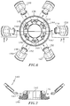
- FIG. 5 is an enlarged perspective view of the guard mount of the valve assembly of FIG. 2A illustrating the guard members supported by the guard mount;
- FIG. 6 is a top plan view of the guard mount of FIG. 5 with the guard elements disassembled from the guard mount;
- FIG. 7 is a cross-sectional view taken along the lines 7-7 of FIG. 6;
- FIGS. 8A-8C are cross-sectional views of a portion of a single guard mount illustrating a preferred method for pivotally connecting a guard element to the guard mount;
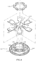
- FIG. 9 is an alternative two-piece guard mount to be incorporated in the valve assembly of FIG. 2A and illustrates a preferred method for mounting the guard elements to the guard mount;
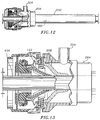
- FIG. 10 is a side plan view in partial cross-section of the cannula housing and the valve assembly detachably mounted the cannula housing of the cannula assembly;
- FIG. 11 is an enlarged cross-sectional view illustrating the valve assembly and the cannula housing;
- FIG. 12 is a view similar to FIG. 10 illustrating the introduction of an elongated object into the valve assembly and cannula assembly;
- FIG. 13 is a view similar to FIG. 11 illustrating sealing engagement of the resilient seal member of the valve assembly with the elongated object;
- FIG. 14 is a view similar to FIG. 12 illustrating the adaptability of the valve assembly to radial movement of the elongated object in the cannula assembly;
- FIG. 15 is a view similar to FIG. 13 further depicting the adaptability of the valve assembly to accommodate for radial movement of the elongated member;
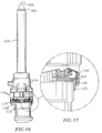
- FIG. 16 is a side plan view in partial cross-section of an assembled trocar and cannula assembly in combination with the valve assembly of FIG. 2A;
- FIG. 17 is an enlarged isolated view of the mechanism for detachably securing the trocar assembly relative to the valve assembly;
- FIG. 18 is an enlarged perspective view of an alternative guard mount to be incorporated in the valve assembly of FIG. 2A;
- FIG. 19 is an enlarged perspective view of a single guard element of the guard mount of FIG. 18 illustrating the mounting of the guard element to the guard mount; and
- FIG. 20 is a cross-sectional view of the valve assembly with the guard mount of FIG. 18.
- The present disclosure contemplates the introduction into a person's body of all types of surgical instruments including clip appliers, graspers, dissectors, retractors, staplers, laser fibers, photographic devices, endoscopes and laparoscopes, tubes, and the like. All such objects are referred to herein as "instruments".
- Referring initially to FIG. 1, there is illustrated the
novel valve assembly 100 constructed in accordance with the principles of the present disclosure and intended to be used in combination with a conventional trocar assembly consisting ofcannula assembly 200 andtrocar assembly 300. - The valve assembly of the present disclosure, either alone or in combination with a valve unit/seal assembly internal to
cannula 200, and either integral with or detachably mounted tocannula 200, provides a substantial seal between a body cavity of a patient and the outside atmosphere, both, during and subsequent to insertion of an instrument through the cannula. Moreover, thevalve assembly 100 of the present disclosure is capable of accommodating instruments of varying diameter, e.g. from 5mm to 12mm, by providing a gas tight seal with each instrument when inserted. The flexibility of the present valve assembly greatly facilitates endoscopic surgery where a variety of instruments having differing diameters are often needed during a single surgical procedure. - The valve assembly is preferably detachably mountable to the proximal end of
cannula 200 disclosed herein. Thus, the surgeon can remove thevalve assembly 100 from thecannula assembly 200 at any time during the surgical procedure and, similarly, mount theassembly 100 to the cannula when desired to provide a sealing engagement with an instrument to be inserted through the cannula. In addition, thevalve assembly 100 may be readily adapted to be mounted to conventional cannulas of differing structures. The detachability ofvalve assembly 100 fromcannula 200 facilitates specimen removal throughcannula 200 and reduces the profile ofcannula 200 when valve assembly is not needed for the surgical procedure. - Referring now to FIGS. 2A and 2B, the novel valve assembly of the present disclosure will be discussed in detail. As shown in the exploded view of Fig. 2A,
Valve assembly 100 includesend cap 102,stabilizer plate 104,guard mount 106,guard holder 108,seal element 110 and sealhousing 112.End cap 102,stabilizer plate 104 and sealhousing 112 form the outer valve body of the assembly, which houses the sealing and dilating components of the system, i.e.,guard mount 106,guard holder 108 andseal element 110. -
End cap 102 is generally cylindrically-shaped and includes aproximal end portion 103 defining a diameter which is less than the diameter of the remaining portion of the end cap and an innerperipheral ledge 114 which supportsstabilizer plate 104.Guard holder 108 is ring-like in configuration and includes inner and outerperipheral grooves Grooves guard mount 106 withinseal 110.Seal housing 112 includescentral opening 116, a proximalcylindrical portion 118 and a distalouter flange 120 having a scalloped surface to facilitate handling thereof.Cylindrical portion 118 is received withinend cap 102 when the valve assembly is fully assembled to enclose the sealing components. The distal end face ofseal housing 112 includes aperipheral groove 122 and twoopposed rib portions 124 extending radially inwardly adjacent thegroove 122. Groove 122 andrib portions 124 assist in mountingvalve assembly 100 to cannula 200 as will be appreciated from the description provided below. The distal end face ofseal housing 112 also includes asecond groove 126adjacent opening 116 for accommodating a portion ofseal 110. - Referring now to FIGS. 2A, 3 and 4, sealing
element 110 includes a generally frusto-conicalinterior portion 128 definingaperture 130, acircumferential flange portion 132 at its proximal end and circumferential bellowsstructure 134 disposed adjacent the distal end of theseal 110 and having distalouter flange portion 135.Seal 110 is fabricated from an elastomeric material such as synthetic or natural rubber which is preferably sufficiently resilient to accommodate and provide a fluid seal with instruments of varying diameters inserted throughaperture 130, e.g., instruments ranging in diameter from about 5mm to about 12 mm, and sufficiently resilient to flex atbellows structure 134 to accommodate manipulation of instrumentation inserted throughaperture 130. A plurality of generally longitudinally extendingribs 136 are disposed along the inner surface of frusto-conical portion 128.Ribs 136 provide additional support to seal 110 and are intended to engage the elongated instrument upon insertion thereof through the seal to minimize the potential of damage such as cutting or tearing of the seal by the distal end of the instrument.Flanges seal 110 to the valve body as will be appreciated from the following description.Seal 110 may also include at least one aligningprojection 133 extending from its proximal face to assist in mounting the seal to guardmount 106. Preferably seal 110 includes threeprojections 133. - Referring now to FIG. 2A, in conjunction with FIGS. 5-7,
guard mount 106 ofvalve assembly 100 will be discussed.Guard mount 106 includes anannular base portion 138 and a plurality ofguard elements 140 pivotally mounted relative to the base portion.Base portion 138 defines acentral opening 142 which is variably dimensioned to permit passage of an instrument therethrough, as discussed below, and an outercircumferential flange 144 at its proximal end.Circumferential flange 144 includes acircumferential lip 147 and threeapertures 145 correspondingly dimensioned to accommodate the three aligningprojections 133 extending from seal 110 (FIG.2A). -
Guard mount 106 also includes a plurality of slots 146 (Fig. 6) defined in the outer wall ofbase portion 138 for accommodating the proximal ends ofguard elements 140.Slots 146 are equidistantly disposed aboutbase portion 138 and extend generally longitudinally from a position intermediate the proximal and distal ends of theguard mount 106 through the distal end face of thebase portion 138. - Each
guard element 140 includes a finger-like portion 148 and anouter flap portion 150 connected at distal end offinger portion 148.Flap portion 150 may be joined tofinger portion 148 in a variety of manners, e.g., adhesive or insert molding, orflap portion 150 andfinger portion 148 may preferably be an integrally molded component.Finger portions 148 are accommodated withinrespective slots 146 inguard mount 106 and include a pair of opposed projectingmembers 152 extending outwardly from their proximal ends (Fig. 6). Projectingmembers 152 serve in pivotally mountingguard elements 140 to guardmount 106. - As best shown in FIGS. 7 and 8A-8C, the
outer flap 150 of eachguard element 140 defines first andsecond portions proximal portion 154 has a cross-sectional dimension or thickness which is greater than the thickness of the second ordistal portion 156 of theouter flap 150. Preferably,first portion 154 is from about two to about three times thicker in cross-sectional dimension thansecond portion 156. This dimensional ratio translates tosecond portion 156 being about two to three times more flexible thanfirst portion 154, assuming the same material of construction. Such dimensioning ofouter flap 150 ensures thatguard elements 140 are sufficiently rigid to cause stretching of theseal surface portions 110defining seal aperture 130 to thereby increase the dimension of theaperture 130 and facilitate insertion of the instrument therethrough and, in addition, provide sufficient flexibility to minimize the force required to advance the instrument through the guard element and seal arrangement. - More specifically, by the strategic dimensioning of the
guard elements 140 the following characteristics are present: 1) thefinger portion 148 in combination with the relative thickfirst portion 154 ofouter flap 150 provides a substantially rigid section of theguard element 140, which section is capable of sufficiently engaging the inner frusto-conical surface 128 ofseal 110 and enlarging theaperture 130 of the seal by displacing seal portions defining theaperture 130 radially outwardly; and 2) the relatively thin and less rigid, i.e., relatively,second portion 156 ofouter flap 150 reduces the force required to pass the instrument through the guard mount and seal arrangement and, also, minimizes the risk of damage to the inner surface of the seal by providing a protective interface between the instrument and the inner wall. Inasmuch asguard elements 140 are pivotally mounted toguard mount 106, as an instrument contactsouter flap 150 along its length, i.e., both alongfirst portion 154 andsecond portion 156,outer flap 150 is pivoted relative to projectingmembers 152 againstseal 110 in dilating contact therewith. - Guard elements are fabricated from a suitable material such as high density polyethylene, and, as noted above, are preferably monolithically formed by injection molding techniques to define a single element. It is also possible for the
finger portion 148 andflap portion 150 ofguard element 140 to be individually formed and subsequently connected by adhesives or the like. - Referring now to FIGS. 6, 7, and 8A-8C, the mounting of each
guard element 140 to guardmount 106 will be discussed in detail. Eachguard element 140 is individually mounted within aslot 146 inbase portion 138 ofguard mount 106 by inserting theproximal finger portion 148 within the base of the slot as shown in FIG. 8A and advancing the guard element into the slot such that the opposed projectingmembers 152 snap into correspondingly dimensioned grooves 158 (FIGS. 8A-8C) formed inportions 160 ofbase 138 adjacent each slot.(see FIG. 6) FIG. 8B depicts the projectingmembers 152 locked intogrooves 158. Thereafter, eachguard element 140 is pivoted upwardly to its appropriate position as shown in FIG. 8C. - FIG. 9 illustrates an alternative guard mount 162, and assembly method therefor, to be incorporated in the
valve assembly 100 of the present disclosure. In accordance with this embodiment, guard mount 162 includeslower half section 164 andupper half section 166 positionable on the lower half section. Guard mount 162 is substantially identical in configuration to theguard mount 106 described in connection with FIGS. 5-7 except that this guard mount 162 is provided with aradial groove 168 which is disposed adjacent eachslot 170. In further accordance with this embodiment, theguard elements 140 are simultaneously integrally molded to define a single unit as shown in FIG. 9. In the single molded unit, eachguard element 140 is appropriately positioned and oriented to be placed within acorresponding slot 170 within thelower half section 164 of guard mount 162, i.e., during assembly, the single unit is positioned against thelower section 164 withguard elements 140 being received within theslot portions 170. Thereafter, the central moldedportion 172 and thestems 174 interconnecting theguard elements 140 and the central molded portion are removed leaving theguard elements 140 within their respective slots. It is to be appreciated that a portion ofstem 174 connected to eachguard element 140 may remain after removal of thecentral portion 172. This stem portion is received withinradial groove 168 in assembly and serves to resist any tendency of theguard element 140 to rotate out of itsrespective slot 170. Once theguard elements 140 are positioned within theirrespective slots 170 with theopposed projections 152 in place withingrooves 176 in guard mount 162, theupper section 166 of the guard mount is attached to the lower section by adhesives, spot welding or the like. The assembledguard mount 160 andguard elements 140 operate in a similar manner to that described in connection withmount 106 of FIG. 5. - Referring again to FIG. 5, the
guard elements 140 in their fully assembled position may be oriented define a generally frusto-conical configuration so as to be positioned within the frusto-conical portion 128 ofseal 110. Preferably,guard elements 140 are arranged in overlapping relation, i.e., wherebyouter flap portions 150 ofadjacent guard elements 140 overlap each other to define a general iris-like arrangement of the guard elements. This desired arrangement is achieved by pivoting afirst guard element 140 inwardly and thereafter sequentially pivoting the remaining guard elements onto each other. Once all theguard elements 140 are in a fully pivoted position, the leading edge of theouter flap portion 150 of the last pivotedguard element 140 is tucked under the trailing edge of theflap portion 150 of the first pivoted guard element to provide the arrangement shown in Fig. 5. - Referring now to FIGS. 2A-2B, in conjunction with FIGS. 10-11, the assembling of the components of
valve assembly 100 will be discussed in detail. Although in FIGS. 10 and 11 thevalve assembly 100 is shown already mounted tocannula 200, it is to be appreciated that generallyvalve assembly 100 is first assembled as a single unit and then mounted to the cannula. The mounting ofvalve assembly 100 tocannula 200 will be discussed below.Stabilizer plate 104 is positioned withinend cap 102 such that theplate 104 rests on innerperipheral ledge 114 defined within theend cap 102. Thereafter,guard holder 108 is positioned over the proximal flange 132 (FIG. 4) ofseal 110 whereby the innerperipheral groove 109 of theguard holder 108 receives and accommodates theproximal flange 132 of theseal 110. Thereafter,seal 110 andguard holder 108 are positioned over guard mount 106 (FIG. 5) and advanced onto the mount untilproximal flange 132 of the seal is abuttingcircumferential flange 144 of themount 106 and aligningprojections 133 are received withinapertures 139 formed in thecircumferential flange 144 as shown in cross-section in FIG. 11. In this position, thecircumferential lip 147 on circumferential flange 144 (Fig. 5) is received within theouter groove 111 ofguard holder 108. - Assembly is continued by placing the assembled
seal 110,guard holder 108 andguard mount 106 subassembly againststabilizer plate 104 which is positioned againstledge 114 withinend cap 102. Thereafter, sealhousing 112 is positioned over the entire unit with thecylindrical wall 118 of the seal housing being received within the cylindrical wall ofend cap 102. In this assembled condition, the distal end portion of the cylindrical wall ofend cap 102 is received within an annular space defined betweendistal flange 120 ofseal housing 112 andcylindrical wall 118 ofseal housing 112 and retained therein by a friction or snap fit, thus retaining the valve assembly in a fully assembled condition. It is to be noted that in the assembled condition thedistal flange 135 ofbellows structure 134 ofseal 110 is positioned over the distal face ofseal housing 112 wherein theflange 135 is received within secondcircumferential groove 126 of the seal housing. - The
valve assembly 100 now in its fully assembled condition can be mounted tocannula 200. Referring to FIGS. 1, 10 and 11,cannula 200 is part of a trocar assembly and includes acannula sleeve 202 and acannula housing 204 mounted on one end of the sleeve.Sleeve 202 defines a cannula passage in its interior and may be formed of stainless steel or other rigid materials such as polymeric materials or the like. -
Cannula housing 204 is rigidly secured to the proximal end ofcannula 202 and defines a longitudinal opening for reception and passage of an elongated surgical instrument. The proximal end portion of thecannula housing 204 defines a generally circular cross-section and possesses diametricallyopposed leg portions 206. Acannula seal 208 fabricated from a resilient material, e.g., rubber, is positioned within the interior ofcannula housing 204.Seal 208 includes acircumferential flange portion 210 which rests on a correspondingly dimensionedcircumferential ledge 212 withincannula housing 204.Seal 208 generally defines a duck bill shape having twoplanar tapering portions 214 which intersect at their distal ends to defineabutment face 216. Theplanar tapering portions 214 may each include one or more inwardly directed, longitudinally oriented ribs to facilitate instrument passage.Abutment face 216 permits passage of the elongated object through theseal 208, but in the absence of an instrument, and particularly whencannula 202 is inserted into an insufflated body cavity,abutment face 216 forms a gas-tight seal that isolates the insufflated cavity from the ambient surroundings.Seal 208 also includes at least one, preferably two, reinforcingribs 215 to stabilize the seal.Ribs 215 are positioned to engage the instrument to guide the instrument throughslits 216 and prevent piercing of theseal 208 by the tip of the instrument. -
Cannula 200 also includes a stabilizing plate 218 (Fig. 1) which is positioned against theflange portion 210 ofseal 208 to provide support for the seal during introduction and withdrawal of an elongated instrument. Stabilizingplate 218 includes two diametrically opposed extensions 220 (FIG .1) which are received within the correspondingly dimensionedleg portions 206 of thecannula housing 204. In the preferred embodiment, stabilizingplate 218 is securely attached tocannula housing 204 at contact points along the extensions of the respective components by spot welding, adhesives or the like. Stabilizingplate 218 also includes a partial external annular rib or thread 222 (FIG. 11) adjacent its proximal end, the function of which will be appreciated from the description below. - A
stop cock valve 224 may be incorporated as part ofcannula housing 204 to permit the passage of insufflation gases through the cannula and into the body cavity. A suitable valve for this purpose is available from the Burron OEM Division of B. Braun Medical, Inc. (Model No. 55401022). - Referring still to FIGS. 1, 10 and 11, the mounting of
valve assembly 100 tocannula housing 204 will be discussed. The assembledvalve assembly 100 is detachably mounted adjacent stabilizingplate 218 with the partial annular thread 222 of the stabilizingplate 218 being received within the peripheral groove 122 (Fig. 2a) defined in the distal face ofseal housing 112. Thevalve assembly 100 is rotated to cause engagement of the radially inwardly projectingrib portions 124adjacent groove 122 with the partial annular thread 222 to releasably lock thevalve assembly 200 to the cannula housing. Other means for detachably connecting thevalve assembly 100 tocannula housing 204 can be readily determined by one skilled in the art such as screw threads, adhesives, bayonet locking, and the like. - Referring now to FIGS. 12 and 13, an elongated object such as a surgical instrument, identified generally as
numeral 400, may be inserted through thevalve assembly 100 and into thecannula 200 to perform the desired diagnostic procedure and/or surgery. As the surgical instrument enters the valve assembly, the tip of the surgical instrument is engaged by theguard elements 140. Upon further advancement of the surgical instrument, theguard elements 140 are pivoted radially outwardly to bias the seal member in an outward direction thereby stretching the seal portions defining theaperture 130 and increasing the dimension of the aperture to the degree necessary to accommodateinstrument 400. As previously stated, the particular dimensioning of theguard elements 140, i.e. the rigid section in combination with the more flexible outer portion, ensures adequate stretching of theseal element 110 while also permitting relatively easy passage ofinstrument 400 through the valve assembly. In addition, the overlapping arrangement of theouter flap portions 150 of the guard elements facilitate dilation of the seal aperture and minimize the potential for the distal end of the instrument to contact and pierce the resilient material of the inner surface ofseal 110 by providing an interface between the guard elements and the seal. Theresilient seal member 110 sealingly engages to form a substantial fluid-tight seal about the surgical instrument and a fluid tight seal within the valve housing and the external atmosphere. Theinstrument 400 is advanced through thecannula 200 whereby the duckbill seal of the cannula also spreads to allow passage of the instrument. Once positioned within thevalve assembly 100 andcannula 200, the surgical instrument may be maneuvered about the internal body cavity. - As shown in FIGS. 14-15, the valve assembly permits limited unencumbered movement of the instrument in a radial direction (relative to the centerline of cannula 202) while still maintaining an adequate seal about the instrument. This is due to the strategic spacing of the inner valve components, i.e.,
guard mount 106 andseal 110, relative to the valve body, i.e.,end cap 102 and sealhousing 112, and thebellows structure 134 of theseal 110. In particular, thebellows structure 134 provides sufficient flexibility to permit the valve components to "float" within the valve housing while still preserving the integrity of the seals established about the surgical instrument and within the cannula assembly. Thus, manipulation of the instrument in any direction, either longitudinally or radially, to he extent permitted by the rigid housings and cannula, will not effect the seal, since the resilient material of the seal element and the bellows structure will conform to the movements of the instrument and assume a desired shape necessary to retain sealing contact with the instrument. - Referring now to FIGS. 1, 16 and 17, the
novel valve assembly 100 may be used with a trocar of the type described in the figures. Thistrocar 300 is disclosed in U.S. Patent 5,356,421; and includestrocar housing 302, anobturator 304 extending distally from thehousing 302 and having piercingtip 306 and a stationary ortube 308 which houses the obturator when it is unarmed.Obturator 304 is advanced beyond the distal end ofcannula 202 to expose theobturator tip 306 by advancingactuating button 310. Thistrocar 300 also includes a lockinghinge 312 within thetrocar housing 302 which is actuated upon depression of theactuating lever 310. - The
trocar housing 302 may be longitudinally fixed relative tovalve assembly 100 andcannula 200 by inserting the trocar within the aperture defined inend cap 102 of theassembly 100, advancing the trocar through the valve assembly and intocannula sleeve 202, and advancingactuating button 310. Theproximal end portion 103 ofend cap 102 defines a smaller diameter than the remaining or main portion of the cap 102 (See also Fig. 11) and, thus, defines acircumferential locking ledge 105 at its intersection with the main cap portion. Once thetrocar 300 is appropriately positioned in thecannula 202, theobturator 304 andobturator tip 306 are advanced by advancingactuating button 310 which causes corresponding radial outward movement of thehinge member 312 and engagement of thehinge member 312 with thecircumferential locking ledge 105 of theend cap 102 as shown in FIG. 17 to detachably secure thetrocar housing 302 relative to thevalve assembly 100 andcannula assembly 200. Because lockingledge 105 extends circumferentially,trocar housing 302 may be detachably secured tovalve assembly 100 at any relative angular orientation. The valve assembly is capable of forming a seal about the trocar in the same manner described above. - In operation, the distal end of the
trocar 300 having theobturator tip 306 in an exposed position beyond thecannula 202 of thecannula assembly 200 is placed against the skin at the body cavity region, and pressure is exerted on the assembly against the skin. This pressure causes theobturator tip 306 to enter the skin and underlying tissue. Once the tip has penetrated the tissue and has entered the cavity, the tip automatically retracts into the cannula as described in U.S. Patent No. 5,116,353, and the trocar can be withdrawn from the cannula assembly to permit introduction of surgical instruments such as forceps, graspers, or the like through the remainingcannula 200. Alternatively, a trocar having a spring biased protective sleeve such as is described in U.S. Patent No. 4,601,710 or a conventional trocar which does not include a safety mechanism may be employed throughvalve assembly 100 andcannula assembly 200. It is to be appreciated that upon removal of thetrocar 300 from thecannula 200, theduck bill 208 closes automatically to preserve the state of insufflation of the peritoneum. In particular, the pressure exerted by the insufflation gases through thecannula sleeve 202 biases the planar portions 214 (Fig. 14) of theduck bill 208 towards each other thereby closing theabutment face 216 defined at the juncture of the two planar portions. - FIGS. 18-20 depict an
alternate guard mount 180 to be incorporated in the valve assembly of the present disclosure. In accordance with this embodiment, theguard elements 182 are mounted to the guard mount via tworods 184 which are connected at their first ends to theguard element 182 via insert molding techniques and at the second ends to apivot rod 186 within the guard mount. Theguard elements 186 pivot in a similar manner to that described in connection with the embodiment of FIG. 1 and possess a rigid section as defined by thefinger portion 188 and a more flexible outer section as defined byouter flap 190. - The claims which follow identify embodiments of the invention additional to those described in detail above.
Claims (17)
- Valve assembly for sealed reception of an elongate object, which comprises:a) valve body having at least one opening configured and dimensioned to permit entry of the elongate object and defining a central longitudinal axis;b) an elongate seal member formed of a resilient material and defining an aperture in general alignment with the opening of the valve body, the aperture being configured and dimensioned such that insertion of the object into the aperture causes the resilient material defining the aperture to resiliently engage the outer surface of the object in a substantially fluid flight manner; andc) at least one elongate guard member disposed within the seal member in contact with the inner surface thereof, the guard member positioned to engage the elongate object upon at least partial insertion of the elongated object into the valve body, the guard member including at least a first substantially rigid portion and a second portion having less rigidity than the first portion, the guard member adapted to be displaced relative to the longitudinal axis to facilitate expansion of the aperture of the seal member upon entry of the object therein.
- The valve assembly according to claim 1 wherein the second portion of the guard member is positioned adjacent the aperture of the seal member to provide an interface between the elongate object and the seal member to thereby protect the resilient material defining the aperture from damage from the elongate object.
- The valve assembly according to claim 1 or 2 wherein the guard member is a monolithically formed integral unit.
- The valve assembly according to claim 1,2 or 3 wherein the first portion of the guard member defines a cross-sectional dimension which is greater than the cross-sectional dimension of the second portion of the guard member.
- The valve assembly according to claim 1 wherein the guard member is fabricated from a material selected from high density polyethylene, low density polyethylene, and low density polyethylene with a polytetra fluorethylene additive.
- A valve assembly for sealed reception of an elongate object, which comprises:a) a valve housing having a longitudinal opening configured and dimensioned to permit entry of the elongate object;b) an elongate resilient seal member at least partially positionable within the valve housing and defining an aperture to permit entry of the elongate object therein in a substantially fluid tight manner; andc) a plurality of guard members disposed within the seal member and concentrically arranged about a central longitudinal axis defined by the valve housing and positioned to engage the elongate object upon insertion of the elongate object within the valve housing, each guard member adapted to be radially displaced during introduction of the elongate object within the valve assembly to engage portions of the valve member defining the aperture to expand the aperture, each guard member having an end portion of less rigidity than the remaining portions of the guard member, the end portion dimensioned to reduce the force required to advance the elongated object through the valve housing.
- The valve assembly according to any one of the preceding claims wherein each guard member is pivotally mounted at a proximal end thereof to a generally annular guard mount.
- The valve assembly according to any one of the preceding claims wherein adjacent end portions of the guard members overlap.
- The valve assembly according to any one of the preceding claims wherein the end portions of the guard members are positioned adjacent the aperture of the seal member to dilate the seal member aperture upon introduction of the elongate object.
- The valve assembly according to any one of the preceding claims wherein the elongate seal member includes a central frusto-conical portion defining the aperture and a circumferential portion, the circumferential portion including a bellows structure, the bellows structure engageable with the valve housing and dimensioned to maintain a substantially fluid tight seal with the valve housing notwithstanding manipulation of the elongated object within the aperture.
- The valve assembly according to any one of the preceding claims wherein the proximal end of the seal member includes a circumferential flange.
- The valve assembly according to claim 11, further including an annular guard holder disposed about the seal member, the guard holder engagable with the circumferential flange of the seal member and dimensioned to retain the circumferential flange against the annular guard mount to maintain the substantially fluid tight seal of the valve member.
- The valve assembly according to any one of the preceding claims wherein the seal housing and the valve member define therebetween a space to permit radial movement of the valve member within the valve housing.
- An assembly for the introduction of elongate objects into the body of a patient while maintaining a substantially fluid tight seal between internal body portions and the outside atmosphere, which comprises:a) a cannula including a cannula housing and a cannula sleeve extending distally from the cannula housing;b) a valve assembly mounted to the cannula assembly, the valve assembly including:i) a valve body having at least one opening configured and dimensioned to permit entry of an elongate object and defining a central longitudinal axis;ii) an elongate seal member formed of a resilient material and defining an aperture in general alignment with the opening of the valve body, the aperture being configured and dimensioned such that insertion of the object into the aperture causes the resilient material defining the aperture to resiliently engage the outer surface of the object in a substantially fluid flight manner; andiii) a plurality of guard members disposed within the seal member and concentrically arranged about a central longitudinal axis defined by the valve body and positioned to engage the elongate object upon insertion of the elongate object within the valve body, each guard member adapted to be radially displaced upon contact with the elongate object to engage the seal member to expand the aperture, each guard member having an end portion of less rigidity than the remaining portions of the guard member, the end portions dimensioned to reduce the force required to advance the elongate object through the valve body; andc) means for detachably connecting the valve assembly to the cannula housing.
- The assembly according to claim 14 wherein the cannula housing includes a member disposed therein, the member moveable between a substantially closed position in the absence of an object to an open position in the presence of an object.
- The assembly according to claim 15 wherein the member is of a duck-bill shape.
- The assembly according to claim 15 or 16 wherein the member of the cannula housing includes at least one longitudinally extending reinforcing ribs for providing additional support to the member, the reinforcing ribs positioned to engage the elongate object upon insertion therethrough.
Applications Claiming Priority (2)
| Application Number | Priority Date | Filing Date | Title |
|---|---|---|---|
| US08/287,395 US5603702A (en) | 1994-08-08 | 1994-08-08 | Valve system for cannula assembly |
| US287395 | 1994-08-08 |
Publications (2)
| Publication Number | Publication Date |
|---|---|
| EP0696459A1 true EP0696459A1 (en) | 1996-02-14 |
| EP0696459B1 EP0696459B1 (en) | 1998-11-04 |
Family
ID=23102708
Family Applications (1)
| Application Number | Title | Priority Date | Filing Date |
|---|---|---|---|
| EP95112151A Expired - Lifetime EP0696459B1 (en) | 1994-08-08 | 1995-08-02 | Valve system for cannula assembly |
Country Status (7)
| Country | Link |
|---|---|
| US (2) | US5603702A (en) |
| EP (1) | EP0696459B1 (en) |
| JP (6) | JP4068170B2 (en) |
| AU (1) | AU692275B2 (en) |
| CA (1) | CA2154125C (en) |
| DE (1) | DE69505750T2 (en) |
| ES (1) | ES2123192T3 (en) |
Cited By (38)
| Publication number | Priority date | Publication date | Assignee | Title |
|---|---|---|---|---|
| EP0873721A2 (en) * | 1997-04-25 | 1998-10-28 | Ethicon Endo-Surgery, Inc. | Trocar having protector with flexible end and improved seal assembly |
| NL1007997C2 (en) * | 1998-01-09 | 1999-07-12 | Cordis Europ | Device for inserting an elongated medical device. |
| EP1127550A1 (en) * | 2000-02-25 | 2001-08-29 | United States Surgical Corporation | Valve assembly |
| EP1314392A1 (en) * | 2001-11-27 | 2003-05-28 | Karl Storz GmbH & Co. | Seal for endoscope |
| EP1443991A1 (en) * | 2001-11-13 | 2004-08-11 | Applied Medical Resources Corporation | Multi-seal trocar system |
| EP1459688A1 (en) * | 2003-03-21 | 2004-09-22 | Ethicon Endo-Surgery, Inc. | Improved conical trocar seal |
| EP1520542A1 (en) * | 2003-09-30 | 2005-04-06 | Ethicon Endo-Surgery, Inc. | Rotational latching system for a trocar |
| EP1545660A1 (en) * | 2002-10-04 | 2005-06-29 | Applied Medical Resources Corporation | Surgical access device with pendent valve |
| EP1582158A1 (en) * | 2004-03-31 | 2005-10-05 | Ethicon Endo-Surgery, Inc. | Trocar seal |
| EP1651096A2 (en) * | 2003-08-08 | 2006-05-03 | Taut, Inc. | Seal positioning assembly |
| EP1716813A1 (en) * | 2005-04-25 | 2006-11-02 | Tyco Healthcare Group Lp | Surgical portal with seal system |
| US7163525B2 (en) | 2004-12-17 | 2007-01-16 | Ethicon Endo-Surgery, Inc. | Duckbill seal protector |
| WO2007148959A1 (en) * | 2006-06-20 | 2007-12-27 | Avesto Tech Bv | Access port valve assembly |
| WO2008029092A3 (en) * | 2006-09-07 | 2008-05-08 | Gyrus Medical Ltd | Surgical instrument |
| US7371227B2 (en) | 2004-12-17 | 2008-05-13 | Ethicon Endo-Surgery, Inc. | Trocar seal assembly |
| EP1889580A3 (en) * | 2006-07-07 | 2008-11-05 | Tyco Healthcare Group Lp | Surgical seal assembly |
| US7481795B2 (en) | 2004-12-17 | 2009-01-27 | Ethicon Endo-Surgery, Inc. | Circumferential trocar seal assembly |
| WO2009076146A1 (en) * | 2007-12-07 | 2009-06-18 | Ethicon Endo-Surgery, Inc. | Trocar seal with reduced contact area |
| US7597701B2 (en) | 2003-09-30 | 2009-10-06 | Ethican Endo-Surgery, Inc. | Instrument lock assembly for trocar |
| EP2138111A1 (en) * | 2002-10-04 | 2009-12-30 | ConMed Corporation | Trocar system |
| EP2147646A3 (en) * | 2008-07-23 | 2010-06-02 | Karl Storz GmbH & Co. KG | Medical instrument with a flexible seal system |
| EP1969991A3 (en) * | 2007-03-14 | 2010-07-21 | Fujinon Corporation | Endoscope advancing apparatus |
| US7785294B2 (en) | 2003-09-30 | 2010-08-31 | Ethicon Endo-Surgery, Inc. | Woven protector for trocar seal assembly |
| US7896877B2 (en) | 2004-05-20 | 2011-03-01 | Gyrus Medical Limited | Surgical instrument |
| US8012128B2 (en) | 2003-09-30 | 2011-09-06 | Ethicon Endo-Surgery Inc. | Button latching system for a trocar |
| US8029475B2 (en) | 2003-09-30 | 2011-10-04 | Ethicon Endo-Surgery, Inc. | Reinforced seal assembly |
| US8034032B2 (en) | 2003-09-30 | 2011-10-11 | Ethicon Endo-Surgery, Inc. | Multi-angled duckbill seal assembly |
| US8206411B2 (en) | 2003-09-30 | 2012-06-26 | Ethicon Endo-Surgery, Inc. | Trocar housing/stop-cock assembly |
| US8568362B2 (en) | 2008-04-28 | 2013-10-29 | Ethicon Endo-Surgery, Inc. | Surgical access device with sorbents |
| US8636686B2 (en) | 2008-04-28 | 2014-01-28 | Ethicon Endo-Surgery, Inc. | Surgical access device |
| USD700326S1 (en) | 2008-04-28 | 2014-02-25 | Ethicon Endo-Surgery, Inc. | Trocar housing |
| US8771307B2 (en) | 2007-06-29 | 2014-07-08 | Ethicon Endo-Surgery, Inc. | Duckbill seal with fluid drainage feature |
| US8911407B2 (en) | 2005-04-25 | 2014-12-16 | Covidien Lp | Surgical portal with seal system |
| US8932275B2 (en) | 2006-07-07 | 2015-01-13 | Covidien Lp | Surgical seal assembly |
| US9033929B2 (en) | 2008-04-28 | 2015-05-19 | Ethicon Endo-Surgery, Inc. | Fluid removal in a surgical access device |
| CN110075418A (en) * | 2013-03-15 | 2019-08-02 | 波顿医疗公司 | Haemostatic valve and transportation system |
| CN111248981A (en) * | 2013-03-15 | 2020-06-09 | 直观外科手术操作公司 | Sealing multiple surgical instruments |
| US11235111B2 (en) | 2008-04-28 | 2022-02-01 | Ethicon Llc | Surgical access device |
Families Citing this family (250)
| Publication number | Priority date | Publication date | Assignee | Title |
|---|---|---|---|---|
| DE4401237C2 (en) * | 1994-01-18 | 1997-06-05 | Ruesch Willy Ag | Trocar device |
| US5603702A (en) * | 1994-08-08 | 1997-02-18 | United States Surgical Corporation | Valve system for cannula assembly |
| US5599305A (en) * | 1994-10-24 | 1997-02-04 | Cardiovascular Concepts, Inc. | Large-diameter introducer sheath having hemostasis valve and removable steering mechanism |
| US6245072B1 (en) * | 1995-03-27 | 2001-06-12 | Sdgi Holdings, Inc. | Methods and instruments for interbody fusion |
| US5792113A (en) * | 1996-12-12 | 1998-08-11 | Ethicon Endo-Surgerym Inc. | Universal seal for a trocar |
| JP4647727B2 (en) * | 1997-05-02 | 2011-03-09 | ユナイテッド ステイツ サージカル コーポレイション | Trocar sealing device |
| EP1849489B1 (en) * | 1997-05-02 | 2009-10-07 | United States Surgical Corporation | Cannula assembly |
| US5779697A (en) * | 1997-05-28 | 1998-07-14 | Linvatec Corporation | Arthroscopic cannula with fluid seals |
| CA2291838C (en) | 1997-05-28 | 2006-07-18 | David C. Racenet | Trocar seal system |
| US5916198A (en) * | 1997-08-05 | 1999-06-29 | Femrx, Inc. | Non-binding surgical valve |
| USRE39499E1 (en) * | 1998-01-15 | 2007-02-27 | Epimed International, Inc. | Catheter connector |
| US5993437A (en) * | 1998-01-15 | 1999-11-30 | Epimed International, Inc. | Catheter connector |
| US6190372B1 (en) * | 1998-08-14 | 2001-02-20 | Epimed International, Inc. | Catheter connector |
| US6228061B1 (en) * | 1998-02-03 | 2001-05-08 | Imagyn Medical Technologies California, Inc. | Trocar seal system having dual seals |
| US6036711A (en) * | 1998-02-18 | 2000-03-14 | United States Surgical Corporation | Reusable cannula |
| US5989224A (en) | 1998-02-23 | 1999-11-23 | Dexide Corporation | Universal seal for use with endoscopic cannula |
| US6093176A (en) | 1998-03-10 | 2000-07-25 | Core Dynamics, Inc. | Trocar with disposable valve and reusable cannula |
| USD426635S (en) * | 1998-08-18 | 2000-06-13 | Genicon, Lc | Combination trocar, cannula, and valve |
| US6409967B1 (en) * | 1998-11-06 | 2002-06-25 | Medtronic, Inc. | Valve obturator |
| US6860869B2 (en) * | 1999-03-26 | 2005-03-01 | William G. Dennis | Surgical instrument seal assembly |
| US6258065B1 (en) | 1999-03-26 | 2001-07-10 | Core Dynamics, Inc. | Surgical instrument seal assembly |
| US8992085B2 (en) * | 1999-06-24 | 2015-03-31 | Alan D. Olin | Self-supporting storage bag with resealable pour spout |
| WO2001012086A1 (en) | 1999-08-13 | 2001-02-22 | The Johns Hopkins University | Device and method for rapid chest tube insertion |
| DE60028244T2 (en) | 1999-12-30 | 2007-03-15 | Cook Vascular Inc. | DISCONNECTABLE MEDICAL VALVE |
| USD449887S1 (en) | 2000-01-26 | 2001-10-30 | Genicon Lc | Combined obturator, cannula and valve assembly |
| US7153319B1 (en) | 2000-01-26 | 2006-12-26 | Genico, Inc. | Trocar system having shielded trocar |
| USD443360S1 (en) | 2000-03-22 | 2001-06-05 | Dexterity Surgical Inc. | Distal end of obturator for a trocar |
| US6740064B1 (en) * | 2000-05-08 | 2004-05-25 | Tyco Healthcare Group Lp | Reusable nonmetallic cannula |
| GB0012461D0 (en) * | 2000-05-24 | 2000-07-12 | Surgical Innovations Ltd | Surgical seal |
| US6699221B2 (en) * | 2000-06-15 | 2004-03-02 | Vincent L. Vaillancourt | Bloodless catheter |
| DE20015388U1 (en) * | 2000-09-06 | 2001-03-15 | Storm Gerald | Device for sealing and lubricating instruments guided in trocar sleeves |
| US20060020281A1 (en) * | 2000-10-13 | 2006-01-26 | Smith Robert C | Valve assembly including diameter reduction structure for trocar |
| ES2312474T3 (en) * | 2000-10-13 | 2009-03-01 | Tyco Healthcare Group Lp | VALVE ASSEMBLY THAT INCLUDES A DIAMETER REDUCTION STRUCTURE FOR A TROCAR. |
| EP1326524B1 (en) | 2000-10-19 | 2010-09-01 | Applied Medical Resources Corporation | Surgical access apparatus and method |
| US6942671B1 (en) * | 2000-11-06 | 2005-09-13 | Tyco Healthcare Group Lp | Surgical sealing apparatus |
| US20050187524A1 (en) * | 2000-12-19 | 2005-08-25 | Willis Allan F. | Sealing valve assembly for medical products |
| US6767340B2 (en) | 2000-12-19 | 2004-07-27 | Kimberly-Clark Worldwide, Inc. | Sealing valve assembly for medical products |
| US6908449B2 (en) * | 2000-12-19 | 2005-06-21 | Kimberly-Clark Worldwide, Inc. | Sealing valve assembly for medical products |
| EP1416981B1 (en) | 2001-08-14 | 2013-07-24 | Applied Medical Resources Corporation | Access sealing apparatus |
| US20050033246A1 (en) | 2002-05-14 | 2005-02-10 | Ahlberg Russell E. | Surgical device with tack-free gel and method of manufacture |
| US6989003B2 (en) * | 2001-08-31 | 2006-01-24 | Conmed Corporation | Obturator and cannula for a trocar adapted for ease of insertion and removal |
| US20040260244A1 (en) * | 2001-08-31 | 2004-12-23 | Piechowicz Michael E. | Seals for trocars |
| US6958037B2 (en) * | 2001-10-20 | 2005-10-25 | Applied Medical Resources Corporation | Wound retraction apparatus and method |
| US7052454B2 (en) * | 2001-10-20 | 2006-05-30 | Applied Medical Resources Corporation | Sealed surgical access device |
| CA2452338C (en) * | 2002-04-26 | 2009-02-24 | Taut, Inc. | Floating seal assembly for a trocar |
| US7632250B2 (en) | 2002-05-10 | 2009-12-15 | Tyco Healthcare Group Lp | Introducer seal assembly |
| JP4527528B2 (en) * | 2002-06-05 | 2010-08-18 | アプライド メディカル リソーシーズ コーポレイション | Wound retractor |
| US9055995B2 (en) * | 2002-11-04 | 2015-06-16 | Aspire Bariatrics, Inc. | Method for treating obesity by extracting food |
| US7815629B2 (en) | 2002-11-04 | 2010-10-19 | Deka Products Limited Partnership | Apparatus for treating obesity by extracting food |
| US7740624B2 (en) * | 2002-11-04 | 2010-06-22 | Aspiration Medical Technology, Llc | Method for treating obesity by extracting food |
| US7217275B2 (en) * | 2003-01-14 | 2007-05-15 | Crabtree John H | Tunnel port apparatus with serial gas-check assembly |
| US7214228B2 (en) * | 2003-01-14 | 2007-05-08 | Crabtree John H | Tunnel port apparatus |
| US20050020884A1 (en) | 2003-02-25 | 2005-01-27 | Hart Charles C. | Surgical access system |
| WO2004096012A2 (en) * | 2003-04-25 | 2004-11-11 | Tyco Healthcare Group Lp | Surgical hand access apparatus |
| GB0313730D0 (en) * | 2003-06-13 | 2003-07-16 | Surgical Innovations Ltd | Improved surgical seal |
| US20040267202A1 (en) * | 2003-06-26 | 2004-12-30 | Potter Daniel J. | Tearable hemostasis valve and splittable sheath |
| US7241276B2 (en) * | 2003-08-06 | 2007-07-10 | Trivascular, Inc. | Passive hemostatic sheath valve |
| US7163510B2 (en) * | 2003-09-17 | 2007-01-16 | Applied Medical Resources Corporation | Surgical instrument access device |
| EP1663344A4 (en) * | 2003-09-24 | 2007-11-14 | Applied Med Resources | Anti-inversion trocar seal |
| US20050070850A1 (en) * | 2003-09-30 | 2005-03-31 | Albrecht Thomas E. | Low-profile, recessed stop-cock valve for trocar assembly |
| AU2004214617B2 (en) * | 2003-09-30 | 2010-09-09 | Ethicon Endo-Surgery, Inc. | Reinforced seal assembly |
| AU2004216609B2 (en) * | 2003-09-30 | 2010-08-12 | Ethicon Endo-Surgery, Inc. | Rotational latching system for a trocar |
| DE10346612A1 (en) * | 2003-10-08 | 2005-05-19 | Robert Bosch Gmbh | Method for forecasting a temporal development of a system size |
| US20050131349A1 (en) * | 2003-12-12 | 2005-06-16 | Applied Medical Resources Corporation | Shielded septum trocar seal |
| US7842013B2 (en) * | 2004-01-23 | 2010-11-30 | Genico, Inc. | Trocar and cannula assembly having conical valve and related methods |
| US20060047293A1 (en) * | 2004-01-23 | 2006-03-02 | Haberland Gary W | Trocar having planar fixed septum seal and related methods |
| US7585288B2 (en) * | 2004-01-23 | 2009-09-08 | Genico, Inc. | Trocar and cannula assembly having conical valve and related methods |
| US20050165433A1 (en) * | 2004-01-23 | 2005-07-28 | Haberland Gary W. | Trocar having planar fixed septum seal and related methods |
| US20050209607A1 (en) | 2004-03-22 | 2005-09-22 | John Lipchitz | Medical cannula assembly |
| WO2005107843A1 (en) | 2004-04-30 | 2005-11-17 | C.R. Bard, Inc. | Valved sheath introducer for venous cannulation |
| US20070066988A1 (en) * | 2005-09-22 | 2007-03-22 | Keshava Datta | Trocar obturator with cutting edges |
| CA2574276C (en) * | 2004-07-21 | 2013-03-19 | Tyco Healthcare Group, Lp | Introducer assembly with suspended seal |
| US8241251B2 (en) * | 2004-08-25 | 2012-08-14 | Tyco Healthcare Group Lp | Gel seal for a surgical trocar apparatus |
| US8403890B2 (en) | 2004-11-29 | 2013-03-26 | C. R. Bard, Inc. | Reduced friction catheter introducer and method of manufacturing and using the same |
| US9597483B2 (en) | 2004-11-29 | 2017-03-21 | C. R. Bard, Inc. | Reduced-friction catheter introducer and method of manufacturing and using the same |
| US8926564B2 (en) | 2004-11-29 | 2015-01-06 | C. R. Bard, Inc. | Catheter introducer including a valve and valve actuator |
| US8932260B2 (en) | 2004-11-29 | 2015-01-13 | C. R. Bard, Inc. | Reduced-friction catheter introducer and method of manufacturing and using the same |
| US20060149137A1 (en) * | 2005-01-05 | 2006-07-06 | Applied Medical Resources Corporation | Easily placeable and removable wound retractor |
| US7608082B2 (en) * | 2005-01-06 | 2009-10-27 | Tyco Healthcare Group Lp | Surgical seal for use in a surgical access apparatus |
| US20060212062A1 (en) | 2005-03-16 | 2006-09-21 | David Farascioni | Radially expandable access system including trocar seal |
| US20060229655A1 (en) * | 2005-03-30 | 2006-10-12 | Ethicon Endo-Surgery, Inc. | Two part bullet assembly |
| US7931624B2 (en) * | 2005-04-05 | 2011-04-26 | Tyco Healthcare Group Lp | Introducer seal assembly with low profile gimbal seal |
| US7837612B2 (en) * | 2005-04-08 | 2010-11-23 | Ethicon Endo-Surgery, Inc. | Tissue suspension device |
| EP1933733A2 (en) | 2005-10-14 | 2008-06-25 | Applied Medical Resources Corporation | Surgical access port |
| WO2007047332A1 (en) | 2005-10-14 | 2007-04-26 | Applied Medical Resources Corporation | Split hoop wound retractor with gel pad |
| DE102006001255A1 (en) * | 2006-01-10 | 2007-07-12 | B. Braun Melsungen Ag | catheter device |
| WO2007098495A2 (en) * | 2006-02-22 | 2007-08-30 | Applied Medical Resources Corporation | Trocar seal |
| DE102006015690A1 (en) * | 2006-03-27 | 2007-10-11 | Aesculap Ag & Co. Kg | Surgical sealing element, surgical seal and surgical sealing system |
| US8579807B2 (en) * | 2008-04-28 | 2013-11-12 | Ethicon Endo-Surgery, Inc. | Absorbing fluids in a surgical access device |
| US8690831B2 (en) * | 2008-04-25 | 2014-04-08 | Ethicon Endo-Surgery, Inc. | Gas jet fluid removal in a trocar |
| US8915842B2 (en) * | 2008-07-14 | 2014-12-23 | Ethicon Endo-Surgery, Inc. | Methods and devices for maintaining visibility and providing irrigation and/or suction during surgical procedures |
| FR2902015B1 (en) | 2006-06-13 | 2009-03-06 | Claude Mialhe | ADAPTER FOR INTRODUCER VALVE IN HUMAN OR ANIMAL BODY |
| US20080177295A1 (en) * | 2006-06-29 | 2008-07-24 | Dario Vitali | Surgical device having trocar and associated methods |
| AU2007269591A1 (en) * | 2006-07-05 | 2008-01-10 | Aspiration Medical Technology, Llc | Shunt apparatus for treating obesity by extracting food |
| US20110082442A1 (en) * | 2006-07-05 | 2011-04-07 | Solovay Kenneth S | Externally reinforced percutaneous gastrostomy tube with customizable smooth tube length |
| US8414561B2 (en) | 2006-08-03 | 2013-04-09 | Aspire Bariatrics, Llc | Systems and methods for removing ingested material from a stomach |
| US8632513B2 (en) * | 2006-08-03 | 2014-01-21 | Aspire Bariatrics, Inc. | Systems and methods for removing ingested material from a stomach |
| CA2660831C (en) | 2006-08-25 | 2012-10-02 | Teleflex Medical Incorporated | Caged floating seal assembly |
| US7806870B2 (en) * | 2006-10-06 | 2010-10-05 | Surgiquest, Incorporated | Elastically deformable surgical access device having telescoping guide tube |
| US7798998B2 (en) | 2006-10-06 | 2010-09-21 | Surgiquest, Inc. | Elastically deformable surgical access device |
| WO2010042913A2 (en) * | 2006-10-06 | 2010-04-15 | Surgiquest, Incorporated | Devices for and methods of performing minimally-invasive surgical procedures through a single incision |
| US8257315B2 (en) * | 2006-10-11 | 2012-09-04 | Ethicon Endo-Surgery, Inc. | Trocar seal with retraction induced hinge |
| US7798991B2 (en) * | 2006-11-14 | 2010-09-21 | Genico, Inc. | Trocar and cannula assembly having variable opening sealing gland and related methods |
| US20080171988A1 (en) * | 2007-01-17 | 2008-07-17 | Erblan Surgical, Inc. | Double-cone sphincter introducer assembly and integrated valve assembly |
| DE102007008751A1 (en) * | 2007-02-22 | 2008-08-28 | Wisap Gesellschaft für wissenschaftlichen Apparatebau mbH | Device for cutting out and removing cylinders of tissue from tissue, has cutting device with hollow-cylindrical base body and distal opening on distal end of base body, where cutting element is provided for surrounding distal opening |
| ES2623049T3 (en) * | 2007-05-11 | 2017-07-10 | Applied Medical Resources Corporation | Surgical retractor |
| CA2682923C (en) * | 2007-05-11 | 2014-10-07 | Applied Medical Resources Corporation | Surgical retractor with gel pad |
| ES2373072T3 (en) * | 2007-05-22 | 2012-01-31 | Tyco Healthcare Group Lp | ACCESS SET WITH TRIQUITA BOARD. |
| CA2631607A1 (en) * | 2007-05-22 | 2008-11-22 | Tyco Healthcare Group Lp | Surgical portable apparatus with variable adjustment |
| US7981086B2 (en) * | 2007-05-22 | 2011-07-19 | Tyco Healthcare Group Lp | Surgical access assembly with winepress seal |
| EP1994894A1 (en) * | 2007-05-22 | 2008-11-26 | Tyco Healthcare Group LP | Access assembly with ribbed seal |
| CA2631825A1 (en) * | 2007-05-24 | 2008-11-24 | Tyco Healthcare Group Lp | Surgical portal apparatus with armature assembly |
| US7762990B2 (en) * | 2007-05-24 | 2010-07-27 | Tyco Healthcare Group Lp | Surgical access apparatus with centering mechanism |
| US8133174B2 (en) * | 2007-05-30 | 2012-03-13 | Tyco Healthcare Group Lp | Self constricting orifice seal |
| CA2632369A1 (en) * | 2007-05-31 | 2008-11-30 | Tyco Healthcare Group Lp | Access apparatus with shallow zero closure valve |
| US7918826B2 (en) | 2007-09-14 | 2011-04-05 | Ethicon Endo-Surgery, Inc. | Trocar assembly |
| US20090076465A1 (en) * | 2007-09-17 | 2009-03-19 | Tyco Healthcare Group Lp | Composite seal and method for manufacturing |
| US8357123B2 (en) * | 2007-09-17 | 2013-01-22 | Covidien Lp | Surgical portal with gel and fabric seal assembly |
| US20090093682A1 (en) * | 2007-10-05 | 2009-04-09 | Tyco Healthcare Group Lp | Surgical portal with foam and fabric composite seal assembly |
| US20090105635A1 (en) * | 2007-10-17 | 2009-04-23 | Tyco Healthcare Group Lp | Access assembly with seal lubricant mechanism |
| CN101903062A (en) | 2007-10-19 | 2010-12-01 | C·R·巴德股份有限公司 | Introducer including shaped distal region |
| US9352129B2 (en) | 2007-12-13 | 2016-05-31 | Medical Components, Inc. | Introducer assembly with cap and method of using same |
| EP2237815B1 (en) * | 2008-01-22 | 2020-08-19 | Applied Medical Resources Corporation | Surgical instrument access device |
| EP2656803B1 (en) * | 2008-03-14 | 2016-05-18 | Applied Medical Resources Corporation | Instrument seal |
| US8075530B2 (en) * | 2008-03-20 | 2011-12-13 | Applied Medical Resources Corporation | Instrument seal with inverting shroud |
| US7828775B2 (en) | 2008-04-11 | 2010-11-09 | Tyco Healthcare Group Lp | Telescoping cannula |
| US8870747B2 (en) * | 2008-04-28 | 2014-10-28 | Ethicon Endo-Surgery, Inc. | Scraping fluid removal in a surgical access device |
| US9358041B2 (en) * | 2008-04-28 | 2016-06-07 | Ethicon Endo-Surgery, Llc | Wicking fluid management in a surgical access device |
| US7981092B2 (en) * | 2008-05-08 | 2011-07-19 | Ethicon Endo-Surgery, Inc. | Vibratory trocar |
| IL279542B2 (en) * | 2008-06-13 | 2023-10-01 | Mannkind Corp | A dry powder inhaler and system for drug delivery |
| US9028448B2 (en) * | 2008-06-19 | 2015-05-12 | Covidien Lp | Access seal with interstitial channels |
| US8012129B2 (en) * | 2008-06-25 | 2011-09-06 | Tyco Healthcare Group Lp | Surgical portal apparatus with waffle seal |
| US8197446B2 (en) | 2008-06-25 | 2012-06-12 | Tyco Healthcare Group Lp | Access cannula with hinge restrictor |
| US7901380B2 (en) * | 2008-06-25 | 2011-03-08 | Tyco Healthcare Group Lp | Iris seal for surgical port |
| US7850667B2 (en) * | 2008-06-27 | 2010-12-14 | Tyco Healthcare Group Lp | Low profile instrument access device |
| US8021339B2 (en) * | 2008-07-01 | 2011-09-20 | Tyco Healthcare Group Lp | Surgical portal apparatus with centering mechanism |
| DE102008033374A1 (en) | 2008-07-09 | 2010-01-14 | Aesculap Ag | Surgical protection device for a surgical sealing element and surgical sealing system |
| DE102008033375A1 (en) | 2008-07-09 | 2010-01-14 | Aesculap Ag | Surgical sealing element holder for holding a surgical sealing element and surgical sealing system |
| DE202008009527U1 (en) | 2008-07-09 | 2008-10-02 | Aesculap Ag | Surgical protection device for a surgical sealing element and surgical sealing system |
| US7914491B2 (en) | 2008-07-17 | 2011-03-29 | Tyco Healthcare Group Lp | Constricting mechanism for use with a surgical access assembly |
| DE102008035311A1 (en) | 2008-07-23 | 2010-01-28 | Karl Storz Gmbh & Co. Kg | Medical instrument with laterally displaceable seal |
| WO2010045253A1 (en) | 2008-10-13 | 2010-04-22 | Applied Medical Resources Corporation | Single port access system |
| WO2010048542A1 (en) * | 2008-10-23 | 2010-04-29 | Michael Patton | Cannula seal |
| US20100194060A1 (en) * | 2008-11-03 | 2010-08-05 | Erblan Surgical, Inc. | Universal closure and method of lubrication |
| BRPI0917035A2 (en) | 2008-12-04 | 2019-09-24 | Pivot Medical Inc | "telescope access cannula, telescope shutter, system, method for providing an access corridor from a first off-site location to a second on-site location" |
| US20100174143A1 (en) * | 2009-01-06 | 2010-07-08 | Tyco Healthcare Group Lp | Dual seal with bellows |
| WO2010081105A1 (en) | 2009-01-09 | 2010-07-15 | Applied Medical Resources Corporation | Pleated trocar shield |
| US10278728B2 (en) * | 2009-01-30 | 2019-05-07 | St. Jude Medical, Llc | Transapical mini-introducer hemostasis valve and punch |
| US9839415B2 (en) | 2009-01-30 | 2017-12-12 | St. Jude Medical, Llc | Apex closure device |
| US8628056B2 (en) * | 2009-02-02 | 2014-01-14 | Aptargroup, Inc. | Dual sealing system for use with a probe |
| US20100240957A1 (en) * | 2009-03-17 | 2010-09-23 | Abrams Michael E | Access port including centering feature |
| US9078697B2 (en) * | 2009-03-18 | 2015-07-14 | Covidien Lp | Surgical portal apparatus including movable housing |
| US8206357B2 (en) * | 2009-03-26 | 2012-06-26 | Tyco Healthcare Group Lp | Articulating surgical portal apparatus with spring |
| US8328717B2 (en) * | 2009-03-27 | 2012-12-11 | Covidien Lp | Seal device with adjustable aperture |
| US8206358B2 (en) * | 2009-05-06 | 2012-06-26 | Tyco Healthcare Group Lp | Ring and seal for trocar |
| US9138207B2 (en) | 2009-05-19 | 2015-09-22 | Teleflex Medical Incorporated | Methods and devices for laparoscopic surgery |
| US8409084B2 (en) * | 2009-08-31 | 2013-04-02 | Covidien Lp | Surgical portal apparatus including gear and lockout assembly |
| JP6247003B2 (en) | 2009-08-31 | 2017-12-13 | アプライド メディカル リソーシーズ コーポレイション | Multi-function surgical access system |
| US8430812B2 (en) * | 2009-10-05 | 2013-04-30 | Covidien Lp | Surgical access assembly |
| US20110087159A1 (en) * | 2009-10-08 | 2011-04-14 | Parihar Shailendra K | Trocar Assembly |
| US8932249B2 (en) * | 2009-10-08 | 2015-01-13 | Ethicon Endo-Surgery, Inc. | Trocar assembly |
| US8491533B2 (en) * | 2009-10-08 | 2013-07-23 | Ethicon Endo-Surgery, Inc. | Trocar assembly |
| US8454563B2 (en) | 2009-10-09 | 2013-06-04 | Rogelio A. Insignares | Trocar and cannula assembly having improved conical valve, and methods related thereto |
| US20110152622A1 (en) * | 2009-12-18 | 2011-06-23 | Oivind Brockmeier | Surgical access apparatus with constraining mechanism |
| US8025641B2 (en) * | 2009-12-18 | 2011-09-27 | Tyco Healthcare Group Lp | Powered variable seal diameter trocar employing a winepress mechanism |
| US8721539B2 (en) | 2010-01-20 | 2014-05-13 | EON Surgical Ltd. | Rapid laparoscopy exchange system and method of use thereof |
| WO2011089565A1 (en) | 2010-01-20 | 2011-07-28 | EON Surgical Ltd. | System of deploying an elongate unit in a body cavity |
| US8353874B2 (en) * | 2010-02-18 | 2013-01-15 | Covidien Lp | Access apparatus including integral zero-closure valve and check valve |
| US20110237900A1 (en) * | 2010-03-25 | 2011-09-29 | Tyco Healthcare Group Lp | Portal apparatus with a tubular seal device |
| US8702596B2 (en) * | 2010-09-17 | 2014-04-22 | United States Endoscopy Group, Inc. | Biopsy inlet valve improvements |
| EP2615980B1 (en) | 2010-09-19 | 2017-08-16 | EON Surgical Ltd. | Micro laparoscopy devices and deployments thereof |
| US8562520B2 (en) | 2010-10-01 | 2013-10-22 | Covidien Lp | Access port |
| US9289115B2 (en) | 2010-10-01 | 2016-03-22 | Applied Medical Resources Corporation | Natural orifice surgery system |
| CA2811753C (en) | 2010-10-01 | 2019-05-21 | Applied Medical Resources Corporation | Natural orifice surgery system |
| US9101315B2 (en) | 2010-11-11 | 2015-08-11 | Specialty Care, Inc. | Cannula system |
| US8821526B2 (en) | 2010-11-11 | 2014-09-02 | Specialtycare, Inc. | Trocar |
| US9119664B2 (en) * | 2010-12-20 | 2015-09-01 | Covidien Lp | Integral foam port |
| CN102551845B (en) * | 2010-12-21 | 2016-03-02 | 周星 | For annular sealing device and the perforator of perforator |
| WO2012118852A2 (en) | 2011-02-28 | 2012-09-07 | Normedix Llc | Hemostasis sealing device |
| JP6005143B2 (en) | 2011-05-10 | 2016-10-12 | アプライド メディカル リソーシーズ コーポレイション | Retractor |
| US8556183B2 (en) * | 2011-07-08 | 2013-10-15 | Gregory D. Bray | Systems and methods involving transferable identification tags |
| JP6106169B2 (en) | 2011-07-11 | 2017-03-29 | ボード オブ リージェンツ オブ ザ ユニバーシティ オブ ネブラスカ | Surgical robot system |
| ES2403782B1 (en) * | 2011-09-28 | 2014-03-05 | Jesús PEREIRO MALLO | VALVE FOR FEMALE CONNECTION ELEMENTS IN COMPONENTS OF PERIPHERAL INSERTION LINES. |
| US9320507B2 (en) | 2012-03-26 | 2016-04-26 | Covidien Lp | Cannula valve assembly |
| US9186173B2 (en) | 2012-04-27 | 2015-11-17 | Specialty Care, Inc. | Optical obturator system |
| EP2844181B1 (en) | 2012-05-01 | 2021-03-10 | Board of Regents of the University of Nebraska | Single site robotic device and related systems |
| WO2014025399A1 (en) | 2012-08-08 | 2014-02-13 | Board Of Regents Of The University Of Nebraska | Robotic surgical devices, systems, and related methods |
| WO2014130636A1 (en) | 2013-02-21 | 2014-08-28 | Covidien Lp | Surgical access device including lateral moving seal cooperating with bellows attached to proximal wall of cannula house |
| DK2958608T3 (en) | 2013-02-23 | 2019-06-03 | Aspire Bariatrics Inc | DEVICE AND PROCEDURE FOR DRAINING MATERIAL FROM A MAVE |
| KR102300866B1 (en) | 2013-03-15 | 2021-09-13 | 어플라이드 메디컬 리소시스 코포레이션 | Mechanical gel surgical access device |
| WO2015009949A2 (en) | 2013-07-17 | 2015-01-22 | Board Of Regents Of The University Of Nebraska | Robotic surgical devices, systems and related methods |
| US20150025477A1 (en) * | 2013-07-22 | 2015-01-22 | Covidien Lp | Surgical seal assembly including centering mechanism |
| WO2015069846A1 (en) * | 2013-11-07 | 2015-05-14 | Teleflex Medical Incorporated | Seal assembly having an anti-friction ring |
| US9782563B2 (en) * | 2014-06-05 | 2017-10-10 | Cure Medical, Llc | Catheter packaging with movement control device |
| WO2016007650A1 (en) * | 2014-07-08 | 2016-01-14 | Applied Medical Resources Corporation | Highly responsive instrument seal |
| EP3169510B1 (en) | 2014-07-18 | 2018-10-03 | Applied Medical Resources Corporation | Method for manufacturing gels having permanent tack free coatings |
| EP4101405A1 (en) | 2014-08-15 | 2022-12-14 | Applied Medical Resources Corporation | Natural orifice surgery system |
| CN105615954B (en) * | 2014-11-08 | 2018-10-12 | 广州迪克医疗器械有限公司 | Puncture outfit containing silencing means |
| JP2017535399A (en) | 2014-11-25 | 2017-11-30 | アプライド メディカル リソーシーズ コーポレイション | Surrounding wound retraction with support and guidance structure |
| GB201500328D0 (en) * | 2015-01-09 | 2015-02-25 | Cannula sealing | |
| ES2863572T3 (en) | 2015-05-15 | 2021-10-11 | Covidien Lp | Valve assembly for a surgical access device |
| WO2017024081A1 (en) * | 2015-08-03 | 2017-02-09 | Board Of Regents Of The University Of Nebraska | Robotic surgical devices systems and related methods |
| US10086164B2 (en) * | 2015-09-08 | 2018-10-02 | Jeng-Yu Chou | Medical joint and check valve module thereof |
| ES2937400T3 (en) | 2015-09-15 | 2023-03-28 | Applied Med Resources | Surgical Robotic Access System |
| KR20180066157A (en) | 2015-10-07 | 2018-06-18 | 어플라이드 메디컬 리소시스 코포레이션 | Wound retractor with multi-segment outer ring |
| JP6847854B2 (en) * | 2015-12-07 | 2021-03-24 | 京セラ株式会社 | Trocar |
| US10980952B2 (en) * | 2016-05-13 | 2021-04-20 | Intuitive Surgical Operations, Inc. | Universal cannula seal |
| CN114098975A (en) | 2016-05-18 | 2022-03-01 | 虚拟切割有限公司 | Robotic surgical devices, systems, and related methods |
| US10391292B2 (en) | 2016-06-15 | 2019-08-27 | Surmodics, Inc. | Hemostasis sealing device with constriction ring |
| ES2905900T3 (en) * | 2016-08-01 | 2022-04-12 | Poly Medicure Ltd | Intravenous catheter device with safety function and pressure-controlled valve element |
| CA3036192A1 (en) | 2016-09-12 | 2018-03-15 | Applied Medical Resources Corporation | Surgical robotic access system for irregularly shaped robotic actuators and associated robotic surgical instruments |
| JP6644664B2 (en) * | 2016-10-11 | 2020-02-12 | 京セラ株式会社 | Seal unit for trocar |
| CN107997811A (en) * | 2016-10-31 | 2018-05-08 | 广州迪克医疗器械有限公司 | Sealing ring screening glass, end seal assembly and puncture outfit for puncture outfit |
| US11511098B2 (en) * | 2016-11-09 | 2022-11-29 | Boston Scientific Limited | Low pressure seal design for a hemostasis valve |
| US10758719B2 (en) | 2016-12-15 | 2020-09-01 | Surmodics, Inc. | Low-friction sealing devices |
| US10874426B2 (en) | 2017-02-10 | 2020-12-29 | Covidien Lp | Seal assembly with integral filter and evacuation port |
| CN108568322A (en) * | 2017-03-09 | 2018-09-25 | 无锡市凯顺医疗器械制造有限公司 | A kind of leakage barriers are with test tube and take the fit structure and leakage barriers of liquid part |
| US10463830B2 (en) | 2017-07-06 | 2019-11-05 | Cure Medical, Llc | Packaged urinary catheter with dispensing control device |
| US10980974B2 (en) | 2017-08-08 | 2021-04-20 | Cure Medical Llc | Methods of dispensing a urinary catheter from a sterile package |
| US10315008B2 (en) | 2017-08-08 | 2019-06-11 | Cure Medical Llc | Packaged urinary catheter with catheter dispensing system |
| US10814097B2 (en) | 2017-08-08 | 2020-10-27 | Cure Medical, Llc | Packaged urinary catheter with dispensing device |
| US10792069B2 (en) * | 2017-09-26 | 2020-10-06 | Ethicon Llc | Trocar seal assemblies |
| US10758270B2 (en) * | 2017-10-06 | 2020-09-01 | Ethicon Llc | Surgical tool stabilization devices for trocar assemblies |
| AU2019205201B2 (en) | 2018-01-04 | 2020-11-05 | Covidien Lp | Systems and assemblies for mounting a surgical accessory to robotic surgical systems, and providing access therethrough |
| CN117140580A (en) | 2018-01-05 | 2023-12-01 | 内布拉斯加大学董事会 | Single arm robotic device with compact joint design and related systems and methods |
| JP2021536306A (en) * | 2018-09-17 | 2021-12-27 | アルコン インコーポレイティド | Low friction trocar valve |
| CN114302665A (en) | 2019-01-07 | 2022-04-08 | 虚拟切割有限公司 | Robot-assisted surgical system and related devices and methods |
| US10792071B2 (en) | 2019-02-11 | 2020-10-06 | Covidien Lp | Seals for surgical access assemblies |
| US11166748B2 (en) * | 2019-02-11 | 2021-11-09 | Covidien Lp | Seal assemblies for surgical access assemblies |
| WO2020223628A1 (en) * | 2019-05-02 | 2020-11-05 | Gajjar Aakash | Implantable surgical device, system and method of use |
| US11413068B2 (en) | 2019-05-09 | 2022-08-16 | Covidien Lp | Seal assemblies for surgical access assemblies |
| US11259841B2 (en) | 2019-06-21 | 2022-03-01 | Covidien Lp | Seal assemblies for surgical access assemblies |
| US20200397470A1 (en) | 2019-06-21 | 2020-12-24 | Covidien Lp | Seals for surgical access assemblies |
| US11259840B2 (en) | 2019-06-21 | 2022-03-01 | Covidien Lp | Valve assemblies for surgical access assemblies |
| US11357542B2 (en) | 2019-06-21 | 2022-06-14 | Covidien Lp | Valve assembly and retainer for surgical access assembly |
| US11413065B2 (en) | 2019-06-28 | 2022-08-16 | Covidien Lp | Seal assemblies for surgical access assemblies |
| US11439429B2 (en) | 2019-07-11 | 2022-09-13 | New View Surgical | Cannula assembly with deployable camera |
| US11399865B2 (en) | 2019-08-02 | 2022-08-02 | Covidien Lp | Seal assemblies for surgical access assemblies |
| US11523842B2 (en) | 2019-09-09 | 2022-12-13 | Covidien Lp | Reusable surgical port with disposable seal assembly |
| US11432843B2 (en) | 2019-09-09 | 2022-09-06 | Covidien Lp | Centering mechanisms for a surgical access assembly |
| US11406420B2 (en) | 2019-10-11 | 2022-08-09 | Covidien Lp | Two point contact flange for instrument seals |
| US11812991B2 (en) | 2019-10-18 | 2023-11-14 | Covidien Lp | Seal assemblies for surgical access assemblies |
| JP2021087775A (en) | 2019-12-04 | 2021-06-10 | コヴィディエン リミテッド パートナーシップ | Seal assemblies for surgical access assemblies |
| US20210228233A1 (en) | 2020-01-28 | 2021-07-29 | Covidien Lp | Seal assemblies for surgical access assemblies |
| US11642153B2 (en) | 2020-03-19 | 2023-05-09 | Covidien Lp | Instrument seal for surgical access assembly |
| US11541218B2 (en) | 2020-03-20 | 2023-01-03 | Covidien Lp | Seal assembly for a surgical access assembly and method of manufacturing the same |
| US11446058B2 (en) | 2020-03-27 | 2022-09-20 | Covidien Lp | Fixture device for folding a seal member |
| US11717321B2 (en) | 2020-04-24 | 2023-08-08 | Covidien Lp | Access assembly with retention mechanism |
| US20220022915A1 (en) | 2020-07-22 | 2022-01-27 | Covidien Lp | Trocar system with force sensing |
| US11219468B1 (en) | 2020-09-04 | 2022-01-11 | Covidien Lp | Trocar assembly with antimicrobial skirt |
Citations (12)
| Publication number | Priority date | Publication date | Assignee | Title |
|---|---|---|---|---|
| US4655752A (en) | 1983-10-24 | 1987-04-07 | Acufex Microsurgical, Inc. | Surgical cannula |
| US4874377A (en) | 1988-05-26 | 1989-10-17 | Davis Newgard Revocable Family Living Trust | Self-occluding intravascular cannula assembly |
| US4929235A (en) | 1985-07-31 | 1990-05-29 | Universal Medical Instrument Corp. | Self-sealing percutaneous tube introducer |
| US5064416A (en) | 1988-05-26 | 1991-11-12 | Newgard Kent W | Self-occluding intravascular cannula assembly |
| US5116353A (en) | 1990-10-05 | 1992-05-26 | United States Surgical Corporation | Safety trocar |
| EP0517248A1 (en) * | 1991-06-07 | 1992-12-09 | United States Surgical Corporation | Valve system for introducing object into anatomical body portions |
| EP0567141A2 (en) | 1992-04-24 | 1993-10-27 | United States Surgical Corporation | Valve assembly for introducing instruments into body cavities |
| EP0567142A2 (en) | 1992-04-24 | 1993-10-27 | United States Surgical Corporation | Valve assembly for introducing instruments into body cavities |
| US5300033A (en) | 1992-07-09 | 1994-04-05 | Unisurge, Inc. | Introducer assembly and valve construction for use therein |
| WO1994007552A1 (en) * | 1992-09-28 | 1994-04-14 | Applied Medical Resources Corporation | Protection for septum seal of a trocar |
| US5312363A (en) * | 1993-07-13 | 1994-05-17 | Symbiosis Corporation | Low friction slit valve |
| US5356421A (en) | 1992-10-07 | 1994-10-18 | United States Surgical Corporation | Safety trocar with locking handles |
Family Cites Families (80)
| Publication number | Priority date | Publication date | Assignee | Title |
|---|---|---|---|---|
| US2797837A (en) * | 1954-04-19 | 1957-07-02 | Roberts Charles Buford | Stopper for ampoules and the like |
| US3197173A (en) * | 1960-07-12 | 1965-07-27 | John H Van Dyke | Pinch valve |
| US3473779A (en) * | 1965-04-12 | 1969-10-21 | Henry E Gustafson | Flexible tube valve having positive opening and closing means |
| IL29264A (en) * | 1967-03-29 | 1970-08-19 | Latex Prod Ltd | Non-return valve for medical uses |
| US3875938A (en) * | 1973-08-22 | 1975-04-08 | Eli K Mellor | Multi-mode cannulating apparatus |
| US3970089A (en) * | 1974-08-05 | 1976-07-20 | Saice Dwayne D | Cardiovascular catheter seal device |
| US3977400A (en) * | 1974-11-29 | 1976-08-31 | Deseret Pharmaceutical Co., Inc. | Catheter placement unit with resilient sleeve and manual sleeve closure |
| US4000739A (en) * | 1975-07-09 | 1977-01-04 | Cordis Corporation | Hemostasis cannula |
| JPS6034241Y2 (en) * | 1977-04-25 | 1985-10-12 | オリンパス光学工業株式会社 | Endoscope passage sealing device |
| GB2012919B (en) * | 1977-11-24 | 1982-05-19 | Wolf Gmbh Richard | Trocar sleeves |
| US4379458A (en) * | 1977-11-24 | 1983-04-12 | Richard Wolf Gmbh | Trocar sleeves having a ball valve |
| US4177814A (en) * | 1978-01-18 | 1979-12-11 | KLI, Incorporated | Self-sealing cannula |
| DE2817102C2 (en) * | 1978-04-19 | 1985-01-24 | Dr. Eduard Fresenius, Chemisch-pharmazeutische Industrie KG, 6380 Bad Homburg | Connector for plastic cannulas or venous catheters |
| SE414272B (en) * | 1978-10-17 | 1980-07-21 | Viggo Ab | CANNEL OR CATETER DEVICE |
| DE2845643C2 (en) * | 1978-10-20 | 1982-04-08 | Max Dr. 8520 Erlangen Hubmann | Catheter connection head with at least one channel in a base body |
| US4496348A (en) * | 1979-11-29 | 1985-01-29 | Abbott Laboratories | Venipuncture device |
| ATE3242T1 (en) * | 1979-12-01 | 1983-05-15 | Intermedicat Gmbh | CATHETER CONNECTION HEAD WITH AT LEAST ONE CHANNEL IN A BASIC BODY. |
| US4338934A (en) * | 1980-02-19 | 1982-07-13 | Spademan Richard George | Intravascular catheter apparatus |
| DE3042229C2 (en) * | 1980-11-08 | 1983-10-27 | B. Braun Melsungen Ag, 3508 Melsungen | Insertion device for inserting elongated objects into blood vessels |
| DE3048774C2 (en) * | 1980-12-23 | 1984-03-08 | B. Braun Melsungen Ag, 3508 Melsungen | Catheterization device |
| US4430081A (en) * | 1981-01-06 | 1984-02-07 | Cook, Inc. | Hemostasis sheath |
| US4424833A (en) * | 1981-10-02 | 1984-01-10 | C. R. Bard, Inc. | Self sealing gasket assembly |
| DE3242870A1 (en) * | 1981-11-20 | 1983-06-01 | Machida Endoscope Co., Ltd., Tokyo | Arrangement for prevention of a return flow through the forceps insertion opening of an endoscope |
| US4535773A (en) * | 1982-03-26 | 1985-08-20 | Inbae Yoon | Safety puncturing instrument and method |
| US5308336A (en) * | 1982-09-28 | 1994-05-03 | Applied Medical Resources | Seal protection mechanism |
| US4512766A (en) * | 1982-12-08 | 1985-04-23 | Whitman Medical Corporation | Catheter valve |
| US4610665A (en) * | 1983-01-18 | 1986-09-09 | Terumo Kabushiki Kaisha | Medical instrument |
| US4531937A (en) * | 1983-01-24 | 1985-07-30 | Pacesetter Systems, Inc. | Introducer catheter apparatus and method of use |
| FR2545008A1 (en) * | 1983-04-27 | 1984-11-02 | Snap Duroc Sa | Fluid-substance applicator with adjustable drying |
| US4580573A (en) * | 1983-10-20 | 1986-04-08 | Medical Device Development Corporation, Inc. | Catheter introducer |
| ATE37793T1 (en) * | 1983-12-27 | 1988-10-15 | Pfister Lehmann Alfred | OCCLUSION ON A URINARY CATHETER. |
| JPS60234671A (en) * | 1984-05-09 | 1985-11-21 | テルモ株式会社 | Catheter inserter |
| US4569502A (en) * | 1984-09-04 | 1986-02-11 | Miller Sales & Engineering, Inc. | Pinch valve |
| JPS6171065A (en) * | 1984-09-13 | 1986-04-11 | テルモ株式会社 | Catheter introducer |
| GB2168459B (en) * | 1984-12-06 | 1988-07-13 | Craig Med Prod Ltd | Tube closure device |
| JPS61154679A (en) * | 1984-12-28 | 1986-07-14 | テルモ株式会社 | Medical instrument |
| US4634432A (en) * | 1985-05-13 | 1987-01-06 | Nuri Kocak | Introducer sheath assembly |
| US4626245A (en) * | 1985-08-30 | 1986-12-02 | Cordis Corporation | Hemostatis valve comprising an elastomeric partition having opposed intersecting slits |
| US4759751A (en) * | 1985-11-07 | 1988-07-26 | Becton, Dickinson And Company | Catheter assembly with air purging feature |
| US4654030A (en) * | 1986-02-24 | 1987-03-31 | Endotherapeutics | Trocar |
| GB8618253D0 (en) * | 1986-07-25 | 1986-09-03 | Wallace Ltd H G | Intermittent administration of therapeutic substance |
| US4683916A (en) * | 1986-09-25 | 1987-08-04 | Burron Medical Inc. | Normally closed automatic reflux valve |
| GB8627808D0 (en) * | 1986-11-20 | 1986-12-17 | Cox J A | Sampling liquids from human/animal body |
| US4813938A (en) * | 1987-09-17 | 1989-03-21 | Raulerson J Daniel | Catheter introduction syringe |
| DE3731242A1 (en) * | 1987-09-17 | 1989-03-30 | Joka Kathetertechnik Gmbh | SHUT-OFF DEVICE ON A LIQUID DRAWING OR INFUSION DEVICE |
| US4798594A (en) * | 1987-09-21 | 1989-01-17 | Cordis Corporation | Medical instrument valve |
| US4909798A (en) * | 1987-11-12 | 1990-03-20 | Daig Corporation | Universal hemostasis cannula |
| US4943280A (en) * | 1987-12-31 | 1990-07-24 | United States Surgical Corporaiton | Self-seating flapper valve for an insufflation cannula assembly |
| US4842591A (en) * | 1988-01-21 | 1989-06-27 | Luther Ronald B | Connector with one-way septum valve, and assembly |
| US4857062A (en) * | 1988-03-09 | 1989-08-15 | Medical Parameters, Inc. | Catheter introducer valve |
| DE3809127C1 (en) * | 1988-03-18 | 1989-04-13 | B. Braun Melsungen Ag, 3508 Melsungen, De | |
| DE8904025U1 (en) * | 1988-04-07 | 1989-05-24 | Schneider (Europe) Ag, Zuerich, Ch | |
| US4960412A (en) * | 1988-04-15 | 1990-10-02 | Universal Medical Instrument Corp. | Catheter introducing system |
| US4895346A (en) * | 1988-05-02 | 1990-01-23 | The Kendall Company | Valve assembly |
| US5009391A (en) * | 1988-05-02 | 1991-04-23 | The Kendall Company | Valve assembly |
| US5098393A (en) * | 1988-05-31 | 1992-03-24 | Kurt Amplatz | Medical introducer and valve assembly |
| CA1336060C (en) * | 1988-06-02 | 1995-06-27 | George W. Bourne, Iv | Self-sealing guidewire and catheter introducer |
| GB8816033D0 (en) * | 1988-07-06 | 1988-08-10 | Ethicon Inc | Improved safety trocar |
| US5000745A (en) * | 1988-11-18 | 1991-03-19 | Edward Weck Incorporated | Hemostatis valve |
| US4946133A (en) * | 1988-11-21 | 1990-08-07 | Schneider (U.S.A.) Inc., A Pfizer Co. | Hemostasis valve |
| US5127626A (en) * | 1989-10-31 | 1992-07-07 | Applied Vascular Devices, Inc. | Apparatus for sealing around members extending therethrough |
| US5053014A (en) * | 1990-02-01 | 1991-10-01 | Critikon, Inc. | Catheter with controlled valve |
| US5006114A (en) * | 1990-04-20 | 1991-04-09 | Rogers Bobby E | Medical valve assembly |
| US5161773A (en) * | 1990-08-01 | 1992-11-10 | Numed, Inc. | Method and apparatus for controlling fluid flow |
| US5156596A (en) * | 1991-02-04 | 1992-10-20 | Menlo Care, Inc. | Catheter with changeable number of lumens |
| US5205831A (en) * | 1991-04-22 | 1993-04-27 | Burron Medical, Inc. | Compression gasket for y-connector |
| US5092857A (en) * | 1991-05-17 | 1992-03-03 | Fleischhacker John J | Hemostasis valve having support shoulders |
| US5112321A (en) * | 1991-06-07 | 1992-05-12 | Richard Wolf Gmbh | Trocar sleeve having manual closure |
| US5211634A (en) * | 1991-08-06 | 1993-05-18 | Vaillancourt Vincent L | Composite seal structure and a coupling arrangement for a cannula |
| US5197955A (en) * | 1991-10-18 | 1993-03-30 | Ethicon, Inc. | Universal seal for trocar assembly |
| US5545142A (en) * | 1991-10-18 | 1996-08-13 | Ethicon, Inc. | Seal members for surgical trocars |
| US5167636A (en) * | 1991-10-24 | 1992-12-01 | Mectra Labs, Inc. | Cannula sealing mechanism |
| US5256150A (en) * | 1991-12-13 | 1993-10-26 | Endovascular Technologies, Inc. | Large-diameter expandable sheath and method |
| US5242412A (en) * | 1992-01-21 | 1993-09-07 | Blake Joseph W Iii | Trocar tube subassembly having sealing ring and duckbill sealing tube having planar, truncate, diverging sealing bills |
| US5496280A (en) * | 1992-07-02 | 1996-03-05 | Applied Medical Resources Corporation | Trocar valve assembly |
| US5312362A (en) * | 1993-02-04 | 1994-05-17 | Owens Precision Systems, Inc. | Seal for a cannula assembly |
| US5342315A (en) * | 1993-04-12 | 1994-08-30 | Ethicon, Inc. | Trocar seal/protector assemblies |
| US5492304A (en) * | 1993-06-16 | 1996-02-20 | United States Surgical Corporation | Seal assembly for accommodating introduction of surgical instruments |
| US5460616A (en) * | 1994-04-19 | 1995-10-24 | Cordis Corporation | Catheter introducer with fluid chamber valve |
| US5603702A (en) * | 1994-08-08 | 1997-02-18 | United States Surgical Corporation | Valve system for cannula assembly |
-
1994
- 1994-08-08 US US08/287,395 patent/US5603702A/en not_active Expired - Lifetime
-
1995
- 1995-07-18 CA CA002154125A patent/CA2154125C/en not_active Expired - Lifetime
- 1995-08-02 EP EP95112151A patent/EP0696459B1/en not_active Expired - Lifetime
- 1995-08-02 DE DE69505750T patent/DE69505750T2/en not_active Expired - Lifetime
- 1995-08-02 ES ES95112151T patent/ES2123192T3/en not_active Expired - Lifetime
- 1995-08-07 AU AU28408/95A patent/AU692275B2/en not_active Expired
- 1995-08-08 JP JP20258395A patent/JP4068170B2/en not_active Expired - Lifetime
-
1997
- 1997-02-18 US US08/802,188 patent/US5895377A/en not_active Expired - Lifetime
-
2006
- 2006-01-06 JP JP2006001274A patent/JP2006102539A/en not_active Withdrawn
- 2006-11-29 JP JP2006321740A patent/JP4184403B2/en not_active Expired - Lifetime
-
2007
- 2007-07-17 JP JP2007186373A patent/JP4184413B2/en not_active Expired - Lifetime
-
2009
- 2009-03-24 JP JP2009072934A patent/JP2009131716A/en not_active Withdrawn
-
2011
- 2011-06-09 JP JP2011129098A patent/JP2011194264A/en not_active Withdrawn
Patent Citations (13)
| Publication number | Priority date | Publication date | Assignee | Title |
|---|---|---|---|---|
| US4655752A (en) | 1983-10-24 | 1987-04-07 | Acufex Microsurgical, Inc. | Surgical cannula |
| US4929235A (en) | 1985-07-31 | 1990-05-29 | Universal Medical Instrument Corp. | Self-sealing percutaneous tube introducer |
| US4874377A (en) | 1988-05-26 | 1989-10-17 | Davis Newgard Revocable Family Living Trust | Self-occluding intravascular cannula assembly |
| US5064416A (en) | 1988-05-26 | 1991-11-12 | Newgard Kent W | Self-occluding intravascular cannula assembly |
| US5116353B1 (en) | 1990-10-05 | 1996-09-10 | Digital Voice Systems Inc | Safety trocar |
| US5116353A (en) | 1990-10-05 | 1992-05-26 | United States Surgical Corporation | Safety trocar |
| EP0517248A1 (en) * | 1991-06-07 | 1992-12-09 | United States Surgical Corporation | Valve system for introducing object into anatomical body portions |
| EP0567141A2 (en) | 1992-04-24 | 1993-10-27 | United States Surgical Corporation | Valve assembly for introducing instruments into body cavities |
| EP0567142A2 (en) | 1992-04-24 | 1993-10-27 | United States Surgical Corporation | Valve assembly for introducing instruments into body cavities |
| US5300033A (en) | 1992-07-09 | 1994-04-05 | Unisurge, Inc. | Introducer assembly and valve construction for use therein |
| WO1994007552A1 (en) * | 1992-09-28 | 1994-04-14 | Applied Medical Resources Corporation | Protection for septum seal of a trocar |
| US5356421A (en) | 1992-10-07 | 1994-10-18 | United States Surgical Corporation | Safety trocar with locking handles |
| US5312363A (en) * | 1993-07-13 | 1994-05-17 | Symbiosis Corporation | Low friction slit valve |
Cited By (67)
| Publication number | Priority date | Publication date | Assignee | Title |
|---|---|---|---|---|
| EP0873721A2 (en) * | 1997-04-25 | 1998-10-28 | Ethicon Endo-Surgery, Inc. | Trocar having protector with flexible end and improved seal assembly |
| EP0873721A3 (en) * | 1997-04-25 | 2000-02-23 | Ethicon Endo-Surgery, Inc. | Trocar having protector with flexible end and improved seal assembly |
| AU730756B2 (en) * | 1997-04-25 | 2001-03-15 | Ethicon Endo-Surgery, Inc. | Trocar having protector with flexible end and improved seal assembly |
| NL1007997C2 (en) * | 1998-01-09 | 1999-07-12 | Cordis Europ | Device for inserting an elongated medical device. |
| JP2001314516A (en) * | 2000-02-25 | 2001-11-13 | United States Surgical Corp | Valve assembly |
| EP1127550A1 (en) * | 2000-02-25 | 2001-08-29 | United States Surgical Corporation | Valve assembly |
| US8147458B2 (en) | 2001-11-13 | 2012-04-03 | Applied Medical Resources Corporation | Multi-seal trocar system |
| EP1443991A1 (en) * | 2001-11-13 | 2004-08-11 | Applied Medical Resources Corporation | Multi-seal trocar system |
| EP1443991A4 (en) * | 2001-11-13 | 2007-03-14 | Applied Med Resources | Multi-seal trocar system |
| US7438702B2 (en) | 2001-11-13 | 2008-10-21 | Applied Medical Resources Corporation | Multi-seal trocar system |
| EP1314392A1 (en) * | 2001-11-27 | 2003-05-28 | Karl Storz GmbH & Co. | Seal for endoscope |
| US6887193B2 (en) | 2001-11-27 | 2005-05-03 | Karl Storz Gmbh & Co. Kg | Sealing device for a rectoscope |
| EP2138111A1 (en) * | 2002-10-04 | 2009-12-30 | ConMed Corporation | Trocar system |
| EP1545660A1 (en) * | 2002-10-04 | 2005-06-29 | Applied Medical Resources Corporation | Surgical access device with pendent valve |
| EP1545660A4 (en) * | 2002-10-04 | 2008-12-31 | Applied Med Resources | Surgical access device with pendent valve |
| US8118785B2 (en) | 2002-10-04 | 2012-02-21 | Applied Medical Resources Corporation | Surgical access device with pendent valve |
| US7771395B2 (en) | 2002-10-04 | 2010-08-10 | Applied Medical Resources Corporation | Surgical access device with pendent valve |
| EP3002018A1 (en) * | 2002-10-04 | 2016-04-06 | Applied Medical Resources Corporation | Surgical access device with pendent valve |
| US8613727B2 (en) | 2002-10-04 | 2013-12-24 | Applied Medical Resources Corporation | Surgical access device with pendent valve |
| US8562569B2 (en) | 2002-10-04 | 2013-10-22 | Applied Medical Resources Corporation | Surgical access device with pendent valve |
| EP2397085A3 (en) * | 2002-10-04 | 2012-12-19 | Applied Medical Resources Corporation | Surgical access device with pendent valve |
| EP1459688A1 (en) * | 2003-03-21 | 2004-09-22 | Ethicon Endo-Surgery, Inc. | Improved conical trocar seal |
| US9486241B2 (en) | 2003-03-21 | 2016-11-08 | Ethicon Endo-Surgery, Llc | Trocar seal assembly |
| US8147457B2 (en) | 2003-03-21 | 2012-04-03 | Ethicon Endo-Surgery, Inc. | Conical trocar seal |
| EP1651096A2 (en) * | 2003-08-08 | 2006-05-03 | Taut, Inc. | Seal positioning assembly |
| EP1651096A4 (en) * | 2003-08-08 | 2008-05-21 | Teleflex Medical Inc | Seal positioning assembly |
| US8012128B2 (en) | 2003-09-30 | 2011-09-06 | Ethicon Endo-Surgery Inc. | Button latching system for a trocar |
| US7597701B2 (en) | 2003-09-30 | 2009-10-06 | Ethican Endo-Surgery, Inc. | Instrument lock assembly for trocar |
| EP1520542A1 (en) * | 2003-09-30 | 2005-04-06 | Ethicon Endo-Surgery, Inc. | Rotational latching system for a trocar |
| US8034032B2 (en) | 2003-09-30 | 2011-10-11 | Ethicon Endo-Surgery, Inc. | Multi-angled duckbill seal assembly |
| US8206411B2 (en) | 2003-09-30 | 2012-06-26 | Ethicon Endo-Surgery, Inc. | Trocar housing/stop-cock assembly |
| US7785294B2 (en) | 2003-09-30 | 2010-08-31 | Ethicon Endo-Surgery, Inc. | Woven protector for trocar seal assembly |
| US8029475B2 (en) | 2003-09-30 | 2011-10-04 | Ethicon Endo-Surgery, Inc. | Reinforced seal assembly |
| EP1582158A1 (en) * | 2004-03-31 | 2005-10-05 | Ethicon Endo-Surgery, Inc. | Trocar seal |
| US7896877B2 (en) | 2004-05-20 | 2011-03-01 | Gyrus Medical Limited | Surgical instrument |
| US7163525B2 (en) | 2004-12-17 | 2007-01-16 | Ethicon Endo-Surgery, Inc. | Duckbill seal protector |
| US7481795B2 (en) | 2004-12-17 | 2009-01-27 | Ethicon Endo-Surgery, Inc. | Circumferential trocar seal assembly |
| US7371227B2 (en) | 2004-12-17 | 2008-05-13 | Ethicon Endo-Surgery, Inc. | Trocar seal assembly |
| EP1716813A1 (en) * | 2005-04-25 | 2006-11-02 | Tyco Healthcare Group Lp | Surgical portal with seal system |
| US8911407B2 (en) | 2005-04-25 | 2014-12-16 | Covidien Lp | Surgical portal with seal system |
| US7717878B2 (en) | 2005-04-25 | 2010-05-18 | Tyco Healthcare Group Lp | Surgical portal with seal system |
| US8172806B2 (en) | 2005-04-25 | 2012-05-08 | Tyco Healthcare Group Lp | Surgical portal with seal system |
| DE112006003933B4 (en) * | 2006-06-20 | 2017-11-09 | Avesto Tech Bv | Access port valve assembly and medical access port |
| WO2007148959A1 (en) * | 2006-06-20 | 2007-12-27 | Avesto Tech Bv | Access port valve assembly |
| EP2351532A1 (en) * | 2006-07-07 | 2011-08-03 | Tyco Healthcare Group LP | Surgical seal assembly |
| EP1889580A3 (en) * | 2006-07-07 | 2008-11-05 | Tyco Healthcare Group Lp | Surgical seal assembly |
| US8932275B2 (en) | 2006-07-07 | 2015-01-13 | Covidien Lp | Surgical seal assembly |
| WO2008029092A3 (en) * | 2006-09-07 | 2008-05-08 | Gyrus Medical Ltd | Surgical instrument |
| EP1969991A3 (en) * | 2007-03-14 | 2010-07-21 | Fujinon Corporation | Endoscope advancing apparatus |
| US8771307B2 (en) | 2007-06-29 | 2014-07-08 | Ethicon Endo-Surgery, Inc. | Duckbill seal with fluid drainage feature |
| WO2009076146A1 (en) * | 2007-12-07 | 2009-06-18 | Ethicon Endo-Surgery, Inc. | Trocar seal with reduced contact area |
| US8672890B2 (en) | 2007-12-07 | 2014-03-18 | Ethicon Endo-Surgery, Inc. | Trocar seal with reduced contact area |
| USD736926S1 (en) | 2008-04-28 | 2015-08-18 | Ethicon Endo-Sugery, Inc. | Trocar housing |
| US9827383B2 (en) | 2008-04-28 | 2017-11-28 | Ethicon Llc | Surgical access device |
| USD700326S1 (en) | 2008-04-28 | 2014-02-25 | Ethicon Endo-Surgery, Inc. | Trocar housing |
| US9033929B2 (en) | 2008-04-28 | 2015-05-19 | Ethicon Endo-Surgery, Inc. | Fluid removal in a surgical access device |
| USD735852S1 (en) | 2008-04-28 | 2015-08-04 | Ethicon Endo-Surgery, Inc. | Fluid remover |
| US8636686B2 (en) | 2008-04-28 | 2014-01-28 | Ethicon Endo-Surgery, Inc. | Surgical access device |
| US8568362B2 (en) | 2008-04-28 | 2013-10-29 | Ethicon Endo-Surgery, Inc. | Surgical access device with sorbents |
| US11235111B2 (en) | 2008-04-28 | 2022-02-01 | Ethicon Llc | Surgical access device |
| US8475485B2 (en) | 2008-07-23 | 2013-07-02 | Karl Storz Gmbh & Co. Kg | Medical instrument with a flexible sealing system |
| EP2147646A3 (en) * | 2008-07-23 | 2010-06-02 | Karl Storz GmbH & Co. KG | Medical instrument with a flexible seal system |
| US8668711B2 (en) | 2008-07-23 | 2014-03-11 | Karl Storz Gmbh & Co. Kg | Medical instrument with a flexible sealing system via spherical heads |
| CN110075418A (en) * | 2013-03-15 | 2019-08-02 | 波顿医疗公司 | Haemostatic valve and transportation system |
| CN111248981A (en) * | 2013-03-15 | 2020-06-09 | 直观外科手术操作公司 | Sealing multiple surgical instruments |
| CN110075418B (en) * | 2013-03-15 | 2021-12-10 | 波顿医疗公司 | Hemostatic valve and delivery system |
| CN111248981B (en) * | 2013-03-15 | 2023-10-27 | 直观外科手术操作公司 | Sealing a plurality of surgical instruments |
Also Published As
| Publication number | Publication date |
|---|---|
| EP0696459B1 (en) | 1998-11-04 |
| AU692275B2 (en) | 1998-06-04 |
| JP4184403B2 (en) | 2008-11-19 |
| JP2007061648A (en) | 2007-03-15 |
| JP2007275623A (en) | 2007-10-25 |
| ES2123192T3 (en) | 1999-01-01 |
| JP4068170B2 (en) | 2008-03-26 |
| CA2154125C (en) | 2000-11-28 |
| CA2154125A1 (en) | 1996-02-09 |
| JP2009131716A (en) | 2009-06-18 |
| DE69505750T2 (en) | 1999-05-06 |
| US5603702A (en) | 1997-02-18 |
| JPH0857056A (en) | 1996-03-05 |
| AU2840895A (en) | 1996-02-22 |
| US5895377A (en) | 1999-04-20 |
| JP2006102539A (en) | 2006-04-20 |
| DE69505750D1 (en) | 1998-12-10 |
| JP2011194264A (en) | 2011-10-06 |
| JP4184413B2 (en) | 2008-11-19 |
Similar Documents
| Publication | Publication Date | Title |
|---|---|---|
| EP0696459B1 (en) | Valve system for cannula assembly | |
| US7559918B2 (en) | Valve assembly | |
| US5492304A (en) | Seal assembly for accommodating introduction of surgical instruments | |
| EP0638290B1 (en) | Seal assembly for accommodating introduction of surgical instruments | |
| US7244244B2 (en) | Trocar seal system | |
| US6702787B2 (en) | Trocar seal system |
Legal Events
| Date | Code | Title | Description |
|---|---|---|---|
| PUAI | Public reference made under article 153(3) epc to a published international application that has entered the european phase |
Free format text: ORIGINAL CODE: 0009012 |
|
| AK | Designated contracting states |
Kind code of ref document: A1 Designated state(s): DE ES FR GB IT |
|
| 17P | Request for examination filed |
Effective date: 19960620 |
|
| 17Q | First examination report despatched |
Effective date: 19970226 |
|
| GRAG | Despatch of communication of intention to grant |
Free format text: ORIGINAL CODE: EPIDOS AGRA |
|
| GRAG | Despatch of communication of intention to grant |
Free format text: ORIGINAL CODE: EPIDOS AGRA |
|
| GRAH | Despatch of communication of intention to grant a patent |
Free format text: ORIGINAL CODE: EPIDOS IGRA |
|
| GRAH | Despatch of communication of intention to grant a patent |
Free format text: ORIGINAL CODE: EPIDOS IGRA |
|
| GRAA | (expected) grant |
Free format text: ORIGINAL CODE: 0009210 |
|
| AK | Designated contracting states |
Kind code of ref document: B1 Designated state(s): DE ES FR GB IT |
|
| REF | Corresponds to: |
Ref document number: 69505750 Country of ref document: DE Date of ref document: 19981210 |
|
| REG | Reference to a national code |
Ref country code: ES Ref legal event code: FG2A Ref document number: 2123192 Country of ref document: ES Kind code of ref document: T3 |
|
| ITF | It: translation for a ep patent filed |
Owner name: UFFICIO BREVETTI RICCARDI & C. |
|
| ET | Fr: translation filed | ||
| PLBE | No opposition filed within time limit |
Free format text: ORIGINAL CODE: 0009261 |
|
| STAA | Information on the status of an ep patent application or granted ep patent |
Free format text: STATUS: NO OPPOSITION FILED WITHIN TIME LIMIT |
|
| 26N | No opposition filed | ||
| REG | Reference to a national code |
Ref country code: GB Ref legal event code: IF02 |
|
| PGFP | Annual fee paid to national office [announced via postgrant information from national office to epo] |
Ref country code: ES Payment date: 20130826 Year of fee payment: 19 |
|
| PGFP | Annual fee paid to national office [announced via postgrant information from national office to epo] |
Ref country code: IT Payment date: 20130823 Year of fee payment: 19 |
|
| PGFP | Annual fee paid to national office [announced via postgrant information from national office to epo] |
Ref country code: DE Payment date: 20140827 Year of fee payment: 20 |
|
| PGFP | Annual fee paid to national office [announced via postgrant information from national office to epo] |
Ref country code: FR Payment date: 20140818 Year of fee payment: 20 Ref country code: GB Payment date: 20140827 Year of fee payment: 20 |
|
| PG25 | Lapsed in a contracting state [announced via postgrant information from national office to epo] |
Ref country code: IT Free format text: LAPSE BECAUSE OF NON-PAYMENT OF DUE FEES Effective date: 20140802 |
|
| REG | Reference to a national code |
Ref country code: DE Ref legal event code: R071 Ref document number: 69505750 Country of ref document: DE |
|
| REG | Reference to a national code |
Ref country code: GB Ref legal event code: PE20 Expiry date: 20150801 |
|
| REG | Reference to a national code |
Ref country code: ES Ref legal event code: FD2A Effective date: 20150925 |
|
| PG25 | Lapsed in a contracting state [announced via postgrant information from national office to epo] |
Ref country code: GB Free format text: LAPSE BECAUSE OF EXPIRATION OF PROTECTION Effective date: 20150801 Ref country code: ES Free format text: LAPSE BECAUSE OF NON-PAYMENT OF DUE FEES Effective date: 20140803 |