EP0696421A2 - Fishing rod - Google Patents
Fishing rod Download PDFInfo
- Publication number
- EP0696421A2 EP0696421A2 EP95112697A EP95112697A EP0696421A2 EP 0696421 A2 EP0696421 A2 EP 0696421A2 EP 95112697 A EP95112697 A EP 95112697A EP 95112697 A EP95112697 A EP 95112697A EP 0696421 A2 EP0696421 A2 EP 0696421A2
- Authority
- EP
- European Patent Office
- Prior art keywords
- rod
- diameter rod
- fishline
- small diameter
- large diameter
- Prior art date
- Legal status (The legal status is an assumption and is not a legal conclusion. Google has not performed a legal analysis and makes no representation as to the accuracy of the status listed.)
- Granted
Links
- 238000003780 insertion Methods 0.000 claims abstract description 89
- 230000037431 insertion Effects 0.000 claims abstract description 89
- 230000000717 retained effect Effects 0.000 claims description 2
- 238000004891 communication Methods 0.000 abstract description 12
- 238000003860 storage Methods 0.000 description 18
- 239000000919 ceramic Substances 0.000 description 15
- 229910052751 metal Inorganic materials 0.000 description 9
- 239000002184 metal Substances 0.000 description 9
- 229920003002 synthetic resin Polymers 0.000 description 6
- 239000000057 synthetic resin Substances 0.000 description 6
- 239000000835 fiber Substances 0.000 description 5
- 238000012423 maintenance Methods 0.000 description 4
- 239000000463 material Substances 0.000 description 4
- 241000276420 Lophius piscatorius Species 0.000 description 3
- 238000004140 cleaning Methods 0.000 description 3
- 230000002093 peripheral effect Effects 0.000 description 3
- 230000035939 shock Effects 0.000 description 3
- 239000000853 adhesive Substances 0.000 description 2
- 230000001070 adhesive effect Effects 0.000 description 2
- 229920005989 resin Polymers 0.000 description 2
- 239000011347 resin Substances 0.000 description 2
- 229910001220 stainless steel Inorganic materials 0.000 description 2
- 229910000838 Al alloy Inorganic materials 0.000 description 1
- 241000985719 Antennariidae Species 0.000 description 1
- 241000531908 Aramides Species 0.000 description 1
- 229920000049 Carbon (fiber) Polymers 0.000 description 1
- 210000001015 abdomen Anatomy 0.000 description 1
- PNEYBMLMFCGWSK-UHFFFAOYSA-N aluminium oxide Inorganic materials [O-2].[O-2].[O-2].[Al+3].[Al+3] PNEYBMLMFCGWSK-UHFFFAOYSA-N 0.000 description 1
- 229920003235 aromatic polyamide Polymers 0.000 description 1
- 239000004917 carbon fiber Substances 0.000 description 1
- 238000005266 casting Methods 0.000 description 1
- 239000011248 coating agent Substances 0.000 description 1
- 238000000576 coating method Methods 0.000 description 1
- 238000013461 design Methods 0.000 description 1
- 239000013013 elastic material Substances 0.000 description 1
- 239000003822 epoxy resin Substances 0.000 description 1
- 239000004744 fabric Substances 0.000 description 1
- 239000003365 glass fiber Substances 0.000 description 1
- 230000005484 gravity Effects 0.000 description 1
- 238000010438 heat treatment Methods 0.000 description 1
- 239000012784 inorganic fiber Substances 0.000 description 1
- VNWKTOKETHGBQD-UHFFFAOYSA-N methane Chemical compound C VNWKTOKETHGBQD-UHFFFAOYSA-N 0.000 description 1
- 238000012986 modification Methods 0.000 description 1
- 230000004048 modification Effects 0.000 description 1
- 239000005011 phenolic resin Substances 0.000 description 1
- 229920000647 polyepoxide Polymers 0.000 description 1
- 229920001225 polyester resin Polymers 0.000 description 1
- 239000004645 polyester resin Substances 0.000 description 1
- 238000003825 pressing Methods 0.000 description 1
- 238000003672 processing method Methods 0.000 description 1
- 230000002787 reinforcement Effects 0.000 description 1
- 239000010935 stainless steel Substances 0.000 description 1
- 229920001187 thermosetting polymer Polymers 0.000 description 1
- XLYOFNOQVPJJNP-UHFFFAOYSA-N water Substances O XLYOFNOQVPJJNP-UHFFFAOYSA-N 0.000 description 1
- 238000004078 waterproofing Methods 0.000 description 1
Images


Classifications
-
- A—HUMAN NECESSITIES
- A01—AGRICULTURE; FORESTRY; ANIMAL HUSBANDRY; HUNTING; TRAPPING; FISHING
- A01K—ANIMAL HUSBANDRY; AVICULTURE; APICULTURE; PISCICULTURE; FISHING; REARING OR BREEDING ANIMALS, NOT OTHERWISE PROVIDED FOR; NEW BREEDS OF ANIMALS
- A01K87/00—Fishing rods
- A01K87/002—Fishing rods with the line passing through the hollow rod
- A01K87/005—Fishing rods with the line passing through the hollow rod comprising internal line guides
-
- A—HUMAN NECESSITIES
- A01—AGRICULTURE; FORESTRY; ANIMAL HUSBANDRY; HUNTING; TRAPPING; FISHING
- A01K—ANIMAL HUSBANDRY; AVICULTURE; APICULTURE; PISCICULTURE; FISHING; REARING OR BREEDING ANIMALS, NOT OTHERWISE PROVIDED FOR; NEW BREEDS OF ANIMALS
- A01K87/00—Fishing rods
- A01K87/002—Fishing rods with the line passing through the hollow rod
Definitions
- the present invention relates to a structure for a fishing rod, particularly applicable to a telescopic type intra-line fishing rod to facilitate the fishline insertion operation.
- an angler can manage to carry a fishing rod in a long state but only when the angler fishes in a fishing spot near the storage place of the fishing rod, that is, in a fishing spot near the angler's house. And, generally, a fishing spot is remote from the storage place of the fishing rod and thus the fishing rod must be carried in a short state to the fishing spot by hand or by a car. Therefore, if the stopper is fixed within the base rod as in the above-mentioned conventional structure, and also if the fishing rod is of a telescopic type or telescopic type, a middle rod cannot be stored deeply into the base rod and thus the fishing rod remains long in the storage dimension thereof, which is inconvenient to carry. That is, it is difficult to carry the fishing rod to a far-off fishing spot.
- an object of the invention to provide an intra-line fishing rod which can be stored in a short size and can facilitate the insertion of a fishline.
- Another object of the invention is to provide an intra-line fishing rod which can be set easily from a short state to a long state or vice versa.
- Yet another object of the invention is to provide an intra-line fishing rod which can be stored in a short state with a fishline being inserted therethrough.
- an intra-line fishing rod comprising: a large diameter rod having a fishline introduction opening through which a fishline from a fishing reel is insertable into an interior of the large diameter rod; a small diameter rod having a rear end, the small diameter rod being coupled to the large diameter rod, and insertable into the large diameter rod backwardly beyond the fishline introduction opening; and a guide member capable of defining a guide surface substantially connecting an opening formed in the rear end of the small diameter rod to the fishline introduction opening when the small diameter rod is pulled out from the large diameter rod so that the rear end is located in the vicinity of the fishline introduction opening.
- An intra-line fishing rod of a telescopic type comprises a large diameter rod including at least an openable fishline introduction opening and a small diameter rod to be directly jointed to the large diameter rod in a swing-out or telescopic manner and the small diameter rod can be stored deep into the rear portion of the large diameter rod, wherein a guide member is disposed in the rear end portion of the small diameter rod, an opening is formed in the side portion of the guide member, which is in communication with a space of the interior of the small diameter rod through a communication space, and a wall surface defining the communication space includes a surface which changes its direction from the longitudinal direction of the small diameter rod to the lateral direction thereof so as to be able to guide a fishline insertion member therealong.
- a fishing rod of a telescopic type means that a joint relation between a large diameter rod including a fishline introduction opening and a small diameter rod to be jointed to the large diameter rod satisfies a telescopic joint relation. That is, the remaining portions may be jointed together in an ordinary joint manner other than the telescopic manner.
- a fishline insertion member used herein can also be considered as a fishline itself.
- the guide member is disposed in the rear end portion of the small diameter rod, an opening is formed in the side surface of the guide member, the opening is in communication with the interior space of the small diameter rod, and the wall surface defining the above communication space includes the surface which changes its direction from the longitudinal direction of the small diameter rod to the lateral direction thereof. Due to this, after the fishline insertion member is inserted into the fishing rod, it is guided by the direction changing surface to change its direction and then it is drawn out through the fishline introduction opening, that is, the fishline insertion operation can be carried out easily. Also, the small diameter rod can be stored into the rear portion of the large diameter rod, so that the fishing rod can be kept in a short size when it is stored.
- An intra-line fishing rod of a telescopic type comprises a large diameter rod including at least an openable fishline introduction opening and a small diameter rod to be directly jointed to the large diameter rod in a telescopic manner and the small diameter rod can be stored into the rear portion of the large diameter rod, wherein a flexible cylindrical guide member is disposed in the rear end portion of the small diameter rod, and the interior space of the guide member is in communication with the interior space of the small diameter rod.
- the flexible cylindrical guide member is disposed in the rear and portion of the small diameter rod and the interior space of the guide member is in communication with the interior space of the small diameter rod, if the cylindrical guide member is flexed by pulling it, then the cylindrical guide member can be drawn out from the fishline introduction opening or can be made to face the same, the inserted fishline insertion member can be guided by the cylindrical guide member and thus can be drawn out externally through the fishline introduction opening, thereby being able to facilitate the insertion of the fishline. Also, the small diameter rod can be stored into the rear portion of the large diameter rod, thereby being able to reduce the storage dimension of the present fishing rod.
- An intra-line fishing rod of a telescopic type comprises a large diameter rod including at least an openable fishline introduction opening and a small diameter rod to be directly jointed to the large diameter rod in a telescopic manner and the small diameter rod can be stored into the rear portion of the large diameter rod, wherein a guide member capable of changing the direction of a fishline insertion member from the longitudinal direction of the large diameter rod to the lateral direction thereof is disposed or can be disposed in the portion of the large diameter rod situated adjacent to the fishline introduction opening, and the guide member can be freely moved out externally of the small diameter rod passing area of the large diameter rod interior space when the small diameter rod is stored.
- the guide member capable of changing the direction of the fishline insertion member from the longitudinal direction of the large diameter rod to the lateral direction thereof is disposed in the portion of the large diameter rod situated adjacent to the fishline introduction opening, the fishline can be inserted easily. Also, because the guide member can be freely moved externally of the small diameter passing area of the large diameter rod interior space when the small diameter rod is stored, the small diameter rod can be stored and thus the storage dimension of the present fishing rod can be reduced.
- An intra-line fishing rod of a telescopic type comprises a large diameter rod including at least an openable fishline introduction opening and a small diameter rod to be directly jointed to the large diameter rod in a telescopic manner and the small diameter rod can be stored into the rear portion of the large diameter rod, the fishing rod further including a draw-out member which can be operated from outside to draw out a fishline insertion member through the fishline introduction opening.
- the present fishing rod includes the draw-out member which can be operated from outside to draw out the fishline insertion member through the fishline introduction opening, the fishline insertion operation can be performed easily. Also, the small diameter rod ca be stored into the rear portion of the large diameter rod, which can reduce the storage dimension of the present fishing rod.
- the invention further provides a fishing rod comprising: a large diameter rod; a small diameter rod coupled to the large diameter rod; and a stopper member provided on one of the large diameter rod and the small diameter rod, wherein the small diameter rod is insertable into the large diameter rod until the stopper member is brought into contact with the other of the large diameter rod and the small diameter rod, to thereby ensure a longitudinal space between rear ends of the small and large diameter rods within an interior of the large diameter rod.
- a fishing rod of a telescopic type comprises: an annular member which can be expanded and contracted elastically; and, a securing portion formed in a small diameter rod to be jointed directly to a large diameter rod in a swing-out or telescopic manner, formed on the outer periphery of a securing main body having such a size as to allow said securing main body to be inserted through the large diameter rod, capable of holding the annular member, having such an outside diameter that the annular member held by the securing part can be caught on the leading end of the large diameter rod, and located at such a position that the length of the small diameter rod extending from the position of the annular member to the rear end of the small diameter rod is shorter than the depth of the large diameter rod.
- the elastically expandable and contractible annular member is secured and held by the securing portion formed on the outer periphery of the securing main body portion provided in the small diameter rod and the small diameter is stored in the large diameter rod, then the annular member is caught on the leading end of the large diameter rod.
- the length of the small diameter rod extending from the annular member to the rear end of the small diameter rod is shorter than the depth of the large diameter rod, there can be secured a space between the rear end of the small diameter rod and the large diameter rod. Thanks to this space, even if the small diameter rod is stored while the fishline remains inserted, there is eliminated the danger that the fishline can be crushed between the large and small diameter rods, that is, the fishline can be prevented against damage.
- the annular member can be expanded and contracted elastically, the annular member can be removed from the securing portion of the securing main body or can be moved to other positions. And, the small diameter rod with the annular member removed therefrom can be inserted through the large diameter rod, that is, it can be taken out from the rear end of the large diameter rod for maintenance such as cleaning and the like.
- a fishing rod of a telescopic type comprises: an annular member which can be expanded and contracted elastically; a securing portion formed in a small diameter rod to be jointed directly to a large diameter rod in a swing-out manner, formed on the outer periphery of a securing main body having such a size as to allow the securing main body to be inserted through the large diameter rod, capable of holding the annular member, and having such an outside diameter that the annular member held by the securing part can be caught on the leading end of the large diameter rod; and, a pressure portion in which, when the securing main body is situated in the leading end portion of the large diameter rod, said large and small diameter rods are pressed against each other to such an extent that the small diameter rod can be drawn out from the large diameter rod.
- the elastically expandable and contractible annular member is secured and held by the securing portion formed on the outer periphery of the securing main body portion provided in the small diameter rod and the small diameter is stored in the large diameter rod, then the annular member is caught on the leading end of the large diameter rod, so that the storage position of the small diameter rod can be determined accurately. Also, due to provision of the pressure portion in which the large and small diameter rods are pressed against each other to such an extent that the small diameter rod can be drawn out when the small diameter rod is stored in the large diameter rod in this manner, the small diameter rod can be held with respect to the large diameter rod at a position where the annular member is caught on the leading end of the large diameter rod, so that the small diameter can be prevented against vibration. In addition to this, since the length of the fishing rod is set for a given length accurately by the positioning action of the annular member, the present fishing rod can be improved in the operationability thereof.
- the annular member can be expanded and contracted elastically, the annular member can be taken out from the securing portion of the securing main body or can be moved to other positions. Accordingly, with the annular member removed therefrom, the small diameter rod can be inserted through the large diameter rod, that is, the small diameter rod can be taken out from the rear end of the large diameter rod so as to be able to perform maintenance such as cleaning and the like on the small diameter rod.
- An intra-line fishing rod of a telescopic type comprises a cylindrical element which is removably disposed in the interior of the rear end portion of a large diameter rod including thereon a fishline introduction guide of intra-line fishing rod of a telescopic type, includes a space having such a length that permits storage of the front portion of a line insertion tool moving out from the rear end of a small diameter rod to be stored directly into the large diameter rod, and is able to catch the rear end of the small diameter rod.
- the cylindrical element is able to catch the rear end of the small diameter rod and also includes a space having such a length that permits storage of the front portion of the line insertion tool, during the line insertion operation or while a fishline with a line insertion tool attached to the leading end thereof is being wound around, even if the small diameter rod is dropped dawn inadvertently, the leading end portion of the line insertion tool can never be deformed but thus can be protected.
- Fig. 1 is a side view of an intra-line fishing rod of a telescopic type according to the invention, in which a middle rod 12 is jointed to a base rod 10 in a telescopic manner and a top rod 14 is also jointed to the middle rod 12 in a telescopic manner.
- These three rods are respectively formed of a fiber reinforced resin prepreg or the like.
- a reel fixing device 18 for fixing a reel 20
- a fishline introduction guide 24 through which a fishline 26 drawn out from the reel 20 is introduced into the interior of the rod.
- a metal cap 28 for the purpose of reinforcement and design
- a bottom plug 22 is mounted on the rear end of the base rod 10 through threading engagement.
- a stopper 36 is mounted on a mounting member 34 having a large diameter. Due to this, when the middle rod 12 is stored within the base rod 10 with the fishline 26 remaining inserted, the middle rod 12 can be hung by the leading and portion of the base rod 10 in order to prevent the fishline 26 from being damaged by collision of the rear end of the middle rod 12 against the inner surface of the bottom plug 22.
- the fishline can be protected by a guide member 42, 52 even if the stopper 36 is not provided; but, however, in the other embodiments of the invention, it is preferable that the stopper 36 is provided for the purpose of protection for the fishline.
- a rubber hold portion 30 so that the middle rod 12 is slightly increased in the outside diameter in this portion.
- a position indication mark 32A in front of the hold portion 30, there is provided a position indication mark 32A and, if the position indication mark 32A is set to a position indication mark 32B provided on the cap of the base rod 10, then the middle rod 12 can be circumferentially aligned properly with respect to the base rod 10.
- the top rod 14 includes a top guide 16 in the leading end portion thereof.
- Fig. 2 shows the main portions of the first embodiment shown in Fig. 1.
- the middle rod 12 is moved back to a position shown in Fig. 2 where the hold portion 30 of the middle rod 12 is in light contact with the inner surface of the front portion of the base rod 10 and the position indication mark 32A is circumferentially aligned with respect to the mark 32B so that the middle and base rods 12 and 10 are properly set in the circumferential direction, then an opening 44K formed in the side surface of the guide member 42 is allowed to substantially face an opening 38K formed in the fishline introduction guide 24.
- the guide member 42 can preferably be formed of synthetic resin or the like, and is made in threaded engagement with the rear portion of the middle rod 12.
- the opening 44K is defined by a guide ring 44 formed of ceramics, and another guide ring 46 formed of ceramics is disposed in a portion of the guide member 42 that communicates with the interior of the middle rod 12. And, there is formed a communication space in the guide member 42 in such a manner that it has a curved surface 42S extending between the two guide rings 44 and 46 and varying smoothly in direction from the longitudinal direction of the middle rod to the direction oriented toward the opening 44K.
- the guide member 42 in this embodiment is formed as an integral body including the threadedly engageable portion thereof.
- the guide member 42 and the threadedly engageable portion may be structured as separate parts and, after then, they may be fixedly connected to each other or they may be removably connected to each other.
- the guide member 42 in this embodiment is formed coaxially with respect to the axis of the middle rod 12, but may be formed eccentric or inclined with respect to the axis of the middle rod 12.
- a top rod hold portion 42B having such an inside diameter dimension as to be able to retain and hold the rear and portion of the top rod 14.
- an inclined portion 42A which guides the rear end portion of the top rod 14 to smoothly slide into the top rod hold portion 42B.
- the opening 38K formed in the fishline introduction guide 24 has an elongated hole shape long in the longitudinal direction of the base rod and is defined by a guide ring 38 formed of ceramics, while the top surface of the introduction guide 24 above the opening 38K is opened. That is, as shown in Fig. 2, two triangular side walls 24A are respectively formed on the two sides of the elongated hole in such a manner to extend along the longitudinal direction thereof, while the top portion of the fishline introduction guide 24 above the opening 38K and between the side walls 24A is opened. Also, on the rear portion of the fishline introduction guide 24, there is provided a second guide ring 40 which has a small diameter and is formed of ceramics. Thus, the fishline is inserted through the second guide ring 40, then through the opening 38K and into the interior of the fishing rod.
- a fishline inserting member 25 is inserted through the top end (top guide) of the rod and brought into contact with the curved surface 42S of the guide member 42 on the rear end portion of the middle rod 12.
- the line inserting member 25 is guided by the curved surface 42S and a line catch portion 25A formed in the leading end of the line inserting member 25 is guided outwardly from the opening 38K of the fishline introduction guide 24.
- the fishline 26 can be caught on the line catch portion 25 and, in this state, if the line inserting member 25 is pulled from the top of the rod, then the line inserting operation of the fishline 26 can be achieved simply.
- the middle rod 12 is stored within the base rod 10 in a telescopic manner.
- the middle rod 12 can be stored beyond the fishline introduction guide 24 rearwardly into the base rod 10 and, if the stopper 36 is not provided, then the middle rod 12 can be stored until it is contacted with the bottom plug 22.
- the hold portion 30 is contacted with the leading end portion of the base rod 10 but only slightly and, therefore, the hold portion 30 raises no inconvenience when the middle rod 12 is stored.
- the middle rod 12 may be formed so an to have a non-circular section so that a portion of the rod 12 in the circumferential direction thereof can be contacted with the inner surface of the base rod 10.
- the hold portion 30 and position indication marks 32A, 32B are not essential to the invention.
- the fishline introduction guide 24 is also not limited in structure to the present embodiment as long as it has an insertion hole having such a dimension as permits the leading end portion or line catch portion 25A of the line insertion member to be guided externally of the rod.
- the fishline introduction guide is provided not in the base rod but in a first middle rod to be jointed to the base rod, then the first middle rod (large diameter rod) and a second middle rod (small diameter rod) to be jointed to the first middle rod are designed to have a featured arrangement shown in Fig. 2.
- the fishline 26 is protected by the guide member 42 and is prevented from being pinched between the middle rod rear end and the bottom plug, which eliminates the danger that the fishline 26 can be held and damaged by them.
- the middle rod 12 is hung down by the stopper 36, the fishline 26 can be protected against damage.
- Fig. 3 shows a second embodiment of the main portions of a fishing rod according to the invention.
- a plug member 41 formed of synthetic resin or the like is threadedly engaged with the rear end portion of the middle rod 12, while a guide ring 46 formed of ceramics is disposed within the plug member 41.
- the portion of the plug member 41 forwardly of the guide ring 46 can retain and hold the rear end portion of the top rod 14.
- a flexible cylindrical guide member 43 formed of a coil-like spring or the like is fixed to or is removably mounted to the rear portion of the middle rod 12 through the plug member 41, while a guide ring 44 formed of ceramics is disposed in the rear end portion of the guide member 43. Therefore, in fishing, the fishline can be guided smoothly by these guide rings 44 and 46.
- the section of the cylindrical guide member 43 may be a circular shape, an elliptic shape long in the vertical direction thereof, or other non-circular shapes. Also, the cylindrical guide member 43 may be formed of a single member or may be formed in a flexible watch band by combing together a large number of parts.
- a structure as shown in Fig. 3 in which, when the middle rod and base rod are jointed to each other in a draw-out state, a proper positional relation can be obtained between the middle rod and base rod for the fishline insertion operation.
- the guide member 43 is drawn-out as shown by two-dotted chain line in Fig. 3 with use of a fishline on hand which is made into a loop capable of catching the guide member 43 or with use of a draw-out jig.
- the cylindrical guide member 43 may be flexed only to a position where a fishline insertion member and the fishline can be guided externally. In this manner, if the fishline insertion member is inserted from the leading end of the top rod, then the leading end of the fishline insertion member can be easily guided through the cylindrical guide member 43 to the outside.
- end portion of the cylindrical guide member 43 may be formed in an inclined shape as shown by a one-dot chained line L. In this case, even if the degree of flexure of the cylindrical guide member is reduced, the end portion of the fishline insertion member can be easily guided externally.
- an opening 38K is defined by a guide ring 38 formed of ceramics.
- the guide ring 38 is structured such that the end face thereof on the inner side of the base rod 10 is almost identical with the inner wall surface of the base rod 10 and, therefore, the guide ring 38 provides no obstacle to the storage of the middle rod 12.
- the opening 38K needs a size which allows the cylindrical member 43 to be flexed and guided externally. And, it may be formed such that it is completely opened all the time, or it can be opened when the fishline is inserted while it is closed in fishing. For example, as shown in Fig.
- one longitudinal direction end of a fishline introduction guide 24 of another type is rotatably held on the base rod 10 by means of a pivot member 76, while the other end of the fishline introduction guide 24 is held and fixed to the base rod 10 by means of a band member 74 or the like, whereby, in the fishline insertion operation, the band member 74 is moved back and removed so that the opening 38K' can be opened, and in fishing the fishline introduction guide 24 can cover the opening 38K'.
- the opening 38K' is opened and the fishline insertion member is guided externally of the opening 38K' in the above manner, while a fishline is inserted through a fishline guide tube 70 held by a hold member 72 and the fishline is then secured to the fishline insertion member, thereby carrying out a line insertion operation.
- the fishline introduction guide 24 is held and fixed to the base rod 10 by means of the band member 74 or the like in such a state as shown by a solid line in Fig. 8.
- the band member 74 or the like in such a state as shown by a solid line in Fig. 8.
- the band member 74 is moved back again and removed, the fishline guide tube 70 is rotated and is thereby retreated together with the hold member 72 in such a manner as shown by a two-dot chained line in Fig. 8, thereby providing a space into which the middle rod can be moved back.
- the fishline guide tube 70 may be structured in such a manner that it is slidable in the longitudinal direction with respect to the hold member 72; and, to store the middle rod 12, the fishline guide tube 70 is slid backwardly to open the interior of the base rod 10, thereby providing a space into which the middle rod can be moved back.
- Fig. 4 shows a third embodiment of the main portions of the fishing rod according to the invention.
- a middle rod 12 is jointed to a base rod 10 in a draw-out state
- the base rod 10 includes a fishline introduction guide 24 similar to that shown in Fig. 3
- the fishline introduction guide 24 includes a guide ring 38
- a guide member 52 is held on the rod bottom side of the guide ring 38.
- In the front portion of the guide member 52 there is formed a curved guide surface 52S as shown in Fig. 4.
- a fishline insertion member 25 which is inserted from the leading end of a top rod and is pulled out backwardly through a plug member 41 disposed in the middle rod 12, is contacted with and curved by the above-mentioned curved guide surface 52S so that the fishline insertion member 25 can be easily drawn out externally from an opening 38K.
- the holding force for the guide member 52 onto the base rod 10 can be adjusted with use of an adjusting member 54 such as a screw member or the like.
- an adjusting member 54 such as a screw member or the like.
- the middle rod 12 is pushed back into the rear portion of the base rod 10. That is, in this operation, the plug member 41 of the middle rod 12 is secured to and held by a cavity portion formed in the front portion of the guide member 52, while the guide member 52 is moved backwardly together with the middle rod 12 to a position shown by a two-dot chained line, where it is stored.
- the two-dot chained line shows a state in which the middle rod 12' is secured to and held by the guide member 52'.
- the adjusting member 54 When storing the middle rod, the adjusting member 54 may be preferably retreated in order not only to be able to perform the storing operation smoothly but also to prevent the middle rod against damage.
- reference character 21 designates a rubber member which is used to absorb shocks
- 22H stands for a hole which is used to drain the water and to let the air out of the rod during the storage of the middle rod and the like.
- the base rod 10 is formed such that the portion thereof adjacent to the fishline introduction guide 54 is slightly smaller in diameter than the rear portion thereof.
- the adjusting member 54 is not limited to the screw member or the like but it may be structured in other manners.
- a spring member such as a plate spring or the like having a slightly projecting shape may be provided at a similar position to the above in the inner surface of the base rod, and the guide member 52 may be held by means of the pressure of the spring member.
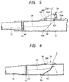
- Fig. 5 shows a fourth embodiment of the main portions of a fishing rod according to the invention.
- a fishline introduction guide 24 is similar in structure to that shown in Fig. 2, a middle rod 12 includes a plug member 41 mounted to the rear end portion thereof, and a guide ring 46' formed of ceramics is mounted on the rear end of the plug member 41.
- a base rod 10 includes a hole 10H having such an inclined shape as shown in Fig. 5 and also having a large transverse width, which hole 10H is formed at a position just behind a ceramics guide ring 38 defining an opening 38K formed in the fishline introduction guide 24.
- a plate-shaped guide member 56 such as a plate spring or the like which can be restorably flexed.
- the leading end of the plate-shaped guide member 56 can be brought into contact with a positioning portion 10B which is situated in front of the hole 10H and is formed on the inner peripheral surface of the base rod 10 on the opposite side to the opening 38K.
- a fishline insertion member 25 which is inserted from the leading end of a top rod, is contacted with a portion of the guide member 56 in the central portion of a base rod interior space and is turned toward the opening 38K by the guide member 56, and a line catch portion 25A of the fishline insertion member 25 is moved externally of the base rod 10, so that the fishline can be inserted into the fishing rod easily with the fishline insertion member 25.
- a knob portion 56A provided in the trailing and portion of the guide member 56 is pulled to remove the guide member 56 in a direction of an arrow shown in Fig. 5, then the middle rod 12 can be stored into the base rod 10.
- the guide member 56 can be inserted into the hole 10H again.
- the number of the guide member 56 is not limited to one but, alternatively, a plurality of guide members may be used, that is, they may be spread around the central portion of the interior of the base rod through which the fishline insertion member passes, thereby being able to close the interior of the base rod widely.
- Fig. 6 shows a fifth embodiment of the main portions of a fishing rod according to the invention.
- a fishline introduction guide 24 is similar in structure to that shown in Fig. 3.
- a guide member 60 which consists of a plate spring having such a side surface shape as shown in Fig. 6, by means of a fixing member 58 in such a manner that the guide member 60 is inclined.
- the fishline insertion operation can be performed easily.
- the guide member 60 When storing the fishing rod, if the middle rod 12 is pushed backwardly into the base rod, then the guide member 60 is elastically fallen down in an arrow direction and also the area of the base rod 10 where the guide member 60 is fallen is larger in diameter than the leading portion of the base rod 10. Due to this, the guide member 60 provides no obstacle to storage of the middle rod 12 and thus the middle rod 12 can be stored into the rear portion of the base rod 10.
- the guide member 60 can return back to the state shown in Fig. 6 due to its own restoring force and this state does not interfere at all with the fishline during fishing.
- Fig. 7 shows a sixth embodiment of the main portions of a fishing rod according to the invention.
- a fishline introduction guide 24 is similar in structure to that shown in Fig. 3.
- an intermediate portion of a draw-out member 62 which includes a leading end portion wide in the right and left direction of the base rod (in Fig. 7, it is drawn wide in the longitudinal direction only for the convenience of clearly showing the shape of the leading end portion) and also includes a catch portion 62A, is mounted in a hole portion 10B formed at a given position in such a manner that the draw-out member 62 can be rotated about a pin member 64.
- the draw-out member 62 is retreated in a state shown by a two-dot chained line and, when the fishline insertion member is inserted from the leading end of the top rod, the intermediate portion of the fishline insertion member is secured to the catch portion 62A of the draw-out member 62 by rotating the lever portion 62L and the fishline insertion member is then pushed out into the opening 38K. In this manner, the fishline insertion operation can be executed easily.
- the draw-out member 62 When storing the middle rod 12, since the portion of the base rod 10 extending backwardly of the neighborhood of the hole portion 10B is formed larger in diameter than the jointed portion of the leading end portion of the base rod 10, the draw-out member 62 does not interfere with the storage of the middle rod 12 while the draw-out member 62 is retreated. Also, when the middle rod 12 is drawn out for fishing, the draw-out member 62 provides no inconvenience to the draw-out operation of the middle rod 12 if the draw-out member 62 is retreated. Further, it is preferable that the lever 62L may be held by proper means so that the lever 62L can be prevented against rotation during fishing.
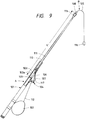
- FIGs. 9 to 14 show a seventh embodiment of the present invention.
- An intra-line fishing rod A comprises a plurality of rods which are jointed to one another in a telescopic manner, that is, a base rod 101, a middle rod 110 disposed in front of the base rod 101, and a top rod 111 disposed in front of the middle rod 110 are jointed to one another in this order (see Fig. 11).
- the outer periphery of the joint portion of the middle rod 110 is formed in a tapered manner and is removably jointed to the inner periphery of the joint portion of the base rod 101, while the outer periphery of the joint portion of the top rod 111 is similarly formed in a tapered manner and is removably jointed to the inner periphery of the joint portion of the middle rod 110.
- a line insertion tool B is inserted at first from the leading end of fishline guide 113 mounted on the top rod 111.
- Each of the respective rods 101, 110 and 111 is structured ouch that, a prepreg sheet (not shown) cut to a tape-like rectangular shape is wound around a core metal (not shown) a proper number of times, tape is applied onto the outside of the prepreg sheet thus wound, the thus formed assembly is put into a heating furnace, and it is thermally processed into a united body according to a normal processing method.
- a woven cloth is reinforced with a high-strength fiber such as carbon fiber, glass fiber, aramide fiber, alumina fiber, Kevler fiber, or other kinds of organic or inorganic fiber, and is than impregnated with thermosetting synthetic resin such as epoxy resin, phenol resin, polyester resin or the like.
- a high-strength fiber such as carbon fiber, glass fiber, aramide fiber, alumina fiber, Kevler fiber, or other kinds of organic or inorganic fiber, and is than impregnated with thermosetting synthetic resin such as epoxy resin, phenol resin, polyester resin or the like.
- the based rod 101 includes in the side surface thereof an elongated hole 101a to which a fishline introduction guide 103 is mounted and fixed, while a fishline guide frame 104 is fixed to the portion of the outer periphery of the base rod 101 situated outside the fishline introduction guide 103.
- the fishline introduction guide 103 is formed of hard material such as metal, ceramics or the like.
- the fishline introduction guide 103 defines in the central portion thereof a fishline guide hole 103a consisting of an elongated hole having a broad width and long in the axial direction of the base rod 101. Also, the fishline introduction guide 103 further includes on one side of the outside thereof a U-shaped recessed portion 103b into which the edge of the elongated hole 101a of the base rod 101 can be fitted.
- the inside 103c of the fishline introduction guide 103 is formed such that it is substantially flush with the inside surface 101b of the base rod 101 or it is situated radially outside with respect to the base rod inside surface 101b.
- the outside 103d of the fishline guide hole 103a of the fishline introduction guide 103 is formed open.
- the fishline guide frame 104 includes in the central portion thereof a through hole 104a as best shown in Fig. 12, into which the fishline introduction guide 103 can be fitted, and it also includes on one side thereof a stand-up portion 104b as best shown in Fig. 11, to which is fixed a fishline guide 114 formed of hard material such as metal, ceramics or the like.
- the fishline guide frame 104 includes a flange portion 104c on the one side thereof, a through hole is formed in the flange portion 104c, and the flange portion 104c is fixed to the base rod 101 by a fixing pin 115 fitted into the through hole.
- the fishline guide frame 104 includes on the other side thereof another flange portion 104d which can be fixed to the outer periphery of the base rod 101 by use of a string or the like not shown in the drawing.
- a fishline securing member 107 is mounted to one end of a line strip main body 105 through a flexible portion 106, a fixing member 116 is fixed to the other end of the line strip main body 105, and a stop member 108 is fitted with the other end of the line strip main body 105 where the fixing member 116 is fixed in such a manner that the stop member 108 can be stopped at a position properly distant away from the fishline securing member 107.
- the line strip main body 105 can be easily and flexibly formed by coating the outer periphery of a stainless steel wire with resin.
- the flexible portion 106 is formed in such a manner that a plurality of metal rings are connected together and can be freely flexed by the weight of the fishline securing member 107.
- the flexible portion 106 is made of material the specific gravity of which is 2 or more, preferably 4 or more.
- the flexible portion 106 may be made of the same material as that of the line strip main body 105, such as stainless steel.
- a fishline catch portion 117 formed of a string is fixed to the fishline securing member 107.
- the stop member 108 is formed of synthetic resin into a ring with a through hole 108a to which an elastic support member 118 with a through hole is filled.
- the middle rod 110 is drawn out from the base rod 101 while the top rod 111 is stored in the middle rod 110 as shown in Fig. 9.
- the stop member 108 is moved on the line strip main body 105 so that a length L from the fishline catch portion 117 of the line insertion tool B is set substantially equal to a length L' from the leading end of the fishline guide 113 of the top rod 111 to the reel (102) side of the fishline guide hole 103a of the fishline introduction guide 103.
- the fishline insertion tool B After the line insertion tool B is prepared in the above-described manner, if the fishline securing member 107 of the line insertion tool B is inserted into the fishing rod from the lending end of the fishline guide 113 of the top rod 111, then the fishline insertion tool B drops down inside the fishing due to the weight of the fishline securing member and the stop member 108 is contacted with the leading end of the fishline guide 113.
- the fishline securing member 107 is situated at the position of the fishline guide hole 103a of the fishline introduction guide 103. And, if the intra-line fishing rod A is inclined, the flexible portion 106 is flexed due to the weight of the fishline securing member 107 so that the fishline securing member 107 and fishline catch portion 117 are projected out externally from the fishline guide hole 103a of the fishline introduction guide 103.
- the middle rod 110 is drawn out from the base rod 101 while the reel side of the fishing rod A is put downward with the rod top side thereof facing upward and the top rod 111 is stored in the middle rod 110.
- the line insertion tool B drops down inside the fishing rod due to the weight of the fishline securing member 107 and the flexible portion 106 is fixed due to the weight of the fishline securing member 107, so that the fishline securing member 107 and fishline catch portion 117 are projected out externally from the fishline guide hole 103a of the fishline introduction guide 103. Due to this, the fishline 112 can be connected to the fishline catch portion 117 very easily. Also, by drawing out the fishline insertion tool B from inside the fishing rod, it is simple and easy to guide the fishline inside the fishing rod.
- the length L of the line insertion tool B from the fishline catch portion 117 to the stop member 108 can be changed by moving the stop member 108 according to the length L' from the leading end of the fishline guide 113 of the top rod 111 to the fishline guide hole 103a of the fishline introduction guide 103.
- the line insertion tool B Since the line insertion tool B is inserted through the intra-line fishing rod A while the reel (102) side of the rod faces downward and the top side of the rod faces upward, the top rod 111 is prevented from projecting out of the fishing rod A. Also, because the heavy reel mounting side of the fishing rod A is set lower than the rod top side thereof, the line insertion tool B can be inserted stably and the top rod 111 is prevented from projecting out and being broken.
- the inside 103c of the fishline introduction guide 103 is formed to be substantially flush with the rod inside surface 101b or to be situated outside the rod inside surface 101b, when the line insertion tool B is inserted through the fishing rod A, the flexible portion 106 and fishline securing member 107 are prevented from being caught on the inside 103c of the fishline introduction guide 103.
- the fishline securing member 147 and fishline catch portion 117 are easy to be projected externally from the fishline guide hole 103a of the fishline introduction guide 103.
- the intra-line fishing rod A and line insertion tool B are structured in the above-mentioned manner, if the line insertion tool B is inserted through the fishing rod A and the fishing rod A is inclined, then the line insertion tool B drops down due to the weight of the fishline securing member 107 and the flexible portion 106 is flexed due to the weight of the fishline securing member 107, so that the fishline securing member 107 and fishline catch portion 117 are projected externally from the fishline guide hole 103a of the fishline introduction guide 103. Due to this, the fishline 112 can be connected to the fishline catch portion 117 very easily and, simply by drawing out the line insertion tool B from inside the fishing rod, the fishline 112 can be guided into the fishing rod simply and easily.
- the line insertion tool B Since the line insertion tool B is inserted through the intra-line fishing rod A while the reel (102) side thereof faces downward and the rod top side thereof faces upward, the top rod 111 is prevented from projecting out of the fishing rod A. Also, because the heavy reel mounting side of the fishing rod A is set lower than the rod top side thereof, the line insertion tool B can be inserted stably and the top rod 111 is prevented from projecting out and being broken.
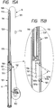
- FIG. 15A and 15B show an eighth embodiment of the invention, that is, Fig. 15A is a sectional side view of the fishing rod and Fig. 15B is a partially enlarged sectional side view of the main portions of the fishing rod shown in Fig. 15A.
- the intra-line fishing rod A comprises a plurality of rods which are jointed to one another, that is, a base rod 101, a middle rod 110 disposed in front of the base rod 101, and a top rod 111 disposed in front of the middle rod 110 are jointed to one another in this order.
- the outer periphery of the joint portion of the middle rod 110 is formed in a tapered manner and is removably jointed to the inner periphery of the joint portion of the base rod 101
- the outer periphery of the joint portion of the top rod 111 is similarly formed in a tapered manner and is removably jointed to the inner periphery of the joint portion of the middle rod 110.
- the fishline guide frame used in the seventh embodiment is omitted.
- the above-mentioned line catch portion 117 fixed to the fishline securing member 107 is formed of a string, it may be formed of metal.
- transverse hole in the fishline securing member 107 and the transverse hole may be used as a fishline catch portion.
- the flexible portion 106 may also be structured as a flexible long and narrow bar formed of rubber or the like, and the fishline catch portion side of such flexible portion may be flexed due to the weight of the flexible portion 106 itself.
- the other end of the flexible portion formed as the flexible long and narrow rubber bar may be used as the fishline securing member 107.
- transverse hole in the fishline securing member 107 consisting of the flexible portion 106 formed as the flexible long and narrow rubber bar, and the transverse hole may be used as a line catch portion.
- the fixing member 116 is fixed to the other end of the line strip main body 105 of the line insertion tool B, the fixing member may be omitted and the other end of the line strip main body 105 inserted through the stop member 108 may be folded back and retained to the stop member 108.
- telescopic type fishing rods there are shown telescopic type fishing rods but, however, there may be used a fishing rod of a joint type in which a middle rod is jointed to the front side of the base rod 101.
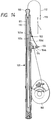
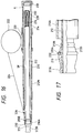
- Fig. 16 is a longitudinal section view of a fishing rod of a telescopic type according to a ninth embodiment of the invention, showing a storage state thereof, and Fig. 17 is an enlarged view of the leading end portion of the fishing rod shown in Fig. 16.
- a base rod 210 is employed as a large diameter rod and a reel mounting device 220 is disposed at a proper position in the base rod 210, while a reel 222 is mounted on the reel mounting device 220.
- a fishline introduction guide 226 which is formed of ceramics.
- a second middle rod 214 to be jointed directly to a first middle rod 212 serving as a small diameter rod is stored in the first middle rod 212
- a top rod 216 is stored in the second middle rod 214
- the first middle rod 212 is stored directly in the base rod 210.
- a hold member 230 which is formed of synthetic resin, metal, ceramics or the like and holds a guide 228 formed of ceramics, is threadedly connected to the rear end of the first middle rod 212 in a removable manner.
- the first middle rod 212 When the first middle rod 212 is stored, the first middle rod 212 is kept apart from a rod bottom part 218 connected threadedly and removably to the rear end of the base rod and is held in a hanging manner by the base rod 210 due to a structure to be described later. Also, a fishline 224, which is drawn out from the real 222, remains inserted from the rear end of the first middle rod 212 into the fishing rod and, between the outer periphery of the first middle rod 212 and the inner periphery of the base rod 210, there exists a space SP through which the fishline can be freely passed. Therefore, even if the respective rods are stored with the fishline 224 inserted through the fishing rod, the fishline 224 can be freely taken up around the reel 222 without being damaged.
- a securing main body part 213 formed of synthetic resin, aluminium alloy or the like is fixed to the outside of the leading end portion of the first middle rod 212 by means of adhesives or the like.
- the securing main body part 213 may be formed integral with the first middle rod 212, or may be formed as a separate member and then may be removably connected to the first middle rod 212, or may be fixed to the first middle rod 212 by means of adhesives as in the above-mentioned case.
- the securing main body part 213 is formed so as to have such a size that allows the securing main body part 213 to be inserted into the interior of the base rod 210.
- annular groove 213A serving as a securing portion. Therefore, if an O-ring 232 formed of elastic material is held and secured to the annular groove 213A, then the O-ring 232 abuts against the end face of the jointed portion 210A of the base rod 210 when the first middle rod 212 is stored into the base rod 210, and the first middle rod 212 is held in the hanging manner since the length of the first middle rod 212 extending from the position of the O-ring 232 to the rear end of the first middle rod 212 is set shorter than the depth of the base rod 210, so that there is produced a space K in the rear portion of the base rod 210 as shown in Fig. 16.
- first middle rod 212 and the like In order to clean the first middle rod 212 and the like or in order to perform other kinds of maintenance on the first middle rod 212 and the like, it is necessary to remove the rod bottom part 218 from the base rod 210 and then to take out the first middle rod 212 from the rear portion of the base rod 210. In this case, if the O-ring 232 is removed from the annular groove 213A, then the first middle rod 212 can be taken out from the rear portion of the base rod 210.
- the annular member is provisionally held in an annular groove 213B which is formed on the outer periphery of the securing main body part 213 and in the rear of the annular groove 213A and, in this state, the first middle rod 212 is taken out backwardly from the base rod 210.
- the outside diameter of the annular groove 213B is set smaller than the outside diameter of the annular groove 213A and, if the O-ring 232 is provisionally held in the annular groove 213B, then the first middle rod 212, as it is, can be inserted through the base rod 210.
- the reason why the provisionally holding annular groove 213B is formed in the rear of the annular groove 213A is that, during the course of moving the O-ring 232 forwardly, the O-ring 232 is likely to jump away due to its elasticity and may be lost. Also, to facilitate the movement of the O-ring 232 in the backward direction, the rear wall of the annular groove 213A is formed low in height so that the O-ring 232 can climb over the annular groove 213A easily.
- the first middle rod 212 when the first middle rod 212 is drawn out again from the base rod 210 after it is stored in the base rod 210, to facilitate the draw-out operation of the first middle rod 212, there is provided a finger securing portion 213K in the front portion of the securing main body part 213.
- the first middle rod 212 since the first middle rod 212 is not held although it is hung by the O-ring 232, if the base rod 210 with the first middle rod 212 stored therein is inclined downwardly, then the first middle rod 212 can be easily taken out from the base rod 210.
- an upper cap may be mounted on the leading end portion of the fishing rod in the storage state.
- the securing main body part 213 may be structured such that the rear portion 213S of the annular groove 213A is lightly pressed against the inner surface of the base rod joint portion 210A.
- it may be further modified such that: when the first middle rod 212 is stored, the O-ring 232 is contacted with the leading end of the base rod 210 to act as a stopper and also the first middle rod 212 is held by the light pressure of the rear portion 213S, so that, even if the first middle rod 212 drops down into the base rod 210 when it is stored, the dropping shocks of the first middle rod 212 can be buffered not only by the light pressure of the rear portion 213S but also by the elastic action of the annular member or the O-ring 232.
- the outside diameter of the annular groove 213B is adjusted and set in such a manner that, when the O-ring 232 is provisionally held in the annular groove 213B, the first middle rod 212 can be stored into the base rod 210 with the O-ring 232 be lightly contacted with the inner surface of the base rod 210, then the first middle rod 212 can be held and, in a range where the inside diameter of the base rod 210 is almost constant, the first middle rod 212 can be held at an arbitrary position with respect to the base rod 210 with a light holding force. Therefore, a fishing operation can be performed while the first middle rod 212 is held at such arbitrary position, which is convenient to adjust the length of the fishing rod.
- the first middle rod 212 is stored in the base rod 210 while it is lightly pressed against the inner surface of the base rod 210 in the above-mentioned manner in addition to the operation of the rear portion 13S, then, while the fishing rod is being carried, the first middle rod 212 is prevented from being rotated within the base rod, and the fishline 224 is prevented from twining around the first middle rod 212, so that the first middle rod 212 can be drawn out smoothly afterwards.
- the base rod 210 is used as a large diameter rod and the first middle rod 212 as a small diameter rod, when a fishline introduction guide is provided in a first middle rod 212, the present invention can also be applied to a structure in which the first middle rod 212 is used as a large diameter rod and the second middle rod 214 is used as a small diameter rod.
- the securing main body part 213 is disposed in the leading end of the first middle rod 212, the securing main body part 213 can also be disposed at a position in the intermediate portion of the first middle rod 212.
- Fig. 18 shows a tenth embodiment of a fishing rod of a telescopic type according to the invention.
- This fishing rod is not limited to the intra-line fishing rod, but it may be a fishing rod with an externally extending fishline or may be a fishing rod of a type that a fishline is connected to the leading end of the fishing rod.
- the present fishing rod may be preferably applied especially to a fishing rod such as a mountain stream fishing rod which often requires the adjustment of the length thereof. That is, a first middle rod 212 is stored in a base rod 210 in such a manner that the former can be jointed directly to the latter. Also, the first middle rod 212 includes two securing main body parts 213' respectively provided in the leading end portion thereof and in the intermediate portion thereof.
- the first middle rod 212 includes a joint portion 212A provided in the rear portion thereof.
- the two securing main body parts 213' respectively include annular grooves 213A' serving as securing portions, on which an elastically expandable and contractible annular member such as the above-mentioned O-ring 232 or the like can be secured and held.
- an elastically expandable and contractible annular member such as the above-mentioned O-ring 232 or the like can be secured and held.
- the rear outer peripheral portions 213T' of the securing main body parts 213' behind the annular grooves 213A' form pressure portions which, when the first middle rod 212 is stored, are pressed against the leading end inner surfaces 210T of the joint portions 210A of the base rod 210 with such a light pressing force that the first middle rod 212 can be drawn out.
- the joint portion 212A of the first middle rod 212 not only plays the role of a guide portion when the first middle rod 212 is stored in the range where the inside diameter of the base rod 210 is almost constant, but also, when the rear outer peripheral portion 213T' of the securing main part 213' is pressed against the leading end inner surface 210T of the base rod 210, cooperates together with the thus pressed portion to prevent the first middle rod 212 against vibration further effectively. Therefore, the length of the fishing rod can be adjusted or reduced accurately and, in the thus adjusted state, the vibration of the fishing rod can be prevented, thereby being able to stabilize a fishing operation.
- the vibration of the first middle rod 212 can be prevented.
- the first middle rod 212 can be taken out from the rear portion of the base rod 210 against the above-mentioned light pressure. In this manner, maintenance such as cleaning and the like can be performed on the first middle rod 212 easily.
- the securing main body parts 213' are disposed at two positions and thus, if the annular member 232 is moved to the annular groove 213A' formed in the front portion of the first middle rod 212 and the first middle rod 212 is stored down to this position, then the length of the fishing rod can be shortened further. This makes it possible to increase the freedom of the adjustment of the rod length. Accordingly, if the securing main body parts 213' are disposed at three or more positions, then the freedom of the adjustment of the rod length can be expanded still further.
- the annular member there may be used a metal ring which is slitted.
- the second middle rod can be used as a small diameter rod, while the first middle rod can be used as a large diameter rod.
- the annular member of the securing main body part serves as a stopper, the small diameter rod is held in the hanging manner and thus the small diameter rod can be stored without damaging the fishline. Also, due to the elasticity of the annular member, the annular member can be removed or moved, which makes it possible to take out the small diameter rod from the rear portion of the large diameter rod. That is, according to the invention, it is possible to provide a fishing rod of a telescopic type which is easy to care for.
- the fishing rod can be improved in oparationability. Also, due to the elasticity of the annular member, the annular member can be removed or moved, which allows the small diameter rod to be taken out from the rear portion of the large diameter rod, thereby being able to provide a fishing rod of a telescopic type which is easy to care for.
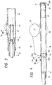
- Fig. 19 is a section view of an eleventh embodiment according to the invention, showing an intra-line fishing rod of a telescopic type for boat fishing.
- a first middle rod 312 serving as a small diameter rod is stored directly in a base rod 310 serving as a large diameter rod.
- a second middle rod (not shown) is stored in the first middle rod 312, while a top rod (not shown) is stored in the second middle rod.
- a top guide 316 is mounted on the top rod.
- a device 320 for fixing a reel 322 is disposed in the rear portion of the base rod 310, while a fishline introduction guide 318 formed in an elongated hole shape is provided in the front portion of the base rod 310.
- a cylindrical element 326 which is provided on and fixed to the inside of a bottom plug 324 to be applied to the abdomen portion of an angler during fishing, is threadedly mounted on the inner surface of the rear end portion 310K of the base rod 310.
- the cylindrical element 326 has a given length (depth), for example, a length of the order of 3 cm - 10 cm and also includes a leading end which is formed as an inclined surface 326K. As shown in Fig.
- the cylindrical element 326 is mounted in such a manner that the short side thereof is situated on the side of the fishline introduction guide 318 of the base rod.
- the fishline is allowed to pass through a space between the rear end of the first middle rod 312 and the inclined surface 326K of the cylindrical element 326 to the fishline introduction guide 318, and then the fishline can be wound by the reel 322.
- Reference character 332 designates a line insertion tool which includes a leading end portion 328.
- the leading end portion 328 is formed heavy and sturdy and, if the leading end portion 328 is bent, then it is impossible to insert the fishline through the fishing rod.
- a globular adjusting member 330 After the length of the line insertion tool 332 is adjusted to a given length by a globular adjusting member 330, if the line insertion tool 332 is inserted from the top guide 316 mounted on the leading end of the fishing rod stored in a short state, then the leading end portion 328 coming out of the rear end of the first middle rod 312 abutting against the end of the longer side of the cylindrical element 326 is stored within the cylindrical element 326 of the given length in such a manner that it hangs in the air, so that the leading end portion 328 is prevented against damage.
- the leading end portion 328 can be protected due to the existence of the cylindrical element 326, that is, the leading end portion 328 is prevented against damage.
- Fig. 19 shows a state of the fishing rod prior to execution of the line insertion operation and, in this state, the line insertion tool 332 is adjusted to such a length that the leading end of the leading end portion 328 thereof faces the fishline introduction guide 318 when the first middle rod 312 is drawn out and is then jointed to the base rod 310. Accordingly, if the fishline introduction guide (318) side of the fishing rod is turned downward, then the leading end portion 328 is allowed to hang down and move down out of the fishline introduction guide (elongated hole) 318 due to its own weight. Therefore, the fishline can be secured to the leading end line catch portion 328K and the line insertion operation is possible. During this operation as well, even if the first middle rod 312 drops down inadvertently, the leading and portion 328 can be protected due to the presence of the cylindrical element 326.
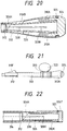
- FIG. 20 is a longitudinal section view of the main portions of a twelfth embodiment of an intra-line fishing rod of a telescopic type for casting according to the invention.
- a base rod 310 includes a rear end portion 310K on which a bottom plug 324 is threadedly mounted with an O-ring 325 between them for the purpose of waterproofing.
- An annular support member 310A is fixed integrally to the inner surface of the rear end portion 310K, while an auxiliary support portion 10B is formed in front of the annular support member 310A.
- a cylindrical element 326 having a given length extends from the inner surface of the bottom plug 324 while the cylindrical element 326 is supported by the two support members 310A and 310B.
- the present embodiment is different from the eleventh embodiment shown in Fig. 19 in that the cylindrical element 326 is not fixed to the bottom plug 324, only the bottom plug 324 can be removed, and thus, after the bottom plug 324 is removed, the cylindrical element 326 can be taken out or inserted into the fishing rod by hand.
- the leading end of the cylindrical element 326 is formed to define an inclined surface 326K, while the rear end of the first middle rod 312 can be caught by the long side (the lower side in Fig. 20) of the cylindrical element 326.
- Fig. 21 is a side view of a thirteenth embodiment of an intra-line fishing rod of a telescopic type according to the invention.
- a fishline introduction guide 318' is disposed in the front portion of a first middle rod 312 and, therefore, as shown by an enlarged section view in Fig. 22, a cylindrical element 326 is mounted on the rear end portion 312K of the first middle rot 312.
- reference character 326T stands for the bottom wall of the cylindrical element 326 and the bottom wall 326T is threadedly mounted on the first middle rod 312 with an O-ring 325 interposed therebetween.
- the cylindrical element 326 includes an inclined surface 326K and receives the rear end of a second middle rod 314 to be stored directly into the first middle rod 312.
- the cylindrical element 326 employed in each of the illustrated embodiments is not always necessary to have the inclined surface 326K, and may be designed to provide difference in height (depth) to partially contact with the rod rear end. Therefore, the inclined surface 326K may be replaced with a stepped surface.
- the element 326 in each of the embodiments should not be restricted to a cylindrical form, and may be designed, for instance, to have a plate shape as long as it defines a space between the rear ends of the rods for storing the leading end portion 328 for the purpose of protection.
- a bottom plug 324 is threadedly mounted on the rear end portion of the base rod 310. After the bottom plug 324 is removed, the cylindrical element 326 can be taken out from the rear end of the first middle rod 312 or can be inserted into the first middle rod 312 from the rear end thereof.
- a hook-shaped draw-out member on which the fishline insertion member can be caught, may be stored in the interior of the bottom plug or in an upper plug and then may be carried to a fishing spot, where the draw-out member may be taken out from its stored position when the fishline insertion operation is performed.
- a fishing rod may be structured such that a large fishhook can be stored in the bottom plug or the like, and the fishhook may be used for insertion of a fishline.
- the opening of the fishline introduction guide may be formed as an elongated hole having a width of the order of 10 mm or larger and the rod wall on the opposite side to the opening may be opened so as to face the opening.
Landscapes
- Life Sciences & Earth Sciences (AREA)
- Environmental Sciences (AREA)
- Marine Sciences & Fisheries (AREA)
- Animal Husbandry (AREA)
- Biodiversity & Conservation Biology (AREA)
- Fishing Rods (AREA)
Abstract
Description
- The present invention relates to a structure for a fishing rod, particularly applicable to a telescopic type intra-line fishing rod to facilitate the fishline insertion operation.
- In Japanese Utility Model Kokoku Publication No. Hei. 2-16626, there is disclosed a structure in which a stopper is fixed at a position corresponding to a fishline insertion hole formed in a base rod and, in the stopper, there is formed a slit-like guide groove in communication with the fishline insertion hole, whereby the fishline can be inserted from the fishline insertion hole to the rear end of a top rod in contact with the stopper.
- However, an angler can manage to carry a fishing rod in a long state but only when the angler fishes in a fishing spot near the storage place of the fishing rod, that is, in a fishing spot near the angler's house. And, generally, a fishing spot is remote from the storage place of the fishing rod and thus the fishing rod must be carried in a short state to the fishing spot by hand or by a car. Therefore, if the stopper is fixed within the base rod as in the above-mentioned conventional structure, and also if the fishing rod is of a telescopic type or telescopic type, a middle rod cannot be stored deeply into the base rod and thus the fishing rod remains long in the storage dimension thereof, which is inconvenient to carry. That is, it is difficult to carry the fishing rod to a far-off fishing spot.
- In view of the above, it is an object of the invention to provide an intra-line fishing rod which can be stored in a short size and can facilitate the insertion of a fishline.
- Another object of the invention is to provide an intra-line fishing rod which can be set easily from a short state to a long state or vice versa.
- Yet another object of the invention is to provide an intra-line fishing rod which can be stored in a short state with a fishline being inserted therethrough.
- In order to attain the above-noted and other objects, the invention provides an intra-line fishing rod comprising: a large diameter rod having a fishline introduction opening through which a fishline from a fishing reel is insertable into an interior of the large diameter rod; a small diameter rod having a rear end, the small diameter rod being coupled to the large diameter rod, and insertable into the large diameter rod backwardly beyond the fishline introduction opening; and a guide member capable of defining a guide surface substantially connecting an opening formed in the rear end of the small diameter rod to the fishline introduction opening when the small diameter rod is pulled out from the large diameter rod so that the rear end is located in the vicinity of the fishline introduction opening.
- An intra-line fishing rod of a telescopic type according to a preferred embodiment of the invention comprises a large diameter rod including at least an openable fishline introduction opening and a small diameter rod to be directly jointed to the large diameter rod in a swing-out or telescopic manner and the small diameter rod can be stored deep into the rear portion of the large diameter rod, wherein a guide member is disposed in the rear end portion of the small diameter rod, an opening is formed in the side portion of the guide member, which is in communication with a space of the interior of the small diameter rod through a communication space, and a wall surface defining the communication space includes a surface which changes its direction from the longitudinal direction of the small diameter rod to the lateral direction thereof so as to be able to guide a fishline insertion member therealong.
- In this specification, the term "a fishing rod of a telescopic type" means that a joint relation between a large diameter rod including a fishline introduction opening and a small diameter rod to be jointed to the large diameter rod satisfies a telescopic joint relation. That is, the remaining portions may be jointed together in an ordinary joint manner other than the telescopic manner. Also, the term "a fishline insertion member" used herein can also be considered as a fishline itself.
- In the embodiment, the guide member is disposed in the rear end portion of the small diameter rod, an opening is formed in the side surface of the guide member, the opening is in communication with the interior space of the small diameter rod, and the wall surface defining the above communication space includes the surface which changes its direction from the longitudinal direction of the small diameter rod to the lateral direction thereof. Due to this, after the fishline insertion member is inserted into the fishing rod, it is guided by the direction changing surface to change its direction and then it is drawn out through the fishline introduction opening, that is, the fishline insertion operation can be carried out easily. Also, the small diameter rod can be stored into the rear portion of the large diameter rod, so that the fishing rod can be kept in a short size when it is stored.
- An intra-line fishing rod of a telescopic type according to another preferred embodiment comprises a large diameter rod including at least an openable fishline introduction opening and a small diameter rod to be directly jointed to the large diameter rod in a telescopic manner and the small diameter rod can be stored into the rear portion of the large diameter rod, wherein a flexible cylindrical guide member is disposed in the rear end portion of the small diameter rod, and the interior space of the guide member is in communication with the interior space of the small diameter rod.
- Since the flexible cylindrical guide member is disposed in the rear and portion of the small diameter rod and the interior space of the guide member is in communication with the interior space of the small diameter rod, if the cylindrical guide member is flexed by pulling it, then the cylindrical guide member can be drawn out from the fishline introduction opening or can be made to face the same, the inserted fishline insertion member can be guided by the cylindrical guide member and thus can be drawn out externally through the fishline introduction opening, thereby being able to facilitate the insertion of the fishline. Also, the small diameter rod can be stored into the rear portion of the large diameter rod, thereby being able to reduce the storage dimension of the present fishing rod.
- An intra-line fishing rod of a telescopic type according to another preferred embodiment comprises a large diameter rod including at least an openable fishline introduction opening and a small diameter rod to be directly jointed to the large diameter rod in a telescopic manner and the small diameter rod can be stored into the rear portion of the large diameter rod, wherein a guide member capable of changing the direction of a fishline insertion member from the longitudinal direction of the large diameter rod to the lateral direction thereof is disposed or can be disposed in the portion of the large diameter rod situated adjacent to the fishline introduction opening, and the guide member can be freely moved out externally of the small diameter rod passing area of the large diameter rod interior space when the small diameter rod is stored.
- Since the guide member capable of changing the direction of the fishline insertion member from the longitudinal direction of the large diameter rod to the lateral direction thereof is disposed in the portion of the large diameter rod situated adjacent to the fishline introduction opening, the fishline can be inserted easily. Also, because the guide member can be freely moved externally of the small diameter passing area of the large diameter rod interior space when the small diameter rod is stored, the small diameter rod can be stored and thus the storage dimension of the present fishing rod can be reduced.
- An intra-line fishing rod of a telescopic type according to another preferred embodiment comprises a large diameter rod including at least an openable fishline introduction opening and a small diameter rod to be directly jointed to the large diameter rod in a telescopic manner and the small diameter rod can be stored into the rear portion of the large diameter rod, the fishing rod further including a draw-out member which can be operated from outside to draw out a fishline insertion member through the fishline introduction opening.
- Since the present fishing rod includes the draw-out member which can be operated from outside to draw out the fishline insertion member through the fishline introduction opening, the fishline insertion operation can be performed easily. Also, the small diameter rod ca be stored into the rear portion of the large diameter rod, which can reduce the storage dimension of the present fishing rod.
- The invention further provides a fishing rod comprising: a large diameter rod; a small diameter rod coupled to the large diameter rod; and a stopper member provided on one of the large diameter rod and the small diameter rod, wherein the small diameter rod is insertable into the large diameter rod until the stopper member is brought into contact with the other of the large diameter rod and the small diameter rod, to thereby ensure a longitudinal space between rear ends of the small and large diameter rods within an interior of the large diameter rod.
- A fishing rod of a telescopic type according to another preferred embodiment of the invention comprises: an annular member which can be expanded and contracted elastically; and, a securing portion formed in a small diameter rod to be jointed directly to a large diameter rod in a swing-out or telescopic manner, formed on the outer periphery of a securing main body having such a size as to allow said securing main body to be inserted through the large diameter rod, capable of holding the annular member, having such an outside diameter that the annular member held by the securing part can be caught on the leading end of the large diameter rod, and located at such a position that the length of the small diameter rod extending from the position of the annular member to the rear end of the small diameter rod is shorter than the depth of the large diameter rod.
- If the elastically expandable and contractible annular member is secured and held by the securing portion formed on the outer periphery of the securing main body portion provided in the small diameter rod and the small diameter is stored in the large diameter rod, then the annular member is caught on the leading end of the large diameter rod. In addition to this, since the length of the small diameter rod extending from the annular member to the rear end of the small diameter rod is shorter than the depth of the large diameter rod, there can be secured a space between the rear end of the small diameter rod and the large diameter rod. Thanks to this space, even if the small diameter rod is stored while the fishline remains inserted, there is eliminated the danger that the fishline can be crushed between the large and small diameter rods, that is, the fishline can be prevented against damage.
- Also, since the annular member can be expanded and contracted elastically, the annular member can be removed from the securing portion of the securing main body or can be moved to other positions. And, the small diameter rod with the annular member removed therefrom can be inserted through the large diameter rod, that is, it can be taken out from the rear end of the large diameter rod for maintenance such as cleaning and the like.
- A fishing rod of a telescopic type according to another preferred embodiment comprises: an annular member which can be expanded and contracted elastically; a securing portion formed in a small diameter rod to be jointed directly to a large diameter rod in a swing-out manner, formed on the outer periphery of a securing main body having such a size as to allow the securing main body to be inserted through the large diameter rod, capable of holding the annular member, and having such an outside diameter that the annular member held by the securing part can be caught on the leading end of the large diameter rod; and, a pressure portion in which, when the securing main body is situated in the leading end portion of the large diameter rod, said large and small diameter rods are pressed against each other to such an extent that the small diameter rod can be drawn out from the large diameter rod.
- If the elastically expandable and contractible annular member is secured and held by the securing portion formed on the outer periphery of the securing main body portion provided in the small diameter rod and the small diameter is stored in the large diameter rod, then the annular member is caught on the leading end of the large diameter rod, so that the storage position of the small diameter rod can be determined accurately. Also, due to provision of the pressure portion in which the large and small diameter rods are pressed against each other to such an extent that the small diameter rod can be drawn out when the small diameter rod is stored in the large diameter rod in this manner, the small diameter rod can be held with respect to the large diameter rod at a position where the annular member is caught on the leading end of the large diameter rod, so that the small diameter can be prevented against vibration. In addition to this, since the length of the fishing rod is set for a given length accurately by the positioning action of the annular member, the present fishing rod can be improved in the operationability thereof.
- Further, because the annular member can be expanded and contracted elastically, the annular member can be taken out from the securing portion of the securing main body or can be moved to other positions. Accordingly, with the annular member removed therefrom, the small diameter rod can be inserted through the large diameter rod, that is, the small diameter rod can be taken out from the rear end of the large diameter rod so as to be able to perform maintenance such as cleaning and the like on the small diameter rod.
- An intra-line fishing rod of a telescopic type according to another preferred embodiment comprises a cylindrical element which is removably disposed in the interior of the rear end portion of a large diameter rod including thereon a fishline introduction guide of intra-line fishing rod of a telescopic type, includes a space having such a length that permits storage of the front portion of a line insertion tool moving out from the rear end of a small diameter rod to be stored directly into the large diameter rod, and is able to catch the rear end of the small diameter rod.
- Since the cylindrical element is able to catch the rear end of the small diameter rod and also includes a space having such a length that permits storage of the front portion of the line insertion tool, during the line insertion operation or while a fishline with a line insertion tool attached to the leading end thereof is being wound around, even if the small diameter rod is dropped dawn inadvertently, the leading end portion of the line insertion tool can never be deformed but thus can be protected.
- The above-described features and other novel features of the invention can be understood more clearly from the following description and the accompanying drawings.
- In the accompanying drawings:
- Fig. 1 is a side view of a fishing rod according to a first embodiment of the invention;
- Fig. 2 is an enlarged longitudinal section view of the main portions of the fishing rod shown in Fig. 1;
- Fig. 3 is a longitudinal section view of the main portions of a fishing rod according to a second embodiment of the invention;
- Fig. 4 is a longitudinal section view of the main portions of a fishing rod according to a third embodiment of the invention;
- Fig. 5 is a longitudinal section view of the main portions of a fishing rod according to the fourth embodiment of the invention;
- Fig. 6 is a longitudinal section view of the main portions of a fishing rod according to a fifth embodiment of the invention;
- Fig. 7 is a longitudinal section view of the main portions of a fishing rod according to a sixth embodiment of the invention;
- Fig. 8 is a partially section view of a modification for a fishline introduction opening employed in the invention;
- Fig. 9 is a partially sectional side view of a fishing rod with a line insertion tool according to a seventh embodiment of the invention;
- Fig. 10 is a side view showing the line insertion tool in Fig. 9;
- Fig. 11 is an enlarged, longitudinally sectional view of the main portions of the fishing rod shown in Fig. 9;
- Fig. 12 is an enlarged, transverse sectional view showing the main portion of the fishing rod shown in Fig. 9;
- Fig. 13 is an enlarged plane view of the main portion of the fishing rod shown in Fig. 9;
- Fig. 14 is a partially sectional view of the main portion of the fishing rod shown in Fig. 9 after a fishline is passed therethrough;
- Fig. 15A is a longitudinally sectional view of a fishing rod according to an eighth embodiment of the invention, and Fig. 15B is an enlarged sectional view of the main portion of the fishing rod;
- Fig. 16 is a longitudinal section view of a fishing rod according to a ninth embodiment of the invention, showing a storage state;
- Fig. 17 is an enlarged section view of the front portion of the fishing rod shown in Fig. 16 in the storage state;
- Fig. 18 is a side view of a fishing rod according to a tenth embodiment of the invention.
- Fig. 19 is a section view of a fishing rod according to an eleventh embodiment of the invention;
- Fig. 20 is a section view of the main portions of a fishing rod according to a twelfth embodiment of the invention;
- Fig. 21 is a side view of a fishing rod according to a thirteenth embodiment of the invention; and,
- Fig. 22 is a section view of the main portions of the fishing rod shown in Fig. 21.
- Now, description will be given below in more detail of the embodiments of an intra-line fishing rod according to the invention with reference to the accompanying drawings.
- Fig. 1 is a side view of an intra-line fishing rod of a telescopic type according to the invention, in which a
middle rod 12 is jointed to abase rod 10 in a telescopic manner and atop rod 14 is also jointed to themiddle rod 12 in a telescopic manner. These three rods are respectively formed of a fiber reinforced resin prepreg or the like. In the rear portion of thebase rod 10, there is disposed areel fixing device 18 for fixing areel 20, while in the front portion of thebase rod 10, there is disposed a fishline introduction guide 24 through which afishline 26 drawn out from thereel 20 is introduced into the interior of the rod. Further, on the outer periphery of the leading end portion of thebase rod 10, there is disposed ametal cap 28 for the purpose of reinforcement and design, while abottom plug 22 is mounted on the rear end of thebase rod 10 through threading engagement. - In the leading end portion of the
middle rod 12, astopper 36 is mounted on a mountingmember 34 having a large diameter. Due to this, when themiddle rod 12 is stored within thebase rod 10 with thefishline 26 remaining inserted, themiddle rod 12 can be hung by the leading and portion of thebase rod 10 in order to prevent thefishline 26 from being damaged by collision of the rear end of themiddle rod 12 against the inner surface of thebottom plug 22. Here, in a featured arrangement of a first embodiment shown in Fig. 2 and a featured arrangement of a third embodiment shown in Fig. 4 (both arrangements will be described in detail later), the fishline can be protected by aguide member stopper 36 is not provided; but, however, in the other embodiments of the invention, it is preferable that thestopper 36 is provided for the purpose of protection for the fishline. Also, at a given position in the rear portion of themiddle rod 12, there is disposed arubber hold portion 30 so that themiddle rod 12 is slightly increased in the outside diameter in this portion. And, in front of thehold portion 30, there is provided aposition indication mark 32A and, if theposition indication mark 32A is set to aposition indication mark 32B provided on the cap of thebase rod 10, then themiddle rod 12 can be circumferentially aligned properly with respect to thebase rod 10. Further, thetop rod 14 includes atop guide 16 in the leading end portion thereof. - Now, Fig. 2 shows the main portions of the first embodiment shown in Fig. 1. In particular, if the
middle rod 12 is moved back to a position shown in Fig. 2 where thehold portion 30 of themiddle rod 12 is in light contact with the inner surface of the front portion of thebase rod 10 and theposition indication mark 32A is circumferentially aligned with respect to themark 32B so that the middle andbase rods opening 44K formed in the side surface of theguide member 42 is allowed to substantially face anopening 38K formed in thefishline introduction guide 24. Theguide member 42 can preferably be formed of synthetic resin or the like, and is made in threaded engagement with the rear portion of themiddle rod 12. Theopening 44K is defined by aguide ring 44 formed of ceramics, and anotherguide ring 46 formed of ceramics is disposed in a portion of theguide member 42 that communicates with the interior of themiddle rod 12. And, there is formed a communication space in theguide member 42 in such a manner that it has a curved surface 42S extending between the two guide rings 44 and 46 and varying smoothly in direction from the longitudinal direction of the middle rod to the direction oriented toward theopening 44K. Theguide member 42 in this embodiment is formed as an integral body including the threadedly engageable portion thereof. However, this is not limitative but, alternatively, theguide member 42 and the threadedly engageable portion may be structured as separate parts and, after then, they may be fixedly connected to each other or they may be removably connected to each other. Also, theguide member 42 in this embodiment is formed coaxially with respect to the axis of themiddle rod 12, but may be formed eccentric or inclined with respect to the axis of themiddle rod 12. - Also, in the front portion of the
guide member 42, that is, in the front side portion of theguide ring 46, there is formed a toprod hold portion 42B having such an inside diameter dimension as to be able to retain and hold the rear and portion of thetop rod 14. And, in the front end portion of theguide member 42, there is formed aninclined portion 42A which guides the rear end portion of thetop rod 14 to smoothly slide into the toprod hold portion 42B. - Further, the
opening 38K formed in the fishline introduction guide 24 has an elongated hole shape long in the longitudinal direction of the base rod and is defined by aguide ring 38 formed of ceramics, while the top surface of theintroduction guide 24 above theopening 38K is opened. That is, as shown in Fig. 2, twotriangular side walls 24A are respectively formed on the two sides of the elongated hole in such a manner to extend along the longitudinal direction thereof, while the top portion of the fishline introduction guide 24 above theopening 38K and between theside walls 24A is opened. Also, on the rear portion of thefishline introduction guide 24, there is provided asecond guide ring 40 which has a small diameter and is formed of ceramics. Thus, the fishline is inserted through thesecond guide ring 40, then through theopening 38K and into the interior of the fishing rod. - In advance of this fishline inserting operation, a
fishline inserting member 25 is inserted through the top end (top guide) of the rod and brought into contact with the curved surface 42S of theguide member 42 on the rear end portion of themiddle rod 12. Theline inserting member 25 is guided by the curved surface 42S and aline catch portion 25A formed in the leading end of theline inserting member 25 is guided outwardly from theopening 38K of thefishline introduction guide 24. In this manner, thefishline 26 can be caught on theline catch portion 25 and, in this state, if theline inserting member 25 is pulled from the top of the rod, then the line inserting operation of thefishline 26 can be achieved simply. - After fishing, the
middle rod 12 is stored within thebase rod 10 in a telescopic manner. In this case, as shown in Fig. 2, since the fishline introduction guide 24 is not protruded inwardly into thebase rod 10 and, in particular, the end face of theguide ring 38 on the inner side of thebase rod 10 is formed in such a manner that it is almost identical with the inner wall surface of thebase rod 10, themiddle rod 12 can be stored beyond the fishline introduction guide 24 rearwardly into thebase rod 10 and, if thestopper 36 is not provided, then themiddle rod 12 can be stored until it is contacted with thebottom plug 22. In this instance, thehold portion 30 is contacted with the leading end portion of thebase rod 10 but only slightly and, therefore, thehold portion 30 raises no inconvenience when themiddle rod 12 is stored. Themiddle rod 12 may be formed so an to have a non-circular section so that a portion of therod 12 in the circumferential direction thereof can be contacted with the inner surface of thebase rod 10. Further, it should be noted here that thehold portion 30 and position indication marks 32A, 32B are not essential to the invention. The fishline introduction guide 24 is also not limited in structure to the present embodiment as long as it has an insertion hole having such a dimension as permits the leading end portion orline catch portion 25A of the line insertion member to be guided externally of the rod. Also, if the fishline introduction guide is provided not in the base rod but in a first middle rod to be jointed to the base rod, then the first middle rod (large diameter rod) and a second middle rod (small diameter rod) to be jointed to the first middle rod are designed to have a featured arrangement shown in Fig. 2. - Also, even if the present fishing rod is stored while the
fishline 26 remains inserted, thefishline 26 is protected by theguide member 42 and is prevented from being pinched between the middle rod rear end and the bottom plug, which eliminates the danger that thefishline 26 can be held and damaged by them. In addition, in the present embodiment, since themiddle rod 12 is hung down by thestopper 36, thefishline 26 can be protected against damage. - Now, Fig. 3 shows a second embodiment of the main portions of a fishing rod according to the invention. In the second embodiment, a
plug member 41 formed of synthetic resin or the like is threadedly engaged with the rear end portion of themiddle rod 12, while aguide ring 46 formed of ceramics is disposed within theplug member 41. Similarly to the first embodiment, the portion of theplug member 41 forwardly of theguide ring 46 can retain and hold the rear end portion of thetop rod 14. A flexiblecylindrical guide member 43 formed of a coil-like spring or the like is fixed to or is removably mounted to the rear portion of themiddle rod 12 through theplug member 41, while aguide ring 44 formed of ceramics is disposed in the rear end portion of theguide member 43. Therefore, in fishing, the fishline can be guided smoothly by these guide rings 44 and 46. - The section of the
cylindrical guide member 43 may be a circular shape, an elliptic shape long in the vertical direction thereof, or other non-circular shapes. Also, thecylindrical guide member 43 may be formed of a single member or may be formed in a flexible watch band by combing together a large number of parts. - To perform a fishline insertion operation, there can be used a structure in which the
middle rod 12 is inserted into the base rod so that is set properly in position with respect to the base rod as shown in Fig. 2. However, in the second embodiment, there is employed a structure as shown in Fig. 3 in which, when the middle rod and base rod are jointed to each other in a draw-out state, a proper positional relation can be obtained between the middle rod and base rod for the fishline insertion operation. In the present structure, theguide member 43 is drawn-out as shown by two-dotted chain line in Fig. 3 with use of a fishline on hand which is made into a loop capable of catching theguide member 43 or with use of a draw-out jig. In this case, it is not always necessary to draw out theguide member 43 to a position where it projects out entirely externally, but thecylindrical guide member 43 may be flexed only to a position where a fishline insertion member and the fishline can be guided externally. In this manner, if the fishline insertion member is inserted from the leading end of the top rod, then the leading end of the fishline insertion member can be easily guided through thecylindrical guide member 43 to the outside. - Further, the end portion of the
cylindrical guide member 43, alternatively, may be formed in an inclined shape as shown by a one-dot chained line L. In this case, even if the degree of flexure of the cylindrical guide member is reduced, the end portion of the fishline insertion member can be easily guided externally. - Also, an
opening 38K is defined by aguide ring 38 formed of ceramics. Further, similarly to the first embodiment, theguide ring 38 is structured such that the end face thereof on the inner side of thebase rod 10 is almost identical with the inner wall surface of thebase rod 10 and, therefore, theguide ring 38 provides no obstacle to the storage of themiddle rod 12. In the second embodiment, theopening 38K needs a size which allows thecylindrical member 43 to be flexed and guided externally. And, it may be formed such that it is completely opened all the time, or it can be opened when the fishline is inserted while it is closed in fishing. For example, as shown in Fig. 8, one longitudinal direction end of a fishline introduction guide 24 of another type is rotatably held on thebase rod 10 by means of apivot member 76, while the other end of the fishline introduction guide 24 is held and fixed to thebase rod 10 by means of aband member 74 or the like, whereby, in the fishline insertion operation, theband member 74 is moved back and removed so that theopening 38K' can be opened, and in fishing the fishline introduction guide 24 can cover theopening 38K'. - In the present fishline introduction guide 24 shown in Fig. 8, the
opening 38K' is opened and the fishline insertion member is guided externally of theopening 38K' in the above manner, while a fishline is inserted through afishline guide tube 70 held by ahold member 72 and the fishline is then secured to the fishline insertion member, thereby carrying out a line insertion operation. After the line insertion operation is performed, the fishline introduction guide 24 is held and fixed to thebase rod 10 by means of theband member 74 or the like in such a state as shown by a solid line in Fig. 8. In the front and rear ends of the interior of thefishline guide tube 70, there are mounted two guide rings respectively formed of ceramics which can reduce the insertion resistance of the fishline. - Next, to store the middle rod, the
band member 74 is moved back again and removed, thefishline guide tube 70 is rotated and is thereby retreated together with thehold member 72 in such a manner as shown by a two-dot chained line in Fig. 8, thereby providing a space into which the middle rod can be moved back. Or, thefishline guide tube 70 may be structured in such a manner that it is slidable in the longitudinal direction with respect to thehold member 72; and, to store themiddle rod 12, thefishline guide tube 70 is slid backwardly to open the interior of thebase rod 10, thereby providing a space into which the middle rod can be moved back. - Now, Fig. 4 shows a third embodiment of the main portions of the fishing rod according to the invention. In the third embodiment, a
middle rod 12 is jointed to abase rod 10 in a draw-out state, thebase rod 10 includes a fishline introduction guide 24 similar to that shown in Fig. 3, the fishline introduction guide 24 includes aguide ring 38, and aguide member 52 is held on the rod bottom side of theguide ring 38. In the front portion of theguide member 52, there is formed acurved guide surface 52S as shown in Fig. 4. Afishline insertion member 25, which is inserted from the leading end of a top rod and is pulled out backwardly through aplug member 41 disposed in themiddle rod 12, is contacted with and curved by the above-mentionedcurved guide surface 52S so that thefishline insertion member 25 can be easily drawn out externally from anopening 38K. - The holding force for the
guide member 52 onto thebase rod 10 can be adjusted with use of an adjustingmember 54 such as a screw member or the like. After the fishline insertion operation and fishing, to store the fishing rod, themiddle rod 12 is pushed back into the rear portion of thebase rod 10. That is, in this operation, theplug member 41 of themiddle rod 12 is secured to and held by a cavity portion formed in the front portion of theguide member 52, while theguide member 52 is moved backwardly together with themiddle rod 12 to a position shown by a two-dot chained line, where it is stored. The two-dot chained line shows a state in which the middle rod 12' is secured to and held by the guide member 52'. When storing the middle rod, the adjustingmember 54 may be preferably retreated in order not only to be able to perform the storing operation smoothly but also to prevent the middle rod against damage. In Fig. 4,reference character 21 designates a rubber member which is used to absorb shocks, and 22H stands for a hole which is used to drain the water and to let the air out of the rod during the storage of the middle rod and the like. - To take out again the stored
middle rod 12, if themiddle rod 12 is drawn out, then theguide member 52 secured to and held by the rear end portion of themiddle rod 12 is drawn out together with themiddle rod 12. Here, thebase rod 10 is formed such that the portion thereof adjacent to the fishline introduction guide 54 is slightly smaller in diameter than the rear portion thereof. Thus, if the adjustingmember 54 has been screwed into thebase rod 10 by a given amount, then only theguide member 52 can be secured and held at the position of the adjustingmember 54 on the way to draw-out of themiddle rod 12. Therefore, there can be obtained such a state as shown in Fig. 4. The adjustingmember 54 is not limited to the screw member or the like but it may be structured in other manners. For example, a spring member such as a plate spring or the like having a slightly projecting shape may be provided at a similar position to the above in the inner surface of the base rod, and theguide member 52 may be held by means of the pressure of the spring member. - Now, Fig. 5 shows a fourth embodiment of the main portions of a fishing rod according to the invention. In the forth embodiment, a fishline introduction guide 24 is similar in structure to that shown in Fig. 2, a
middle rod 12 includes aplug member 41 mounted to the rear end portion thereof, and a guide ring 46' formed of ceramics is mounted on the rear end of theplug member 41. Abase rod 10 includes ahole 10H having such an inclined shape as shown in Fig. 5 and also having a large transverse width, which hole 10H is formed at a position just behind aceramics guide ring 38 defining anopening 38K formed in thefishline introduction guide 24. And, into thehole 10H, there is inserted a plate-shapedguide member 56 such as a plate spring or the like which can be restorably flexed. The leading end of the plate-shapedguide member 56 can be brought into contact with apositioning portion 10B which is situated in front of thehole 10H and is formed on the inner peripheral surface of thebase rod 10 on the opposite side to theopening 38K. - In the present structure, a
fishline insertion member 25, which is inserted from the leading end of a top rod, is contacted with a portion of theguide member 56 in the central portion of a base rod interior space and is turned toward theopening 38K by theguide member 56, and aline catch portion 25A of thefishline insertion member 25 is moved externally of thebase rod 10, so that the fishline can be inserted into the fishing rod easily with thefishline insertion member 25. To store the fishing rod, if aknob portion 56A provided in the trailing and portion of theguide member 56 is pulled to remove theguide member 56 in a direction of an arrow shown in Fig. 5, then themiddle rod 12 can be stored into thebase rod 10. To insert the fishline again, theguide member 56 can be inserted into thehole 10H again. The number of theguide member 56 is not limited to one but, alternatively, a plurality of guide members may be used, that is, they may be spread around the central portion of the interior of the base rod through which the fishline insertion member passes, thereby being able to close the interior of the base rod widely. - Now, Fig. 6 shows a fifth embodiment of the main portions of a fishing rod according to the invention. In the present embodiment, a fishline introduction guide 24 is similar in structure to that shown in Fig. 3. On the inner surface of the base rod situated opposite to the
fishline introduction guide 24, there is mounted aguide member 60, which consists of a plate spring having such a side surface shape as shown in Fig. 6, by means of a fixingmember 58 in such a manner that theguide member 60 is inclined. Afishline insertion member 25, after it is inserted from the leading end of the top rod, is contacted with theguide member 60 and, with the leading end portion thereof flexed in the lateral direction, thefishline insertion member 25 is moved out externally from anopening 38K. That is, the fishline insertion operation can be performed easily. When storing the fishing rod, if themiddle rod 12 is pushed backwardly into the base rod, then theguide member 60 is elastically fallen down in an arrow direction and also the area of thebase rod 10 where theguide member 60 is fallen is larger in diameter than the leading portion of thebase rod 10. Due to this, theguide member 60 provides no obstacle to storage of themiddle rod 12 and thus themiddle rod 12 can be stored into the rear portion of thebase rod 10. - If the
middle rod 12 is drawn out, then theguide member 60 can return back to the state shown in Fig. 6 due to its own restoring force and this state does not interfere at all with the fishline during fishing. - Now, Fig. 7 shows a sixth embodiment of the main portions of a fishing rod according to the invention. In the sixth embodiment, a fishline introduction guide 24 is similar in structure to that shown in Fig. 3. On the inner surface of the base rod situated on the opposite side to the
fishline introduction guide 24, an intermediate portion of a draw-outmember 62, which includes a leading end portion wide in the right and left direction of the base rod (in Fig. 7, it is drawn wide in the longitudinal direction only for the convenience of clearly showing the shape of the leading end portion) and also includes a catch portion 62A, is mounted in ahole portion 10B formed at a given position in such a manner that the draw-outmember 62 can be rotated about apin member 64. Normally, the draw-outmember 62 is retreated in a state shown by a two-dot chained line and, when the fishline insertion member is inserted from the leading end of the top rod, the intermediate portion of the fishline insertion member is secured to the catch portion 62A of the draw-outmember 62 by rotating thelever portion 62L and the fishline insertion member is then pushed out into theopening 38K. In this manner, the fishline insertion operation can be executed easily. - When storing the
middle rod 12, since the portion of thebase rod 10 extending backwardly of the neighborhood of thehole portion 10B is formed larger in diameter than the jointed portion of the leading end portion of thebase rod 10, the draw-outmember 62 does not interfere with the storage of themiddle rod 12 while the draw-outmember 62 is retreated. Also, when themiddle rod 12 is drawn out for fishing, the draw-outmember 62 provides no inconvenience to the draw-out operation of themiddle rod 12 if the draw-outmember 62 is retreated. Further, it is preferable that thelever 62L may be held by proper means so that thelever 62L can be prevented against rotation during fishing. - Figs. 9 to 14 show a seventh embodiment of the present invention. An intra-line fishing rod A comprises a plurality of rods which are jointed to one another in a telescopic manner, that is, a
base rod 101, amiddle rod 110 disposed in front of thebase rod 101, and atop rod 111 disposed in front of themiddle rod 110 are jointed to one another in this order (see Fig. 11). In detail, the outer periphery of the joint portion of themiddle rod 110 is formed in a tapered manner and is removably jointed to the inner periphery of the joint portion of thebase rod 101, while the outer periphery of the joint portion of thetop rod 111 is similarly formed in a tapered manner and is removably jointed to the inner periphery of the joint portion of themiddle rod 110. - When a
fishline 112 wound around a spool of areel 102 mounted on thebase rod 101 is required to be inserted into the interiors of therespective rods fishline guide 113 mounted on thetop rod 111. - Each of the
respective rods - To produce the prepreg sheet, a woven cloth is reinforced with a high-strength fiber such as carbon fiber, glass fiber, aramide fiber, alumina fiber, Kevler fiber, or other kinds of organic or inorganic fiber, and is than impregnated with thermosetting synthetic resin such as epoxy resin, phenol resin, polyester resin or the like.
- The based
rod 101 includes in the side surface thereof anelongated hole 101a to which afishline introduction guide 103 is mounted and fixed, while afishline guide frame 104 is fixed to the portion of the outer periphery of thebase rod 101 situated outside thefishline introduction guide 103. - The
fishline introduction guide 103 is formed of hard material such as metal, ceramics or the like. - The
fishline introduction guide 103 defines in the central portion thereof afishline guide hole 103a consisting of an elongated hole having a broad width and long in the axial direction of thebase rod 101. Also, thefishline introduction guide 103 further includes on one side of the outside thereof a U-shaped recessedportion 103b into which the edge of theelongated hole 101a of thebase rod 101 can be fitted. - The inside 103c of the
fishline introduction guide 103 is formed such that it is substantially flush with theinside surface 101b of thebase rod 101 or it is situated radially outside with respect to the base rod insidesurface 101b. - The outside 103d of the
fishline guide hole 103a of thefishline introduction guide 103 is formed open. - The
fishline guide frame 104 includes in the central portion thereof a throughhole 104a as best shown in Fig. 12, into which thefishline introduction guide 103 can be fitted, and it also includes on one side thereof a stand-upportion 104b as best shown in Fig. 11, to which is fixed afishline guide 114 formed of hard material such as metal, ceramics or the like. - Also, the
fishline guide frame 104 includes aflange portion 104c on the one side thereof, a through hole is formed in theflange portion 104c, and theflange portion 104c is fixed to thebase rod 101 by a fixingpin 115 fitted into the through hole. - Further, the
fishline guide frame 104 includes on the other side thereof anotherflange portion 104d which can be fixed to the outer periphery of thebase rod 101 by use of a string or the like not shown in the drawing. - Referring now to the structure of the line insertion tool B, a
fishline securing member 107 is mounted to one end of a line stripmain body 105 through aflexible portion 106, a fixingmember 116 is fixed to the other end of the line stripmain body 105, and astop member 108 is fitted with the other end of the line stripmain body 105 where the fixingmember 116 is fixed in such a manner that thestop member 108 can be stopped at a position properly distant away from thefishline securing member 107. - The line strip
main body 105 can be easily and flexibly formed by coating the outer periphery of a stainless steel wire with resin. - In the illustrated embodiment, the
flexible portion 106 is formed in such a manner that a plurality of metal rings are connected together and can be freely flexed by the weight of thefishline securing member 107. Theflexible portion 106 is made of material the specific gravity of which is 2 or more, preferably 4 or more. Theflexible portion 106 may be made of the same material as that of the line stripmain body 105, such as stainless steel. - A
fishline catch portion 117 formed of a string is fixed to thefishline securing member 107. - The
stop member 108 is formed of synthetic resin into a ring with a through hole 108a to which anelastic support member 118 with a through hole is filled. - When the line insertion tool B is inserted through the intra-line fishing rod A, the
middle rod 110 is drawn out from thebase rod 101 while thetop rod 111 is stored in themiddle rod 110 as shown in Fig. 9. - Next, the
stop member 108 is moved on the line stripmain body 105 so that a length L from thefishline catch portion 117 of the line insertion tool B is set substantially equal to a length L' from the leading end of thefishline guide 113 of thetop rod 111 to the reel (102) side of thefishline guide hole 103a of thefishline introduction guide 103. - After the line insertion tool B is prepared in the above-described manner, if the
fishline securing member 107 of the line insertion tool B is inserted into the fishing rod from the lending end of thefishline guide 113 of thetop rod 111, then the fishline insertion tool B drops down inside the fishing due to the weight of the fishline securing member and thestop member 108 is contacted with the leading end of thefishline guide 113. - If the
stop member 108 is contacted with the leading end of thefishline guide 113, then thefishline securing member 107 is situated at the position of thefishline guide hole 103a of thefishline introduction guide 103. And, if the intra-line fishing rod A is inclined, theflexible portion 106 is flexed due to the weight of thefishline securing member 107 so that thefishline securing member 107 andfishline catch portion 117 are projected out externally from thefishline guide hole 103a of thefishline introduction guide 103. - In this state, the
fishline 112 drawn out from thereel 102 is connected to thefishline catch portion 117, the line insertion tool B is pulled up and removed, andterminal tackles 119 are mounted on thefishline 112. - When the line insertion tool B is inserted into the intra-line fishing rod A, the
middle rod 110 is drawn out from thebase rod 101 while the reel side of the fishing rod A is put downward with the rod top side thereof facing upward and thetop rod 111 is stored in themiddle rod 110. And, when the line insertion tool B is inserted into the interior of the fishing rod and the fishing rod is inclined, the line insertion tool B drops down inside the fishing rod due to the weight of thefishline securing member 107 and theflexible portion 106 is fixed due to the weight of thefishline securing member 107, so that thefishline securing member 107 andfishline catch portion 117 are projected out externally from thefishline guide hole 103a of thefishline introduction guide 103. Due to this, thefishline 112 can be connected to thefishline catch portion 117 very easily. Also, by drawing out the fishline insertion tool B from inside the fishing rod, it is simple and easy to guide the fishline inside the fishing rod. - The length L of the line insertion tool B from the
fishline catch portion 117 to thestop member 108 can be changed by moving thestop member 108 according to the length L' from the leading end of thefishline guide 113 of thetop rod 111 to thefishline guide hole 103a of thefishline introduction guide 103. - Since the line insertion tool B is inserted through the intra-line fishing rod A while the reel (102) side of the rod faces downward and the top side of the rod faces upward, the
top rod 111 is prevented from projecting out of the fishing rod A. Also, because the heavy reel mounting side of the fishing rod A is set lower than the rod top side thereof, the line insertion tool B can be inserted stably and thetop rod 111 is prevented from projecting out and being broken. - Since the inside 103c of the
fishline introduction guide 103 is formed to be substantially flush with the rod insidesurface 101b or to be situated outside the rod insidesurface 101b, when the line insertion tool B is inserted through the fishing rod A, theflexible portion 106 andfishline securing member 107 are prevented from being caught on the inside 103c of thefishline introduction guide 103. - Further, because the outside 103d of the
fishline guide hole 103a of thefishline introduction guide 103 is formed open, the fishline securing member 147 andfishline catch portion 117 are easy to be projected externally from thefishline guide hole 103a of thefishline introduction guide 103. - When the intra-line fishing rod A and line insertion tool B are structured in the above-mentioned manner, if the line insertion tool B is inserted through the fishing rod A and the fishing rod A is inclined, then the line insertion tool B drops down due to the weight of the
fishline securing member 107 and theflexible portion 106 is flexed due to the weight of thefishline securing member 107, so that thefishline securing member 107 andfishline catch portion 117 are projected externally from thefishline guide hole 103a of thefishline introduction guide 103. Due to this, thefishline 112 can be connected to thefishline catch portion 117 very easily and, simply by drawing out the line insertion tool B from inside the fishing rod, thefishline 112 can be guided into the fishing rod simply and easily. - Since the line insertion tool B is inserted through the intra-line fishing rod A while the reel (102) side thereof faces downward and the rod top side thereof faces upward, the
top rod 111 is prevented from projecting out of the fishing rod A. Also, because the heavy reel mounting side of the fishing rod A is set lower than the rod top side thereof, the line insertion tool B can be inserted stably and thetop rod 111 is prevented from projecting out and being broken. - Now, Fig. 15A and 15B show an eighth embodiment of the invention, that is, Fig. 15A is a sectional side view of the fishing rod and Fig. 15B is a partially enlarged sectional side view of the main portions of the fishing rod shown in Fig. 15A.
- In the eighth embodiment, the intra-line fishing rod A comprises a plurality of rods which are jointed to one another, that is, a
base rod 101, amiddle rod 110 disposed in front of thebase rod 101, and atop rod 111 disposed in front of themiddle rod 110 are jointed to one another in this order. In detail, the outer periphery of the joint portion of themiddle rod 110 is formed in a tapered manner and is removably jointed to the inner periphery of the joint portion of thebase rod 101, while the outer periphery of the joint portion of thetop rod 111 is similarly formed in a tapered manner and is removably jointed to the inner periphery of the joint portion of themiddle rod 110. - In the eighth embodiment, the fishline guide frame used in the seventh embodiment is omitted.
- The remaining structural portions of the eighth embodiment are substantially identical with those of the seventh embodiment.
- Although the above-mentioned
line catch portion 117 fixed to thefishline securing member 107 is formed of a string, it may be formed of metal. - Alternatively, there may be opened up a transverse hole in the
fishline securing member 107 and the transverse hole may be used as a fishline catch portion. - Also, the
flexible portion 106 may also be structured as a flexible long and narrow bar formed of rubber or the like, and the fishline catch portion side of such flexible portion may be flexed due to the weight of theflexible portion 106 itself. - And, the other end of the flexible portion formed as the flexible long and narrow rubber bar may be used as the
fishline securing member 107. - Further, there may be opened a transverse hole in the
fishline securing member 107 consisting of theflexible portion 106 formed as the flexible long and narrow rubber bar, and the transverse hole may be used as a line catch portion. - In the above description, although the fixing
member 116 is fixed to the other end of the line stripmain body 105 of the line insertion tool B, the fixing member may be omitted and the other end of the line stripmain body 105 inserted through thestop member 108 may be folded back and retained to thestop member 108. - In the drawings, there are shown telescopic type fishing rods but, however, there may be used a fishing rod of a joint type in which a middle rod is jointed to the front side of the
base rod 101. - Fig. 16 is a longitudinal section view of a fishing rod of a telescopic type according to a ninth embodiment of the invention, showing a storage state thereof, and Fig. 17 is an enlarged view of the leading end portion of the fishing rod shown in Fig. 16. In the present embodiment, a
base rod 210 is employed as a large diameter rod and areel mounting device 220 is disposed at a proper position in thebase rod 210, while areel 222 is mounted on thereel mounting device 220. - Forwardly of the
reel mounting device 220 and in the neighborhood of the leading end of thebase rod 210, there is disposed afishline introduction guide 226 which is formed of ceramics. A secondmiddle rod 214 to be jointed directly to a firstmiddle rod 212 serving as a small diameter rod is stored in the firstmiddle rod 212, atop rod 216 is stored in the secondmiddle rod 214, and the firstmiddle rod 212 is stored directly in thebase rod 210. Also, ahold member 230, which is formed of synthetic resin, metal, ceramics or the like and holds aguide 228 formed of ceramics, is threadedly connected to the rear end of the firstmiddle rod 212 in a removable manner. - When the first
middle rod 212 is stored, the firstmiddle rod 212 is kept apart from a rodbottom part 218 connected threadedly and removably to the rear end of the base rod and is held in a hanging manner by thebase rod 210 due to a structure to be described later. Also, afishline 224, which is drawn out from the real 222, remains inserted from the rear end of the firstmiddle rod 212 into the fishing rod and, between the outer periphery of the firstmiddle rod 212 and the inner periphery of thebase rod 210, there exists a space SP through which the fishline can be freely passed. Therefore, even if the respective rods are stored with thefishline 224 inserted through the fishing rod, thefishline 224 can be freely taken up around thereel 222 without being damaged. - Referring now to Fig. 17, a securing
main body part 213 formed of synthetic resin, aluminium alloy or the like is fixed to the outside of the leading end portion of the firstmiddle rod 212 by means of adhesives or the like. The securingmain body part 213 may be formed integral with the firstmiddle rod 212, or may be formed as a separate member and then may be removably connected to the firstmiddle rod 212, or may be fixed to the firstmiddle rod 212 by means of adhesives as in the above-mentioned case. And, the securingmain body part 213 is formed so as to have such a size that allows the securingmain body part 213 to be inserted into the interior of thebase rod 210. Almost at the central position of the securingmain body part 213, there is formed anannular groove 213A serving as a securing portion. Therefore, if an O-ring 232 formed of elastic material is held and secured to theannular groove 213A, then the O-ring 232 abuts against the end face of the jointedportion 210A of thebase rod 210 when the firstmiddle rod 212 is stored into thebase rod 210, and the firstmiddle rod 212 is held in the hanging manner since the length of the firstmiddle rod 212 extending from the position of the O-ring 232 to the rear end of the firstmiddle rod 212 is set shorter than the depth of thebase rod 210, so that there is produced a space K in the rear portion of thebase rod 210 as shown in Fig. 16. This can eliminate the danger that thefishline 224 can be pinched and crushed between the firstmiddle rod 212 andbase rod 210. Also, since the annular member such as the O-ring 232 or the like acting as a stopper has elasticity, even if the firstmiddle rod 212 happens to drop into thebase rod 210 when it is stored, the shocks produced between the firstmiddle rod 212 and the end face of thebase rod 210 can be buffered or absorbed to thereby be able to prevent the firstmiddle rod 212 against damage. - In order to clean the first
middle rod 212 and the like or in order to perform other kinds of maintenance on the firstmiddle rod 212 and the like, it is necessary to remove the rodbottom part 218 from thebase rod 210 and then to take out the firstmiddle rod 212 from the rear portion of thebase rod 210. In this case, if the O-ring 232 is removed from theannular groove 213A, then the firstmiddle rod 212 can be taken out from the rear portion of thebase rod 210. Also, in order that the elastically expandable and contractible annular member such as the O-ring 232 or the like removed from theannular groove 213A may not be lost, the annular member is provisionally held in anannular groove 213B which is formed on the outer periphery of the securingmain body part 213 and in the rear of theannular groove 213A and, in this state, the firstmiddle rod 212 is taken out backwardly from thebase rod 210. The outside diameter of theannular groove 213B is set smaller than the outside diameter of theannular groove 213A and, if the O-ring 232 is provisionally held in theannular groove 213B, then the firstmiddle rod 212, as it is, can be inserted through thebase rod 210. The reason why the provisionally holdingannular groove 213B is formed in the rear of theannular groove 213A is that, during the course of moving the O-ring 232 forwardly, the O-ring 232 is likely to jump away due to its elasticity and may be lost. Also, to facilitate the movement of the O-ring 232 in the backward direction, the rear wall of theannular groove 213A is formed low in height so that the O-ring 232 can climb over theannular groove 213A easily. - Further, when the first
middle rod 212 is drawn out again from thebase rod 210 after it is stored in thebase rod 210, to facilitate the draw-out operation of the firstmiddle rod 212, there is provided afinger securing portion 213K in the front portion of the securingmain body part 213. However, in the present embodiment, since the firstmiddle rod 212 is not held although it is hung by the O-ring 232, if thebase rod 210 with the firstmiddle rod 212 stored therein is inclined downwardly, then the firstmiddle rod 212 can be easily taken out from thebase rod 210. On the other hand, to prevent the firstmiddle rod 212 from projecting out accidentally, an upper cap may be mounted on the leading end portion of the fishing rod in the storage state. Or, the securingmain body part 213 may be structured such that therear portion 213S of theannular groove 213A is lightly pressed against the inner surface of the base rodjoint portion 210A. In connection with this structure, it may be further modified such that: when the firstmiddle rod 212 is stored, the O-ring 232 is contacted with the leading end of thebase rod 210 to act as a stopper and also the firstmiddle rod 212 is held by the light pressure of therear portion 213S, so that, even if the firstmiddle rod 212 drops down into thebase rod 210 when it is stored, the dropping shocks of the firstmiddle rod 212 can be buffered not only by the light pressure of therear portion 213S but also by the elastic action of the annular member or the O-ring 232. - Further, if the outside diameter of the
annular groove 213B is adjusted and set in such a manner that, when the O-ring 232 is provisionally held in theannular groove 213B, the firstmiddle rod 212 can be stored into thebase rod 210 with the O-ring 232 be lightly contacted with the inner surface of thebase rod 210, then the firstmiddle rod 212 can be held and, in a range where the inside diameter of thebase rod 210 is almost constant, the firstmiddle rod 212 can be held at an arbitrary position with respect to thebase rod 210 with a light holding force. Therefore, a fishing operation can be performed while the firstmiddle rod 212 is held at such arbitrary position, which is convenient to adjust the length of the fishing rod. Moreover, if the firstmiddle rod 212 is stored in thebase rod 210 while it is lightly pressed against the inner surface of thebase rod 210 in the above-mentioned manner in addition to the operation of the rear portion 13S, then, while the fishing rod is being carried, the firstmiddle rod 212 is prevented from being rotated within the base rod, and thefishline 224 is prevented from twining around the firstmiddle rod 212, so that the firstmiddle rod 212 can be drawn out smoothly afterwards. - Instead of the O-
ring 232, there can be used a rubber annular member which can be elastically deformed in a similar manner, a metal ring such as a washer which includes a cutaway portion and also has elasticity, or the like. Also, in the above-mentioned embodiment, although thebase rod 210 is used as a large diameter rod and the firstmiddle rod 212 as a small diameter rod, when a fishline introduction guide is provided in a firstmiddle rod 212, the present invention can also be applied to a structure in which the firstmiddle rod 212 is used as a large diameter rod and the secondmiddle rod 214 is used as a small diameter rod. Further, in the above-mentioned embodiment, although the securingmain body part 213 is disposed in the leading end of the firstmiddle rod 212, the securingmain body part 213 can also be disposed at a position in the intermediate portion of the firstmiddle rod 212. - Next, Fig. 18 shows a tenth embodiment of a fishing rod of a telescopic type according to the invention. This fishing rod is not limited to the intra-line fishing rod, but it may be a fishing rod with an externally extending fishline or may be a fishing rod of a type that a fishline is connected to the leading end of the fishing rod. The present fishing rod may be preferably applied especially to a fishing rod such as a mountain stream fishing rod which often requires the adjustment of the length thereof. That is, a first
middle rod 212 is stored in abase rod 210 in such a manner that the former can be jointed directly to the latter. Also, the firstmiddle rod 212 includes two securing main body parts 213' respectively provided in the leading end portion thereof and in the intermediate portion thereof. Further, the firstmiddle rod 212 includes ajoint portion 212A provided in the rear portion thereof. Moreover, the two securing main body parts 213' respectively includeannular grooves 213A' serving as securing portions, on which an elastically expandable and contractible annular member such as the above-mentioned O-ring 232 or the like can be secured and held. When the firstmiddle rod 212 is stored, the thus secured O-ring 232 is contacted with the leading end of thebase rod 210. Due to this, the storage position of the firstmiddle rod 212 can be determined accurately and the length of the fishing rod of a telescopic type can be adjusted or reduced a given amount. - Also, the rear outer
peripheral portions 213T' of the securing main body parts 213' behind theannular grooves 213A' (O-rings 232) form pressure portions which, when the firstmiddle rod 212 is stored, are pressed against the leading endinner surfaces 210T of thejoint portions 210A of thebase rod 210 with such a light pressing force that the firstmiddle rod 212 can be drawn out. Thejoint portion 212A of the firstmiddle rod 212 not only plays the role of a guide portion when the firstmiddle rod 212 is stored in the range where the inside diameter of thebase rod 210 is almost constant, but also, when the rear outerperipheral portion 213T' of the securing main part 213' is pressed against the leading endinner surface 210T of thebase rod 210, cooperates together with the thus pressed portion to prevent the firstmiddle rod 212 against vibration further effectively. Therefore, the length of the fishing rod can be adjusted or reduced accurately and, in the thus adjusted state, the vibration of the fishing rod can be prevented, thereby being able to stabilize a fishing operation. - Also, even when only the
joint portion 212A is formed to have such an outside diameter dimension that allows thejoint portion 212A to act as the pressure portion in the range where the inside diameter of thebase rod 210 is almost constant, the vibration of the firstmiddle rod 212 can be prevented. - To take out the first
middle rod 212 from the rear portion of thebase rod 210, if the O-ring 232 is removed from theannular groove 213A' and is moved to the main body portion of the firstmiddle rod 212 situated in the rear of the securing main body part 213', then the firstmiddle rod 212 can be taken out from the rear portion of thebase rod 210 against the above-mentioned light pressure. In this manner, maintenance such as cleaning and the like can be performed on the firstmiddle rod 212 easily. - Further, in the present embodiment, the securing main body parts 213' are disposed at two positions and thus, if the
annular member 232 is moved to theannular groove 213A' formed in the front portion of the firstmiddle rod 212 and the firstmiddle rod 212 is stored down to this position, then the length of the fishing rod can be shortened further. This makes it possible to increase the freedom of the adjustment of the rod length. Accordingly, if the securing main body parts 213' are disposed at three or more positions, then the freedom of the adjustment of the rod length can be expanded still further. Similarly to the ninth embodiment shown in Figs. 16 and 17, in the present embodiment as well, there may be formed a groove in which the annular member such as the O-ring or the like can be held provisionally. Also, similarly, as the annular member, there may be used a metal ring which is slitted. Further, similarly, the second middle rod can be used as a small diameter rod, while the first middle rod can be used as a large diameter rod. - As can he seen clearly from the foregoing description, even if the small diameter rod is stored while the fishline remains inserted through the fishing rod, since the annular member of the securing main body part serves as a stopper, the small diameter rod is held in the hanging manner and thus the small diameter rod can be stored without damaging the fishline. Also, due to the elasticity of the annular member, the annular member can be removed or moved, which makes it possible to take out the small diameter rod from the rear portion of the large diameter rod. That is, according to the invention, it is possible to provide a fishing rod of a telescopic type which is easy to care for.
- Also, since the action of the annular member held in the securing portion can adjust or reduce the length of the fishing rod to a given length accurately as well as since the existence of the pressure portion prevents the fishing rod against vibration, the fishing rod can be improved in oparationability. Also, due to the elasticity of the annular member, the annular member can be removed or moved, which allows the small diameter rod to be taken out from the rear portion of the large diameter rod, thereby being able to provide a fishing rod of a telescopic type which is easy to care for.
- Fig. 19 is a section view of an eleventh embodiment according to the invention, showing an intra-line fishing rod of a telescopic type for boat fishing. A first
middle rod 312 serving as a small diameter rod is stored directly in abase rod 310 serving as a large diameter rod. A second middle rod (not shown) is stored in the firstmiddle rod 312, while a top rod (not shown) is stored in the second middle rod. Atop guide 316 is mounted on the top rod. - A
device 320 for fixing areel 322 is disposed in the rear portion of thebase rod 310, while afishline introduction guide 318 formed in an elongated hole shape is provided in the front portion of thebase rod 310. Acylindrical element 326, which is provided on and fixed to the inside of abottom plug 324 to be applied to the abdomen portion of an angler during fishing, is threadedly mounted on the inner surface of therear end portion 310K of thebase rod 310. And, thecylindrical element 326 has a given length (depth), for example, a length of the order of 3 cm - 10 cm and also includes a leading end which is formed as aninclined surface 326K. As shown in Fig. 19, thecylindrical element 326 is mounted in such a manner that the short side thereof is situated on the side of thefishline introduction guide 318 of the base rod. In this arrangement, when the respective rods are stored in such a manner as shown in Fig. 19 with the fishline remaining inserted, the fishline is allowed to pass through a space between the rear end of the firstmiddle rod 312 and theinclined surface 326K of thecylindrical element 326 to thefishline introduction guide 318, and then the fishline can be wound by thereel 322. -
Reference character 332 designates a line insertion tool which includes aleading end portion 328. Theleading end portion 328 is formed heavy and sturdy and, if theleading end portion 328 is bent, then it is impossible to insert the fishline through the fishing rod. After the length of theline insertion tool 332 is adjusted to a given length by aglobular adjusting member 330, if theline insertion tool 332 is inserted from thetop guide 316 mounted on the leading end of the fishing rod stored in a short state, then theleading end portion 328 coming out of the rear end of the firstmiddle rod 312 abutting against the end of the longer side of thecylindrical element 326 is stored within thecylindrical element 326 of the given length in such a manner that it hangs in the air, so that theleading end portion 328 is prevented against damage. Also, when the fishline is taken up around thereel 322 in such a manner that the leading end of the fishline remains secured to aline catch portion 328K formed in the leading end of theline insertion tool 332, even if the firstmiddle rod 312 is inadvertently dropped down into thebase rod 310 during operation, theleading end portion 328 can be protected due to the existence of thecylindrical element 326, that is, theleading end portion 328 is prevented against damage. - Now, Fig. 19 shows a state of the fishing rod prior to execution of the line insertion operation and, in this state, the
line insertion tool 332 is adjusted to such a length that the leading end of theleading end portion 328 thereof faces thefishline introduction guide 318 when the firstmiddle rod 312 is drawn out and is then jointed to thebase rod 310. Accordingly, if the fishline introduction guide (318) side of the fishing rod is turned downward, then theleading end portion 328 is allowed to hang down and move down out of the fishline introduction guide (elongated hole) 318 due to its own weight. Therefore, the fishline can be secured to the leading endline catch portion 328K and the line insertion operation is possible. During this operation as well, even if the firstmiddle rod 312 drops down inadvertently, the leading andportion 328 can be protected due to the presence of thecylindrical element 326. - Now, Fig. 20 is a longitudinal section view of the main portions of a twelfth embodiment of an intra-line fishing rod of a telescopic type for casting according to the invention. A
base rod 310 includes arear end portion 310K on which abottom plug 324 is threadedly mounted with an O-ring 325 between them for the purpose of waterproofing. Anannular support member 310A is fixed integrally to the inner surface of therear end portion 310K, while anauxiliary support portion 10B is formed in front of theannular support member 310A. And, acylindrical element 326 having a given length extends from the inner surface of thebottom plug 324 while thecylindrical element 326 is supported by the twosupport members cylindrical element 326 is not fixed to thebottom plug 324, only thebottom plug 324 can be removed, and thus, after thebottom plug 324 is removed, thecylindrical element 326 can be taken out or inserted into the fishing rod by hand. - The remaining structures and operations of the twelfth embodiment are similar to the embodiment shown in Fig. 19. For example, the leading end of the
cylindrical element 326 is formed to define aninclined surface 326K, while the rear end of the firstmiddle rod 312 can be caught by the long side (the lower side in Fig. 20) of thecylindrical element 326. - Now, Fig. 21 is a side view of a thirteenth embodiment of an intra-line fishing rod of a telescopic type according to the invention. In the thirteenth embodiment, a fishline introduction guide 318' is disposed in the front portion of a first
middle rod 312 and, therefore, as shown by an enlarged section view in Fig. 22, acylindrical element 326 is mounted on therear end portion 312K of the firstmiddle rot 312. In Fig. 22,reference character 326T stands for the bottom wall of thecylindrical element 326 and thebottom wall 326T is threadedly mounted on the firstmiddle rod 312 with an O-ring 325 interposed therebetween. Similarly to the previous embodiments, thecylindrical element 326 includes aninclined surface 326K and receives the rear end of a secondmiddle rod 314 to be stored directly into the firstmiddle rod 312. However, thecylindrical element 326 employed in each of the illustrated embodiments is not always necessary to have theinclined surface 326K, and may be designed to provide difference in height (depth) to partially contact with the rod rear end. Therefore, theinclined surface 326K may be replaced with a stepped surface. Similarly, theelement 326 in each of the embodiments should not be restricted to a cylindrical form, and may be designed, for instance, to have a plate shape as long as it defines a space between the rear ends of the rods for storing theleading end portion 328 for the purpose of protection. - A
bottom plug 324 is threadedly mounted on the rear end portion of thebase rod 310. After thebottom plug 324 is removed, thecylindrical element 326 can be taken out from the rear end of the firstmiddle rod 312 or can be inserted into the firstmiddle rod 312 from the rear end thereof. - Other structures can be employed in cooperation with the above-mentioned embodiments. For example, a hook-shaped draw-out member, on which the fishline insertion member can be caught, may be stored in the interior of the bottom plug or in an upper plug and then may be carried to a fishing spot, where the draw-out member may be taken out from its stored position when the fishline insertion operation is performed. Also, a fishing rod may be structured such that a large fishhook can be stored in the bottom plug or the like, and the fishhook may be used for insertion of a fishline.
- Further, the opening of the fishline introduction guide may be formed as an elongated hole having a width of the order of 10 mm or larger and the rod wall on the opposite side to the opening may be opened so as to face the opening. In this structure, if the fishline insertion member inserted from the leading end of the top rod is pressed down from one opening with a finger, then the fishline insertion member can be pushed out from the other opening, so that the fishline insertion operation can be performed easily.
Claims (19)
- An intra-line fishing rod comprising:
a large diameter rod having a fishline introduction opening through which a fishline from a fishing reel is insertable into an interior of the large diameter rod;
a small diameter rod having a rear end, the small diameter rod being coupled to the large diameter rod, and insertable into the large diameter rod backwardly beyond the fishline introduction opening; and
a guide member capable of defining a guide surface substantially connecting an opening formed in the rear end of the small diameter rod to the fishline introduction opening when the small diameter rod is pulled out from the large diameter rod so that the rear end is located in the vicinity of the fishline introduction opening. - An intra-line fishing rod according to claim 1, wherein the guide member is mounted on the rear end of the small diameter rod, the guide member having a first opening oriented to face an inner surface of the large diameter rod, a second opening communicating with an interior of the small diameter rod, and a curved wall surface extending between the first and second openings of the guide member.
- An intra-line fishing rod according to claim 1, wherein the guide member includes a flexible cylindrical member mounted to the rear end of the small diameter rod so that an interior of the flexible cylindrical member is communicated with an interior of the small diameter rod.
- An intra-line fishing rod according to claim 1, wherein the guide member is slidably mounted onto the interior of the large diameter rod.
- An intra-line fishing rod according to claim 1, wherein the guide member is removably mounted onto the large diameter rod.
- An intra-line fishing rod according to claim 1, wherein the guide member includes an elastically deformable member attached to the inner surface of the large diameter rod.
- An intra-line fishing rod according to claim 1, wherein the guide member includes a draw-out member which can be operated externally.
- An intra-line fishing rod comprising:
a large diameter rod having a fishline introduction opening through which a fishline from a fishing reel is insertable into an interior of the large diameter rod;
a small diameter rod having an opening at a rear end, the small diameter rod being coupled to the large diameter rod, and insertable into the large diameter rod backwardly; and
a pair of position markers provided on large and small diameter rods, respectively;
wherein when the small diameter rod is inserted into the interior of the large diameter rod until the position markers of the pair are aligned with each other, the opening of the small diameter rod is located in the vicinity of the fishline introduction opening. - An intra-line fishing rod according to claim 8, further comprising:
means for lightly contacting the small diameter rod with the large diameter rod when the small diameter rod is inserted into the interior of the large diameter rod until the position markers of the pair are aligned with each other, to thereby retain the small diameter rod in that position with respect to the large diameter rod. - An intra-line fishing rod according to claim 8, further comprising:
a guide member defining a guide surface substantially connecting the opening of the small diameter rod to the fishline introduction opening when the small diameter rod is inserted into the interior of the large diameter rod until the position markers of the pair are aligned with each other. - An intra-line fishing rod comprising:
a rod having an elongated hole, and
a fishline introduction guide mounted on the elongated hole to define a fishline guide hole through which a fishline from a fishing reel is insertable into an interior of the rod; and wherein:
the fishline guide hole is substantially in the form of rectangle elongated in a longitudinal direction of the rod; and
an inner side of the fishline introduction guide is made substantially flush with or disposed radially outwardly from an inner surface of the rod. - A line insertion tool for an intra-line fishing rod, comprising:
a line strip main body having a first end and a second end opposite from the first end;
a flexible portion connected to the first end;
a fishline securing member provided on the flexible portion for temporarily retaining a fishline thereon; and
a stop member provided on the line strip main body and located between the flexible portion and the second end of the line strip main body, the stop member being retained at a desired position on the line strip main body to define a variable length between the fishline securing member and the stop member. - A fishing rod comprising:
a large diameter rod;
a small diameter rod coupled to the large diameter rod; and
a stopper member provided on one of the large diameter rod and the small diameter rod, wherein
the small diameter rod is insertable into the large diameter rod until the stopper member is brought into contact with the other of the large diameter rod and the small diameter rod, to thereby ensure a longitudinal space between rear ends of the small and large diameter rods within an interior of the large diameter rod. - A fishing rod according to claim 13, wherein the stopper member is in the form of annulus and elastically expanded and contracted, the stopper member being provided on the small diameter rod.
- A fishing rod according to claim 14, wherein the stopper member is mounted on a securing portion formed on an outer periphery of the small diameter rod and projecting radially outwardly therefrom, the securing portion having such a size as to permit said securing main body to be inserted into the large diameter rod.
- A fishing rod according to claim 15, further comprising:
means for lightly contacting the small diameter rod with the large diameter rod when the small diameter rod is inserted into the interior of the large diameter rod. - A fishing rod according to claim 13, wherein the stopper member is provided on the large diameter rod and contactable with the rear end of the small diameter rod within the interior of the large diameter rod.
- A fishing rod according to claim 17, wherein the stopper member is in the form of a hollow cylinder.
- A fishing rod according to claim 18, wherein the stopper member has an inclined surface partially contactable with the rear end of the small diameter rod.
Priority Applications (1)
| Application Number | Priority Date | Filing Date | Title |
|---|---|---|---|
| EP98120849A EP0893055B1 (en) | 1994-08-12 | 1995-08-11 | Fishing rod |
Applications Claiming Priority (6)
| Application Number | Priority Date | Filing Date | Title |
|---|---|---|---|
| JP211874/94 | 1994-08-12 | ||
| JP21187494A JP2901884B2 (en) | 1994-08-12 | 1994-08-12 | Swing fishing rod |
| JP6238526A JP3027305B2 (en) | 1994-09-06 | 1994-09-06 | Swing type fishing rod |
| JP238526/94 | 1994-09-06 | ||
| JP11377395 | 1995-04-14 | ||
| JP113773/95 | 1995-04-14 |
Related Child Applications (1)
| Application Number | Title | Priority Date | Filing Date |
|---|---|---|---|
| EP98120849A Division EP0893055B1 (en) | 1994-08-12 | 1995-08-11 | Fishing rod |
Publications (3)
| Publication Number | Publication Date |
|---|---|
| EP0696421A2 true EP0696421A2 (en) | 1996-02-14 |
| EP0696421A3 EP0696421A3 (en) | 1996-05-08 |
| EP0696421B1 EP0696421B1 (en) | 1999-05-19 |
Family
ID=27312580
Family Applications (2)
| Application Number | Title | Priority Date | Filing Date |
|---|---|---|---|
| EP98120849A Expired - Lifetime EP0893055B1 (en) | 1994-08-12 | 1995-08-11 | Fishing rod |
| EP19950112697 Expired - Lifetime EP0696421B1 (en) | 1994-08-12 | 1995-08-11 | Fishing rod |
Family Applications Before (1)
| Application Number | Title | Priority Date | Filing Date |
|---|---|---|---|
| EP98120849A Expired - Lifetime EP0893055B1 (en) | 1994-08-12 | 1995-08-11 | Fishing rod |
Country Status (2)
| Country | Link |
|---|---|
| EP (2) | EP0893055B1 (en) |
| DE (2) | DE69529424T2 (en) |
Cited By (2)
| Publication number | Priority date | Publication date | Assignee | Title |
|---|---|---|---|---|
| EP0832559A2 (en) * | 1996-08-28 | 1998-04-01 | Daiwa Seiko Inc. | Telescopic type interline fishing rod |
| GB2317801A (en) * | 1993-10-08 | 1998-04-08 | Daiwa Seiko Inc | Fisfing rod |
Citations (1)
| Publication number | Priority date | Publication date | Assignee | Title |
|---|---|---|---|---|
| JPH0216626A (en) | 1988-07-05 | 1990-01-19 | Nec Corp | Printer output control system |
Family Cites Families (13)
| Publication number | Priority date | Publication date | Assignee | Title |
|---|---|---|---|---|
| US1595275A (en) * | 1924-10-04 | 1926-08-10 | Joel K White | Fishing rod |
| US2282618A (en) * | 1941-04-05 | 1942-05-12 | William H Stewart | Fishing rod |
| US2541609A (en) * | 1947-02-21 | 1951-02-13 | Pullan James Francis | Fishing rod |
| FR980938A (en) * | 1949-02-14 | 1951-05-21 | Advanced fishing rod | |
| FR92983E (en) * | 1966-06-24 | 1969-01-24 | Carabasse Andre | Universal fishing rod. |
| FR1592422A (en) * | 1968-11-20 | 1970-05-11 | ||
| FR2064581A5 (en) * | 1969-09-30 | 1971-07-23 | Vigier Roger | |
| FR2090915A5 (en) * | 1971-04-22 | 1972-01-14 | Reclus Henri | |
| US3862509A (en) * | 1973-05-30 | 1975-01-28 | Jr John W Petersen | Eyeless fishing pole |
| GB2112612A (en) * | 1981-12-31 | 1983-07-27 | Centreline Rods Limited | Line threader |
| DE3246801A1 (en) * | 1982-12-17 | 1984-06-20 | Eduard Schrankler | Line inner guide in telescopic fishing rods |
| FR2539582B1 (en) * | 1983-01-20 | 1985-07-12 | Garbolino Sa Ets | TELESCOPIC FISHING ROD WITH AN INTERNAL WIRE TO BE EQUIPPED WITH A REEL |
| JPS62181728A (en) * | 1987-01-23 | 1987-08-10 | ダイワ精工株式会社 | Method for forming pattern to fishing rod |
-
1995
- 1995-08-11 DE DE1995629424 patent/DE69529424T2/en not_active Expired - Fee Related
- 1995-08-11 DE DE1995609708 patent/DE69509708T2/en not_active Expired - Fee Related
- 1995-08-11 EP EP98120849A patent/EP0893055B1/en not_active Expired - Lifetime
- 1995-08-11 EP EP19950112697 patent/EP0696421B1/en not_active Expired - Lifetime
Patent Citations (1)
| Publication number | Priority date | Publication date | Assignee | Title |
|---|---|---|---|---|
| JPH0216626A (en) | 1988-07-05 | 1990-01-19 | Nec Corp | Printer output control system |
Cited By (4)
| Publication number | Priority date | Publication date | Assignee | Title |
|---|---|---|---|---|
| GB2317801A (en) * | 1993-10-08 | 1998-04-08 | Daiwa Seiko Inc | Fisfing rod |
| GB2317801B (en) * | 1993-10-08 | 1998-06-24 | Daiwa Seiko Inc | Inter-line fishing rod |
| EP0832559A2 (en) * | 1996-08-28 | 1998-04-01 | Daiwa Seiko Inc. | Telescopic type interline fishing rod |
| EP0832559A3 (en) * | 1996-08-28 | 1999-04-07 | Daiwa Seiko Inc. | Telescopic type interline fishing rod |
Also Published As
| Publication number | Publication date |
|---|---|
| DE69509708D1 (en) | 1999-06-24 |
| EP0893055A2 (en) | 1999-01-27 |
| EP0893055B1 (en) | 2003-01-15 |
| DE69529424D1 (en) | 2003-02-20 |
| DE69509708T2 (en) | 1999-09-23 |
| EP0893055A3 (en) | 1999-04-14 |
| DE69529424T2 (en) | 2003-06-05 |
| EP0696421B1 (en) | 1999-05-19 |
| EP0696421A3 (en) | 1996-05-08 |
Similar Documents
| Publication | Publication Date | Title |
|---|---|---|
| US8919293B2 (en) | Self-containing, retractable leash and collar/harness assembly | |
| US20190208748A1 (en) | Retractable leash and collar or harness assembly | |
| US20020178642A1 (en) | Case for a fishing rod and reel | |
| US5577338A (en) | Hollow collapsible fishing rod with fishline guide | |
| US5261627A (en) | Fishline guide mechanism for spinning reel for fishing | |
| US20120260558A1 (en) | Deep water fishing rod and electric reel | |
| GB2253982A (en) | Landing nets. | |
| US2555397A (en) | Trotline holder | |
| US4571875A (en) | Fish landing net | |
| EP0696421A2 (en) | Fishing rod | |
| US20160198688A1 (en) | Telescoping Fishing Rod Assembly | |
| US2755037A (en) | Spool construction for spinning reel | |
| US5996267A (en) | Landing net | |
| US5950346A (en) | Multi-segment fishing rod assembly | |
| US6367190B1 (en) | Fly harnessing and storage device | |
| GB2255289A (en) | A catapult. | |
| US20180103630A1 (en) | Fly fishing rig holder and method for holding fly fishing rigs | |
| JP3116225B2 (en) | Weight detachable fishing tackle | |
| GB2343097A (en) | Multi-use landing net | |
| EP0009827A1 (en) | Line retrieving and dispensing device | |
| US7163169B1 (en) | Fishing line free spooling regulation system | |
| JP3449515B2 (en) | Swing type fishing rod | |
| KR200260385Y1 (en) | All purpose type reel fishing rod, this type can be use both for die casting and spinning reel | |
| CA2074463A1 (en) | Means for handling a long line on a fishing vessel | |
| WO2000003587A1 (en) | Device for handling fishing line and arrangement for fly fishing |
Legal Events
| Date | Code | Title | Description |
|---|---|---|---|
| PUAI | Public reference made under article 153(3) epc to a published international application that has entered the european phase |
Free format text: ORIGINAL CODE: 0009012 |
|
| AK | Designated contracting states |
Kind code of ref document: A2 Designated state(s): DE FR GB IT |
|
| PUAL | Search report despatched |
Free format text: ORIGINAL CODE: 0009013 |
|
| AK | Designated contracting states |
Kind code of ref document: A3 Designated state(s): DE FR GB IT |
|
| 17P | Request for examination filed |
Effective date: 19960725 |
|
| GRAG | Despatch of communication of intention to grant |
Free format text: ORIGINAL CODE: EPIDOS AGRA |
|
| 17Q | First examination report despatched |
Effective date: 19980603 |
|
| GRAG | Despatch of communication of intention to grant |
Free format text: ORIGINAL CODE: EPIDOS AGRA |
|
| GRAH | Despatch of communication of intention to grant a patent |
Free format text: ORIGINAL CODE: EPIDOS IGRA |
|
| GRAH | Despatch of communication of intention to grant a patent |
Free format text: ORIGINAL CODE: EPIDOS IGRA |
|
| GRAA | (expected) grant |
Free format text: ORIGINAL CODE: 0009210 |
|
| AK | Designated contracting states |
Kind code of ref document: B1 Designated state(s): DE FR GB IT |
|
| REF | Corresponds to: |
Ref document number: 69509708 Country of ref document: DE Date of ref document: 19990624 |
|
| ET | Fr: translation filed | ||
| PLBE | No opposition filed within time limit |
Free format text: ORIGINAL CODE: 0009261 |
|
| STAA | Information on the status of an ep patent application or granted ep patent |
Free format text: STATUS: NO OPPOSITION FILED WITHIN TIME LIMIT |
|
| 26N | No opposition filed | ||
| PGFP | Annual fee paid to national office [announced via postgrant information from national office to epo] |
Ref country code: DE Payment date: 20000807 Year of fee payment: 6 |
|
| PGFP | Annual fee paid to national office [announced via postgrant information from national office to epo] |
Ref country code: GB Payment date: 20000809 Year of fee payment: 6 |
|
| PGFP | Annual fee paid to national office [announced via postgrant information from national office to epo] |
Ref country code: FR Payment date: 20000811 Year of fee payment: 6 |
|
| PG25 | Lapsed in a contracting state [announced via postgrant information from national office to epo] |
Ref country code: GB Free format text: LAPSE BECAUSE OF NON-PAYMENT OF DUE FEES Effective date: 20010811 |
|
| GBPC | Gb: european patent ceased through non-payment of renewal fee |
Effective date: 20010811 |
|
| PG25 | Lapsed in a contracting state [announced via postgrant information from national office to epo] |
Ref country code: FR Free format text: LAPSE BECAUSE OF NON-PAYMENT OF DUE FEES Effective date: 20020430 |
|
| PG25 | Lapsed in a contracting state [announced via postgrant information from national office to epo] |
Ref country code: DE Free format text: LAPSE BECAUSE OF NON-PAYMENT OF DUE FEES Effective date: 20020501 |
|
| REG | Reference to a national code |
Ref country code: FR Ref legal event code: ST |
|
| PG25 | Lapsed in a contracting state [announced via postgrant information from national office to epo] |
Ref country code: IT Free format text: LAPSE BECAUSE OF NON-PAYMENT OF DUE FEES;WARNING: LAPSES OF ITALIAN PATENTS WITH EFFECTIVE DATE BEFORE 2007 MAY HAVE OCCURRED AT ANY TIME BEFORE 2007. THE CORRECT EFFECTIVE DATE MAY BE DIFFERENT FROM THE ONE RECORDED. Effective date: 20050811 |