EP0696348B1 - Rapid turn-on source for fiber optic gyroscope - Google Patents
Rapid turn-on source for fiber optic gyroscope Download PDFInfo
- Publication number
- EP0696348B1 EP0696348B1 EP94916625A EP94916625A EP0696348B1 EP 0696348 B1 EP0696348 B1 EP 0696348B1 EP 94916625 A EP94916625 A EP 94916625A EP 94916625 A EP94916625 A EP 94916625A EP 0696348 B1 EP0696348 B1 EP 0696348B1
- Authority
- EP
- European Patent Office
- Prior art keywords
- light source
- source
- source control
- signal
- voltage
- Prior art date
- Legal status (The legal status is an assumption and is not a legal conclusion. Google has not performed a legal analysis and makes no representation as to the accuracy of the status listed.)
- Expired - Lifetime
Links
Images


Classifications
-
- G—PHYSICS
- G01—MEASURING; TESTING
- G01C—MEASURING DISTANCES, LEVELS OR BEARINGS; SURVEYING; NAVIGATION; GYROSCOPIC INSTRUMENTS; PHOTOGRAMMETRY OR VIDEOGRAMMETRY
- G01C19/00—Gyroscopes; Turn-sensitive devices using vibrating masses; Turn-sensitive devices without moving masses; Measuring angular rate using gyroscopic effects
- G01C19/58—Turn-sensitive devices without moving masses
- G01C19/64—Gyrometers using the Sagnac effect, i.e. rotation-induced shifts between counter-rotating electromagnetic beams
- G01C19/72—Gyrometers using the Sagnac effect, i.e. rotation-induced shifts between counter-rotating electromagnetic beams with counter-rotating light beams in a passive ring, e.g. fibre laser gyrometers
- G01C19/721—Details
Definitions
- the present invention relates to fiber optic gyroscope light sources.
- the present invention relates to a rapid turn-on light source with wavelength compensation for improving scale factor performance of a fiber optic gyroscope.
- fiber-optic gyroscope technology offers the potential of a low-cost, all-solid-state approach with long-lifetime and high-reliability advantages over current gyroscopes.
- the fiber-optic gyroscopes have scale factor correction of 100ppm or better, although exact requirements on scale factor are dependent on the application desired.
- Scale factor correction to this accuracy implies that elements which change the scale factor relationship must be monitored to a corresponding accuracy.
- One such element to be monitored is the output wavelength of the light source of the fiber optic gyroscope to an accuracy compatible with application requirements. Since the output of the light source of fiber optic gyroscopes depends on temperature and light source drive current in an unpredictable manner, a means to compensate or eliminate this scale factor error source is required.
- the output is utilized as an error signal for feedback, possibly using serrodyne concepts as are known to those skilled in the art.
- ⁇ [ ⁇ n] D ⁇ F
- n the index of refraction of a fiber coil of the fiber optic gyroscope
- ⁇ the wavelength of a light source of the fiber optic gyroscope
- D the diameter of the fiber coil
- ⁇ F the frequency difference between counterpropagating waves of the fiber optic gyroscope.
- wavelength ⁇ needs to be controlled or compensated to compensate or correct scale factor. Since the wavelength of the light source varies with temperature. current, and other parameters. a change in scale factor is difficult to monitor and thus such a change is difficult to compensate or eliminate as is required for scale factor stability.
- Such a change in scale factor can be approximated in accordance with the equation ⁇ SF SF ⁇ 1 ⁇ d ⁇ dT S ⁇ T s + 1 ⁇ d ⁇ dI f ⁇ I f + 1 n dn dT c ⁇ T c - 1 D dD dT c ⁇ T c for a closed loop configuration, and ⁇ SF SF ⁇ 1 ⁇ d ⁇ dT S ⁇ T s + 1 ⁇ d ⁇ dI f ⁇ I f + 1 L dL dT c ⁇ T c - 1 D dD dT c ⁇ T c for a open loop configuration, where SF is the scale factor, ⁇ is the wavelength, T s is the source temperature, If is the source drive current, n is the coil's index of refraction, T c is the fiber coil temperature, L is the fiber length, and D is the effective diameter of the fiber coil.
- the above equations the above equation
- FIG. 2 shows a prior art light source 100 which includes a voltage source 102 for providing an input V 0 to an operational amplifier of a source driver 104.
- the source driver 104 forces the input V 0 to be the output of the source driver 104 and drives the laser diode 106 having a power output P 0 with a drive current IF substantially equal to V 0/ R F .
- a heater 108 attempts to stabilize the laser diode 106 at a particular temperature. Often, a thermo-electric cooler is used to stabilize the temperature.
- a change in the laser diode wavelength has the effect of causing a scale factor change which without compensation will produce an inaccurate rotation rate output.
- Methods for compensating for such wavelength changes of the light source attempt to measure the wavelength change or sense a temperature change only while failing to recognize wavelength dependence on source current. Therefore, there is a need for an alternative source having wavelength compensation to improve scale factor performance. Such a source should be available under all startup temperatures without damaging the light source.
- the present invention provides a rapid turn-on source with wavelength compensation for improving scale factor performance in a fiber optic rotation sensor.
- the rapid turn-on source includes a light source to provide light input to the fiber optic rotation sensor.
- a source control circuit generates a source control signal representative of the temperature of the light source.
- a driver generates a drive signal as a function of the source control signal to drive the light source and one of a plurality of scale factors is generated for the fiber optic rotation sensor as a function of the source control signal over a predetermined temperature range.
- the source control circuit includes a temperature sensor that provides a current signal representative of the temperature of the light source and a buffer network for sinking the current signal and generating a source control voltage as the source control signal.
- the buffer network includes a buffer that has an output with a first selected impedance connected between the output and an input of the driver and a non-inverting input having a selected voltage applied thereto.
- the source control voltage is substantially equal to a voltage across the first selected impedance as the current signal is sunk in the buffer and the selected voltage.
- the driver which includes the input for receiving the compensation voltage, also includes a circuit for forcing and providing the compensation voltage at an output of the driver and across a second selected impedance connected to ground to generate a drive current as the drive signal for driving the light source.
- the first and second selected impedances and the selected voltage are determined as a function of predetermined first and second set point temperatures which define the predetermined temperature range and predetermined drive currents for the set point temperatures.
- the scale factor is generated with an analog to digital converter which converts the source control signal to a digitized signal.
- One of a plurality of scale factors based on a plurality of temperatures of the light source for a plurality of rotation rates of the fiber optic rotation sensor is generated by a computer as a function of the source control signal.
- the light source is substantially immediately turned on by the drive signal upon excitation of the light source.
- the source control circuit prevents the drive signal from exceeding a predetermined safe maximum current whether the light source is at a low temperature or high temperature of the predetermined temperature range.
- a method of light source wavelength compensation for a fiber optic rotation sensor also is described which includes providing a light source and sensing a temperature of the light source. A source control signal representative of the temperature is generated. A drive signal is applied to the light source as a function of the source control signal and a scale factor for the fiber optic rotation sensor is generated as a function of the source control signal.
- Figure 1 is a fiber optic gyroscope having input from a light source in accordance with the present invention.
- Figure 2 is a prior art light source.
- Figure 3 is a schematic diagram of the light source of Figure I in accordance with the present invention.
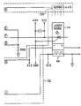
- Figure 4 is a schematic diagram of one implementation of the light source as shown in Figure 3.
- Figure 5 and Figure 6 are graphical representations utilized in the method of calculating scale factor correction from rotation rate and a control signal generated by the light source as shown in Figure 3.
- Figure 7 and Figure 8 are graphical representations utilized in the method of determining scale factor correction from a control signal generated by the light source in accordance with Figure 3.
- Figure 9 is an additional schematic implementation of the light source of Figure 3 in accordance with the present invention.
- Rapid turn-on light source 12 in accordance with the present invention is shown in Figure 1 as the light source for fiber optic gyroscope 10.
- Rapid turn-on light source 12 includes temperature and current control circuitry 16 for driving a laser diode 14 to introduce light into an optical fiber 17.
- Light input to the fiber 17 then propagates to source coupler 18 where the source coupler 18 couples a portion of the light to polarizer 20 while a portion of the light is lost through the non-reflecting ends 19 of the source coupler 18.
- the light propagates from the polarizer to loop coupler 22 where it is split into two counter-propagating waves; the first wave propagating in a clockwise direction around a fiber loop 24 and the second wave propagating in a counterclockwise direction around fiber loop 24.
- Phase modulator 28 provides phase modulation as is known to one skilled in the art. After the waves have traversed the fiber loop 24. they are recombined by coupler 22 to form an optical output signal which propagates from the coupler 22 to source coupler 18 with a portion of the optical output signal lost through non-reflecting ends 23 of the loop coupler 22. A portion of the optical output signal is then coupled from the source coupler 18 for propagation to detector 26. The detector 26 outputs an electrical signal which is proportional to the intensity of the light impressed thereon by the optical output signal.
- the intensity of the optical output signal will vary in accordance with the amount and type of interference between the counterpropagating waves when they are recombined or superimposed at the loop coupler 22.
- the counterpropagating waves will be shifted in phase. in accordance with the Sagnac effect, so that when they are superimposed at the coupler 22 they interfere producing a Sagnac phase difference between the waves caused by rotation of fiber loop 24.
- the intensity of the optical output signal as detected by detector 26 is an effect of the rotation rate of the fiber optic gyroscope; thus. an indication of such rotation rate may be obtained by measuring the intensity of the output signal.
- rotation ⁇ for a closed loop fiber optic gyroscope can be shown in accordance with the following relationship with ⁇ F being the frequency difference representative of phase shift.
- ⁇ [ ⁇ n] D
- the rapid turn-on light source 12 in addition to the analog to digital converter 34 and computer 32, provides a means to compensate for a change in wavelength and improve scale factor performance to achieve such accuracy.
- the rapid turn-on light source 12 maintains substantially a constant source power output intensity within the range of 1 to 2db over a predetermined temperature range. By maintaining such constant power output intensity, the light source 12 is prevented from being damaged by exceeding rating limits of the source circuitry and random noise is kept substantially constant versus temperature.
- the substantially constant power output intensity the light source wavelength spectrum is kept substantially constant which in turn increases bias stability.
- Rapid turn-on light source 12 includes temperature and current control circuitry 16, laser diode 14, and heater 44.
- Temperature and current control circuitry 16 includes voltage control circuitry 40 which generates voltage V 0 for input to source driver 42.
- Source driver 42 forces V 0 to appear at the output of the source driver 42 providing source current IF to drive laser diode 14.
- Voltage control circuitry 40 includes a temperature sensor 120, an AD590 temperature sensor, which is in thermal contact with laser diode 14 to measure the temperature of the laser diode 14 as it heats up due to the heater 44 and/or its self heating power.
- Heater 44 may contribute to temperature stability of the system; however, the heater is not essential as the light source 12 allows the temperature of the diode 14 to float over a predetermined temperature range without performance degradation, as shall be discussed further below.
- a thermo-electric cooler could be used to stabilize temperature.
- the AD590 temperature sensor available from Analog Devices. Inc., Norwood, MA 02062. is close to an ideal current source and a current I 3 is generated upon excitation of the light source 12 almost immediately upon turn-on.
- any current source which approximates the functioning of an AD590 temperature sensor can be used to sense the temperature of the laser diode 14 and produce a signal in accordance therewith.
- the temperature sensor 120 generates a current I 3 which flows through R 3 and is sunk in the low impedance of a buffer operational amplifier 122.
- the current I 3 serves to set the voltage V 0 as a function of temperature since current I 3 varies 1 ⁇ amp/K. In other words, I 3 is approximately 300 ⁇ amps at 300K.
- the variation of temperature sensor current I 3 is such that the voltage V 0 is lower when the device is cooler and higher when the device is hotter.
- the voltage control circuitry 40 further includes a voltage network including V 1 ', R 1 , R 2 and C 1 for generating a voltage V 1 to be selected in accordance with the description provided below.
- the voltage V 0 is applied to the source driver 42 at a non-inverting input of operational amplifier 124.
- the source driver 42 includes a power field effect transistor (FET) 126 having its gate connected to an output of operational amplifier 124 and its drain and source connected to laser diode 14 and ground through resistor R f , respectively.
- FET field effect transistor
- the source driver 42 forces voltage V 0 to appear at the output of the power FET and across resistor R f . Feedback from the source by way of the resistor R4 and capacitor C 2 , enforces such a desired output.
- the source driver 42 drives the laser diode 14 with a source drive current I f equal to V 0 /R f .
- a temperature range having a high and low set point temperature can be selected for the light source wherein scale factor stability and bias stability can be achieved while still allowing fast turn-on with a safe i.e., not overrated, source drive current I f .
- the proper source coherence function can also be achieved over this temperature range as well.
- the rapid turn-on light source 12 of the present invention has source drive current If equal to V o /R 3 at turn-on because the AD590 temperature sensor 120 is extremely fast and temperature sensor current I 3 is sunk in buffer 122 before the voltage V 1 has reached -.54 volts. As such, damaging currents can be avoided by appropriate selection of the selected impedances and voltages to keep the source drive current I f from exceeding the maximum rated I f for the laser diode 14. In accordance with the light source 12 implementation of Figure 4.
- I f max is equal to 150 mA. the maximum source drive current I f for the laser diode 14 is not exceeded and when V 1 has reached -.54 volts a stable rapidly turned-on source is achieved.
- the voltage V 0 generated by voltage control circuit 40 utilizing temperature sensor 120 is representative of the light source's temperature T S and a source drive current If.
- the change in scale factor due to the changing wavelength of the light source was dependent upon change in temperature of the source ⁇ T S and change in source drive current ⁇ I f . along with other parameters of less importance.
- V 0 is representative of the source's temperature T s and drive current If, a change in V 0 also indicates a change in scale factor. Therefore. the voltage V 0 utilized for driving the laser diode 14 via source drive current I f can also be utilized to correct for scale factor changes as shall be described in further detail below.
- V 0 is applied to an analog to digital converter 34.
- the voltage V 0 is digitized and the digitized V 0 is applied to computer 32 to be processed for scale factor correction.
- Computer 32 includes a processor and memory for generating the appropriate scale factor to apply to the frequency difference of the counterpropagating waves detected by detector 26 and processed by electronics 30.
- the electronics 30 may include a demodulator. amplifiers and other necessary electronics; such electronics are known to one skilled in the art.
- Computer 32 applies a scale factor to the frequency difference or phase shift to determine a corrected rotation rate output 36 or angle output ⁇ being the integral of the rate output over time.
- the fiber optic gyroscope is characterized at various fiber optic gyroscope soak temperatures.
- the source temperature will float in correspondence with the soak temperatures.
- the voltage V 0 being representative of the source temperature T s and the source drive current I f at various soak temperatures T l , T K , T n ,the scale factors for various rotation rates result as shown in Figure 5.
- such scale factor equations produce a complicated 3-D surface 46 which can be used to recover the scale factor given the rotation rate which is obtainable from navigation and computer calculation and the measured V 0 from the light source.
- V 0 which is representative of temperature and drive current can be used directly with a known rotation rate from navigation and computer calculation to select an accurate scales factor. This method assures both good scale factor linearity and good scale factor repeatability.
- the fiber optic gyroscope is characterized at various fiber optic gyroscope soak temperatures as shown in Figure 7; those temperatures being T 1 , T K , T n .
- an average scale factor as shown in Figure 7 is computed.
- Neither of the scale factors is rate dependent because the average scale factor is computed.
- the temperature dependence of V 0 is applied and a least squares curve fit 48 for the curve 50 is determined.
- more than a first order equation may be used, for simplicity. only the A and B terms of the above equation are utilized and the scale factor versus V 0 which is dependent on temperature and drive current can be shown by line 48.
- the data arrived at is discrete but is shown in Figure 8 as continuous.
- the second method gives good scale factor repeatability, but scale factor linearity depends on variations ignored in the scale factor versus rotation rate curve.
- the memory of computer 32 may include an algorithm in accordance with the equations above for determining scale factor from V 0 upon application of the digitized voltage V 0 by analog to digital converter 34 to computer 32.
- a proper scale factor is computed utilizing computer 32 and applied to the detected output.
- the corrected scale factor rotation rate output 36 is generated.
- the scale factors for various values of V 0 could be calculated and a look-up table utilized, which implies that an algorithm can also be utilized, for selecting the proper scale factor in accordance with V 0 .
- Figure 9 shows another implementation of the light source 12 of the present invention.
- Light source 12 may be mounted with several other sources 62. 64 on one block.
- Source 62 includes source driver 66 and heater driver 68.
- Source driver 66 drives laser diode 70 and heater driver 68 drives heater 72.
- Source 64 would include source driver 74 which drives laser diode 78 and heater driver 76 for driving heater 80.
- the drivers of both sources 62. 64 have voltage V 0 as the input for the source drivers 66, 74 and a second reference voltage V R for input to the heater driver 68 and 76.
- Each of the sources 62 and 64 is an equivalent of the source driver 42, heater driver 52, laser diode 14 and heater 44 of light source 12.
- the voltage control circuitry 40 which includes the temperature sensor 120 provides the voltage V 0 to each of the source drivers 42, 66 and 74 and reference voltage V R to each of the heater drivers 52. 68, and 76.
- the heater could be a thermal foil heater and that only one heater could be used for the entire block rather than three separate heaters. 44. 72 and 80.
- a thermo-electric cooler can also be utilized to stabilize the temperature of the laser diode. Both the heaters and/or cooler utilize feedback for control thereof.
- Light source 12 shows a more detailed schematic of the light source of in Figure 4.
- the voltage drive circuitry 40 includes temperature sensor 120 having a supply voltage of 5 volts applied thereto for generating a current in accordance with the temperature of laser diode 14 to be sunk through resistor R3, a 6.8k ohms resistor. into buffer 122.
- a voltage regulator 130 in conjunction with the 10K resistor R26. the .1 ⁇ f capacitor across the 10K resistor, the -12 volt supply, the 3.32K resistor R27, the 82K resistor R29. and the .006 ⁇ f capacitor C20 across the voltage regulator produces a voltage V 1 of -.54 volts for input to buffer 122.
- An appropriate voltage is input to operational amplifier 132 for generating a voltage V R for input to the heater drive circuit 52.
- Voltage V 0 is applied to operational amplifier 124 which forces V 0 to appear at the output of power FET 126.
- the power FET is an IRFR9020 with a diode thereacross for overload protection.
- Feedback of V 0 to the inverting input of operational amplifier 124 is provided via the 15K resistor and 8200pf capacitor.
- the 8200pf capacitor could also be positioned across the 15K resistor.
- Resistors R40 and R50 are selected to produce a 25 ohm resistance for producing a source drive current I f for laser diode 14 equal to V 0 /25 ohms.
- the temperature sensor 120 is thermally coupled to the laser diodes 14. 70, 78.
- the heater driver 52 is similar to the source driver 42 and is shown in Figure 9. Further discussion thereof is limited as driver circuits are readily known to one skilled in the art.
Description
Claims (14)
- A light source apparatus for a fiber optic rotation sensor (10), said apparatus comprising:characterized bya light source (14) to provide light for input to the fiber optic rotation sensor (10);source control means (16) for generating a source control signal representative of a temperature of said light source (14); andmeans (32) for generating one of a plurality of scale factors for the fiber optic rotation sensor (10) as a function of said light source control signal over a predetermined temperature range; and
drive means (16) for generating a drive signal as a function of said source control signal to drive said light source (14). - Apparatus according to Claim 1, wherein said source control means (16) includes:a temperature sensor (120) providing a current signal representative of said temperature of said light source (14); anda buffer network (122) for sinking said current signal and for generating a source control voltage as said source control signal.
- Apparatus according to Claim 2, wherein said buffer network (122) includes a buffer having an output with a first selected impedance connected between said output and an input of said drive means (16) and a non-inverting input having a selected voltage applied thereto, said source control voltage substantially equal to a voltage across said first selected impedance as said current signal is sunk in said buffer and said selected voltage.
- Apparatus according to Claim 3, wherein said drive means (16) includes said input for receiving said source control voltage; and means (42) for forcing and providing said source control voltage at an output of said drive means (16) and across a second selected impedance connected to ground to generate a drive current as said drive signal for driving said light source (14), said first and second selected impedances and said selected voltage being determined as a function of predetermined first and second set point temperatures defining said predetermined temperature range and predetermined drive currents for said set point temperatures.
- Apparatus according to Claim 4, wherein said forcing means (42) includes:an op amp (124) having an inverting input, a non-inverting input and an output, said non-inverting input being said input of said forcing means (42) for receiving said source control voltage; anda transistor (126) connected to said output of said op amp (124), said light source (14) and said second selected impedance to provide said source control voltage at an output thereof and across said second selected impedance, to provide said drive current therethrough for driving said light source (14), and to provide feedback to said inverting input of said op amp (124).
- Apparatus according to Claim 1, wherein said generation means includes:an analog to digital converter (34) for converting said source control signal to a digitized signal; andcomputer means (32) for receiving said digitized signal and generating one of a plurality of scale factors based on a plurality of temperatures of said light source (14) for a plurality of rotation rates of the fiber optic rotation sensor (10) as a function of said digitized signal representative of said source control signal.
- Apparatus according to Claim 1, further comprising a heat source (44) for heating or a thermo-electric cooler for cooling said light source (14) to stabilize said light source to a particular temperature.
- Apparatus according to Claim 1, wherein said light source (14) is a laser diode.
- Apparatus according to any one of the preceding claims, wherein
said drive means (16) serve to generate a drive signal as a function of said source control signal to drive said light source (14), wherein said light source (14) is substantially immediately turned on by said drive signal upon excitation of said apparatus, said source control means (16) preventing said drive signal from exceeding a predetermined safe maximum current whether said light source (14) is at a low temperature or high temperature of a predetermined temperature range. - A method of light source wavelength compensation for a fiber optic rotation sensor (10), comprising the steps of:providing a light source (14);sensing a temperature of said light source (14) and generating a source control signal representative thereof;applying a drive signal to said light source (14) as a function of said source control signal; andgenerating a scale factor for said fiber optic rotation sensor (10) as a function of said source control signal.
- Method according to Claim 10, wherein said temperature sensing and source control signal generating step includes the steps of:generating a current signal representative of the temperature of said light source (14);sinking said current signal into a buffer network (122) through a first selected impedance; andgenerating a source control voltage as said source control signal as a function of said voltage across said first selected impedance and a selected voltage of said buffer network (122).
- Method according to Claim 11, wherein said drive signal applying step includes the step of driving said light source (14) with a drive signal generated by application of said source control voltage across a second selected impedance.
- Method according to Claim 12, wherein said first selected impedance, said second selected impedance, and said selected voltage are chosen for a temperature range having a lower and upper set point allowing for fast turn-on of said light source (14) with a drive signal that does not exceed a predetermined maximum drive signal for said light source of either said lower or upper set point.
- Method according to Claim 10, wherein said scale factor generation step includes the steps of:converting said source control signal to a digitized signal; andgenerating one of a plurality of scale factors based on a plurality of temperatures of said light source (14) for a plurality of rotation rates of the fiber optic rotation sensor (10) as a function of said digitized signal.
Applications Claiming Priority (3)
| Application Number | Priority Date | Filing Date | Title |
|---|---|---|---|
| US08/055,133 US5410515A (en) | 1993-04-29 | 1993-04-29 | Rapid turn-on source for fiber optic gyroscope |
| US55133 | 1993-04-29 | ||
| PCT/US1994/004790 WO1994025826A1 (en) | 1993-04-29 | 1994-04-29 | Rapid turn-on source for fiber optic gyroscope |
Publications (3)
| Publication Number | Publication Date |
|---|---|
| EP0696348A1 EP0696348A1 (en) | 1996-02-14 |
| EP0696348B1 true EP0696348B1 (en) | 1998-03-18 |
| EP0696348B2 EP0696348B2 (en) | 2005-08-03 |
Family
ID=21995843
Family Applications (1)
| Application Number | Title | Priority Date | Filing Date |
|---|---|---|---|
| EP94916625A Expired - Lifetime EP0696348B2 (en) | 1993-04-29 | 1994-04-29 | Rapid turn-on source for fiber optic gyroscope |
Country Status (6)
| Country | Link |
|---|---|
| US (1) | US5410515A (en) |
| EP (1) | EP0696348B2 (en) |
| JP (1) | JPH08510323A (en) |
| CA (1) | CA2157679C (en) |
| DE (1) | DE69409103T3 (en) |
| WO (1) | WO1994025826A1 (en) |
Families Citing this family (11)
| Publication number | Priority date | Publication date | Assignee | Title |
|---|---|---|---|---|
| JP2871623B2 (en) * | 1996-07-11 | 1999-03-17 | 日本電気株式会社 | Semiconductor laser device |
| US6359918B1 (en) | 1998-06-30 | 2002-03-19 | Honeywell International Inc. | Light source control device |
| US6108358A (en) * | 1998-10-13 | 2000-08-22 | Honeywell Inc. | Apparatus for minimizing the effects of laser intensity reduction at cold temperatures in ring laser gyros |
| US6696887B2 (en) * | 2001-09-27 | 2004-02-24 | Matthew S. Taubman | Transistor-based interface circuitry |
| US6587490B2 (en) * | 2001-10-02 | 2003-07-01 | Analog Modules, Inc | Low-noise current source driver for laser diodes |
| US8213018B2 (en) | 2010-11-10 | 2012-07-03 | Honeywell International Inc. | Constant optical power sensor using a light source current servo combined with digital demodulation intensity suppression for radiation and vibration insensitivity in a fiber optic gyroscope |
| CN104990547B (en) * | 2015-08-13 | 2017-10-20 | 北京航空航天大学 | The method and apparatus that a kind of stable fiber gyro keeps constant multiplier |
| WO2018063232A1 (en) * | 2016-09-29 | 2018-04-05 | Halliburton Energy Services, Inc. | Distributed temperature sensing over extended temperature ranges |
| US11396794B2 (en) | 2018-05-29 | 2022-07-26 | Baker Hughes, A Ge Company, Llc | Device temperature gradient control |
| WO2021076462A1 (en) * | 2019-10-16 | 2021-04-22 | Panasonic intellectual property Management co., Ltd | Cold-start acceleration for wavelength-beam-combining laser resonators |
| CN113124899B (en) * | 2021-03-23 | 2022-09-16 | 西安航天精密机电研究所 | Method for acquiring variable-temperature scale factor of fiber optic gyroscope based on simulation technology |
Family Cites Families (9)
| Publication number | Priority date | Publication date | Assignee | Title |
|---|---|---|---|---|
| GB2157425B (en) * | 1984-03-29 | 1987-08-12 | British Aerospace | Fibre interferometric sensors |
| JPH0392734A (en) † | 1989-09-04 | 1991-04-17 | Sumitomo Electric Ind Ltd | Measuring method for environment temperature by use of optical fiber sensor |
| US5018154A (en) * | 1989-09-12 | 1991-05-21 | Brother Kogyo Kabushiki Kaisha | Semiconductor laser drive device |
| US5043992A (en) * | 1989-10-06 | 1991-08-27 | At&T Bell Laboratories | Laser driver with temperature compensation |
| US5024535A (en) † | 1989-12-20 | 1991-06-18 | United Technologies Corporation | Semiconductor light source temperature measurement |
| JP2632236B2 (en) * | 1990-09-27 | 1997-07-23 | 日本航空電子工業 株式会社 | Optical interference angular velocity meter |
| DE4037118C1 (en) † | 1990-11-22 | 1992-04-30 | Messerschmitt-Boelkow-Blohm Gmbh, 8012 Ottobrunn, De | |
| JP2697357B2 (en) * | 1991-05-14 | 1998-01-14 | 日立電線株式会社 | Optical fiber rotation angular velocity sensor |
| JP2818329B2 (en) * | 1991-11-29 | 1998-10-30 | 日立電線株式会社 | Fiber optic gyro |
-
1993
- 1993-04-29 US US08/055,133 patent/US5410515A/en not_active Expired - Lifetime
-
1994
- 1994-04-29 DE DE69409103T patent/DE69409103T3/en not_active Expired - Lifetime
- 1994-04-29 JP JP6524594A patent/JPH08510323A/en active Pending
- 1994-04-29 EP EP94916625A patent/EP0696348B2/en not_active Expired - Lifetime
- 1994-04-29 CA CA002157679A patent/CA2157679C/en not_active Expired - Fee Related
- 1994-04-29 WO PCT/US1994/004790 patent/WO1994025826A1/en active IP Right Grant
Also Published As
| Publication number | Publication date |
|---|---|
| JPH08510323A (en) | 1996-10-29 |
| CA2157679A1 (en) | 1994-11-10 |
| DE69409103D1 (en) | 1998-04-23 |
| EP0696348B2 (en) | 2005-08-03 |
| CA2157679C (en) | 2001-04-10 |
| DE69409103T2 (en) | 1998-09-24 |
| US5410515A (en) | 1995-04-25 |
| WO1994025826A1 (en) | 1994-11-10 |
| EP0696348A1 (en) | 1996-02-14 |
| DE69409103T3 (en) | 2006-05-18 |
Similar Documents
| Publication | Publication Date | Title |
|---|---|---|
| EP0696348B1 (en) | Rapid turn-on source for fiber optic gyroscope | |
| EP1171754B1 (en) | Kerr effect compensation for an interferometric fiber optic gyroscope | |
| US7515271B2 (en) | Wavelength calibration in a fiber optic gyroscope | |
| CA2040484C (en) | Fiber optic measuring device, rate gyro, navigation and stabilization system, and current sensor | |
| EP1499856B1 (en) | Apparatus for dead band error suppression in fiber optic gyroscopes | |
| JP2008216256A (en) | Methods and systems for optical fiber gyroscopes vibration error suppression | |
| EP1718929B1 (en) | System and method for reducing fiber optic gyroscope color noise | |
| JP2007147628A (en) | Method and system for calibrating optical fiber gyroscope | |
| US6181428B1 (en) | Closed loop fiber optic gyro with shupe effect compensation | |
| US5020913A (en) | Fiber optic gyro with temperature compensated phase ramp | |
| EP3786582B1 (en) | Systems and methods for correcting errors in gyroscopes | |
| CN105547279B (en) | Gyro rate calculation for interferometric fiber optic gyroscope | |
| US7038786B2 (en) | Optical interferometric sensor with measureand compensation that may selectively be used for temperature compensation and long term life degradation | |
| Celikel | Application of the vector modulation method to the north finder capability gyroscope as a directional sensor | |
| US5337143A (en) | Loop controller for multiplexed triaxial gyro | |
| Çelikel | Construction and characterization of interferometric fiber optic gyroscope (IFOG) with erbium doped fiber amplifier (EDFA) | |
| US5202747A (en) | Fiber optic gyroscope with wide dynamic range analog phase tracker | |
| Bielas et al. | Test results of a prototype serrodyne closed-loop interferometric fiber optic gyroscope | |
| JPH10132577A (en) | Optical fiber gyroscope | |
| WO2001029511A1 (en) | An open loop fiber optic gyroscope for measuring ultra-high rates of rotation | |
| JP2557658B2 (en) | Optical interference gyro | |
| JP2004093321A (en) | Bridge circuit type detector | |
| JP2632236B2 (en) | Optical interference angular velocity meter | |
| Celikel et al. | Construction of all digital closed-loop interferometric fiber optic gyroscope with erbium doped fiber amplifier | |
| Lu et al. | Effects of phase modulator characteristics on interferometer system performance |
Legal Events
| Date | Code | Title | Description |
|---|---|---|---|
| PUAI | Public reference made under article 153(3) epc to a published international application that has entered the european phase |
Free format text: ORIGINAL CODE: 0009012 |
|
| 17P | Request for examination filed |
Effective date: 19951020 |
|
| AK | Designated contracting states |
Kind code of ref document: A1 Designated state(s): DE FR GB IT NL |
|
| GRAG | Despatch of communication of intention to grant |
Free format text: ORIGINAL CODE: EPIDOS AGRA |
|
| GRAG | Despatch of communication of intention to grant |
Free format text: ORIGINAL CODE: EPIDOS AGRA |
|
| GRAH | Despatch of communication of intention to grant a patent |
Free format text: ORIGINAL CODE: EPIDOS IGRA |
|
| 17Q | First examination report despatched |
Effective date: 19970901 |
|
| GRAH | Despatch of communication of intention to grant a patent |
Free format text: ORIGINAL CODE: EPIDOS IGRA |
|
| GRAA | (expected) grant |
Free format text: ORIGINAL CODE: 0009210 |
|
| AK | Designated contracting states |
Kind code of ref document: B1 Designated state(s): DE FR GB IT NL |
|
| REF | Corresponds to: |
Ref document number: 69409103 Country of ref document: DE Date of ref document: 19980423 |
|
| ET | Fr: translation filed | ||
| ITF | It: translation for a ep patent filed |
Owner name: BARZANO' E ZANARDO ROMA S.P.A. |
|
| PLBQ | Unpublished change to opponent data |
Free format text: ORIGINAL CODE: EPIDOS OPPO |
|
| PLBI | Opposition filed |
Free format text: ORIGINAL CODE: 0009260 |
|
| PLBF | Reply of patent proprietor to notice(s) of opposition |
Free format text: ORIGINAL CODE: EPIDOS OBSO |
|
| 26 | Opposition filed |
Opponent name: LITEF GMBH Effective date: 19981217 |
|
| NLR1 | Nl: opposition has been filed with the epo |
Opponent name: LITEF GMBH |
|
| PLBF | Reply of patent proprietor to notice(s) of opposition |
Free format text: ORIGINAL CODE: EPIDOS OBSO |
|
| PLAW | Interlocutory decision in opposition |
Free format text: ORIGINAL CODE: EPIDOS IDOP |
|
| APAC | Appeal dossier modified |
Free format text: ORIGINAL CODE: EPIDOS NOAPO |
|
| APAE | Appeal reference modified |
Free format text: ORIGINAL CODE: EPIDOS REFNO |
|
| APAC | Appeal dossier modified |
Free format text: ORIGINAL CODE: EPIDOS NOAPO |
|
| REG | Reference to a national code |
Ref country code: GB Ref legal event code: IF02 |
|
| APBU | Appeal procedure closed |
Free format text: ORIGINAL CODE: EPIDOSNNOA9O |
|
| PGFP | Annual fee paid to national office [announced via postgrant information from national office to epo] |
Ref country code: NL Payment date: 20050316 Year of fee payment: 12 |
|
| PUAH | Patent maintained in amended form |
Free format text: ORIGINAL CODE: 0009272 |
|
| STAA | Information on the status of an ep patent application or granted ep patent |
Free format text: STATUS: PATENT MAINTAINED AS AMENDED |
|
| 27A | Patent maintained in amended form |
Effective date: 20050803 |
|
| AK | Designated contracting states |
Kind code of ref document: B2 Designated state(s): DE FR GB IT NL |
|
| NLR2 | Nl: decision of opposition |
Effective date: 20050803 |
|
| APAH | Appeal reference modified |
Free format text: ORIGINAL CODE: EPIDOSCREFNO |
|
| NLR3 | Nl: receipt of modified translations in the netherlands language after an opposition procedure | ||
| ET3 | Fr: translation filed ** decision concerning opposition | ||
| PG25 | Lapsed in a contracting state [announced via postgrant information from national office to epo] |
Ref country code: NL Free format text: LAPSE BECAUSE OF NON-PAYMENT OF DUE FEES Effective date: 20061101 |
|
| NLV4 | Nl: lapsed or anulled due to non-payment of the annual fee |
Effective date: 20061101 |
|
| PGFP | Annual fee paid to national office [announced via postgrant information from national office to epo] |
Ref country code: GB Payment date: 20080317 Year of fee payment: 15 |
|
| PGFP | Annual fee paid to national office [announced via postgrant information from national office to epo] |
Ref country code: IT Payment date: 20080419 Year of fee payment: 15 |
|
| GBPC | Gb: european patent ceased through non-payment of renewal fee |
Effective date: 20090429 |
|
| PG25 | Lapsed in a contracting state [announced via postgrant information from national office to epo] |
Ref country code: GB Free format text: LAPSE BECAUSE OF NON-PAYMENT OF DUE FEES Effective date: 20090429 |
|
| PG25 | Lapsed in a contracting state [announced via postgrant information from national office to epo] |
Ref country code: IT Free format text: LAPSE BECAUSE OF NON-PAYMENT OF DUE FEES Effective date: 20090429 |
|
| PGFP | Annual fee paid to national office [announced via postgrant information from national office to epo] |
Ref country code: DE Payment date: 20130430 Year of fee payment: 20 |
|
| PGFP | Annual fee paid to national office [announced via postgrant information from national office to epo] |
Ref country code: FR Payment date: 20130417 Year of fee payment: 20 |
|
| REG | Reference to a national code |
Ref country code: DE Ref legal event code: R071 Ref document number: 69409103 Country of ref document: DE |
|
| PG25 | Lapsed in a contracting state [announced via postgrant information from national office to epo] |
Ref country code: DE Free format text: LAPSE BECAUSE OF EXPIRATION OF PROTECTION Effective date: 20140430 |