EP0696109A2 - Method of selecting input apparatus - Google Patents
Method of selecting input apparatus Download PDFInfo
- Publication number
- EP0696109A2 EP0696109A2 EP95305343A EP95305343A EP0696109A2 EP 0696109 A2 EP0696109 A2 EP 0696109A2 EP 95305343 A EP95305343 A EP 95305343A EP 95305343 A EP95305343 A EP 95305343A EP 0696109 A2 EP0696109 A2 EP 0696109A2
- Authority
- EP
- European Patent Office
- Prior art keywords
- apparatuses
- vtr
- input
- electronic apparatuses
- output
- Prior art date
- Legal status (The legal status is an assumption and is not a legal conclusion. Google has not performed a legal analysis and makes no representation as to the accuracy of the status listed.)
- Withdrawn
Links
- 238000000034 method Methods 0.000 title claims description 35
- 238000004891 communication Methods 0.000 claims abstract description 88
- 230000005540 biological transmission Effects 0.000 description 14
- 230000004044 response Effects 0.000 description 8
- ZHBXLZQQVCDGPA-UHFFFAOYSA-N 5-[(1,3-dioxo-2-benzofuran-5-yl)sulfonyl]-2-benzofuran-1,3-dione Chemical compound C1=C2C(=O)OC(=O)C2=CC(S(=O)(=O)C=2C=C3C(=O)OC(C3=CC=2)=O)=C1 ZHBXLZQQVCDGPA-UHFFFAOYSA-N 0.000 description 2
- 230000009471 action Effects 0.000 description 2
- 238000010586 diagram Methods 0.000 description 2
- 230000006870 function Effects 0.000 description 2
- 239000000203 mixture Substances 0.000 description 2
- 230000004048 modification Effects 0.000 description 2
- 238000012986 modification Methods 0.000 description 2
- 238000012544 monitoring process Methods 0.000 description 2
- 230000001174 ascending effect Effects 0.000 description 1
- 230000008859 change Effects 0.000 description 1
- 238000007796 conventional method Methods 0.000 description 1
- 230000008569 process Effects 0.000 description 1
- 238000001454 recorded image Methods 0.000 description 1
- 230000000630 rising effect Effects 0.000 description 1
- 238000010187 selection method Methods 0.000 description 1
Images


Classifications
-
- G—PHYSICS
- G11—INFORMATION STORAGE
- G11B—INFORMATION STORAGE BASED ON RELATIVE MOVEMENT BETWEEN RECORD CARRIER AND TRANSDUCER
- G11B25/00—Apparatus characterised by the shape of record carrier employed but not specific to the method of recording or reproducing, e.g. dictating apparatus; Combinations of such apparatus
- G11B25/02—Apparatus characterised by the shape of record carrier employed but not specific to the method of recording or reproducing, e.g. dictating apparatus; Combinations of such apparatus using cylindrical record carriers
-
- H—ELECTRICITY
- H04—ELECTRIC COMMUNICATION TECHNIQUE
- H04L—TRANSMISSION OF DIGITAL INFORMATION, e.g. TELEGRAPHIC COMMUNICATION
- H04L12/00—Data switching networks
- H04L12/28—Data switching networks characterised by path configuration, e.g. LAN [Local Area Networks] or WAN [Wide Area Networks]
- H04L12/2803—Home automation networks
-
- G—PHYSICS
- G11—INFORMATION STORAGE
- G11B—INFORMATION STORAGE BASED ON RELATIVE MOVEMENT BETWEEN RECORD CARRIER AND TRANSDUCER
- G11B27/00—Editing; Indexing; Addressing; Timing or synchronising; Monitoring; Measuring tape travel
- G11B27/02—Editing, e.g. varying the order of information signals recorded on, or reproduced from, record carriers
- G11B27/031—Electronic editing of digitised analogue information signals, e.g. audio or video signals
-
- G—PHYSICS
- G11—INFORMATION STORAGE
- G11B—INFORMATION STORAGE BASED ON RELATIVE MOVEMENT BETWEEN RECORD CARRIER AND TRANSDUCER
- G11B27/00—Editing; Indexing; Addressing; Timing or synchronising; Monitoring; Measuring tape travel
- G11B27/36—Monitoring, i.e. supervising the progress of recording or reproducing
-
- G—PHYSICS
- G11—INFORMATION STORAGE
- G11B—INFORMATION STORAGE BASED ON RELATIVE MOVEMENT BETWEEN RECORD CARRIER AND TRANSDUCER
- G11B31/00—Arrangements for the associated working of recording or reproducing apparatus with related apparatus
-
- H—ELECTRICITY
- H04—ELECTRIC COMMUNICATION TECHNIQUE
- H04B—TRANSMISSION
- H04B1/00—Details of transmission systems, not covered by a single one of groups H04B3/00 - H04B13/00; Details of transmission systems not characterised by the medium used for transmission
- H04B1/06—Receivers
- H04B1/16—Circuits
- H04B1/20—Circuits for coupling gramophone pick-up, recorder output, or microphone to receiver
- H04B1/202—Circuits for coupling gramophone pick-up, recorder output, or microphone to receiver by remote control
-
- H—ELECTRICITY
- H04—ELECTRIC COMMUNICATION TECHNIQUE
- H04L—TRANSMISSION OF DIGITAL INFORMATION, e.g. TELEGRAPHIC COMMUNICATION
- H04L12/00—Data switching networks
- H04L12/28—Data switching networks characterised by path configuration, e.g. LAN [Local Area Networks] or WAN [Wide Area Networks]
- H04L12/2803—Home automation networks
- H04L12/2816—Controlling appliance services of a home automation network by calling their functionalities
- H04L12/282—Controlling appliance services of a home automation network by calling their functionalities based on user interaction within the home
-
- H—ELECTRICITY
- H04—ELECTRIC COMMUNICATION TECHNIQUE
- H04L—TRANSMISSION OF DIGITAL INFORMATION, e.g. TELEGRAPHIC COMMUNICATION
- H04L12/00—Data switching networks
- H04L12/28—Data switching networks characterised by path configuration, e.g. LAN [Local Area Networks] or WAN [Wide Area Networks]
- H04L12/40—Bus networks
- H04L12/40052—High-speed IEEE 1394 serial bus
- H04L12/40117—Interconnection of audio or video/imaging devices
-
- H—ELECTRICITY
- H04—ELECTRIC COMMUNICATION TECHNIQUE
- H04N—PICTORIAL COMMUNICATION, e.g. TELEVISION
- H04N5/00—Details of television systems
- H04N5/222—Studio circuitry; Studio devices; Studio equipment
- H04N5/262—Studio circuits, e.g. for mixing, switching-over, change of character of image, other special effects ; Cameras specially adapted for the electronic generation of special effects
- H04N5/268—Signal distribution or switching
-
- H—ELECTRICITY
- H04—ELECTRIC COMMUNICATION TECHNIQUE
- H04N—PICTORIAL COMMUNICATION, e.g. TELEVISION
- H04N5/00—Details of television systems
- H04N5/76—Television signal recording
- H04N5/765—Interface circuits between an apparatus for recording and another apparatus
- H04N5/77—Interface circuits between an apparatus for recording and another apparatus between a recording apparatus and a television camera
-
- H—ELECTRICITY
- H04—ELECTRIC COMMUNICATION TECHNIQUE
- H04L—TRANSMISSION OF DIGITAL INFORMATION, e.g. TELEGRAPHIC COMMUNICATION
- H04L12/00—Data switching networks
- H04L12/28—Data switching networks characterised by path configuration, e.g. LAN [Local Area Networks] or WAN [Wide Area Networks]
- H04L12/2803—Home automation networks
- H04L2012/2847—Home automation networks characterised by the type of home appliance used
- H04L2012/2849—Audio/video appliances
-
- H—ELECTRICITY
- H04—ELECTRIC COMMUNICATION TECHNIQUE
- H04N—PICTORIAL COMMUNICATION, e.g. TELEVISION
- H04N5/00—Details of television systems
- H04N5/44—Receiver circuitry for the reception of television signals according to analogue transmission standards
- H04N5/445—Receiver circuitry for the reception of television signals according to analogue transmission standards for displaying additional information
Definitions
- the present invention relates to a method of selecting an electronic apparatus in such a system to serve as a source of data when data is to be input to each of the electronic apparatuses from the desired electronic apparatus.
- VTR video tape recorder
- TV television set
- CAM camera
- This communication system includes VTR's 1, 2, and 3 and a CAM 1. Connection between the CAM 1 and VTR 1, VTR 1 and VTR 2, and VTR 2 and VTR 3 is established by P1394 serial buses. Since each of those electronic apparatuses has a function of repeating control signals and data on a P1394 serial bus, this system is equivalent to a communication system in which electronic apparatuses are connected to a common P1394 serial bus.
- Fig. 14 is a block diagram showing a basic configuration of a VTR as an example of the electronic apparatuses in the communication system shown in Fig. 13.
- This VTR includes a deck portion 1, a tuner portion 2, an operation portion 3 and a display portion 4 serving as a user interface, a microcomputer 5 which performs the creation of packets to be described later, the storage of addresses and data, and the like, a digital interface 6 for interface with a P1394 serial bus, and a switch box portion 7 for switching signals between the deck portion 1, tuner portion 2, and digital interface 6.
- this electronic apparatus is a television set, a monitor portion and an amplifier portion are provided instead of the deck portion 1 and the display portion 14 is not included.
- the apparatus is a CAM, a camera portion is provided instead of the tuner portion 2.
- communication is performed in predetermined communication cycles (e.g., 125 c. each) as shown in Fig. 15. It is possible to perform both of isochronous communication wherein data such as digital AV signals is continuously transmitted at a predetermined data rate and asynchronous communication wherein control signals such as connection control commands are irregularly transmitted as needed.
- predetermined communication cycles e.g., 125 c. each
- control signals such as connection control commands are irregularly transmitted as needed.
- a cycle start packet CSP is provided at the beginning of a communication cycle and is followed by a period which is set for transmission of isochronous communication packets.
- the communication packets are assigned channel Nos. 1, 2, 3, ..., N to allow simultaneous communication of a plurality of channels. For example, if communication from the CAM 1 to VTR 1 is assigned the channel No. 1, the CAM 1 transmits isochronous communication packets having the channel No. 1 immediately after the cycle start packet CSP, and the VTR 1 monitors the bus and accepts the isochronous communication packets having the channel No. 1 to establish the communication.
- the communication from the VTR 2 to VTR 3 can take place concurrently with the communication from the CAM 1 to the VTR 1. Then, asynchronous communication is carried out using a period that starts when the transmission of the isochronous communication packets is completed for all the channels to be transmitted and lasts until the next cycle start packet CSP.
- each electronic apparatus connected by the bus is automatically assigned a node ID (physical address) depending on the mode of connection.
- node ID physical address
- the bus is reset and node ID's are automatically reassigned depending on the new mode of connection.
- each electronic apparatus since each electronic apparatus is compatible with a D2B (domestic digital bus), it has a logical address (D2B address) which depends on the category it belongs to (CAM 1, VTR 1, VTR 2, or VTR 4) in addition to the physical address as described above.
- D2B addresses are characterized in that they are determined in the order in which apparatuses are initially connected to a communication system and are kept unchanged even after a bus reset for apparatuses which have not been removed from the system.
- VTR 1 and VTR 2 which are the D2B addresses of the source and destination, respectively, are kept unchanged, and the dubbing between the VTR's 1 and 2 can be continued.
- the apparatus issues an inquiry to all other electronic apparatuses in the system using an asynchronous communication packet to know whether they are D2B-compatible and displays on the display portion 4 the D2B addresses of the electronic apparatuses other than itself which have been identified as D2B-compatible apparatuses.
- VTR 3 in Fig. 13 will display as shown in Fig. 16.
- VTR 3 is the logical address of the VTR 3 itself according to its category.
- the window "input apparatus” shows the categorized logical addresses of the apparatuses which are candidates for the selection of an input apparatus.
- the display shows VTR 1, VTR 2, and CAM 1.
- operation keys for moving the cursor and an execution key are displayed on the right of the window showing the input apparatuses.
- the user selects an input apparatus by moving the cursor to the position of the desired apparatus and by designating the execution key while monitoring the contents of the display.
- the channels shown in Fig. 16 are the channels of the television broadcasts selected by the VTR's and the tuner of the television.
- This communication system includes a TV 1, VTR's 1, 2, 3, and a CAM 1.
- the connection between the TV 1 and VTR 1, VTR 1 and VTR 2, VTR 2 and VTR 3, and VTR 3 and CAM 1 is established by P1394 serial buses capable of transmitting a mixture of control signals and data. Since each of the electronic apparatuses has a function of relaying the control signals and data on the P1394 serial bus, this system is equivalent to a communication system wherein a electronic apparatuses are connected to a common P1394 serial bus.
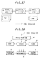
- Fig. 28 is a block diagram showing a basic configuration of a VTR as an example of the electronic apparatuses in the communication system shown in Fig. 27.
- This VTR includes a deck portion 11, a tuner portion 12, an operation portion 13 and a display portion 14 serving as a user interface, a microcomputer 15 which performs the creation of packets to be described later, the storage of addresses and data, and the like, a digital interface 16 for interface with a P1394 serial bus, and a switch box portion 17 for switching signals between the deck portion 11, tuner portion 12, and digital interface 16.
- this electronic apparatus is a television set, a monitor portion and an amplifier portion are provided instead of the deck portion 11 and the display portion 14 is not included.
- the apparatus is a CAM, a camera portion is provided instead of the tuner portion 12.
- communication is performed in predetermined communication cycles (eg 125 ⁇ sec. each) as shown in Fig. 15. It is possible to perform both of isochronous communication wherein data such as digital AV signals is continuously transmitted at a predetermined data rate and asynchronous communication wherein control signals such as connection control commands are irregularly transmitted as needed.
- a cycle start packet CSP is provided at the beginning of a communication cycle and is followed by a period which is set for transmission of isochronous communication packets.
- the communication packets are assigned channel Nos. 1, 2, 3, ..., N to allow simultaneous communication of a plurality of channels. For example, if communication from the CAM 1 to VTR 1 is assigned the channel No. 1, the CAM 1 transmits isochronous communication packets having the channel No. 1 immediately after the cycle start packet CSP, and the VTR 1 monitors the bus and accepts the isochronous communication packets having the channel No. 1 to establish the communication.
- the communication from the VTR 2 to VTR 3 can take place concurrently with the communication from the CAM 1 to VTR 1.
- the asynchronous communication is carried out using a period that starts when the transmission of the isochronous communication packets is completed for all the channels to be transmitted and lasts until the next cycle start packet CSP.
- each electronic apparatus connected by the bus is automatically assigned a node ID (physical address) depending on the mode of connection.
- node ID physical address
- the bus is reset and node ID's are automatically reassigned depending on the new mode of connection.
- each electronic apparatus since each electronic apparatus is compatible with a D2B, it has a D2B address in addition to the physical address as described above.
- apparatuses such as computers, hard disc devices, etc. which are not D2B- compatible may be connected to the bus.
- the D2B addresses are characterized in that they are determined in the order in which apparatuses are initially connected to a communication system and are kept unchanged even after a bus reset for apparatuses which have not been removed from the system.
- VTR 1 and VTR 2 which are the D2B addresses of the source and destination, respectively, are kept unchanged, and the dubbing between VTR's 1 and 2 can be continued.
- the apparatus when the input apparatus selection operation is performed at the operation portion 13 of each electronic apparatus, the apparatus issues an inquiry to all other electronic apparatuses in the system using an asynchronous communication packet to know whether they are D2B-compatible and displays on the display portion 14 the D2B addresses of the electronic apparatuses other than itself which have been identified as D2B-compatible apparatuses.
- the VTR 3 in Fig. 27 will display as shown in Fig. 16.
- VTR 3 is the logical address of the VTR 3 itself according to its category.
- the window "input apparatus" shows the categorized logical addresses of the apparatuses which are candidates for the selection of an input apparatus.
- the display shows VTR 1, VTR 2, and CAM 1.
- operation keys for moving the cursor and an execution key are displayed on the right of the window showing the input apparatuses. The user selects an input apparatus by moving the cursor to the position of the desired apparatus and by designating the execution key while monitoring the contents of the display.
- the channels shown in Fig. 16 are the channels of the television broadcasts selected by the VTR's and the tuner of the television.
- any apparatus in the system is displayed as a candidate input apparatus even if it is supposed to be disabled from outputting information signals for some reason, e.g., a state wherein it is not loaded with a video tape or it is receiving the input of information signals from another apparatus. This can cause erroneous selection of an input apparatus.
- a desired apparatus is selected from among candidate input apparatuses including apparatuses which can not be an input apparatus, the selection operation by a user can take a long time because many apparatuses have to be examined for selection.
- an input apparatus is selected based on the user's understanding of the D2B address thereof.
- erroneous selection can be caused by a change in the actual D2B address of the desired input apparatus which has not been recognized by the user.
- a D2B address is not reassigned each time a bus reset occurs unlike the node ID.
- the D2B addresses may be changed. This is because the D2B addresses of apparatuses in the same category are assigned in an ascending order, e.g., the D2B addresses VTR 1, VTR 2, and VTR 3 are assigned in the order listed.
- the present invention has been conceived to solve the problems as described above, and it is an object of the invention to provide a method of selecting input apparatuses wherein it is possible to display apparatuses which can output information signals as candidate input apparatuses.
- each of the electronic apparatuses selects an input apparatus by sending an inquiry to all other apparatuses in the system on whether they can output data, displaying the apparatuses which respond that output is possible as candidate input apparatuses, and selecting the input apparatus from among the candidate input apparatuses.
- the present invention makes it possible to display the reason for the impossibility to output data.
- the reason for the impossibility to output data may be displayed at either the apparatus incapable of outputting data or the apparatus which is to select an input apparatus.
- each of the electronic apparatuses selects an input apparatus by causing other electronic apparatuses in the system to transmit image data, creating a list constituted by still images from the image data, displaying the still image list, and selecting the input apparatus with reference to the displayed still image list.
- the still image list is created from images of one frame each for respective apparatuses, one frame of image will be displayed for each apparatus. If the still image list is created from data of plural frames for each apparatus, plural frames of image, i.e., a dynamic image for a short period of time, will be displayed for each apparatus. This results in an increase in the amount of image data available for reference in selecting an input apparatus, allowing reliable selection.
- a still image indicating the reason why the transmission of image data is impossible may be included in the list to allow the user to take an action to enable the transmission of image data from the still image list.
- image data can be also referred to during the selection of an input apparatus. This makes it possible to select an input apparatus with reference to dynamic images using only the minimum amount of image memory required for the creation of the still image list.
- the present invention when an input apparatus is to be selected, only apparatuses which can actually output data are displayed as candidate input apparatuses. This makes it possible to prevent an apparatus incapable of outputting data from being selected by mistake. Further, since only apparatuses which can be actually selected as input apparatuses are displayed, the time required for selecting operation is reduced even if the input apparatuses are sequentially selected through an operation such as toggling.
- the present invention allows the reason to be displayed. This makes it possible for a user to select a desired input apparatus even if it is disabled from outputting data by taking an action to eliminate the cause of such impossibility provided it is not a failure of the apparatus.
- the present invention allows a user to select an input apparatus with reference to a displayed still image list.
- the user can select the input apparatus by finding the desired image without the need for checking the D2B address of the desired apparatus each time selection is attempted. This not only prevents erroneous selection but also appears to be user friendly because he or she only needs to select the desired image from the list showing various still images without being annoyed by the concept of the selection of an input apparatus.
- the present invention prevents an apparatus which can not provide input from being selected by mistake because an inquiry is sent to other apparatuses in the system on whether they can output data to display apparatuses which can actually provide the input.
- the operability during selection is also improved in that the maximum number of operations required for selection can be limited to the number of apparatuses which can provide input even if selection is performed by a toggle operation wherein candidate input apparatuses are sequentially examined one by one.
- the present invention allows the reason to be displayed. This makes it possible to enable such an apparatus which is supposed to be disabled from inputting depending on the reason based on the user's decision.
- an input apparatus is selected based on image data output by each electronic apparatus. This not only prevents erroneous selection where the D2B address of a desired apparatus has been changed but also appears to be user friendly because he or she is not annoyed by the concept of the selection of an input apparatus.
- FIG. 1 shows an example of procedures for the exchange of such inquiries and responses.
- the VTR 1 asks the CAM 1 whether it can perform digital output (A1).
- the CAM 1 responds "Yes” (A2).
- the VTR 1 asks the VTR's 2 and 3 whether they can perform digital output, and receives a response "Yes” from each of them (A3 - A6).
- Fig. 2 illustrates an example of a structure of a command packet used in the present embodiment
- Fig. 3 illustrates examples of the command packets used in the procedures A1 through A6 in Fig. 1.
- the "subdevice” in the abbreviated term SSDA/DSDA in Fig. 2 refers to a functional unit (deck, tuner, etc.) in an apparatus. "Dummy” represents a location intended for the data of a response, and "OK" indicates that a response has been sent against the inquiry command.
- the display portion of the VTR 1 displays all other apparatuses in the system, i.e., the VTR 2, VTR 3, and CAM 1 as shown in Fig. 4. If the CAM 1 is selected, connection is established between the CAM 1 and VTR 1. At this time, if the CAM 1 is set to a reproduction mode, AV signals reproduced by the CAM 1 are input to the VTR 1. If the CAM 1 is not reproducing, a monitor (not shown) connected to the output of the VTR 1 will display no image and show a black screen.
- VTR 1 when input apparatus selection is enabled at the VTR 2, the VTR 1, VTR 3, and CAM 1 are displayed as candidate input apparatuses; when input apparatus selection is enabled at the VTR 3, the VTR 1, VTR 2, and CAM 1 are displayed as candidate input apparatuses; and, when input apparatus selection is enabled at the CAM 1, the VTR 1, VTR 2, and VTR 3 are displayed as candidate input apparatuses.
- Fig. 1 shows that the inquiry on the possibility of data output is sequentially followed by the reception of the response thereto for each apparatus, it is possible to employ a procedure wherein the inquiry is first issued to all apparatuses simultaneously and then the responses are received.
- the VTR 2 records AV signals reproduced by the CAM 1 concurrently with the recording of the AV signal from the CAM 1 by the VTR 1, the VTR 1 has already selected the CAM 1 and records the AV signal reproduced by the CAM 1 if it is set to a recording mode. If input apparatus selection is enabled at the VTR 2 in such a state to record the AV signals from the CAM 1, an inquiry is issued from the VTR 2 to all other apparatuses in the system simultaneously on whether they can output data.
- Fig. 5 illustrates examples of commands used for this inquiry and Fig. 6 illustrates examples of structures of the command packets.
- the VTR 1 since the VTR 1 responds that it is recording (B4), it is determined to be unable to output data. Therefore, as shown in Fig. 7, the VTR 3 and CAM 1 are displayed as candidate input apparatuses on the display portion of the VTR 2 using a fluorescent tube. If the CAM 1 is selected and the VTR 2 is set to a recording mode, the VTR 2 can also record the AV signals reproduced by the CAM 1. At the same time, the display portion of the VTR 1 displays a warning message "recording" as shown in Fig. 8 which allows the user to recognize that the VTR 1 can not be an input apparatus.
- Fig. 9 illustrates examples of commands used for this inquiry
- Fig. 10 illustrates examples of structures of the command packets.
- the VTR 1 and VTR 2 respond that they are recording (C4 and C6)
- only the CAM 1 is displayed as a candidate input apparatus using a fluorescent tube on the display portion of the VTR 3.
- the display portions of both VTR 1 and VTR 2 display a warning message "recording" as in Fig. 8 using a fluorescent tube, which makes it possible to recognize that they can not be an input apparatus.
- the VTR 3 can not receive input from the VTR 2.
- the VTR 2 can be also displayed as a candidate input apparatus using the fluorescent tube as shown in Fig. 12 by setting the VTR 2 to a stop mode according to the warning message "recording" to interrupt the recording operation between the CAM 1 and VTR 2. If the VTR 2 is then selected, the VTR 3 can record the AV signals reproduced by the VTR 2.
- P1394 serial bus is used as a communication control bus in the present embodiment
- other digital buses may be used as long as they can carry a mixture of control signals and data.
- warning messages such as "recording" are output only when the allowable number of inputs and outputs (the number of input/output plugs) specific to each apparatus is exceeded.
- the present invention is not limited to communication systems wherein AV apparatuses are connected but may be applied to systems which transmit and receive to and from a computer connected thereto.
- AV apparatuses are connected
- selection of an input apparatus may be performed using an LCD of a VTR or a screen of a television set and the like.
- an apparatus which selects an input apparatus displays only apparatuses capable of supplying input thereto, and the warning message is displayed at apparatuses which can not output data.
- an arrangement may be made in which the warning message is displayed on the apparatus which selects an input apparatus, i.e., all apparatuses in the system are displayed including those which can be selected and those which can not be selected and the warning message is displayed for the apparatuses which can not be selected.
- warning message "recording” has been described as an example, various warning messages may be displayed including “no tape”, “end of tape”, etc. which are messages regarding the state of the tape and "power supply off”.
- an alternative method for inquiry command transmission may be used wherein input apparatus selection is performed by transmitting a output command specified on a subdevice basis, e.g., "input from the deck” or “input from the tuner", to other apparatuses in the system simultaneously; an inquiry is sent only to apparatuses which respond that they reject the request for input about the reason for such rejection to allow display of a specific warning message such as "inputting to the deck”.
- a subdevice basis e.g., "input from the deck” or "input from the tuner”
- the present embodiment addresses an example of input apparatus selection utilizing a list constituted by still images representing apparatuses during communication between the apparatuses in the communication system shown in Fig. 15.
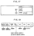
- Fig. 17 illustrates an example of a display for input apparatus selection according to the present embodiment.
- VTR 1 is the D2B address of the apparatus which is going to select an input apparatus
- VTR 2, CAM 1, and TV 1 are the D2B addresses of apparatuses which can be selected as an input apparatus.
- the PHOTO LIST key is a key which is operated to create a still image list.
- the cursor selection keys and channel Nos. serve the same purposes as those in Fig. 15.
- the VTR 1 selects apparatuses having a monitor based on logical addresses which depend on the categories of the apparatuses in the system. In the communication system in Fig. 15, only the TV 1 has a monitor portion which is not in use. Therefore, the TV 1 is selected. As a result, a still image list to be used for input selection at the VTR 1 is displayed on the TV 1.
- the VTR 1 requests all apparatuses in the system to output data.
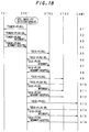
- Fig. 18 shows the exchange of a series of commands used for this purpose.
- the VTR 1 sends a request "Output from tuner portion to plug ?.” to the TV 1 (A1).
- the TV 1 responds "Output is accepted.
- Output is supplied from tuner portion to plug 1.”
- the "plug” is a virtual digital plug, e.g., a register for storing the number of the channel and bandwidth used for the input and output of the data provided at a digital interface 16. This plug is treated like a physical plug for the input and output of analog signals.
- the VTR 1 performs internal switching at the switch box therein to enable input from the plug 1 of the TV 1 to its own plug 1 and fetches one or several frames of the input data into an image memory (not shown) in a microcomputer 15 to create a still image list. Since the still image list is displayed on a screen which is divided into several parts, the data fetched into the image memory are frame images which have been thinned down depending on the number of the divisions. Further, correspondence between list Nos. on the still image list on the divided screen and D2B addresses is registered.
- the VTR 1 sends a request "Interrupt the output from tuner portion to plug 1.” to the TV 1 (A3).
- the TV 1 responds "Interruption is accepted.
- the output from tuner portion to plug 1 is interrupted.” (A4).
- Image output by the VTR 2, VTR 3, and CAM 1 are similarly added to the still image list according to procedures A5 through A16.
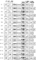
- Fig. 19 illustrates an example of a structure of a command packet used in the present embodiment.
- Fig. 20 illustrates an example of a structure of each command packet used in the procedures shown in Fig. 18.
- the "subdevice" in the abbreviated term SSDA/DSDA means a functional unit (deck, tuner, switch box, etc.) of an apparatus.
- all subdevices are switch boxes, and all commands are instructions to connect or disconnect the virtual digital plugs.
- Fig. 21 illustrates an example of the display of the still image list.
- Fig. 22 is a table showing correspondence between numbers on the still image list to be stored and the D2B addresses of the nodes outputting the still images.
- a still image 1 is an image from the TV 1. In this case, it is shown that no image has been output by the TV 1.
- a still image 2 is an image of the rising sun output by the VTR 1.
- a still image 3 is an image of a snowman output by the VTR 3.
- a still image 4 is an image of mountain scenery output by the CAM 1 3.
- Fig. 21 shows that no image has been created for the still images 5 - 9.
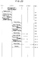
- Fig. 23 shows a series of commands exchanged in this case.
- the processes up to the creation of a list showing the TV 1, VTR 2, and VTR 3 by the VTR 1 (B1 - B12) are the same as A1 - A 12 in the above-described case (1).
- the CAM 1 When the VTR 1 requests the CAM 1 to output (B13), the CAM 1 responds "output disabled” because it is unable to reproduce due to the absence of a tape cassette (B14). Therefore, no reproduction image from the CAM 1 is included in the still image list.
- Fig. 24 illustrates an example of a structure of a command packet used in an embodiment of the invention.
- Fig. 24 illustrates an example of a structure of each command packet used in the procedures shown in Fig. 23.
- Fig. 25 illustrates an example of the display of the still image list.
- an arrangement for showing all of the apparatuses in the system on the still image list may be provided wherein, for example, a request for status information is issued to the CAM 1 in response to the reply "output disabled” to the request for output from the VTR 1 to the CAM 1 and, if a reply "No Medium In” is returned, the background is muted and an error message such as "No Cassette In” is displayed as shown in Fig. 26.
- the mountain scenery (the image reproduced by the CAM 1) is selected as input from the still image list.
- the mountainous scenery numbered 4 is selected from among the four still images numbered 1 - 4 displayed as in Fig. 21.
- the VTR 1 since the VTR 1 has stored the table showing correspondence between the still images and the D2B addresses of the apparatuses which reproduce the still images as shown in Fig. 22, the user can automatically perform input switching to receive the signal from the CAM 1 by simply selecting the still image numbered 4 without checking the D2B address of the apparatus reproducing the mountain scenery.
- a P1394 serial bus is used as the communication bus.
- other buses may be used as long as they have signal lines that allow signals to be freely exchanged between control lines and apparatuses.
- the present invention is not limited to systems wherein AV apparatuses are connected but may be applied to systems for connecting computers to allow the transmission and reception of data between them.
- all apparatuses are connected to a P1394 serial bus in the embodiments of the invention, for example, an analog TV may be connected to an analog AV output terminal of the VTR 1 to allow a still image list created at the VTR 1 to be displayed on the analog TV.
- the analog TV is treated as a subdevice of the VTR 1, procedures utilizing a command packet having the structure shown in Fig. 19 may be employed.
- a still image list is created by performing input switching to input images actually received by the tuner portion of a TV and images reproduced by the deck portions of VTR's in the above-described embodiments
- an arrangement may be made wherein a memory is provided in each tape cassette having images recorded therein to store the first one of the recorded images as a still image and the still image in the memory is transmitted to an apparatus which has issued a request for a still image to be listed.
- a command requesting output is transmitted based on a decision on the category of the apparatus to receive the command, e.g., a command to the TV 1 specifies output from the tuner 1 internally connected to the TV 1 by default because it is known that the TV 1 belong to a category "TV" in the above-described embodiments, it is possible to use a command "Output from any subdevice".
Abstract
Description
- In the field of systems for connecting a plurality of electronic apparatuses by a communication control bus on which control signals and data can coexist to allow communication between those electronic apparatuses, the present invention relates to a method of selecting an electronic apparatus in such a system to serve as a source of data when data is to be input to each of the electronic apparatuses from the desired electronic apparatus.
- Communication systems utilizing a P1394 serial bus have been proposed as communication systems in which electronic apparatuses such as a video tape recorder (hereinafter referred to as "VTR"), a television set (hereinafter referred to as "TV"), a VTR combined with a camera (hereinafter referred to as "CAM"), and a computer are connected by a communication control bus on which control signals and data can coexist to allow the transmission and reception of the control signals and data between such apparatuses.
- The details of such a serial bus is disclosed in "IEEE P1394 Serial Bus Specifications" (issued on October 14, 1993).
- An example of such a communication system will now be described with reference to Fig. 13. This communication system includes VTR's 1, 2, and 3 and a
CAM 1. Connection between theCAM 1 andVTR 1,VTR 1 andVTR 2, andVTR 2 andVTR 3 is established by P1394 serial buses. Since each of those electronic apparatuses has a function of repeating control signals and data on a P1394 serial bus, this system is equivalent to a communication system in which electronic apparatuses are connected to a common P1394 serial bus. - Fig. 14 is a block diagram showing a basic configuration of a VTR as an example of the electronic apparatuses in the communication system shown in Fig. 13. This VTR includes a
deck portion 1, atuner portion 2, anoperation portion 3 and adisplay portion 4 serving as a user interface, amicrocomputer 5 which performs the creation of packets to be described later, the storage of addresses and data, and the like, adigital interface 6 for interface with a P1394 serial bus, and aswitch box portion 7 for switching signals between thedeck portion 1,tuner portion 2, anddigital interface 6. If this electronic apparatus is a television set, a monitor portion and an amplifier portion are provided instead of thedeck portion 1 and thedisplay portion 14 is not included. If the apparatus is a CAM, a camera portion is provided instead of thetuner portion 2. - In the communication system shown in Fig. 13, communication is performed in predetermined communication cycles (e.g., 125 c. each) as shown in Fig. 15. It is possible to perform both of isochronous communication wherein data such as digital AV signals is continuously transmitted at a predetermined data rate and asynchronous communication wherein control signals such as connection control commands are irregularly transmitted as needed.
- A cycle start packet CSP is provided at the beginning of a communication cycle and is followed by a period which is set for transmission of isochronous communication packets. The communication packets are assigned channel Nos. 1, 2, 3, ..., N to allow simultaneous communication of a plurality of channels. For example, if communication from the
CAM 1 toVTR 1 is assigned the channel No. 1, theCAM 1 transmits isochronous communication packets having the channel No. 1 immediately after the cycle start packet CSP, and theVTR 1 monitors the bus and accepts the isochronous communication packets having the channel No. 1 to establish the communication. - If the channel No. 2 is assigned to communication from the
VTR 2 toVTR 3, the communication from theVTR 2 toVTR 3 can take place concurrently with the communication from theCAM 1 to theVTR 1. Then, asynchronous communication is carried out using a period that starts when the transmission of the isochronous communication packets is completed for all the channels to be transmitted and lasts until the next cycle start packet CSP. - In a communication system utilizing a P1394 serial bus, each electronic apparatus connected by the bus is automatically assigned a node ID (physical address) depending on the mode of connection. When an electronic apparatus is added to or removed from the communication system, the bus is reset and node ID's are automatically reassigned depending on the new mode of connection.
- In the communication system shown in Fig. 13, since each electronic apparatus is compatible with a D2B (domestic digital bus), it has a logical address (D2B address) which depends on the category it belongs to (
CAM 1,VTR 1,VTR 2, or VTR 4) in addition to the physical address as described above. In some communication systems, apparatuses such as computers, hard disc devices, etc. which are not D2B- compatible may be connected to the bus. The D2B addresses are characterized in that they are determined in the order in which apparatuses are initially connected to a communication system and are kept unchanged even after a bus reset for apparatuses which have not been removed from the system. - Therefore, even if the
CAM 1 is removed while theVTR 2 is recording a reproduction signal from theVTR 1, theVTR 1 andVTR 2 which are the D2B addresses of the source and destination, respectively, are kept unchanged, and the dubbing between the VTR's 1 and 2 can be continued. - In a communication system having the above-described configuration, when an operation is performed at the
operation portion 3 of each electronic apparatus to select an input apparatus, i.e., an electronic apparatus from which input of a digital AV signal is desired (hereinafter referred to as "input apparatus selection operation"), the apparatus issues an inquiry to all other electronic apparatuses in the system using an asynchronous communication packet to know whether they are D2B-compatible and displays on thedisplay portion 4 the D2B addresses of the electronic apparatuses other than itself which have been identified as D2B-compatible apparatuses. - For example, the
VTR 3 in Fig. 13 will display as shown in Fig. 16. This is an example of a display using the fluorescent tube of thedisplay portion 4. In Fig. 16, "VTR 3" is the logical address of theVTR 3 itself according to its category. The window "input apparatus" shows the categorized logical addresses of the apparatuses which are candidates for the selection of an input apparatus. In this case, the display showsVTR 1,VTR 2, andCAM 1. - Further, operation keys for moving the cursor and an execution key are displayed on the right of the window showing the input apparatuses. The user selects an input apparatus by moving the cursor to the position of the desired apparatus and by designating the execution key while monitoring the contents of the display. The channels shown in Fig. 16 are the channels of the television broadcasts selected by the VTR's and the tuner of the television.
- An example of such a communication system will now be described with reference to Fig. 27. This communication system includes a
TV 1, VTR's 1, 2, 3, and aCAM 1. The connection between theTV 1 andVTR 1,VTR 1 andVTR 2,VTR 2 andVTR 3, andVTR 3 andCAM 1 is established by P1394 serial buses capable of transmitting a mixture of control signals and data. Since each of the electronic apparatuses has a function of relaying the control signals and data on the P1394 serial bus, this system is equivalent to a communication system wherein a electronic apparatuses are connected to a common P1394 serial bus. - Fig. 28 is a block diagram showing a basic configuration of a VTR as an example of the electronic apparatuses in the communication system shown in Fig. 27. This VTR includes a
deck portion 11, atuner portion 12, anoperation portion 13 and adisplay portion 14 serving as a user interface, amicrocomputer 15 which performs the creation of packets to be described later, the storage of addresses and data, and the like, adigital interface 16 for interface with a P1394 serial bus, and aswitch box portion 17 for switching signals between thedeck portion 11,tuner portion 12, anddigital interface 16. If this electronic apparatus is a television set, a monitor portion and an amplifier portion are provided instead of thedeck portion 11 and thedisplay portion 14 is not included. If the apparatus is a CAM, a camera portion is provided instead of thetuner portion 12. - In the communication system shown in Fig. 27, communication is performed in predetermined communication cycles (eg 125 µsec. each) as shown in Fig. 15. It is possible to perform both of isochronous communication wherein data such as digital AV signals is continuously transmitted at a predetermined data rate and asynchronous communication wherein control signals such as connection control commands are irregularly transmitted as needed.
- A cycle start packet CSP is provided at the beginning of a communication cycle and is followed by a period which is set for transmission of isochronous communication packets. The communication packets are assigned channel Nos. 1, 2, 3, ..., N to allow simultaneous communication of a plurality of channels. For example, if communication from the
CAM 1 toVTR 1 is assigned the channel No. 1, theCAM 1 transmits isochronous communication packets having the channel No. 1 immediately after the cycle start packet CSP, and theVTR 1 monitors the bus and accepts the isochronous communication packets having the channel No. 1 to establish the communication. - If the channel No. 2 is assigned to communication from the
VTR 2 toVTR 3, the communication from theVTR 2 toVTR 3 can take place concurrently with the communication from theCAM 1 toVTR 1. The asynchronous communication is carried out using a period that starts when the transmission of the isochronous communication packets is completed for all the channels to be transmitted and lasts until the next cycle start packet CSP. - In a communication system utilizing a P1394 serial bus, each electronic apparatus connected by the bus is automatically assigned a node ID (physical address) depending on the mode of connection. When an electronic apparatus is added to or removed from the communication system, the bus is reset and node ID's are automatically reassigned depending on the new mode of connection.
- In the communication system shown in Fig. 27, since each electronic apparatus is compatible with a D2B, it has a D2B address in addition to the physical address as described above. In some communication systems, apparatuses such as computers, hard disc devices, etc. which are not D2B- compatible may be connected to the bus. The D2B addresses are characterized in that they are determined in the order in which apparatuses are initially connected to a communication system and are kept unchanged even after a bus reset for apparatuses which have not been removed from the system. Therefore, even if the
CAM 1 is removed while theVTR 2 is recording a reproduction signal from theVTR 1,VTR 1 andVTR 2 which are the D2B addresses of the source and destination, respectively, are kept unchanged, and the dubbing between VTR's 1 and 2 can be continued. - In a communication system having the above-described configuration, when the input apparatus selection operation is performed at the
operation portion 13 of each electronic apparatus, the apparatus issues an inquiry to all other electronic apparatuses in the system using an asynchronous communication packet to know whether they are D2B-compatible and displays on thedisplay portion 14 the D2B addresses of the electronic apparatuses other than itself which have been identified as D2B-compatible apparatuses. - For example, the
VTR 3 in Fig. 27 will display as shown in Fig. 16. This is an example of a display using the fluorescent tube of thedisplay portion 14. In Fig. 27,VTR 3 is the logical address of theVTR 3 itself according to its category. The window "input apparatus" shows the categorized logical addresses of the apparatuses which are candidates for the selection of an input apparatus. In this case, the display showsVTR 1,VTR 2, andCAM 1. Further, operation keys for moving the cursor and an execution key are displayed on the right of the window showing the input apparatuses. The user selects an input apparatus by moving the cursor to the position of the desired apparatus and by designating the execution key while monitoring the contents of the display. The channels shown in Fig. 16 are the channels of the television broadcasts selected by the VTR's and the tuner of the television. - However, according to the conventional method of selecting an input apparatus wherein all apparatuses having a D2B address are displayed, any apparatus in the system is displayed as a candidate input apparatus even if it is supposed to be disabled from outputting information signals for some reason, e.g., a state wherein it is not loaded with a video tape or it is receiving the input of information signals from another apparatus. This can cause erroneous selection of an input apparatus.
- Further, if a desired apparatus is selected from among candidate input apparatuses including apparatuses which can not be an input apparatus, the selection operation by a user can take a long time because many apparatuses have to be examined for selection.
- In addition, according to the above-described input apparatus selection method, an input apparatus is selected based on the user's understanding of the D2B address thereof. As a result, erroneous selection can be caused by a change in the actual D2B address of the desired input apparatus which has not been recognized by the user.
- As described above, a D2B address is not reassigned each time a bus reset occurs unlike the node ID. However, if a plurality of apparatuses on a system are removed and some of the removed apparatuses are connected to the system again, the D2B addresses may be changed. This is because the D2B addresses of apparatuses in the same category are assigned in an ascending order, e.g., the D2B addresses
VTR 1,VTR 2, andVTR 3 are assigned in the order listed. - The present invention has been conceived to solve the problems as described above, and it is an object of the invention to provide a method of selecting input apparatuses wherein it is possible to display apparatuses which can output information signals as candidate input apparatuses.
- It is another object of the invention to provide a method of selecting input apparatuses wherein a desired apparatus can be correctly selected even when the assignment of the D2B addresses has been changed.
- In order to solve the above-described problems, according to the present invention, in a system wherein a plurality of electronic apparatuses are connected by a communication control bus for communication between those electronic apparatuses, each of the electronic apparatuses selects an input apparatus by sending an inquiry to all other apparatuses in the system on whether they can output data, displaying the apparatuses which respond that output is possible as candidate input apparatuses, and selecting the input apparatus from among the candidate input apparatuses.
- Further, for an electronic apparatus which can not output data, the present invention makes it possible to display the reason for the impossibility to output data. The reason for the impossibility to output data may be displayed at either the apparatus incapable of outputting data or the apparatus which is to select an input apparatus.
- In order to solve the above-described problems, according to the present invention, in a system wherein a plurality of electronic apparatuses are connected by a communication control bus for communication between those electronic apparatuses, each of the electronic apparatuses selects an input apparatus by causing other electronic apparatuses in the system to transmit image data, creating a list constituted by still images from the image data, displaying the still image list, and selecting the input apparatus with reference to the displayed still image list.
- If the still image list is created from images of one frame each for respective apparatuses, one frame of image will be displayed for each apparatus. If the still image list is created from data of plural frames for each apparatus, plural frames of image, i.e., a dynamic image for a short period of time, will be displayed for each apparatus. This results in an increase in the amount of image data available for reference in selecting an input apparatus, allowing reliable selection.
- While an electronic apparatus incapable of transmitting image data does not need to be included in the still image list, a still image indicating the reason why the transmission of image data is impossible may be included in the list to allow the user to take an action to enable the transmission of image data from the still image list.
- In addition, after the creation of the still image list, it is possible to cause other electronic apparatus in the system to sequentially transmit image data for a predetermined period of time again. Such image data can be also referred to during the selection of an input apparatus. This makes it possible to select an input apparatus with reference to dynamic images using only the minimum amount of image memory required for the creation of the still image list.
- According to the present invention, when an input apparatus is to be selected, only apparatuses which can actually output data are displayed as candidate input apparatuses. This makes it possible to prevent an apparatus incapable of outputting data from being selected by mistake. Further, since only apparatuses which can be actually selected as input apparatuses are displayed, the time required for selecting operation is reduced even if the input apparatuses are sequentially selected through an operation such as toggling.
- Further, for an apparatus which can not be an input apparatus, the present invention allows the reason to be displayed. This makes it possible for a user to select a desired input apparatus even if it is disabled from outputting data by taking an action to eliminate the cause of such impossibility provided it is not a failure of the apparatus.
- The present invention allows a user to select an input apparatus with reference to a displayed still image list. As a result, even if the D2B address of the input apparatus that the user has initially recognized is different from the actual D2B address at the time of selection, the user can select the input apparatus by finding the desired image without the need for checking the D2B address of the desired apparatus each time selection is attempted. This not only prevents erroneous selection but also appears to be user friendly because he or she only needs to select the desired image from the list showing various still images without being annoyed by the concept of the selection of an input apparatus.
- As described above in detail, the present invention prevents an apparatus which can not provide input from being selected by mistake because an inquiry is sent to other apparatuses in the system on whether they can output data to display apparatuses which can actually provide the input.
- The operability during selection is also improved in that the maximum number of operations required for selection can be limited to the number of apparatuses which can provide input even if selection is performed by a toggle operation wherein candidate input apparatuses are sequentially examined one by one.
- Further, for an apparatus which can not be an input apparatus, the present invention allows the reason to be displayed. This makes it possible to enable such an apparatus which is supposed to be disabled from inputting depending on the reason based on the user's decision.
- As described above, according to the present invention, an input apparatus is selected based on image data output by each electronic apparatus. This not only prevents erroneous selection where the D2B address of a desired apparatus has been changed but also appears to be user friendly because he or she is not annoyed by the concept of the selection of an input apparatus.
- The invention will be further described by way of non-limitative example with reference to the accompanying drawings, in which:-
- Fig. 1 illustrates an example of command transmission/ reception procedures used in an embodiment of the invention during selection of input apparatuses.
- Fig. 2 illustrates an example of a structure of a command packet used in an embodiment of the invention.
- Fig. 3 illustrates an example of a structure of each command packet used in the procedures shown in Fig. 1.
- Fig. 4 illustrates an example of the display of candidate input apparatuses on a
VTR 1. - Fig. 5 illustrates another example of the command transmission/reception procedures used in an embodiment of the invention during selection of input apparatuses.
- Fig. 6 illustrates an example of a structure of each command packet used in the procedures shown in Fig. 5.
- Fig. 7 illustrates an example of the display of candidate input apparatuses on a
VTR 2. - Fig. 8 illustrates an example of a warning message displayed on
VTR 1. - Fig. 9 illustrates still another example of the command transmission/reception procedures used in an embodiment of the invention during selection of input apparatuses.
- Fig. 10 illustrates an example of a structure of each command packet used in the procedures shown in Fig. 9.
- Fig. 11 illustrates an example of the display of candidate input apparatuses on a
VTR 3. - Fig. 12 illustrates another example of the display of candidate input apparatuses on
VTR 3. - Fig. 13 illustrates an example of an audio-visual communication system utilizing a P1394 serial bus.
- Fig. 14 illustrates a schematic configuration of a VTR in the communication system shown in Fig. 13.
- Fig. 15 illustrates an example of a communication cycle in a communication system utilizing P1394 serial buses.
- Fig. 16 illustrates an example of a display for input apparatus selection in the communication system shown in Fig. 13.
- Fig. 17 illustrates an example of a display for input apparatus selection in an embodiment of the present invention.
- Fig. 18 illustrates an example of command transmission/ reception procedures used in the embodiment during the creation of a still image list.
- Fig. 19 illustrates an example of a structure of a command packet used in an embodiment of the invention.
- Fig. 20 illustrates an example of a structure of each command packet used in the procedures shown in Fig. 18.
- Fig. 21 illustrates an example of the display of a still image list created according to the procedure shown in Fig. 18.
- Fig. 22 is a table showing correspondence between numbers on a still image list and the D2B addresses of the apparatuses outputting the still images.
- Fig. 23 illustrates another example of the command transmission/reception procedures used in the embodiment during the creation of a still image list.
- Fig. 24 illustrates an example of a structure of a command packet used in an embodiment of the invention.
- Fig. 24 illustrates an example of a structure of each command packet used in the procedures shown in Fig. 23.
- Fig. 25 illustrates an example of the display of a still image list created according to the procedures shown in Fig. 23.
- Fig. 26 illustrates an example of the display of a still image list created according to the procedures shown in Fig. 23 with a partial modification thereto.
- Fig. 27 illustrates an example of a communication system wherein a plurality of apparatuses are connected by P1394 serial buses.
- Fig. 28 illustrates a schematic configuration of a VTR in the communication system shown in Fig. 27.
- An embodiment of the present invention will now be described with reference to the drawings. The present embodiment addresses selection of an input apparatus during communication between the apparatuses in the communication system shown in Fig. 13 with reference to the following cases.
- (1) All of the VTR's 1, 2, and 3 and the
CAM 1 are not performing any operation. - (2) The
VTR 2 records AV (audio-visual) signals reproduced by theCAM 1 concurrently with the recording of the AV signal from theCAM 1 by theVTR 1. - (3) The
VTR 3 requests theVTR 2 to output AV signals while the VTR's 1 and 2 are recording AV signals reproduced by theCAM 1. - (1) When all of the VTR's 1, 2, and 3 and the
CAM 1 are not performing any operation, if an input apparatus selection operation is enabled at theVTR 1 to input AV signals from theCAM 1, an inquiry is issued from theVTR 1 to all other apparatuses in the system on whether they can output data. Fig. 1 shows an example of procedures for the exchange of such inquiries and responses. First, theVTR 1 asks theCAM 1 whether it can perform digital output (A1). TheCAM 1 responds "Yes" (A2). Similarly, theVTR 1 asks the VTR's 2 and 3 whether they can perform digital output, and receives a response "Yes" from each of them (A3 - A6). - Fig. 2 illustrates an example of a structure of a command packet used in the present embodiment, and Fig. 3 illustrates examples of the command packets used in the procedures A1 through A6 in Fig. 1. The "subdevice" in the abbreviated term SSDA/DSDA in Fig. 2 refers to a functional unit (deck, tuner, etc.) in an apparatus. "Dummy" represents a location intended for the data of a response, and "OK" indicates that a response has been sent against the inquiry command.
- In this case, since all of the
VTR 2,VTR 3, andCAM 1 can output AV signals, the display portion of theVTR 1 displays all other apparatuses in the system, i.e., theVTR 2,VTR 3, andCAM 1 as shown in Fig. 4. If theCAM 1 is selected, connection is established between theCAM 1 andVTR 1. At this time, if theCAM 1 is set to a reproduction mode, AV signals reproduced by theCAM 1 are input to theVTR 1. If theCAM 1 is not reproducing, a monitor (not shown) connected to the output of theVTR 1 will display no image and show a black screen. Similarly, when input apparatus selection is enabled at theVTR 2, theVTR 1,VTR 3, andCAM 1 are displayed as candidate input apparatuses; when input apparatus selection is enabled at theVTR 3, theVTR 1,VTR 2, andCAM 1 are displayed as candidate input apparatuses; and, when input apparatus selection is enabled at theCAM 1, theVTR 1,VTR 2, andVTR 3 are displayed as candidate input apparatuses. - Although Fig. 1 shows that the inquiry on the possibility of data output is sequentially followed by the reception of the response thereto for each apparatus, it is possible to employ a procedure wherein the inquiry is first issued to all apparatuses simultaneously and then the responses are received.
- (2) In the case that the
VTR 2 records AV signals reproduced by theCAM 1 concurrently with the recording of the AV signal from theCAM 1 by theVTR 1, theVTR 1 has already selected theCAM 1 and records the AV signal reproduced by theCAM 1 if it is set to a recording mode. If input apparatus selection is enabled at theVTR 2 in such a state to record the AV signals from theCAM 1, an inquiry is issued from theVTR 2 to all other apparatuses in the system simultaneously on whether they can output data. - Fig. 5 illustrates examples of commands used for this inquiry and Fig. 6 illustrates examples of structures of the command packets. In this case, since the
VTR 1 responds that it is recording (B4), it is determined to be unable to output data. Therefore, as shown in Fig. 7, theVTR 3 andCAM 1 are displayed as candidate input apparatuses on the display portion of theVTR 2 using a fluorescent tube. If theCAM 1 is selected and theVTR 2 is set to a recording mode, theVTR 2 can also record the AV signals reproduced by theCAM 1. At the same time, the display portion of theVTR 1 displays a warning message "recording" as shown in Fig. 8 which allows the user to recognize that theVTR 1 can not be an input apparatus. - (3) When the
VTR 3 requests theVTR 2 to output AV signals while the VTR's 1 and 2 are recording AV signals reproduced by theCAM 1. if an input apparatus selection operation is enabled at theVTR 3 to cause the AV signals reproduced by theVTR 2 to be input to theVTR 3, an inquiry is issued from theVTR 3 to all other apparatuses in the system on whether they can output data. - Fig. 9 illustrates examples of commands used for this inquiry and Fig. 10 illustrates examples of structures of the command packets. In this case, since the
VTR 1 andVTR 2 respond that they are recording (C4 and C6), only theCAM 1 is displayed as a candidate input apparatus using a fluorescent tube on the display portion of theVTR 3. The display portions of bothVTR 1 andVTR 2 display a warning message "recording" as in Fig. 8 using a fluorescent tube, which makes it possible to recognize that they can not be an input apparatus. - Therefore, the
VTR 3 can not receive input from theVTR 2. However, if theVTR 3 must receive input from theVTR 2 even by interrupting the recording operation between theCAM 1 andVTR 2, theVTR 2 can be also displayed as a candidate input apparatus using the fluorescent tube as shown in Fig. 12 by setting theVTR 2 to a stop mode according to the warning message "recording" to interrupt the recording operation between theCAM 1 andVTR 2. If theVTR 2 is then selected, theVTR 3 can record the AV signals reproduced by theVTR 2. - Although a P1394 serial bus is used as a communication control bus in the present embodiment, other digital buses may be used as long as they can carry a mixture of control signals and data.
- The description so far has addressed the case wherein either input or output is selected. Where input and output can be simultaneously performed, warning messages such as "recording" are output only when the allowable number of inputs and outputs (the number of input/output plugs) specific to each apparatus is exceeded.
- The present invention is not limited to communication systems wherein AV apparatuses are connected but may be applied to systems which transmit and receive to and from a computer connected thereto. Although the description has been made with reference to a fluorescent display tube of a VTR, selection of an input apparatus may be performed using an LCD of a VTR or a screen of a television set and the like.
- Further, according to the present embodiment, an apparatus which selects an input apparatus displays only apparatuses capable of supplying input thereto, and the warning message is displayed at apparatuses which can not output data. However, an arrangement may be made in which the warning message is displayed on the apparatus which selects an input apparatus, i.e., all apparatuses in the system are displayed including those which can be selected and those which can not be selected and the warning message is displayed for the apparatuses which can not be selected.
- In addition, although only the warning message "recording" has been described as an example, various warning messages may be displayed including "no tape", "end of tape", etc. which are messages regarding the state of the tape and "power supply off".
- Although a dedicated command is used for inquiry in the present embodiment, an alternative method for inquiry command transmission may be used wherein input apparatus selection is performed by transmitting a output command specified on a subdevice basis, e.g., "input from the deck" or "input from the tuner", to other apparatuses in the system simultaneously; an inquiry is sent only to apparatuses which respond that they reject the request for input about the reason for such rejection to allow display of a specific warning message such as "inputting to the deck".
- Another embodiment of the present invention will now be described with the drawings. The present embodiment addresses an example of input apparatus selection utilizing a list constituted by still images representing apparatuses during communication between the apparatuses in the communication system shown in Fig. 15.
- Fig. 17 illustrates an example of a display for input apparatus selection according to the present embodiment. In Fig. 17,
VTR 1 is the D2B address of the apparatus which is going to select an input apparatus, andVTR 2,CAM 1, andTV 1 are the D2B addresses of apparatuses which can be selected as an input apparatus. The PHOTO LIST key is a key which is operated to create a still image list. The cursor selection keys and channel Nos. serve the same purposes as those in Fig. 15. - (1) A description will be made on a case wherein selection is performed at the
VTR 1 using the still image list when all of theTV 1,VTR 2,VTR 3, andCAM 1 can output data. In this case, the still image list is output to and displayed on a monitor. The user first points to the PHOTO LIST key at the fluorescent tube display portion of theVTR 1 as shown in Fig. 17. - The
VTR 1 selects apparatuses having a monitor based on logical addresses which depend on the categories of the apparatuses in the system. In the communication system in Fig. 15, only theTV 1 has a monitor portion which is not in use. Therefore, theTV 1 is selected. As a result, a still image list to be used for input selection at theVTR 1 is displayed on theTV 1. - Thereafter, the
VTR 1 requests all apparatuses in the system to output data. Fig. 18 shows the exchange of a series of commands used for this purpose. First, theVTR 1 sends a request "Output from tuner portion to plug ?." to the TV 1 (A1). TheTV 1 responds "Output is accepted. Output is supplied from tuner portion to plug 1." (A2). The "plug" is a virtual digital plug, e.g., a register for storing the number of the channel and bandwidth used for the input and output of the data provided at adigital interface 16. This plug is treated like a physical plug for the input and output of analog signals. - In response to this, the
VTR 1 performs internal switching at the switch box therein to enable input from theplug 1 of theTV 1 to itsown plug 1 and fetches one or several frames of the input data into an image memory (not shown) in amicrocomputer 15 to create a still image list. Since the still image list is displayed on a screen which is divided into several parts, the data fetched into the image memory are frame images which have been thinned down depending on the number of the divisions. Further, correspondence between list Nos. on the still image list on the divided screen and D2B addresses is registered. - When the output from the tuner of the
TV 1 has been added to the still image list. the bus is immediately released to prevent the bus from being occupied. For this purpose, theVTR 1 sends a request "Interrupt the output from tuner portion to plug 1." to the TV 1 (A3). TheTV 1 responds "Interruption is accepted. The output from tuner portion to plug 1 is interrupted." (A4). - Image output by the
VTR 2,VTR 3, andCAM 1 are similarly added to the still image list according to procedures A5 through A16. - Fig. 19 illustrates an example of a structure of a command packet used in the present embodiment. Fig. 20 illustrates an example of a structure of each command packet used in the procedures shown in Fig. 18. The "subdevice" in the abbreviated term SSDA/DSDA means a functional unit (deck, tuner, switch box, etc.) of an apparatus. In Fig. 20, all subdevices are switch boxes, and all commands are instructions to connect or disconnect the virtual digital plugs.
- When the creation of a still image list is completed as described above, the still image list is displayed on the monitor portion of the
TV 1. Fig. 21 illustrates an example of the display of the still image list. Fig. 22 is a table showing correspondence between numbers on the still image list to be stored and the D2B addresses of the nodes outputting the still images. In Fig. 21, astill image 1 is an image from theTV 1. In this case, it is shown that no image has been output by theTV 1. Astill image 2 is an image of the rising sun output by theVTR 1. Astill image 3 is an image of a snowman output by theVTR 3. Astill image 4 is an image of mountain scenery output by theCAM 1 3. Fig. 21 shows that no image has been created for the still images 5 - 9. In the example of display of a still image list in Fig. 21, when one frame of image is fetched into the image memory for each apparatus, one frame is displayed for each apparatus. If a plurality of frames of image are fetched for each apparatus, a dynamic image for a short period of time can be displayed for each apparatus by sequentially switching the plurality of frames. - (2) A description will be made on a case wherein the
CAM 1 has no tape cassette loaded therein. - Fig. 23 shows a series of commands exchanged in this case. The processes up to the creation of a list showing the
TV 1,VTR 2, andVTR 3 by the VTR 1 (B1 - B12) are the same as A1 -A 12 in the above-described case (1). - When the
VTR 1 requests theCAM 1 to output (B13), theCAM 1 responds "output disabled" because it is unable to reproduce due to the absence of a tape cassette (B14). Therefore, no reproduction image from theCAM 1 is included in the still image list. - Fig. 24 illustrates an example of a structure of a command packet used in an embodiment of the invention.
- Fig. 24 illustrates an example of a structure of each command packet used in the procedures shown in Fig. 23. Fig. 25 illustrates an example of the display of the still image list. In the example shown in Fig. 24, only apparatuses capable of outputting image data output still images to be added to the list. Therefore, a user can not discriminate between apparatuses unable to output and apparatuses which are not in the system. In order to solve this problem, an arrangement for showing all of the apparatuses in the system on the still image list may be provided wherein, for example, a request for status information is issued to the
CAM 1 in response to the reply "output disabled" to the request for output from theVTR 1 to theCAM 1 and, if a reply "No Medium In" is returned, the background is muted and an error message such as "No Cassette In" is displayed as shown in Fig. 26. - Although input switching is performed according to the images (each consisting of one or plural frames) in the displayed still image list in the present embodiment, an alternative method may be used wherein the still images are sequentially created for all apparatuses as in the abovedescribed cases (1) and (2); when a still image list showing all apparatuses is complete, a request for output is issued to the apparatuses in the order they were listed; each apparatus outputs the dynamic image available at the time of the request for several seconds and releases the bus to allow the next apparatus to output a dynamic image. In this case, each of the numbered images displayed as the still image list is switched to a dynamic image if the apparatus is outputting a dynamic image. This makes it possible to select an input apparatus with reference to such dynamic images using the minimum amount of image memory required for the creation of the still image list.
- (3) A description will now be made on a case wherein the mountain scenery (the image reproduced by the CAM 1) is selected as input from the still image list. For example, the mountainous scenery numbered 4 is selected from among the four still images numbered 1 - 4 displayed as in Fig. 21. Then, since the
VTR 1 has stored the table showing correspondence between the still images and the D2B addresses of the apparatuses which reproduce the still images as shown in Fig. 22, the user can automatically perform input switching to receive the signal from theCAM 1 by simply selecting the still image numbered 4 without checking the D2B address of the apparatus reproducing the mountain scenery. - In the above-described embodiments of the present invention, a P1394 serial bus is used as the communication bus. However, other buses may be used as long as they have signal lines that allow signals to be freely exchanged between control lines and apparatuses.
- The present invention is not limited to systems wherein AV apparatuses are connected but may be applied to systems for connecting computers to allow the transmission and reception of data between them. Further, although all apparatuses are connected to a P1394 serial bus in the embodiments of the invention, for example, an analog TV may be connected to an analog AV output terminal of the
VTR 1 to allow a still image list created at theVTR 1 to be displayed on the analog TV. In this case, if the analog TV is treated as a subdevice of theVTR 1, procedures utilizing a command packet having the structure shown in Fig. 19 may be employed. - Although a still image list is created by performing input switching to input images actually received by the tuner portion of a TV and images reproduced by the deck portions of VTR's in the above-described embodiments, an arrangement may be made wherein a memory is provided in each tape cassette having images recorded therein to store the first one of the recorded images as a still image and the still image in the memory is transmitted to an apparatus which has issued a request for a still image to be listed.
- Although a command requesting output is transmitted based on a decision on the category of the apparatus to receive the command, e.g., a command to the
TV 1 specifies output from thetuner 1 internally connected to theTV 1 by default because it is known that theTV 1 belong to a category "TV" in the above-described embodiments, it is possible to use a command "Output from any subdevice". - The applicant has made the following applications which are related to the present application.
European Patent Publication No. 0614297
Japanese Patent Application No. 05126682
Japanese Patent Application No. 05200056
Japanese Patent Application No. 06051246
Japanese Patent Application No. 06134940
Japanese Patent Application No. 06242255
Applications for U.S. patent for the above six inventions are pending. (The above applications are owned by the assignee of the present invention and hereby incorporated by reference.) - While the present invention has been illustrated and described in connection with the preferred embodiments, it is not to be limited to the particular structures shown. It should be understood by those skilled in the art that various changes and modifications may be made within the purview of the appended claims without departing from the spirit and scope of the invention in its broader aspects.
Claims (16)
- A method of connecting a plurality of electronic apparatus by a communication control bus to allow communication between said electronic apparatuses comprising the steps of:
sending an inquiry from each of the electronic apparatus which is to select an input apparatus to all other electronic apparatuses in the system on whether they can output data;
displaying only electronic apparatuses which have responded that they can output as candidate input apparatuses; and
selecting an input apparatus from among said candidate input apparatuses. - The method according to Claim 1, wherein, for electronic apparatuses which can not output data, an indication of the reason for such impossibility is displayed.
- The method according to Claim 2, wherein the indication of the reason for the impossibility of data output is displayed at said electronic apparatuses which can not output data.
- The method according to Claim 2 or 3, wherein the indication of the reason for the impossibility of data output is displayed at the apparatus selecting an input apparatus.
- A method of connecting a plurality of electronic apparatus by a communication control bus to allow communication between said electronic apparatuses comprising the steps of:
creating a list consisting of still images at each of the electronic apparatuses which is to select an input apparatus from image data transmitted by other apparatuses in the system;
displaying said still image list; and
selecting an input apparatus with reference to said displayed still image list. - The method according to Claim 5, wherein the still image list is created from plural frames of image data for each of the electronic apparatuses.
- The method according to Claim 6, wherein, for electronic apparatuses which can not output data, a still image list is created to show the reason for such impossibility.
- The method according to Claim 7, further comprising the steps of causing other electronic apparatuses in the system to sequentially transmit image data again for a predetermined period of time after the creation of the still image list and selecting an input apparatus with reference to said image data.
- Electronic apparatuses which communicate image data therebetween comprising:
an interface for controlling the input and output of image signals, and
a control means for performing control so that an inquiry is sent from each of the electronic apparatuses which is to select an input apparatus to all other electronic apparatuses in the system on whether they can output data; only electronic apparatuses which have responded that they can output as candidate input apparatuses are displayed; and an input apparatus is selected from among said candidate input apparatuses. - The electronic apparatuses according to Claim 9, wherein, for electronic apparatuses which can not output data, an indication of the reason for such impossibility is displayed.
- The electronic apparatuses according to Claim 9 or 10, wherein an indication of the reason for the impossibility of data output is displayed at said electronic apparatuses which can not output data.
- The electronic apparatuses according to Claim 9, 10 or 11, wherein an indication of the reason for the impossibility of data output is displayed at the apparatus selecting an input apparatus.
- Electronic apparatuses which communicate image data therebetween comprising:
an interface for controlling the input and output of image signals, and
a control means for performing control so that a list consisting of still images is created at each of the electronic apparatuses which is to select an input apparatus from image data transmitted by other apparatuses in the system; said still image list is displayed; and an input apparatus is selected with reference to said displayed still image list. - The electronic apparatuses according to Claim 13, wherein the still image list is created from plural frames of image data for each of the electronic apparatuses.
- The electronic apparatuses according to Claim 14, wherein, for electronic apparatuses which can not output data, a still image list is created to show the reason for such impossibility.
- The electronic apparatuses according to Claim 15, further comprising a means for causing other electronic apparatuses in the system to sequentially transmit image data again for a predetermined period of time after the creation of the still image list and selecting an input apparatus with reference to said image data.
Applications Claiming Priority (3)
| Application Number | Priority Date | Filing Date | Title |
|---|---|---|---|
| JP200183/94 | 1994-08-02 | ||
| JP20018394 | 1994-08-02 | ||
| JP20018394A JP3520572B2 (en) | 1994-08-02 | 1994-08-02 | Input device selection method |
Publications (2)
| Publication Number | Publication Date |
|---|---|
| EP0696109A2 true EP0696109A2 (en) | 1996-02-07 |
| EP0696109A3 EP0696109A3 (en) | 1999-10-27 |
Family
ID=16420181
Family Applications (1)
| Application Number | Title | Priority Date | Filing Date |
|---|---|---|---|
| EP95305343A Withdrawn EP0696109A3 (en) | 1994-08-02 | 1995-07-31 | Method of selecting input apparatus |
Country Status (6)
| Country | Link |
|---|---|
| US (1) | US5760698A (en) |
| EP (1) | EP0696109A3 (en) |
| JP (1) | JP3520572B2 (en) |
| KR (1) | KR100391405B1 (en) |
| CN (1) | CN1087544C (en) |
| CA (1) | CA2154949C (en) |
Cited By (4)
| Publication number | Priority date | Publication date | Assignee | Title |
|---|---|---|---|---|
| EP0976242A1 (en) * | 1997-04-03 | 2000-02-02 | Sony Electronics Inc. | Display with one or more display windows and placement dependent cursor and function control |
| EP1137222A1 (en) * | 1999-10-04 | 2001-09-26 | Sony Corporation | Method of controlling device, transmission device, and medium |
| EP1202464A1 (en) * | 2000-10-27 | 2002-05-02 | Canon Kabushiki Kaisha | Method and device for managing a communication network |
| WO2002089468A1 (en) | 2001-04-20 | 2002-11-07 | Sony Corporation | Video signal selector apparatus and control method thereof |
Families Citing this family (35)
| Publication number | Priority date | Publication date | Assignee | Title |
|---|---|---|---|---|
| US20020091850A1 (en) | 1992-10-23 | 2002-07-11 | Cybex Corporation | System and method for remote monitoring and operation of personal computers |
| JP3561969B2 (en) * | 1994-08-30 | 2004-09-08 | ソニー株式会社 | Editing method and editing control device |
| US5721842A (en) | 1995-08-25 | 1998-02-24 | Apex Pc Solutions, Inc. | Interconnection system for viewing and controlling remotely connected computers with on-screen video overlay for controlling of the interconnection switch |
| US5956081A (en) * | 1996-10-23 | 1999-09-21 | Katz; Barry | Surveillance system having graphic video integration controller and full motion video switcher |
| JP3735942B2 (en) * | 1996-06-04 | 2006-01-18 | ソニー株式会社 | COMMUNICATION CONTROL METHOD, COMMUNICATION SYSTEM AND ELECTRONIC DEVICE USED FOR THE SAME |
| JP3783282B2 (en) * | 1996-06-04 | 2006-06-07 | ソニー株式会社 | COMMUNICATION CONTROL METHOD, COMMUNICATION SYSTEM AND ELECTRONIC DEVICE USED FOR THE SAME |
| CA2216573C (en) * | 1996-10-01 | 2006-03-14 | Sony Corporation | Digital tuner having ieee 1394 serial bus interface for providing a plurality of selected programs as a functional unit |
| EP0841776A1 (en) * | 1996-11-12 | 1998-05-13 | Sony Corporation | Communication methods and electronic apparatus thereof |
| JPH10155121A (en) * | 1996-11-21 | 1998-06-09 | Matsushita Electric Ind Co Ltd | Video display device |
| WO1998043416A1 (en) * | 1997-03-21 | 1998-10-01 | Hitachi, Ltd. | Av apparatus, method for using av apparatus, and av system |
| ID27676A (en) * | 1997-09-11 | 2001-04-19 | Sony Corp | ELECTRONIC EQUIPMENT |
| DE69937919T9 (en) * | 1998-02-25 | 2009-04-30 | Nec Corp. | Network with a network management system for connecting several devices for storing and reproducing television programs |
| JP3606423B2 (en) * | 1998-05-21 | 2005-01-05 | 株式会社ケンウッド | AV system with IEEE1394 serial bus |
| KR100304644B1 (en) * | 1998-06-19 | 2001-11-02 | 윤종용 | Apparatus and method for transmitting informtion via network |
| US6119243A (en) * | 1998-07-06 | 2000-09-12 | Intel Corp. | Architecture for the isochronous transfer of information within a computer system |
| JP2000090575A (en) * | 1998-09-14 | 2000-03-31 | Toshiba Corp | Network integrated management device and method |
| CA2345084C (en) | 1998-09-22 | 2004-11-02 | Cybex Computer Products Corporation | System for accessing personal computers remotely |
| US6947398B1 (en) * | 1998-11-13 | 2005-09-20 | Lucent Technologies Inc. | Addressing scheme for a multimedia mobile network |
| WO2001091504A1 (en) * | 2000-05-22 | 2001-11-29 | Sony Corporation | Data transmission method, data transmission system, and data transmission apparatus |
| JP2002094604A (en) * | 2000-09-12 | 2002-03-29 | Canon Inc | Terminal detection method, communication device and rcording medium |
| JP2002142272A (en) * | 2000-10-30 | 2002-05-17 | Kenwood Corp | Av network system and av equipment connection method |
| EP1231782A1 (en) * | 2001-02-13 | 2002-08-14 | Sony International (Europe) GmbH | Tuning device for a data distribution network |
| KR100561400B1 (en) * | 2003-07-21 | 2006-03-16 | 삼성전자주식회사 | Method and apparatus for displaying user guide on screen in connecting with external device |
| KR100558198B1 (en) * | 2003-09-17 | 2006-03-10 | 삼성전자주식회사 | Display apparatus and control method thereof |
| JP2007128589A (en) * | 2005-11-02 | 2007-05-24 | Sharp Corp | Reproducing equipment |
| KR101342369B1 (en) * | 2007-01-26 | 2013-12-16 | 엘지전자 주식회사 | Signal sink having GUI function, and the operation method thereof |
| JP4424371B2 (en) * | 2007-05-15 | 2010-03-03 | 船井電機株式会社 | Display device |
| JP4788658B2 (en) * | 2007-05-17 | 2011-10-05 | 株式会社日立製作所 | AV equipment |
| JP4469901B2 (en) * | 2008-02-29 | 2010-06-02 | 株式会社東芝 | Electronic device and display control method |
| US8817189B2 (en) * | 2011-09-29 | 2014-08-26 | Lsi Corporation | Digital television with improved input selection functionality |
| US9313258B2 (en) * | 2013-08-02 | 2016-04-12 | Nagravision S.A. | System and method to manage switching between devices |
| US20170195735A1 (en) | 2015-12-31 | 2017-07-06 | Nagravision S.A. | Method and apparatus for peripheral context management |
| KR101774490B1 (en) * | 2016-02-12 | 2017-09-19 | 엔쓰리엔 주식회사 | Recording duplexing method and apparatus for streaming video |
| US10671261B2 (en) | 2017-01-17 | 2020-06-02 | Opentv, Inc. | Application dependent remote control |
| US10032365B1 (en) * | 2017-10-16 | 2018-07-24 | Universal Electronics Inc. | Apparatus, system and method for using a universal controlling device for displaying a graphical user element in a display device |
Citations (3)
| Publication number | Priority date | Publication date | Assignee | Title |
|---|---|---|---|---|
| EP0369382A2 (en) * | 1988-11-14 | 1990-05-23 | Sony Corporation | Home-bus-information system |
| EP0488178A2 (en) * | 1990-11-30 | 1992-06-03 | Mitsubishi Denki Kabushiki Kaisha | Home bus system |
| EP0505006A2 (en) * | 1991-03-22 | 1992-09-23 | D2B Systems Co. Ltd. | Local communication bus system and apparatus for use in such a system |
Family Cites Families (7)
| Publication number | Priority date | Publication date | Assignee | Title |
|---|---|---|---|---|
| DE3809129C2 (en) * | 1988-03-18 | 1994-06-09 | Broadcast Television Syst | Method and device for controlling video-technical devices |
| EP0432316A1 (en) * | 1989-12-14 | 1991-06-19 | Koninklijke Philips Electronics N.V. | Local communication bus system comprising a set of interconnected devices, a control bus, and a set of signal interconnections, and a device and a switchbox for use in such system |
| JP3106495B2 (en) * | 1990-11-21 | 2000-11-06 | ソニー株式会社 | Home bus controller |
| JPH04293959A (en) * | 1991-03-25 | 1992-10-19 | Nippon Petrochem Co Ltd | Thermoplastic resin composition |
| GB9118040D0 (en) * | 1991-08-21 | 1991-10-09 | D2B Systems Co Ltd | Method of identifying a signal path and signal processing apparatus |
| KR940017376A (en) * | 1992-12-21 | 1994-07-26 | 오오가 노리오 | Transmission method, reception method, communication method and two-way bus system |
| US5488357A (en) * | 1993-01-06 | 1996-01-30 | Sony Corporation | Remote controlling method and system feature starting method and controlling method for audio/visual system |
-
1994
- 1994-08-02 JP JP20018394A patent/JP3520572B2/en not_active Expired - Fee Related
-
1995
- 1995-07-25 US US08/506,477 patent/US5760698A/en not_active Expired - Fee Related
- 1995-07-28 CA CA002154949A patent/CA2154949C/en not_active Expired - Fee Related
- 1995-07-31 EP EP95305343A patent/EP0696109A3/en not_active Withdrawn
- 1995-08-02 KR KR1019950023804A patent/KR100391405B1/en not_active IP Right Cessation
- 1995-08-02 CN CN95115249A patent/CN1087544C/en not_active Expired - Fee Related
Patent Citations (3)
| Publication number | Priority date | Publication date | Assignee | Title |
|---|---|---|---|---|
| EP0369382A2 (en) * | 1988-11-14 | 1990-05-23 | Sony Corporation | Home-bus-information system |
| EP0488178A2 (en) * | 1990-11-30 | 1992-06-03 | Mitsubishi Denki Kabushiki Kaisha | Home bus system |
| EP0505006A2 (en) * | 1991-03-22 | 1992-09-23 | D2B Systems Co. Ltd. | Local communication bus system and apparatus for use in such a system |
Cited By (12)
| Publication number | Priority date | Publication date | Assignee | Title |
|---|---|---|---|---|
| EP0976242A1 (en) * | 1997-04-03 | 2000-02-02 | Sony Electronics Inc. | Display with one or more display windows and placement dependent cursor and function control |
| EP0976242A4 (en) * | 1997-04-03 | 2002-10-23 | Sony Electronics Inc | Display with one or more display windows and placement dependent cursor and function control |
| EP1453309A1 (en) * | 1997-04-03 | 2004-09-01 | Sony Electronics Inc. | Display with one or more display windows and placement dependent cursor and function control |
| EP1137222A1 (en) * | 1999-10-04 | 2001-09-26 | Sony Corporation | Method of controlling device, transmission device, and medium |
| EP1137222A4 (en) * | 1999-10-04 | 2005-07-06 | Sony Corp | Method of controlling device, transmission device, and medium |
| EP1202464A1 (en) * | 2000-10-27 | 2002-05-02 | Canon Kabushiki Kaisha | Method and device for managing a communication network |
| FR2816146A1 (en) * | 2000-10-27 | 2002-05-03 | Canon Kk | METHOD AND DEVICE FOR MANAGING A COMMUNICATION NETWORK |
| EP1521377A2 (en) * | 2000-10-27 | 2005-04-06 | Canon Kabushiki Kaisha | Method and device for managing a communication network |
| EP1521377A3 (en) * | 2000-10-27 | 2005-08-03 | Canon Kabushiki Kaisha | Method and device for managing a communication network |
| WO2002089468A1 (en) | 2001-04-20 | 2002-11-07 | Sony Corporation | Video signal selector apparatus and control method thereof |
| EP1381228A1 (en) * | 2001-04-20 | 2004-01-14 | Sony Corporation | Video signal selector apparatus and control method thereof |
| EP1381228A4 (en) * | 2001-04-20 | 2006-12-20 | Sony Corp | Video signal selector apparatus and control method thereof |
Also Published As
| Publication number | Publication date |
|---|---|
| KR960008805A (en) | 1996-03-22 |
| JPH0847058A (en) | 1996-02-16 |
| EP0696109A3 (en) | 1999-10-27 |
| KR100391405B1 (en) | 2003-11-01 |
| US5760698A (en) | 1998-06-02 |
| CA2154949A1 (en) | 1996-02-03 |
| CN1119807A (en) | 1996-04-03 |
| JP3520572B2 (en) | 2004-04-19 |
| CA2154949C (en) | 2003-04-08 |
| CN1087544C (en) | 2002-07-10 |
Similar Documents
| Publication | Publication Date | Title |
|---|---|---|
| CA2154949C (en) | Method of selecting input apparatus | |
| US5793366A (en) | Graphical display of an animated data stream between devices on a bus | |
| JP3307085B2 (en) | Communication method and electronic equipment | |
| US5351041A (en) | Method of data communication in communication network on automobile | |
| US6237049B1 (en) | Method and system for defining and discovering proxy functionality on a distributed audio video network | |
| EP0909508B1 (en) | Device user interface with topology map | |
| US8824500B2 (en) | Method of controlling connection between nodes in digital interface | |
| JPH05258463A (en) | Device for recording and reproducing digital signal | |
| US6286071B1 (en) | Communication control method, communication system and electronic device used therefor | |
| EP0610630B1 (en) | Bidirectional bus and transmitting, receiving and communication methods therefor | |
| JP3435779B2 (en) | Signal transmission / reception system | |
| JPH07250070A (en) | Data communication equipment | |
| JP3263419B2 (en) | Video signal processing system and video signal processing device | |
| US6694363B1 (en) | Network equipment and networking method | |
| JP3348526B2 (en) | Audio-video manager device, audio-video device, and communication method | |
| KR20010071380A (en) | Electronic device and its repairing method | |
| US6823399B2 (en) | Apparatus control method and transmission device | |
| JP3271110B2 (en) | Data communication method and electronic device | |
| JP3700303B2 (en) | Information signal display method and electronic apparatus | |
| JP3583811B2 (en) | Input device selection method and electronic device | |
| US7639919B2 (en) | Signal processing system, signal outputting device, signal inputting device, and communication control method | |
| JP3817973B2 (en) | Electronic device and recording / reproducing method | |
| JPH11176082A (en) | Network recording and control device, and network recording and control method | |
| JPH08102983A (en) | Control method for audio visual system | |
| JPH10200555A (en) | Transmission method, reception method and electronic device |
Legal Events
| Date | Code | Title | Description |
|---|---|---|---|
| PUAI | Public reference made under article 153(3) epc to a published international application that has entered the european phase |
Free format text: ORIGINAL CODE: 0009012 |
|
| AK | Designated contracting states |
Kind code of ref document: A2 Designated state(s): DE FR GB NL |
|
| PUAL | Search report despatched |
Free format text: ORIGINAL CODE: 0009013 |
|
| AK | Designated contracting states |
Kind code of ref document: A3 Designated state(s): DE FR GB NL |
|
| 17P | Request for examination filed |
Effective date: 20000414 |
|
| 17Q | First examination report despatched |
Effective date: 20070903 |
|
| STAA | Information on the status of an ep patent application or granted ep patent |
Free format text: STATUS: THE APPLICATION IS DEEMED TO BE WITHDRAWN |
|
| 18D | Application deemed to be withdrawn |
Effective date: 20080113 |