EP0696086B1 - Sealed receptacle connector for PC card - Google Patents
Sealed receptacle connector for PC card Download PDFInfo
- Publication number
- EP0696086B1 EP0696086B1 EP95111591A EP95111591A EP0696086B1 EP 0696086 B1 EP0696086 B1 EP 0696086B1 EP 95111591 A EP95111591 A EP 95111591A EP 95111591 A EP95111591 A EP 95111591A EP 0696086 B1 EP0696086 B1 EP 0696086B1
- Authority
- EP
- European Patent Office
- Prior art keywords
- terminal
- terminals
- housing
- receptacle connector
- stoppers
- Prior art date
- Legal status (The legal status is an assumption and is not a legal conclusion. Google has not performed a legal analysis and makes no representation as to the accuracy of the status listed.)
- Expired - Lifetime
Links
Images


Classifications
-
- H—ELECTRICITY
- H01—ELECTRIC ELEMENTS
- H01R—ELECTRICALLY-CONDUCTIVE CONNECTIONS; STRUCTURAL ASSOCIATIONS OF A PLURALITY OF MUTUALLY-INSULATED ELECTRICAL CONNECTING ELEMENTS; COUPLING DEVICES; CURRENT COLLECTORS
- H01R12/00—Structural associations of a plurality of mutually-insulated electrical connecting elements, specially adapted for printed circuits, e.g. printed circuit boards [PCB], flat or ribbon cables, or like generally planar structures, e.g. terminal strips, terminal blocks; Coupling devices specially adapted for printed circuits, flat or ribbon cables, or like generally planar structures; Terminals specially adapted for contact with, or insertion into, printed circuits, flat or ribbon cables, or like generally planar structures
- H01R12/50—Fixed connections
- H01R12/51—Fixed connections for rigid printed circuits or like structures
- H01R12/55—Fixed connections for rigid printed circuits or like structures characterised by the terminals
-
- H—ELECTRICITY
- H01—ELECTRIC ELEMENTS
- H01R—ELECTRICALLY-CONDUCTIVE CONNECTIONS; STRUCTURAL ASSOCIATIONS OF A PLURALITY OF MUTUALLY-INSULATED ELECTRICAL CONNECTING ELEMENTS; COUPLING DEVICES; CURRENT COLLECTORS
- H01R13/00—Details of coupling devices of the kinds covered by groups H01R12/70 or H01R24/00 - H01R33/00
- H01R13/46—Bases; Cases
- H01R13/52—Dustproof, splashproof, drip-proof, waterproof, or flameproof cases
- H01R13/5205—Sealing means between cable and housing, e.g. grommet
- H01R13/5208—Sealing means between cable and housing, e.g. grommet having at least two cable receiving openings
-
- H—ELECTRICITY
- H01—ELECTRIC ELEMENTS
- H01R—ELECTRICALLY-CONDUCTIVE CONNECTIONS; STRUCTURAL ASSOCIATIONS OF A PLURALITY OF MUTUALLY-INSULATED ELECTRICAL CONNECTING ELEMENTS; COUPLING DEVICES; CURRENT COLLECTORS
- H01R13/00—Details of coupling devices of the kinds covered by groups H01R12/70 or H01R24/00 - H01R33/00
- H01R13/40—Securing contact members in or to a base or case; Insulating of contact members
- H01R13/42—Securing in a demountable manner
-
- H—ELECTRICITY
- H01—ELECTRIC ELEMENTS
- H01R—ELECTRICALLY-CONDUCTIVE CONNECTIONS; STRUCTURAL ASSOCIATIONS OF A PLURALITY OF MUTUALLY-INSULATED ELECTRICAL CONNECTING ELEMENTS; COUPLING DEVICES; CURRENT COLLECTORS
- H01R13/00—Details of coupling devices of the kinds covered by groups H01R12/70 or H01R24/00 - H01R33/00
- H01R13/62—Means for facilitating engagement or disengagement of coupling parts or for holding them in engagement
- H01R13/627—Snap or like fastening
-
- H—ELECTRICITY
- H01—ELECTRIC ELEMENTS
- H01R—ELECTRICALLY-CONDUCTIVE CONNECTIONS; STRUCTURAL ASSOCIATIONS OF A PLURALITY OF MUTUALLY-INSULATED ELECTRICAL CONNECTING ELEMENTS; COUPLING DEVICES; CURRENT COLLECTORS
- H01R12/00—Structural associations of a plurality of mutually-insulated electrical connecting elements, specially adapted for printed circuits, e.g. printed circuit boards [PCB], flat or ribbon cables, or like generally planar structures, e.g. terminal strips, terminal blocks; Coupling devices specially adapted for printed circuits, flat or ribbon cables, or like generally planar structures; Terminals specially adapted for contact with, or insertion into, printed circuits, flat or ribbon cables, or like generally planar structures
- H01R12/70—Coupling devices
- H01R12/71—Coupling devices for rigid printing circuits or like structures
- H01R12/72—Coupling devices for rigid printing circuits or like structures coupling with the edge of the rigid printed circuits or like structures
- H01R12/721—Coupling devices for rigid printing circuits or like structures coupling with the edge of the rigid printed circuits or like structures cooperating directly with the edge of the rigid printed circuits
Definitions
- the present invention relates to an electrical connector, and more particularly, to a receptacle connector for an IC card.
- FIG. 15 shows a conventional receptacle connector in an assembled IC card 54.
- receptacle terminals 52 are press-fit in terminal-receiving cavities 53 of a housing 51.
- cover members 58 seal and protect the internal circuit board 56 of the IC card from contaminants and other foreign substances, some moisture and other small size foreign substances may enter the IC card 54 via the cavities 53, as indicated by arrows 55. Therefore there is a potential for contamination of or damage to the integrated circuitry 57 on the surface of internal circuit board 56 of the IC card.
- the portable nature of IC cards and the removal of the cards from relatively clean areas such as offices further increases the likelihood of the ingress of foreign substances into the IC card.
- housing 51 and terminals 52 are integrally or unitarily formed, such as in a single overmolding process to eliminate cavities 53.
- the receptacle connector would then be sealed to the environment except for the smaller inlet apertures 61 at the front mating edge thereof, which receive the contact pins of a mating connector (not shown).
- An object of the present invention is to provide a sealed receptacle connector for an IC card, which receptacle connector prevents the ingress of foreign contaminants into the IC card, and which does not add significantly to the cost of manufacturing and assembling such receptacle connectors.
- a receptacle connector which includes an insulative housing, a plurality of inlet apertures at a first end of the housing for receiving contacts of a mating connector, the inlet apertures communicating with terminal-receiving cavities extending rearwardly therefrom, and a corresponding plurality of receptacle terminals inserted in the cavities.
- Each of the plurality of receptacle terminals is connected to an insulative stopper, and each stopper is adapted to be press-fit within the housing at a second end thereof, whereby, when the terminals and stoppers are inserted in the terminal-receiving cavities, the cavities are sealed from the environment by the stoppers.
- the receptacle connector comprises an elongated insulative housing 1, a plurality of receptacle terminals 2 and a corresponding plurality of stoppers 3.
- the housing 1 is composed of an upper and a lower row of terminal-receiving cavities 4.
- the terminals 2a are inserted in the upper and lower terminal-receiving cavities 4 of the housing 1 and are adapted to be connected to electronic circuitry (not shown) formed on opposite surfaces of a circuit board 5 of an IC card, thereby permitting the circuitry of the circuit board to be connected to mating contact pins (not shown) when the contact pins are received through inlet apertures 6 of housing 1.
- the receptacle connector is adapted to be fixed to one end of the circuit board, as shown in Figure 2.
- the terminal-receiving cavities 4 are sealed at their ends by stoppers 3, thereby preventing the ingress of foreign substances into the IC card through the inlet apertures and the terminal-receiving cavities, and preventing contamination of the internal circuitry of the circuit board.
- terminals 2 are shown prior to assembly of the receptacle connector.
- the terminals 2 are arranged at a given spacing and connected by a carrier strip 7.
- Each terminal includes a terminal contact 2a at an end opposite the carrier strip, and a conductor extension 2b which extends between the terminal contact 2a and the carrier strip 7.
- Guide pieces 8 are arranged between adjacent conductor extensions 2b, and also extend from carrier strip 7.
- terminal contacts 2a are arranged at predetermined spacing, for example at intervals of 1.0 mm.
- the terminals are then insert-molded with the stoppers to form a unitary terminal-and-stopper assembly.
- terminal-and-stopper assembly is then press-fit into housing 1 from the rear end thereof by inserting terminal contacts 2a into terminal-receiving cavities 4 so that the stoppers are press-fit within a recess or opening 11 of housing 1, as shown in Figures 5 and 6.
- the fully assembled receptacle is shown in Figures 7 and 8.
- the cavities 4 of housing 1 are completely sealed by the stopper 3, which otherwise would permit foreign contaminants into the IC card by way of the terminal-receiving cavities and expose the circuitry of the printed circuit board thereto.
- the carrier strip 7 is then cut and removed from the conductive extensions 2b, and then, as shown in Figure 2, the free ends of the conductive extensions 2b are formed divergently to facilitate the insertion of the circuit board 5 between the rows of terminals 2 and the soldering of the free ends of the extensions 2b to the surface of the circuit board.
- terminals 2 and associated stoppers 3 are insert-molded to form a single terminal-and-stopper assembly.
- the terminals 2 are simply press-fit within an associated stopper member 3 to provide the unitary terminal-and-stopper assembly.
- the terminal-and-stopper assembly is then press-fit into housing 1 from the rear end thereof, as indicated by arrow 20 in Figure 10, until stopper 3 is positively fixed or press-fit into recess 11 of housing 1, to provide the receptacle assembly as shown in Figures 11 and 12.
- a receptacle connector is described according to a third embodiment of the invention.
- the receptacle connector is adapted to be fixed to the end of the circuit board 5 (Fig. 2), but in the third embodiment the receptacle is fixed to the surface of a circuit board 5 (Fig. 14(c)).
- terminals 2 and associated stopper 3 are integrally connected by either method described above, and then, as shown in Figures 14a and 14b, the terminal-and-stopper assembly is assembled within housing 1.
- the receptacle is then adapted to be fixed to the surface of the circuit board 5 of an IC card as shown in Figure 14c.
- Mating contact pins are adapted to be inserted into the receptacle in a direction transverse to the surface of circuit board 5.
- a receptacle connector includes a housing whose terminal-receiving cavities are each sealed by a stopper to prevent the ingress of foreign particles therethrough and to avoid the potential contamination of and/or damage to the circuitry of the internal circuit board of an IC card in which the receptacle connector is assembled.
Description
- The present invention relates to an electrical connector, and more particularly, to a receptacle connector for an IC card.
- Figure 15 shows a conventional receptacle connector in an assembled
IC card 54. As shown in the drawing,receptacle terminals 52 are press-fit in terminal-receivingcavities 53 of ahousing 51. Althoughcover members 58 seal and protect theinternal circuit board 56 of the IC card from contaminants and other foreign substances, some moisture and other small size foreign substances may enter theIC card 54 via thecavities 53, as indicated byarrows 55. Therefore there is a potential for contamination of or damage to theintegrated circuitry 57 on the surface ofinternal circuit board 56 of the IC card. The portable nature of IC cards and the removal of the cards from relatively clean areas such as offices further increases the likelihood of the ingress of foreign substances into the IC card. - In an attempt to solve the problem of contamination, it is proposed that
housing 51 andterminals 52 are integrally or unitarily formed, such as in a single overmolding process to eliminatecavities 53. - The receptacle connector would then be sealed to the environment except for the
smaller inlet apertures 61 at the front mating edge thereof, which receive the contact pins of a mating connector (not shown). - This type of solution however is complicated and costly in terms of design, manufacturing and ultimate cost of the connector.
- An object of the present invention is to provide a sealed receptacle connector for an IC card, which receptacle connector prevents the ingress of foreign contaminants into the IC card, and which does not add significantly to the cost of manufacturing and assembling such receptacle connectors.
- To achieve this object, a receptacle connector is provided, which includes an insulative housing, a plurality of inlet apertures at a first end of the housing for receiving contacts of a mating connector, the inlet apertures communicating with terminal-receiving cavities extending rearwardly therefrom, and a corresponding plurality of receptacle terminals inserted in the cavities. Each of the plurality of receptacle terminals is connected to an insulative stopper, and each stopper is adapted to be press-fit within the housing at a second end thereof, whereby, when the terminals and stoppers are inserted in the terminal-receiving cavities, the cavities are sealed from the environment by the stoppers.
- Other objects and advantages of the present invention will be understood from the following description of the receptacle connector according to preferred embodiments of the present invention, which are shown in accompanying drawings:
- Figure 1 is a plan view of a receptacle connector according to a first embodiment of the present invention, partly in section;
- Figure 2 is a side view of the receptacle connector of the first embodiment, partly in section;
- Figure 3 is a plan view of terminals connected to a carrier strip;
- Figure 4 is a side view of one of the terminals;
- Figure 5 is a plan view showing, partly in section, how the terminal-and-stopper assembly is inserted into a housing;
- Figure 6 is a side view showing, partly in section, how the terminal-and-stopper assembly is inserted in the housing;
- Figure 7 is a plan view showing, partly in section, the housing with the terminal-and-stopper assembly inserted therein;
- Figure 8 is a side view showing, partly in section, the housing with the terminal-and-stopper assembly inserted therein;
- Figure 9 is a plan view of a receptacle connector according to a second embodiment of the present invention, showing, partly in section, how the terminal-and-stopper assembly is inserted into the housing;
- Figure 10 is a side view of the receptacle connector of the second embodiment, showing, partly in section, how the terminal-and-stopper assembly is inserted into the housing;
- Figure 11 is a plan view showing, partly in section, the housing having the terminal-and-stopper assembly press-fit there within;
- Figure 12 is a side view showing, partly in section, the housing having the terminal-and-stopper assembly press-fit therein;
- Figure 13 shows how the terminals and associated stoppers are integrally connected within a receptacle connector according to a third embodiment of the invention;
- Figure 14 shows how the terminal-and-stopper assembly is attached to the housing in the receptacle connector of the third embodiment; and
- Figure 15 is a longitudinal section of a conventional receptacle connector.
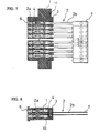
- Referring first to Figures 1 through 8, a receptacle-type electrical connector according to a first embodiment is described. As shown in Figures 1 and 2, the receptacle connector comprises an elongated
insulative housing 1, a plurality ofreceptacle terminals 2 and a corresponding plurality ofstoppers 3. - The
housing 1 is composed of an upper and a lower row of terminal-receivingcavities 4. Theterminals 2a are inserted in the upper and lower terminal-receivingcavities 4 of thehousing 1 and are adapted to be connected to electronic circuitry (not shown) formed on opposite surfaces of acircuit board 5 of an IC card, thereby permitting the circuitry of the circuit board to be connected to mating contact pins (not shown) when the contact pins are received throughinlet apertures 6 ofhousing 1. The receptacle connector is adapted to be fixed to one end of the circuit board, as shown in Figure 2. - As best seen in Figure 2, the terminal-receiving
cavities 4 are sealed at their ends bystoppers 3, thereby preventing the ingress of foreign substances into the IC card through the inlet apertures and the terminal-receiving cavities, and preventing contamination of the internal circuitry of the circuit board. - Looking now to Figures 3 and 4, the terminals are shown prior to assembly of the receptacle connector. The
terminals 2 are arranged at a given spacing and connected by acarrier strip 7. Each terminal includes aterminal contact 2a at an end opposite the carrier strip, and aconductor extension 2b which extends between theterminal contact 2a and thecarrier strip 7.Guide pieces 8 are arranged betweenadjacent conductor extensions 2b, and also extend fromcarrier strip 7. - During assembly of the receptacle connector,
guide pieces 8 are cut and removed fromcarrier strip 7, and theterminal contacts 2a are arranged at predetermined spacing, for example at intervals of 1.0 mm. The terminals are then insert-molded with the stoppers to form a unitary terminal-and-stopper assembly. - The terminal-and-stopper assembly is then press-fit into
housing 1 from the rear end thereof by insertingterminal contacts 2a into terminal-receivingcavities 4 so that the stoppers are press-fit within a recess or opening 11 ofhousing 1, as shown in Figures 5 and 6. The fully assembled receptacle is shown in Figures 7 and 8. - As seen from these drawings, and in particular Figure 8, the
cavities 4 ofhousing 1 are completely sealed by thestopper 3, which otherwise would permit foreign contaminants into the IC card by way of the terminal-receiving cavities and expose the circuitry of the printed circuit board thereto. - After press-fitting the terminal-and-stopper assembly into the housing, the
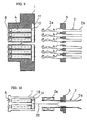
carrier strip 7 is then cut and removed from theconductive extensions 2b, and then, as shown in Figure 2, the free ends of theconductive extensions 2b are formed divergently to facilitate the insertion of thecircuit board 5 between the rows ofterminals 2 and the soldering of the free ends of theextensions 2b to the surface of the circuit board. - Referring now to Figures 9 through 12, a receptacle connector is described according to a second embodiment of the invention. In the first embodiment,
terminals 2 andassociated stoppers 3 are insert-molded to form a single terminal-and-stopper assembly. In the second embodiment, theterminals 2 are simply press-fit within an associatedstopper member 3 to provide the unitary terminal-and-stopper assembly. - As in the first embodiment, the terminal-and-stopper assembly is then press-fit into
housing 1 from the rear end thereof, as indicated byarrow 20 in Figure 10, untilstopper 3 is positively fixed or press-fit intorecess 11 ofhousing 1, to provide the receptacle assembly as shown in Figures 11 and 12. - Next, and now referring to Figures 13 and 14, a receptacle connector is described according to a third embodiment of the invention. In the first and second embodiments, the receptacle connector is adapted to be fixed to the end of the circuit board 5 (Fig. 2), but in the third embodiment the receptacle is fixed to the surface of a circuit board 5 (Fig. 14(c)).
- As shown in Figure 13,
terminals 2 and associatedstopper 3 are integrally connected by either method described above, and then, as shown in Figures 14a and 14b, the terminal-and-stopper assembly is assembled withinhousing 1. - The receptacle is then adapted to be fixed to the surface of the
circuit board 5 of an IC card as shown in Figure 14c. Mating contact pins are adapted to be inserted into the receptacle in a direction transverse to the surface ofcircuit board 5. - As understood from the above, a receptacle connector according to the present invention includes a housing whose terminal-receiving cavities are each sealed by a stopper to prevent the ingress of foreign particles therethrough and to avoid the potential contamination of and/or damage to the circuitry of the internal circuit board of an IC card in which the receptacle connector is assembled.
Claims (7)
- A receptacle connector for an IC card comprising:an elongated housing (1) having a plurality of terminal-receiving cavities (4) extending therethrough, and a plurality of inlet openings (6) formed at a first end of the housing and communicating with the terminal-receiving cavities for receiving contact pins of a mating connector,a plurality of terminals (2) within the terminal-receiving cavities (4) for electrically connecting to the contact pins of the mating connector,a plurality of stoppers (3) each attached to a corresponding one of the plurality of terminals (2) wherein each stopper is press-fit within the housing at a second end thereof, whereby each terminal-receiving cavity is sealed by one of the stoppers to prevent the ingress of foreign particles therethrough.
- A receptacle connector as set forth in claim 1 wherein the terminal-receiving cavities of the elongated housing and the terminals therein are arranged in two rows.
- A receptacle connector as set forth in claim 1 wherein the plurality of stoppers are formed in a unitary member which fits within a recess (11) in the elongated housing.
- A receptacle connector as set forth in claim 1 wherein the terminals are press-fit into the stoppers to form a single terminal-and-stopper assembly and the stoppers retain the terminals in their proper position within the housing.
- A receptacle connector as set forth in claim 2 wherein the two rows of terminals are defined by an upper row of terminals and a lower row of terminals which are adapted to straddle a printed circuit board (5) of the IC card.
- A receptacle connector as set forth in claim 1 wherein each terminal includes a terminal contact (2a) at one end thereof and a conductor extension (26) which extends from the terminal contact, wherein the respective stopper is located along the conductor extension (26) proximate the joint between the terminal contact and the conductor extension.
- A method of fabricating a receptacle connector for an IC card, the receptacle connector including an elongated housing (1) having a plurality of terminal-receiving cavities (4) extending therethrough, a plurality of terminals (2) in the form of a terminal strip and adapted for positioning within the terminal-receiving cavities (4), and a plurality of stoppers (3) each corresponding to one of the plurality of terminals and adapted to be press-fit within the housing, the method comprising the steps of:a) overmolding the strip of terminals to the stoppers to provide a unitary terminal-and-stopper assembly;b) inserting the terminal-and-stopper assembly into the housing so that each of the plurality of terminals is positioned within a corresponding terminal-receiving cavity; andc) fixing the stoppers within a recess in the housing wherein the terminals are properly positioned within the housing to receive the mating pins of a mating connector and wherein the terminal-receiving cavities are each sealed at one end by a corresponding stopper to prevent the ingress of foreign substances therethrough.
Applications Claiming Priority (2)
| Application Number | Priority Date | Filing Date | Title |
|---|---|---|---|
| JP200200/94 | 1994-08-02 | ||
| JP6200200A JPH0864315A (en) | 1994-08-02 | 1994-08-02 | Receptacle type electricity connector |
Publications (2)
| Publication Number | Publication Date |
|---|---|
| EP0696086A1 EP0696086A1 (en) | 1996-02-07 |
| EP0696086B1 true EP0696086B1 (en) | 1997-09-10 |
Family
ID=16420471
Family Applications (1)
| Application Number | Title | Priority Date | Filing Date |
|---|---|---|---|
| EP95111591A Expired - Lifetime EP0696086B1 (en) | 1994-08-02 | 1995-07-24 | Sealed receptacle connector for PC card |
Country Status (6)
| Country | Link |
|---|---|
| US (1) | US5597324A (en) |
| EP (1) | EP0696086B1 (en) |
| JP (1) | JPH0864315A (en) |
| KR (1) | KR200146617Y1 (en) |
| CN (1) | CN1120748A (en) |
| DE (1) | DE69500689T2 (en) |
Families Citing this family (17)
| Publication number | Priority date | Publication date | Assignee | Title |
|---|---|---|---|---|
| AU708668B2 (en) * | 1997-11-21 | 1999-08-12 | Xybernaut Corporation | A computer structure for accommodating a PC card |
| US6000975A (en) * | 1997-12-12 | 1999-12-14 | 3M Innovative Properties Company | Canted beam electrical contact and receptacle housing therefor |
| US6453552B1 (en) * | 1998-01-30 | 2002-09-24 | Molex Incorporated | Method of manufacturing electrical terminals and terminal modules |
| US6152781A (en) * | 1999-08-12 | 2000-11-28 | Hon Hai Precisdion Ind. Co., Ltd. | Electrical connector |
| US6409541B1 (en) * | 2000-11-02 | 2002-06-25 | Autonetworks Technologies, Ltd. | Waterproof structure in cable insertion section, method of manufacturing the same, and die for waterproof molding |
| US6402552B1 (en) | 2001-08-07 | 2002-06-11 | Fci Americas Technology, Inc. | Electrical connector with overmolded and snap locked pieces |
| JP2005019321A (en) * | 2003-06-27 | 2005-01-20 | Auto Network Gijutsu Kenkyusho:Kk | Connector and manufacturing method of connector |
| US8033868B2 (en) * | 2008-08-27 | 2011-10-11 | Hon Hai Precision Ind. Co., Ltd. | Electrical connector with a tongue |
| DE102011051644B4 (en) * | 2011-07-07 | 2014-11-13 | Amphenol-Tuchel Electronics Gmbh | Interface connector |
| JP5391308B2 (en) * | 2012-05-17 | 2014-01-15 | 日本航空電子工業株式会社 | Waterproof connector |
| JP6005448B2 (en) * | 2012-09-04 | 2016-10-12 | 日本航空電子工業株式会社 | Waterproof connector |
| CN105794048B (en) * | 2013-10-03 | 2018-07-31 | 莫列斯有限公司 | Electrical connection with sealing structure |
| CN104795657B (en) * | 2014-01-16 | 2017-07-11 | 凡甲电子(苏州)有限公司 | Rechargeable battery socket |
| DE102014223644A1 (en) * | 2014-11-19 | 2016-05-19 | Zf Friedrichshafen Ag | Plug arrangement with at least one plug element |
| JP6534370B2 (en) * | 2016-08-29 | 2019-06-26 | 矢崎総業株式会社 | Pin terminal and connector |
| US9877404B1 (en) * | 2017-01-27 | 2018-01-23 | Ironwood Electronics, Inc. | Adapter apparatus with socket contacts held in openings by holding structures |
| DE102021105218A1 (en) | 2021-03-04 | 2022-09-08 | Marquardt Gmbh | Switch module designed with a sealed interface |
Family Cites Families (10)
| Publication number | Priority date | Publication date | Assignee | Title |
|---|---|---|---|---|
| JPS5322748Y2 (en) * | 1972-04-13 | 1978-06-13 | ||
| US4808115A (en) * | 1987-07-28 | 1989-02-28 | Amp Incorporated | Line replaceable connector assembly for use with printed circuit boards |
| EP0301721B1 (en) * | 1987-07-28 | 1993-10-06 | The Whitaker Corporation | Line replaceable connector assembly for use with printed circuit boards |
| US4776813A (en) * | 1987-12-08 | 1988-10-11 | Molex Incorporated | Sealed connector assembly |
| FR2641135A1 (en) * | 1988-12-23 | 1990-06-29 | Thomson Csf | Method of manufacturing a sealed connector and connector obtained by this method |
| JPH02204980A (en) * | 1989-01-25 | 1990-08-14 | Thomas & Betts Corp <T&B> | Connector |
| US4981446A (en) * | 1989-11-06 | 1991-01-01 | The Boeing Company | Modular, circular, environment resistant electrical connector assembly |
| US5145410A (en) * | 1990-08-06 | 1992-09-08 | Yazaki Corporation | Waterproof connector |
| JP2505387Y2 (en) * | 1991-02-12 | 1996-07-31 | 矢崎総業株式会社 | Fixed structure of terminal fittings and waterproof plugs |
| US5266045A (en) * | 1991-10-28 | 1993-11-30 | Yazaki Corporation | Waterproof connector |
-
1994
- 1994-08-02 JP JP6200200A patent/JPH0864315A/en active Pending
-
1995
- 1995-06-30 US US08/497,011 patent/US5597324A/en not_active Expired - Fee Related
- 1995-07-24 DE DE69500689T patent/DE69500689T2/en not_active Expired - Fee Related
- 1995-07-24 EP EP95111591A patent/EP0696086B1/en not_active Expired - Lifetime
- 1995-08-01 KR KR2019950019879U patent/KR200146617Y1/en not_active IP Right Cessation
- 1995-08-01 CN CN95109334A patent/CN1120748A/en active Pending
Also Published As
| Publication number | Publication date |
|---|---|
| DE69500689D1 (en) | 1997-10-16 |
| JPH0864315A (en) | 1996-03-08 |
| DE69500689T2 (en) | 1998-03-12 |
| EP0696086A1 (en) | 1996-02-07 |
| CN1120748A (en) | 1996-04-17 |
| KR200146617Y1 (en) | 1999-06-15 |
| US5597324A (en) | 1997-01-28 |
| KR960009316U (en) | 1996-03-16 |
Similar Documents
| Publication | Publication Date | Title |
|---|---|---|
| EP0696086B1 (en) | Sealed receptacle connector for PC card | |
| US4274700A (en) | Low cost electrical connector | |
| US5702258A (en) | Electrical connector assembled from wafers | |
| EP0772898B1 (en) | Improved grounding shroud for electrical connectors | |
| US6071152A (en) | Electrical connector with inserted terminals | |
| US7198519B2 (en) | Edge card connector assembly with keying means for ensuring proper connection | |
| US3966290A (en) | Polarized connector | |
| US6231355B1 (en) | Matched impedance connector having retention device on a grounding plane | |
| US6592407B2 (en) | High-speed card edge connector | |
| EP0633631B1 (en) | Edge mounted circuit board electrical connector | |
| US5281165A (en) | Electrical connector shroud adapted for shorting bar removal | |
| KR100248966B1 (en) | Electrical connector with sensing terminal system | |
| US7367818B2 (en) | Onboard connector | |
| US6371790B1 (en) | Electrical assembly having anti-mismating device | |
| US20040053540A1 (en) | Electrical connector and method of assembling the same | |
| US20030166347A1 (en) | Low-profile connector for circuit boards | |
| US6508665B1 (en) | Electrical connector having printed circuit board mounted therein | |
| US7413476B2 (en) | Electrical interconnection with mating terminals | |
| US6688909B1 (en) | Stacked connector with leds | |
| US6645009B1 (en) | High density electrical connector with lead-in device | |
| US5997312A (en) | Grounding contact for high speed, high density connector | |
| EP0932226A2 (en) | Card connector | |
| US6152781A (en) | Electrical connector | |
| EP1276181B1 (en) | Electrical connector for receiving a plug | |
| CA1101953A (en) | Interconnection between printed circuit board panels and external components |
Legal Events
| Date | Code | Title | Description |
|---|---|---|---|
| PUAI | Public reference made under article 153(3) epc to a published international application that has entered the european phase |
Free format text: ORIGINAL CODE: 0009012 |
|
| AK | Designated contracting states |
Kind code of ref document: A1 Designated state(s): DE FR GB IT NL |
|
| 17P | Request for examination filed |
Effective date: 19960724 |
|
| GRAG | Despatch of communication of intention to grant |
Free format text: ORIGINAL CODE: EPIDOS AGRA |
|
| 17Q | First examination report despatched |
Effective date: 19961217 |
|
| GRAH | Despatch of communication of intention to grant a patent |
Free format text: ORIGINAL CODE: EPIDOS IGRA |
|
| ITF | It: translation for a ep patent filed |
Owner name: 0508;08MIFDE DOMINICIS & MAYER S.R.L. |
|
| GRAH | Despatch of communication of intention to grant a patent |
Free format text: ORIGINAL CODE: EPIDOS IGRA |
|
| GRAA | (expected) grant |
Free format text: ORIGINAL CODE: 0009210 |
|
| AK | Designated contracting states |
Kind code of ref document: B1 Designated state(s): DE FR GB IT NL |
|
| REF | Corresponds to: |
Ref document number: 69500689 Country of ref document: DE Date of ref document: 19971016 |
|
| ET | Fr: translation filed | ||
| PLBE | No opposition filed within time limit |
Free format text: ORIGINAL CODE: 0009261 |
|
| STAA | Information on the status of an ep patent application or granted ep patent |
Free format text: STATUS: NO OPPOSITION FILED WITHIN TIME LIMIT |
|
| 26N | No opposition filed | ||
| PGFP | Annual fee paid to national office [announced via postgrant information from national office to epo] |
Ref country code: GB Payment date: 20000614 Year of fee payment: 6 |
|
| PGFP | Annual fee paid to national office [announced via postgrant information from national office to epo] |
Ref country code: NL Payment date: 20000620 Year of fee payment: 6 |
|
| PGFP | Annual fee paid to national office [announced via postgrant information from national office to epo] |
Ref country code: FR Payment date: 20000707 Year of fee payment: 6 |
|
| PGFP | Annual fee paid to national office [announced via postgrant information from national office to epo] |
Ref country code: DE Payment date: 20000727 Year of fee payment: 6 |
|
| PG25 | Lapsed in a contracting state [announced via postgrant information from national office to epo] |
Ref country code: GB Free format text: LAPSE BECAUSE OF NON-PAYMENT OF DUE FEES Effective date: 20010724 |
|
| PG25 | Lapsed in a contracting state [announced via postgrant information from national office to epo] |
Ref country code: NL Free format text: LAPSE BECAUSE OF NON-PAYMENT OF DUE FEES Effective date: 20020201 |
|
| GBPC | Gb: european patent ceased through non-payment of renewal fee |
Effective date: 20010724 |
|
| PG25 | Lapsed in a contracting state [announced via postgrant information from national office to epo] |
Ref country code: FR Free format text: LAPSE BECAUSE OF NON-PAYMENT OF DUE FEES Effective date: 20020329 |
|
| NLV4 | Nl: lapsed or anulled due to non-payment of the annual fee |
Effective date: 20020201 |
|
| PG25 | Lapsed in a contracting state [announced via postgrant information from national office to epo] |
Ref country code: DE Free format text: LAPSE BECAUSE OF NON-PAYMENT OF DUE FEES Effective date: 20020501 |
|
| REG | Reference to a national code |
Ref country code: FR Ref legal event code: ST |
|
| PG25 | Lapsed in a contracting state [announced via postgrant information from national office to epo] |
Ref country code: IT Free format text: LAPSE BECAUSE OF NON-PAYMENT OF DUE FEES;WARNING: LAPSES OF ITALIAN PATENTS WITH EFFECTIVE DATE BEFORE 2007 MAY HAVE OCCURRED AT ANY TIME BEFORE 2007. THE CORRECT EFFECTIVE DATE MAY BE DIFFERENT FROM THE ONE RECORDED. Effective date: 20050724 |