EP0695942A2 - Large capacity magazine with interchangeable container - Google Patents
Large capacity magazine with interchangeable container Download PDFInfo
- Publication number
- EP0695942A2 EP0695942A2 EP95250171A EP95250171A EP0695942A2 EP 0695942 A2 EP0695942 A2 EP 0695942A2 EP 95250171 A EP95250171 A EP 95250171A EP 95250171 A EP95250171 A EP 95250171A EP 0695942 A2 EP0695942 A2 EP 0695942A2
- Authority
- EP
- European Patent Office
- Prior art keywords
- probes
- interchangeable container
- cams
- base frame
- magazine
- Prior art date
- Legal status (The legal status is an assumption and is not a legal conclusion. Google has not performed a legal analysis and makes no representation as to the accuracy of the status listed.)
- Granted
Links
Images


Classifications
-
- B—PERFORMING OPERATIONS; TRANSPORTING
- B01—PHYSICAL OR CHEMICAL PROCESSES OR APPARATUS IN GENERAL
- B01L—CHEMICAL OR PHYSICAL LABORATORY APPARATUS FOR GENERAL USE
- B01L9/00—Supporting devices; Holding devices
-
- G—PHYSICS
- G01—MEASURING; TESTING
- G01N—INVESTIGATING OR ANALYSING MATERIALS BY DETERMINING THEIR CHEMICAL OR PHYSICAL PROPERTIES
- G01N1/00—Sampling; Preparing specimens for investigation
- G01N1/02—Devices for withdrawing samples
- G01N1/10—Devices for withdrawing samples in the liquid or fluent state
- G01N1/12—Dippers; Dredgers
- G01N1/125—Dippers; Dredgers adapted for sampling molten metals
-
- G—PHYSICS
- G01—MEASURING; TESTING
- G01N—INVESTIGATING OR ANALYSING MATERIALS BY DETERMINING THEIR CHEMICAL OR PHYSICAL PROPERTIES
- G01N35/00—Automatic analysis not limited to methods or materials provided for in any single one of groups G01N1/00 - G01N33/00; Handling materials therefor
- G01N35/02—Automatic analysis not limited to methods or materials provided for in any single one of groups G01N1/00 - G01N33/00; Handling materials therefor using a plurality of sample containers moved by a conveyor system past one or more treatment or analysis stations
- G01N35/04—Details of the conveyor system
- G01N2035/046—General conveyor features
- G01N2035/0465—Loading or unloading the conveyor
Definitions
- the invention relates to a device for the provision of measuring and / or sampling probes for the measurement of data from molten metals, consisting of a device for storing and dispensing measuring and / or sampling probes in or from a large-capacity magazine, with a Device for removing and feeding the probes to the lance head of a sublance cooperates.
- Such probes are used, in particular, to measure data from molten metals in the converter by means of sublances, a sampling probe for the respective measurement being attachable to the end of the sublance immersed in the molten metal.
- the invention is therefore based on the object of developing a system with which this personnel and cost expenditure can be reduced and the absorption capacity of the system can be increased while at the same time increasing the functionality.
- the large-capacity magazine is designed in such a way that it consists of a stationary base frame with at least one cam wheel for separating the probes, an interchangeable container, provided with a storage space and optionally also with shafts, filled with probes of different types, being used in the base frame becomes.
- the invention offers the advantage that a large number of probes can be provided in an interchangeable container, so that constant refilling of the container is no longer necessary; rather, only the entire container is replaced if necessary.
- the latter In order to separate the probes that are located in the storage space, the latter has a narrowing area that opens into a single channel at its end, which then only allows one probe to pass through.
- the invention offers the advantage of providing different types of probes in the desired quantity depending on the metallurgical process carried out in the swap container.
- the filling of the interchangeable container with probes can advantageously be carried out at a central location, and the interchangeable containers are then transported from this central location to the base frame by means of suitable transport means and connected to it.
- brackets are provided which correspond to the shape of the cams. They are stationary in the narrowed area of the swap body where the cams of the cam wheel protrude when inserted. By means of these brackets it can be excluded that a probe is arranged in this area when the interchangeable container is being filled. Thus, the process of inserting the swap body into the base frame provided with cams can run smoothly.
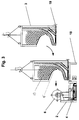
- FIGS. 1 and 2 show a large-capacity magazine 1 with an interchangeable container 3 filled with probes, inserted into a stationary base frame 2.
- the interchangeable container 3 is provided with a corresponding storage space 13 for receiving first probes 11.
- the storage room 13 merges into a single channel 13a via a constriction area 15.
- the individual channel 13a opens at 13b into a shaped piece 10 which is rotatably mounted in the base frame 2.
- the probes 11 are separated via the rotating molding 10 and placed on the discharge device 4 of the base frame.
- the discharge device 4 consists of a conveyor belt 4a, which is moved by means of transport shafts 9 and a piston-cylinder unit 8.
- the probes fall onto the conveyor belt, are positioned and then transported to the erection arm 17, which allows the connection to the respective sublance held and aligned in a system (not shown).
- the cams 16 of one or more cam wheels 6 protrude into the constriction area 15 of the interchangeable container 3.
- a drive 5 rotates the cam wheels 6 by means of a drive shaft 7 in the opposite direction to the downward force of the probes in the storage space. This rotary movement causes uniform insertion of individual probes into the guide channel 13a and counteracts a possible jamming of the probes in the constriction 15.
- FIG. 2 also shows a partial area representation of the storage space 13 in the narrowing area 15.
- the cams 6 of the cam wheel 16 extend when the interchangeable container 3 and base frame 2 are joined, there are stationary brackets 20 on Exchangeable containers are provided, which rule out that a probe becomes lodged in this area when the storage space is filled, which would make it more difficult to insert the cams into the narrowing area 15 of the storage space 13.
- the device according to the invention can be adapted to the particular process for which measurement data are to be recorded.
- FIG. 3 shows the insertion of an interchangeable container 3 into the stationary base frame 2 of the large-capacity magazine 1.
- guideways 18 are provided, which again after the end of the application process can be removed.
- the placement or insertion of the swap body 3 on or in the base frame 2 can be done in an advantageous manner by means of load lifting devices and / or industrial trucks.
- Figure 3 shows a possibility of transporting the swap body 2 by means of a known load lifting device. In order to prevent probes 11, 12 from falling out during transport, for example due to fluctuations, provision is made to secure the probes by means of transport locks 19.
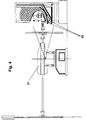
- FIG. 4 shows the use of a second embodiment of the device according to the invention in combination with sublance robots 21.
- the individual channels 13a and 14a are adapted at their mouths 22 accordingly for the pickup of the probes by the robot.
Abstract
Description
Die Erfindung betrifft eine Einrichtung für die Bereitstellung von Meß- und/oder Probenahmesonden für die Messung von Daten von Metallschmelzen, bestehend aus einer Vorrichtung zum Bevorraten und Ausgeben von Meß- und/oder Probenahmesonden in bzw. aus einem Großraum-Magazin, die mit einer Vorrichtung zur Entnahme und Zuführung der Sonden zum Lanzenkopf einer Sublanze zusammenwirkt.The invention relates to a device for the provision of measuring and / or sampling probes for the measurement of data from molten metals, consisting of a device for storing and dispensing measuring and / or sampling probes in or from a large-capacity magazine, with a Device for removing and feeding the probes to the lance head of a sublance cooperates.
Derartige Sonden dienen insbesondere zur Messung von Daten von Metallschmelzen im Konverter mittels Sublanzen, wobei eine Probennahmesonde für die jeweilige Messung am in die Metallschmelze eintauchendem Ende der Sublanze befestigbar ist.Such probes are used, in particular, to measure data from molten metals in the converter by means of sublances, a sampling probe for the respective measurement being attachable to the end of the sublance immersed in the molten metal.
Bekannt ist der Einsatz von Einrichtungen zum Bevorraten von Sonden mit automatischen Vereinzelungs- und Austragseinrichtungen. Diese bekannten Systeme haben eine begrenzte Aufnahmekapazität und erfordern eine in kurzen Abständen zu wiederholende Auffüllung. Hierbei sind die jeweiligen zeitlichen Abstände zum Auffüllen der Systeme von den einzelnen Prozessen, bei denen die Sonden zur Messung von Daten zur Anwendung kommen sollen, abhängig, d.h. bei vielen Prozessen sind während des Ablaufs zahlreiche Messungen notwendig, und dementsprechend muß eine große Anzahl von Sonden für die Messungen bereitgestellt werden.The use of devices for storing probes with automatic separation and discharge devices is known. These known systems have a limited capacity and require replenishment to be repeated at short intervals. The respective time intervals for filling up the systems depend on the individual processes in which the probes are to be used for measuring data, i.e. many processes require many measurements to be made during operation, and accordingly a large number of probes must be provided for the measurements.
Die Befüllung geschieht durch vor-Ort-Personal und macht somit dieses Verfahren personal- und kostenaufwendig.The filling is done by on-site personnel and thus makes this procedure labor-intensive and costly.
Der Erfindung liegt daher die Aufgabe zugrunde, ein System zu entwickeln, mit dem dieser Personal- und Kostenaufwand verringert sowie die Aufnahmekapazität des Systems vergrößert werden kann bei gleichzeitiger Erhöhung der Funktionstüchtigkeit.The invention is therefore based on the object of developing a system with which this personnel and cost expenditure can be reduced and the absorption capacity of the system can be increased while at the same time increasing the functionality.
Diese Aufgabe wird durch die Merkmale des Anspruchs 1 gelöst. Vorteilhafte Weiterbildungen der Erfindung sind in den Unteransprüchen enthalten.This object is solved by the features of
Erfindungsgemäß ist das Großraum-Magazin derart gestaltet, daß es aus einem stationär angeordneten Grundrahmen mit mindestens einem Nockenrad zur Vereinzelung der Sonden besteht, wobei in den Grundrahmen ein Wechselcontainer, versehen mit einem Bevorratungsraum und gegebenenfalls zusätzlich mit Schächten, vorgefüllt mit Sonden unterschiedlichen Typs, eingesetzt wird.According to the invention, the large-capacity magazine is designed in such a way that it consists of a stationary base frame with at least one cam wheel for separating the probes, an interchangeable container, provided with a storage space and optionally also with shafts, filled with probes of different types, being used in the base frame becomes.
Die Erfindung bietet den Vorteil, daß eine große Anzahl von Sonden in einem Wechselcontainer bereitgestellt werden kann, so daß ein ständiges Nachfüllen des Behälters nicht mehr nötig ist, vielmehr wird bei Bedarf lediglich der ganze Container ausgetauscht.The invention offers the advantage that a large number of probes can be provided in an interchangeable container, so that constant refilling of the container is no longer necessary; rather, only the entire container is replaced if necessary.
Zur Vereinzelung der Sonden, die sich in dem Bevorratungsraum befinden, weist dieser einen sich verengenden Bereich auf, der an seinem Ende in einen Einzelkanal mündet, der dann nur noch eine Sonde durchläßt. Durch die Bewegung der Nocken, die in den Verengungsbereich des Bevorratungsraumes hineinragen, kommt es zu einem ständigen Umschichten der sich in dem Verengungsbereich befindenden Sonden und somit zu einer Relativbewegung der Sonden zueinander, was eine Vereinzelung der Sonden bewirkt sowie einer Verklemmung der Sonden entgegenwirkt.In order to separate the probes that are located in the storage space, the latter has a narrowing area that opens into a single channel at its end, which then only allows one probe to pass through. The movement of the cams, which protrude into the constriction area of the storage space, leads to a constant shifting of the probes located in the constriction area and thus to a relative movement of the probes to one another, which causes the probes to be separated and counteracts a jamming of the probes.
Wegen der großen Anzahl an Sonden, die mehrlagig übereinander in dem Bevorratungsraum angeordnet sind, kann es nämlich erfahrungsgemäß in der Verengung zu Klemmungen aufgrund der sich einstellenden Kräftepaare zwischen den Sonden kommen. Durch eine entgegengesetzt zur abwärts wirkenden Kraft der Sonden wirkende Drehung der Nocken werden Verklemmungen der Sonden verhindert, und somit wird gewährleistet, daß stetig eine Sonde von dem Bevorratungsraum in den Führungskanal gelassen wird und daß die Bereitstellung von Sonden für die Messungen nicht unterbrochen wird.Because of the large number of probes which are arranged in multiple layers one above the other in the storage space, experience has shown that pinching due to the resulting pairs of forces between the probes can occur. By rotating the cams counter to the downward force of the probes, jamming of the probes is prevented, and thus it is ensured that a probe is constantly let into the guide channel from the storage space and that the provision of probes for the measurements is not interrupted.
Weiterhin bietet die Erfindung den Vorteil, unterschiedliche Sondentypen in der jeweils gewünschten Menge in Abhängigkeit von dem jeweilig durchgeführten metallurgischen Prozeß in dem Wechselcontainer bereitzustellen. Die Auffüllung des Wechselcontainers mit Sonden kann vorteilhaft an einer zentralen Stelle durchgeführt werden, und die Wechselcontainer werden dann von dieser zentralen Stelle über geeignete Transportmittel zu dem Grundrahmen befördert und mit diesem verbunden.Furthermore, the invention offers the advantage of providing different types of probes in the desired quantity depending on the metallurgical process carried out in the swap container. The filling of the interchangeable container with probes can advantageously be carried out at a central location, and the interchangeable containers are then transported from this central location to the base frame by means of suitable transport means and connected to it.
Als vorteilhafte Weiterentwicklung der erfindungsgemäßen Vorrichtung sind Bügel vorgesehen, die der Form der Nocken entsprechen. Sie sind dort stationär im Verengungsbereich des Wechselcontainers angeordnet, wo die Nocken des Nockenrades beim Einsetzen hineinragen. Mittels dieser Bügel kann ausgeschlossen werden, daß sich beim Befüllen des Wechselcontainers eine Sonde in diesem Bereich anordnet. Somit kann der Einsatzvorgang des Wechselcontainers in den mit Nocken versehenen Grundrahmen unproblematisch ablaufen.As an advantageous further development of the device according to the invention, brackets are provided which correspond to the shape of the cams. They are stationary in the narrowed area of the swap body where the cams of the cam wheel protrude when inserted. By means of these brackets it can be excluded that a probe is arranged in this area when the interchangeable container is being filled. Thus, the process of inserting the swap body into the base frame provided with cams can run smoothly.
Weitere Vorteile und Anwendungsmöglichkeiten sind der nachfolgenden Beschreibung und den beiliegenden Zeichnungen zu entnehmen.Further advantages and possible uses can be found in the following description and the accompanying drawings.
Sie zeigen:
- Fig. 1 eine Vorderansicht des Magazins;
- Fig. 2 eine Darstellung der Schnittfläche A-A von Fig. 1;
- Fig. 3 eine Darstellung des Einsetzens des Wechselcontainers in das Magazin und
- Fig. 4 eine weitere Ausführungsform des Magazins bei Sublanzen-Robotern.
- 1 is a front view of the magazine;
- FIG. 2 shows the sectional area AA of FIG. 1;
- Fig. 3 shows the insertion of the removable container in the magazine and
- Fig. 4 shows another embodiment of the magazine in sublance robots.
Die Figuren 1 und 2 zeigen ein Großraum-Magazin 1 mit einem mit Sonden vorgefüllten Wechselcontainer 3, eingesetzt in einen stationär angeordneten Grundrahmen 2.FIGS. 1 and 2 show a large-
Der Wechselcontainer 3 ist mit einem entsprechenden Bevorratungsraum 13 für die Aufnahme von ersten Sonden 11 versehen. Der Bevorratungsraum 13 geht über einen Verengungsbereich 15 in einen Einzelkanal 13a über. Der Einzelkanal 13a mündet bei 13b in ein Formstück 10, das im Grundrahmen 2 drehbar gelagert ist. Über das rotierende Formstück 10 werden die Sonden 11 vereinzelt und auf der Austrageinrichtung 4 des Grundrahmens abgelegt.The
Die Austrageinrichtung 4 besteht aus einem Transportband 4a, das mittels Transportwellen 9 und einer Kolben-Zylindereinheit 8 bewegt wird. Die Sonden fallen auf das Transportband, werden positioniert und dann zu dem Aufrichtarm 17 transportiert, der die Verbindung mit der jeweiligen, in einer nicht dargestellten Anlage gehaltenen und ausgerichteten Sublanze erlaubt.The
In den Verengungsbereich 15 des Wechselcontainers 3 ragen die Nocken 16 eines oder mehrerer Nockenräder 6. Ein Antrieb 5 dreht die Nockenräder 6 mittels einer Antriebswelle 7 entgegengesetzt zur abwärts wirkenden Kraft der Sonden in dem Bevorratungsraum. Durch diese Drehbewegung wird ein gleichmäßiges Einführen von einzelnen Sonden in den Führungskanal 13a bewirkt sowie einem möglichen Verklemmen der Sonden in der Verengung 15 entgegengewirkt.The
Figur 2 zeigt weiterhin eine Teilbereichsdarstellung des Bevorratungsraumes 13 im Verengungsbereich 15. Dort, wo die Nocken 6 des Nockenrades 16 beim Zusammenfügen von Wechselcontainer 3 und Grundrahmen 2 hineinreichen, sind stationär Bügel 20 am Wechselcontainer vorgesehen, die ausschließen, daß sich bei der Befüllung des Bevorratungsraumes eine Sonde in diesem Bereich festsetzt, was das Einführen der Nocken in den Verengungsbereich 15 des Bevorratungsraumes 13 erschweren würde.FIG. 2 also shows a partial area representation of the
Durch das Versehen des Wechselcontainers mit einem Bevorratungsraum 13 und einem zusätzlichen Schacht 14 bzw. Schächte, die jeweils eine unterschiedliche Menge an Sonden und Sondentypen aufnehmen können, ist die erfindungsgemäße Vorrichtung an den jeweiligen Prozeß, für den Meßdaten aufgenommen werden sollen, anpaßbar.By providing the interchangeable container with a
Figur 3 stellt das Einsetzen eines Wechselcontainers 3 in den stationär angeordneten Grundrahmen 2 des Großraum-Magazins 1 dar. Um ein sicheres und genaues Positionieren und Ineinanderführen der Elemente Wechselcontainer 3 und stationärer Grundrahmen zu gewährleisten, sind Führungsbahnen 18 vorgesehen, welche nach Beendigung des Einsatzvorgangs wieder entfernt werden können. Das Aufsetzen bzw. das Einsetzen des Wechselcontainers 3 auf bzw. in den Grundrahmen 2 kann mittels Lasthebeeinrichtungen und/oder Flurförderzeugen auf vorteilhafte Weise geschehen. Figur 3 zeigt eine Möglichkeit des Transportes des Wechselcontainers 2 mittels einer bekannten Lasthebeeinrichtung. Um ein Herausfallen von Sonden 11, 12 beim Transport, beispielsweise durch Schwankungen, zu verhindern, ist vorgesehen, die Sonden durch Transportsicherungen 19 zu sichern.FIG. 3 shows the insertion of an
In Figur 4 ist der Einsatz einer zweiten Ausführungsform der erfindungsgemäßen Vorrichtung in Kombination mit Sublanzen-Robotern 21 dargestellt. Die Einzelkanäle 13a und 14a sind an ihren Mündungen 22 entsprechend für die Aufnahme der Sonden durch den Roboter angepaßt.FIG. 4 shows the use of a second embodiment of the device according to the invention in combination with
Claims (10)
daß das Großraum-Magazin (1) einen stationär angeordneten Grundrahmen (2) aufweist, in den ein Wechselcontainer (3) einsetzbar ist, der einen Bevorratungsraum (13) aufweist, der mit Sonden (11) vorgefüllt ist, und daß der Grundrahmen (2) mindestens ein Nockenrad (6) aufweist, dessen Nocken (16) bei eingesetztem Wechselcontainer in einen sich verengenden Bereich (15) des Bevorratungsraumes (13) hineinreichen und eine Vereinzelung der in den Verengungsbereich (15) gelangten Sonden ermöglichen, wobei die Sonden (11) anschließend entlang eines Einzelkanals (13a) führbar und an dessen Mündung (13b) entnehmbar sind.Device for the provision of measuring and / or sampling probes for the measurement of data from molten metals, consisting of a device for storing and dispensing measuring and / or sampling probes (11) in or from a large-capacity magazine (1), the interacts with a device for removing and feeding the probes to the lance head of a sublance, characterized in that
that the large-capacity magazine (1) has a stationary base frame (2) into which an interchangeable container (3) can be inserted, which has a storage space (13) that is pre-filled with probes (11), and that the base frame (2 ) has at least one cam wheel (6), the cams (16) of which, when an interchangeable container is inserted, extend into a narrowing area (15) of the storage space (13) and enable the probes that have entered the narrowing area (15) to be separated, the probes (11 ) can then be guided along a single channel (13a) and can be removed at its mouth (13b).
daß in dem Wechselcontainer (3) weiterhin mindestens ein Schacht (14) vorgesehen ist, der mit zweiten Sonden (12) vorgefüllt ist, wobei die Sonden an dessen Mündung (14b) entnehmbar sind.Device according to claim 1, characterized in
that in the interchangeable container (3) there is further provided at least one shaft (14) which is pre-filled with second probes (12), the probes at the mouth (14b) being removable.
daß an der Mündung der Einzelkanäle (13b, 14b) eine die Sonden aufnehmende Austrageinrichtung (4) vorgesehen ist, die aus einem Transportband (4a) zur Aufnahme der Sonden besteht, das mittels Transportwellen (9) und einer Kolben-Zylindereinheit (8) bewegbar ist.Device according to claim 1 and 2, characterized in
that at the mouth of the individual channels (13b, 14b) a discharge device (4) receiving the probes is provided, which consists of a conveyor belt (4a) for receiving the probes, which can be moved by means of transport shafts (9) and a piston-cylinder unit (8) is.
daß im Bereich der Mündungen der Einzelkanäle (13b, 14b) am Grundrahmen drehbare Formstücke (10) zur einzelnen Aufnahme von Sonden und Abgabe dieser auf das Transportband (4a) vorgesehen sind.Device according to claim 3, characterized in
that in the area of the mouths of the individual channels (13b, 14b) rotatable moldings (10) are provided on the base frame for individually receiving probes and delivering them to the conveyor belt (4a).
Bügel (20), die der Form der Nocken entsprechen, stationär im Verengungsbereich (15) des Wechselcontainers (3) dort angeordnet sind, wo die Nocken (16) des Nockenrades (6) beim Einsetzen hineinragen.Device according to claim 1, characterized in that
Brackets (20), which correspond to the shape of the cams, are arranged stationary in the constriction area (15) of the interchangeable container (3) where the cams (16) of the cam wheel (6) protrude when inserted.
der Bevorratungsraum (13) und die Schächte (14) für unterschiedliche Sondentypen und variierende Sondenmengen eines Typs auslegt sind.Device according to claim 1 and 2, characterized in that
the storage room (13) and the shafts (14) are designed for different types of probes and varying amounts of probes of one type.
dem Großraum-Magazin (1) ein Aufrichtarm (17) zugeordnet ist, mit dessen Hilfe ein Positionieren der Sonden und Verbinden mit der jeweiligen Sublanze möglich ist.Device according to claim 1 and 3, characterized in that
an upright arm (17) is assigned to the large-capacity magazine (1), with the aid of which the probes can be positioned and connected to the respective sublance.
daß das Großraum-Magazin (1) an Anlagen mit Sublanzen-Robotern (21) einsetzbar ist, wobei die Einzelkanäle (13a, 14a) entsprechend für die Aufnahme der Sonden (11, 12) durch den Roboter (21) angepaßt sind.Device according to claim 1, characterized in
that the large-capacity magazine (1) can be used on systems with sublance robots (21), the individual channels (13a, 14a) being adapted accordingly for the pickup of the probes (11, 12) by the robot (21).
daß der Wechselcontainer (2) transportabel ist und geeignet für eine externe Befüllung mit Sonden ist.Device according to one of the preceding claims, characterized in
that the interchangeable container (2) is portable and suitable for external filling with probes.
die Sonden im Wechselcontainer (2) für den Transport durch eine Transportsicherung (19) gegen Herausfallen sicherbar sind.Device according to claim 9, characterized in that
the probes in the interchangeable container (2) can be secured against falling out by a transport lock (19) for transport.
Priority Applications (1)
| Application Number | Priority Date | Filing Date | Title |
|---|---|---|---|
| BR9503507A BR9503507A (en) | 1994-08-01 | 1995-07-31 | Device for making measuring and / or sampling probes available |
Applications Claiming Priority (2)
| Application Number | Priority Date | Filing Date | Title |
|---|---|---|---|
| DE4428838A DE4428838A1 (en) | 1994-08-01 | 1994-08-01 | Large capacity magazine with swap body |
| DE4428838 | 1994-08-01 |
Publications (3)
| Publication Number | Publication Date |
|---|---|
| EP0695942A2 true EP0695942A2 (en) | 1996-02-07 |
| EP0695942A3 EP0695942A3 (en) | 1997-06-18 |
| EP0695942B1 EP0695942B1 (en) | 2003-01-02 |
Family
ID=6525696
Family Applications (1)
| Application Number | Title | Priority Date | Filing Date |
|---|---|---|---|
| EP95250171A Expired - Lifetime EP0695942B1 (en) | 1994-08-01 | 1995-07-13 | Large capacity magazine with interchangeable container |
Country Status (3)
| Country | Link |
|---|---|
| EP (1) | EP0695942B1 (en) |
| AT (1) | ATE230490T1 (en) |
| DE (2) | DE4428838A1 (en) |
Cited By (3)
| Publication number | Priority date | Publication date | Assignee | Title |
|---|---|---|---|---|
| WO2010049161A2 (en) * | 2008-10-29 | 2010-05-06 | Sms Siemag Ag | Robotized iron and steel plant |
| CN109878767A (en) * | 2019-03-21 | 2019-06-14 | 乜红磊 | A kind of novel portable drug sampling subpackage apparatus |
| BE1026825A1 (en) | 2018-12-04 | 2020-06-26 | Vesuvius Group Sa | Metallurgical installation |
Families Citing this family (1)
| Publication number | Priority date | Publication date | Assignee | Title |
|---|---|---|---|---|
| CN108438544B (en) * | 2018-06-20 | 2019-02-15 | 柳州坚瑞新材料科技有限公司 | A kind of device of the suction pipe based on nanosecond science and technology |
Family Cites Families (4)
| Publication number | Priority date | Publication date | Assignee | Title |
|---|---|---|---|---|
| GB1542125A (en) * | 1975-07-11 | 1979-03-14 | Sumitomo Metal Ind | Apparatus for the presentation and recovery of a probe to a probe holding means |
| DE2552271B2 (en) * | 1975-11-21 | 1978-09-07 | Kuenzer Gmbh Mess-, Pruef- Und Regeltechnik, 6450 Hanau | Dispenser-like storage container, suitable for rollable objects |
| DE3214898C2 (en) * | 1982-04-22 | 1985-04-04 | Mannesmann AG, 4000 Düsseldorf | Method and device for handling measuring or sampling probe tubes in metal, in particular in steel production |
| AT382969B (en) * | 1982-12-09 | 1987-05-11 | Voest Alpine Ag | MAGAZINE FOR MEASURING AND / OR SAMPLING PROBE |
-
1994
- 1994-08-01 DE DE4428838A patent/DE4428838A1/en not_active Withdrawn
-
1995
- 1995-07-13 AT AT95250171T patent/ATE230490T1/en not_active IP Right Cessation
- 1995-07-13 EP EP95250171A patent/EP0695942B1/en not_active Expired - Lifetime
- 1995-07-13 DE DE59510517T patent/DE59510517D1/en not_active Expired - Fee Related
Non-Patent Citations (1)
| Title |
|---|
| None |
Cited By (5)
| Publication number | Priority date | Publication date | Assignee | Title |
|---|---|---|---|---|
| WO2010049161A2 (en) * | 2008-10-29 | 2010-05-06 | Sms Siemag Ag | Robotized iron and steel plant |
| WO2010049161A3 (en) * | 2008-10-29 | 2010-06-24 | Sms Siemag Ag | Robotized iron and steel plant |
| BE1026825A1 (en) | 2018-12-04 | 2020-06-26 | Vesuvius Group Sa | Metallurgical installation |
| BE1026825B1 (en) * | 2018-12-04 | 2020-07-07 | Vesuvius Group Sa | Metallurgical installation |
| CN109878767A (en) * | 2019-03-21 | 2019-06-14 | 乜红磊 | A kind of novel portable drug sampling subpackage apparatus |
Also Published As
| Publication number | Publication date |
|---|---|
| DE4428838A1 (en) | 1996-02-08 |
| DE59510517D1 (en) | 2003-02-06 |
| EP0695942A3 (en) | 1997-06-18 |
| ATE230490T1 (en) | 2003-01-15 |
| EP0695942B1 (en) | 2003-01-02 |
Similar Documents
| Publication | Publication Date | Title |
|---|---|---|
| DE3324731C2 (en) | ||
| DE2921462C2 (en) | Device for filling fuel rods | |
| WO1998048384A2 (en) | Automatic machine for dispensing money | |
| DE3490478T1 (en) | Cassette for carrying sample containers of different diameters and / or lengths | |
| DE3539965A1 (en) | DEVICE FOR TESTING AND SORTING ELECTRONIC COMPONENTS | |
| EP0551613A1 (en) | Apparatus for loading a packaging container, e.g. an open carton | |
| EP0144715A1 (en) | Device for transferring components, in particular integrated chips, from an input tray to an output tray | |
| DE3046775C2 (en) | Filter housing for accommodating a plurality of filter units | |
| EP0289452A2 (en) | Device for changing tools in NC-machining centre | |
| EP0695942A2 (en) | Large capacity magazine with interchangeable container | |
| DE2309923C2 (en) | Machine for the automatic introduction of frustoconical thread tubes into containers | |
| DE69726258T2 (en) | Coin dispenser | |
| AT154027B (en) | Device for arranging sleeves, coils and. like | |
| DE3116347C2 (en) | Canister for doubling | |
| DE19634688B4 (en) | Device for processing chip cards | |
| DE102004059870B4 (en) | Method and installation for coating objects | |
| DE4135420C2 (en) | Method for filling a round magazine in a milk sample identification system and a round bottle container | |
| DE19744980A1 (en) | Loading station for bulk goods | |
| DE3219864A1 (en) | Machine for the ordered arrangement of spinning bobbins in a reusable container | |
| DE3040195A1 (en) | ALIGNMENT DEVICE FOR TAPE CASSETTES | |
| DE2065876C3 (en) | Device for handling and introducing freshly pressed graphite and colored leads into drying containers | |
| DE2319683C2 (en) | Pin insertion device for sample drums of jacquard sample devices for textile machines | |
| DE4242763A1 (en) | Device for loading and unloading in the treatment of plate-shaped objects | |
| DE4414303C2 (en) | Dispenser for disc-shaped parking tickets | |
| EP0401197B1 (en) | Device for the storage of hardware |
Legal Events
| Date | Code | Title | Description |
|---|---|---|---|
| PUAI | Public reference made under article 153(3) epc to a published international application that has entered the european phase |
Free format text: ORIGINAL CODE: 0009012 |
|
| AK | Designated contracting states |
Kind code of ref document: A2 Designated state(s): AT DE FR GB IT LU NL |
|
| PUAL | Search report despatched |
Free format text: ORIGINAL CODE: 0009013 |
|
| AK | Designated contracting states |
Kind code of ref document: A3 Designated state(s): AT DE FR GB IT LU NL |
|
| 17P | Request for examination filed |
Effective date: 19970526 |
|
| 17Q | First examination report despatched |
Effective date: 20010420 |
|
| RAP1 | Party data changed (applicant data changed or rights of an application transferred) |
Owner name: SMS DEMAG AG |
|
| GRAH | Despatch of communication of intention to grant a patent |
Free format text: ORIGINAL CODE: EPIDOS IGRA |
|
| GRAH | Despatch of communication of intention to grant a patent |
Free format text: ORIGINAL CODE: EPIDOS IGRA |
|
| GRAA | (expected) grant |
Free format text: ORIGINAL CODE: 0009210 |
|
| AK | Designated contracting states |
Kind code of ref document: B1 Designated state(s): AT DE FR GB IT LU NL |
|
| REF | Corresponds to: |
Ref document number: 230490 Country of ref document: AT Date of ref document: 20030115 Kind code of ref document: T |
|
| REG | Reference to a national code |
Ref country code: GB Ref legal event code: FG4D Free format text: 20030102:NOT ENGLISH |
|
| GBT | Gb: translation of ep patent filed (gb section 77(6)(a)/1977) |
Effective date: 20030104 |
|
| REF | Corresponds to: |
Ref document number: 59510517 Country of ref document: DE Date of ref document: 20030206 Kind code of ref document: P |
|
| ET | Fr: translation filed | ||
| PG25 | Lapsed in a contracting state [announced via postgrant information from national office to epo] |
Ref country code: LU Free format text: LAPSE BECAUSE OF NON-PAYMENT OF DUE FEES Effective date: 20030713 Ref country code: GB Free format text: LAPSE BECAUSE OF NON-PAYMENT OF DUE FEES Effective date: 20030713 Ref country code: AT Free format text: LAPSE BECAUSE OF NON-PAYMENT OF DUE FEES Effective date: 20030713 |
|
| PLBE | No opposition filed within time limit |
Free format text: ORIGINAL CODE: 0009261 |
|
| STAA | Information on the status of an ep patent application or granted ep patent |
Free format text: STATUS: NO OPPOSITION FILED WITHIN TIME LIMIT |
|
| 26N | No opposition filed |
Effective date: 20031003 |
|
| PG25 | Lapsed in a contracting state [announced via postgrant information from national office to epo] |
Ref country code: NL Free format text: LAPSE BECAUSE OF NON-PAYMENT OF DUE FEES Effective date: 20040201 |
|
| PG25 | Lapsed in a contracting state [announced via postgrant information from national office to epo] |
Ref country code: DE Free format text: LAPSE BECAUSE OF NON-PAYMENT OF DUE FEES Effective date: 20040203 |
|
| GBPC | Gb: european patent ceased through non-payment of renewal fee |
Effective date: 20030713 |
|
| PG25 | Lapsed in a contracting state [announced via postgrant information from national office to epo] |
Ref country code: FR Free format text: LAPSE BECAUSE OF NON-PAYMENT OF DUE FEES Effective date: 20040331 |
|
| NLV4 | Nl: lapsed or anulled due to non-payment of the annual fee |
Effective date: 20040201 |
|
| REG | Reference to a national code |
Ref country code: FR Ref legal event code: ST |
|
| PG25 | Lapsed in a contracting state [announced via postgrant information from national office to epo] |
Ref country code: IT Free format text: LAPSE BECAUSE OF NON-PAYMENT OF DUE FEES Effective date: 20050713 |