EP0695516A1 - Device for adjusting the position of levers and/or racks, particularly for sports shoes - Google Patents
Device for adjusting the position of levers and/or racks, particularly for sports shoes Download PDFInfo
- Publication number
- EP0695516A1 EP0695516A1 EP95110710A EP95110710A EP0695516A1 EP 0695516 A1 EP0695516 A1 EP 0695516A1 EP 95110710 A EP95110710 A EP 95110710A EP 95110710 A EP95110710 A EP 95110710A EP 0695516 A1 EP0695516 A1 EP 0695516A1
- Authority
- EP
- European Patent Office
- Prior art keywords
- plate
- stem
- base
- respect
- fastening member
- Prior art date
- Legal status (The legal status is an assumption and is not a legal conclusion. Google has not performed a legal analysis and makes no representation as to the accuracy of the status listed.)
- Withdrawn
Links
Images


Classifications
-
- A—HUMAN NECESSITIES
- A43—FOOTWEAR
- A43C—FASTENINGS OR ATTACHMENTS OF FOOTWEAR; LACES IN GENERAL
- A43C11/00—Other fastenings specially adapted for shoes
- A43C11/14—Clamp fastenings, e.g. strap fastenings; Clamp-buckle fastenings; Fastenings with toggle levers
- A43C11/1406—Fastenings with toggle levers; Equipment therefor
- A43C11/142—Fastenings with toggle levers with adjustment means provided for on the shoe, e.g. rack
Definitions
- Italian patent no. 138370 discloses a closure device comprising a lever which is pivoted, at one end, to two shoulders protruding from a base that can be rigidly coupled to one of the flaps of the shoe; said lever has, at the surface that faces the flap, a set of teeth with which a flexible ring selectively interacts, and is rigidly coupled, at the other end, to a bracket which is in turn slidingly associated at a support that is rigidly coupled to the other flap to be joined.
- the support has a C-shaped slot adapted to vary the position of the bracket and therefore of the ring with respect to the lever.
- This solution tends to solve the problem of varying the extent of the traction applied by the closure device to compensate for unavoidable anomalies in assembly or anatomical differences in the users' feet.
- Swiss patent no. 728/61 filed on January 20, 1961 discloses a closure for ski boots that comprise a fastening lever characterized in that it is fixed on an eccentric bush rotatably arranged on the pivot of the fastening lever and provided with a secondary lever, by means of which the bush can be rotated, according to the requirements, through at least 190 o , in two extreme positions.
- the eccentricity of said bush is chosen so as to vary the position of the fastening lever by approximately half of the distance between its teeth.
- Italian patent no. 197890 discloses a fastening for ski boots of the ring and lever type, in which the ring can be detachably engaged with one of a plurality of hooks that are mutually spaced by a given pitch; the characteristic of said fastening is the fact that said hooks are formed on a plate body movably guided on a base plate towards and away from said lever for movements that are equal to a fraction of the spacing of the hooks, and there are retention means for removably locking the body on the base plate.
- a principal aim of the present invention is to solve the described technical problems, eliminating the drawbacks of the prior art by providing a device that allows to easily adjust the position of levers and/or racks to achieve optimum fastening of the flaps of a sports shoe.
- an important object is to provide an adjustment device that cannot jam and does not require particular sizes or tolerances in designing its components.
- Another important object is to provide an adjustment device in which the placement of the lever and/or of the rack is stable once it has been achieved and cannot be modified by accidental impacts on said lever and/or on said rack.
- Another important object is to provide an adjustment device that is structurally simple and is quickly and easily associatable with one of the flaps of the shoe.
- Another object is to provide a device that is reliable and safe in use and has low manufacturing costs.
- a device for adjusting the position of fastening members particularly for sports shoes characterized in that it comprises a plate that can be temporarily accommodated in a complementarily shaped seat formed on the lower surface of a strap member, a stem being eccentrically associated with said plate, said stem being slideable within a slot formed on said strap member and being rigidly coupled to a fastening member.
- the reference numeral 1 designates the device for adjusting the position of a fastening member such as a lever or a rack 2, which is particularly usable for sports shoes such as ski boots, roller skates, ice skates, and motorcycling or cycling shoes.
- Said adjustment device comprises a plate 3, which has a polygonal, or preferably circular, shape in plan view and can be temporarily accommodated at a complementarily shaped seat 4 formed at the lower surface 5 of a flap or of a strap 6 of the shoe.
- a head 7 is eccentrically associated with the plate 3 and is arranged on a plane forming an acute angle with respect to the plane of arrangement of said plate 3, a counterclockwise rotation being considered positive; a stem 8 protrudes from said head, passes through said plate, and is connected, at its free end, below a lever or rack 2.
- a slit 9 is formed in the plate 3 and is adapted to allow to rotate the plate 3 by using a coin or a screwdriver.
- the stem 8 is slideable at an adapted slot 10 formed longitudinally with respect to the flap or to the strap 6 and arranged on a plane that is diametrical with respect to the plate 3 and therefore to the seat 4.
- a rotation of the plate 3 causes the stem 8 to be arranged at the end of the slot 10 that is furthest from the edge 11 of the flap or strap 6; the same rotation moves the lever or rack 2 away from the edge 11, thus allowing to achieve, by means of conventional fastening devices, a greater degree of closure for the flap or strap, thus allowing to use this position for example if the user has a thin calf requiring tighter fastening of the leg.
- the lever and/or the rack 2 also moves closer to the edge 11 of the flap or of the strap 6, allowing to achieve a looser fastening of the shoe that can therefore be used if the user has, for example, a thick calf requiring looser fastening of the leg.
- the invention has achieved the intended aim and objects, a device having been provided that allows to quickly and easily adjust the position of a lever and/or of a rack, said position, once preset, being stable in time and being immune from changes due to accidental impacts on the shoe during sports practice.
- FIGS 10-14 illustrate a device 101, according to a further aspect of the invention, for adjusting the position of fastening elements 102, such as a lever or a rack that are subjected to the traction of a traction element such as a cable 113.
- the fastening element 102 interacts with a fastening member such as a strap or a flap 103 of the shell or of the quarter of a sports shoe, not shown in the drawings.
- Said device 101 comprises a base 104 from which two wings 105a and 105b protrude laterally, a lever arm 106 being transversely articulated to said wings; as an alternative, the base 104 can have a rack 114 provided with a set of teeth for the engagement of the traction element 113.
- the base 104 has, on the opposite side with respect to the one provided with the pair of wings 105a or 105b or with the rack, a recess that forms a seat 107 for accommodating a complementarily shaped plate 108 preferably having a substantially circular plan.
- One end of a stem 109 is eccentrically associated with said plate 108, and the opposite end of said stem is associated with, and/or connected to, the strap or a flap 103 of the shell or quarter of the shoe.
- Said stem 109 passes through an adapted slot 110 formed longitudinally with respect to the base 104 and formed at the seat 107.
- the plate 108 is preferably provided with a slit 111 that allows to turn said plate 108 by using a coin or a screwdriver.
- the slit 111 is profiled as a chord on the opposite side with respect to the stem 109.
- the strap or flap 103 have two ridges 112a and 112b that are made of flexible material, protrude so that they are mutually parallel, and are arranged adjacent and laterally with respect to the base 104 or the seat 107.
- the two ridges 112a and 112b interact with the plate 108, during the rotation of said plate, by flexing; in the stable positions of figures 11 and 13, they ensure that these positions are maintained.
- the user can turn the plate 108 through 180 o by means of a coin or a screwdriver along a plane that is parallel to the plane that contains the base, overcoming the force required to flex the two ridges 112a and 112b.
- This rotation forces a longitudinal translatory motion of the base 104 and of the accompanying lever arm 106 or of the rack 114, thus adjusting the position of the fastening elements of said shoe.
- the invention has achieved the intended aim and objects, a device having been provided that allows to easily and quickly adjust the positioning of fastening elements, such as a lever arm or a rack, said positioning, once achieved, being stable in time and being unaffected by accidental impacts against the shoe during sports practice.
- Adjustment can be performed from the outside of the shoe, without having to lift a flap or a strap thereof or to perform other operations, since the plate 8 can be accessed directly by the user.
- said plate is located outside the shoe, it is possible to mount the device in any part of the shoe, for example in the shell of a boot or skate.
- the space occupied by the device, for the part inside the shoe, is very limited, so as to not affect the fit and comfort of said shoe.
- the device is structurally very simple and has very low manufacturing costs.
Abstract
A device for adjusting the position of levers and/or racks, particularly for sports shoes, including a plate (3) that can be temporarily accommodated in a complementarily shaped seat formed on the lower surface of a flap or of a strap (6) of the shoe. A stem is eccentrically associated with the plate, is slideable within a slot (10) formed on the flap or strap, and is rigidly coupled to the lever and/or rack.
Description
- Several kinds of fastenings for the flaps of sports shoes, such as for example ski boots or skates, are currently known. Italian patent no. 138370 discloses a closure device comprising a lever which is pivoted, at one end, to two shoulders protruding from a base that can be rigidly coupled to one of the flaps of the shoe; said lever has, at the surface that faces the flap, a set of teeth with which a flexible ring selectively interacts, and is rigidly coupled, at the other end, to a bracket which is in turn slidingly associated at a support that is rigidly coupled to the other flap to be joined. The support has a C-shaped slot adapted to vary the position of the bracket and therefore of the ring with respect to the lever.
- This solution tends to solve the problem of varying the extent of the traction applied by the closure device to compensate for unavoidable anomalies in assembly or anatomical differences in the users' feet.
- However, this solution also has drawbacks essentially due to the fact that the mutual interaction between the plate and the support can be altered in case of accidental impacts, especially in the condition in which a lesser elongation is imparted to the ring, because the bracket is pre-loaded and it is therefore possible to move beyond the idle point for temporary locking to the support.
- Swiss patent no. 728/61, filed on January 20, 1961 discloses a closure for ski boots that comprise a fastening lever characterized in that it is fixed on an eccentric bush rotatably arranged on the pivot of the fastening lever and provided with a secondary lever, by means of which the bush can be rotated, according to the requirements, through at least 190o, in two extreme positions. The eccentricity of said bush is chosen so as to vary the position of the fastening lever by approximately half of the distance between its teeth.
- Although this solution allows to vary the position of the lever arm with respect to a supporting bracket rigidly coupled to a flap of the shoe, it has drawbacks; due to accidental impacts, the end position of the eccentric of the bush can in fact go beyond the idle point and therefore define an unstable position which, in case of incorrect positioning on the part of the user, is detected mainly during closure, since the eccentric rotates together with the lever.
- Italian patent no. 197890 discloses a fastening for ski boots of the ring and lever type, in which the ring can be detachably engaged with one of a plurality of hooks that are mutually spaced by a given pitch; the characteristic of said fastening is the fact that said hooks are formed on a plate body movably guided on a base plate towards and away from said lever for movements that are equal to a fraction of the spacing of the hooks, and there are retention means for removably locking the body on the base plate.
- However, even this solution has drawbacks; first of all, it is constituted by a plurality of components that increase its overall cost, and the mobility and locking of the plate-like body is intrinsically complicated, requiring considerable precision in the interconnecting parts of the various components.
- There is a difficulty in operating the plate body and the possibility of jamming during this movement.
- Finally, it is noted that all of the force applied to the plate body by the tensionable ring of the lever is entrusted to adapted teeth and complementarily shaped sets of teeth that are formed respectively on the base plate and on the plate body, and this requires use of appropriately strong materials with very small tolerances to avoid breakages or accidental disengagements.
- A principal aim of the present invention is to solve the described technical problems, eliminating the drawbacks of the prior art by providing a device that allows to easily adjust the position of levers and/or racks to achieve optimum fastening of the flaps of a sports shoe.
- Within the scope of this aim, an important object is to provide an adjustment device that cannot jam and does not require particular sizes or tolerances in designing its components.
- Another important object is to provide an adjustment device in which the placement of the lever and/or of the rack is stable once it has been achieved and cannot be modified by accidental impacts on said lever and/or on said rack.
- Another important object is to provide an adjustment device that is structurally simple and is quickly and easily associatable with one of the flaps of the shoe.
- Another object is to provide a device that is reliable and safe in use and has low manufacturing costs.
- This aim, these objects, and others which will become apparent hereinafter are achieved by a device for adjusting the position of fastening members particularly for sports shoes, characterized in that it comprises a plate that can be temporarily accommodated in a complementarily shaped seat formed on the lower surface of a strap member, a stem being eccentrically associated with said plate, said stem being slideable within a slot formed on said strap member and being rigidly coupled to a fastening member.
- Further characteristics and advantages of the invention will become apparent from the following detailed description of a particular embodiment, illustrated only by way of non-limitative example in the accompanying drawings, wherein:
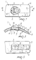
- figure 1 is a bottom view of the adjustment device, according to the invention, with the rack spaced further from the end of the flap or strap with which it is associated;
- figure 2 is a sectional view, taken along the plane II-II of figure 1;
- figure 3 is a top view of the device;
- figure 4 is a view, similar to figure 1, of the device in an intermediate position in the adjustment of the position of the rack;
- figure 5 is a sectional view, taken along the plane V-V of figure 4;
- figure 6 is a top view of the device in the position shown in figure 4;
- figure 7 is a view, similar to figure 1, of the adjustment device, arranged so as to move the rack closer to the edge of the flap or of the strap of the shoe;
- figure 8 is a sectional view, taken along the plane VIII-VIII of figure 7;
- figure 9 is a top view of the device in the position shown in figure 7;
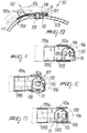
- figure 10 is a partially sectional side view of the adjustment device according to the invention, in a first stable position;
- figure 11 is a top view of the device of figure 10;
- figure 12 is a top view of the device in an unstable position, with the stem in an intermediate position of the slot;
- figure 13 is a top view of the device in a second stable position;
- figure 14 is a view, similar to figure 10, of a further embodiment of the invention.
- With reference to the above figures, the
reference numeral 1 designates the device for adjusting the position of a fastening member such as a lever or arack 2, which is particularly usable for sports shoes such as ski boots, roller skates, ice skates, and motorcycling or cycling shoes. - Said adjustment device comprises a
plate 3, which has a polygonal, or preferably circular, shape in plan view and can be temporarily accommodated at a complementarily shapedseat 4 formed at thelower surface 5 of a flap or of astrap 6 of the shoe. - A
head 7 is eccentrically associated with theplate 3 and is arranged on a plane forming an acute angle with respect to the plane of arrangement of saidplate 3, a counterclockwise rotation being considered positive; astem 8 protrudes from said head, passes through said plate, and is connected, at its free end, below a lever orrack 2. - A
slit 9 is formed in theplate 3 and is adapted to allow to rotate theplate 3 by using a coin or a screwdriver. - The
stem 8 is slideable at an adaptedslot 10 formed longitudinally with respect to the flap or to thestrap 6 and arranged on a plane that is diametrical with respect to theplate 3 and therefore to theseat 4. - As shown in figures 1 to 3, a rotation of the
plate 3 causes thestem 8 to be arranged at the end of theslot 10 that is furthest from theedge 11 of the flap orstrap 6; the same rotation moves the lever or rack 2 away from theedge 11, thus allowing to achieve, by means of conventional fastening devices, a greater degree of closure for the flap or strap, thus allowing to use this position for example if the user has a thin calf requiring tighter fastening of the leg. - As shown in figures 4 to 6, by acting at the
slit 9, the user can impart a rotation to theplate 3 through 180o, causing thestem 8 to slide at theslot 10 until the stem is arranged at the end of said slot that is closest to theedge 11 of the flap orstrap 6. - In this manner, the lever and/or the
rack 2 also moves closer to theedge 11 of the flap or of thestrap 6, allowing to achieve a looser fastening of the shoe that can therefore be used if the user has, for example, a thick calf requiring looser fastening of the leg. - It has thus been observed that the invention has achieved the intended aim and objects, a device having been provided that allows to quickly and easily adjust the position of a lever and/or of a rack, said position, once preset, being stable in time and being immune from changes due to accidental impacts on the shoe during sports practice.
- Figures 10-14 illustrate a device 101, according to a further aspect of the invention, for adjusting the position of
fastening elements 102, such as a lever or a rack that are subjected to the traction of a traction element such as acable 113. Thefastening element 102 interacts with a fastening member such as a strap or aflap 103 of the shell or of the quarter of a sports shoe, not shown in the drawings. - Said device 101 comprises a
base 104 from which twowings lever arm 106 being transversely articulated to said wings; as an alternative, thebase 104 can have arack 114 provided with a set of teeth for the engagement of thetraction element 113. - The
base 104 has, on the opposite side with respect to the one provided with the pair ofwings seat 107 for accommodating a complementarilyshaped plate 108 preferably having a substantially circular plan. - One end of a
stem 109 is eccentrically associated withsaid plate 108, and the opposite end of said stem is associated with, and/or connected to, the strap or aflap 103 of the shell or quarter of the shoe. - Said
stem 109 passes through an adaptedslot 110 formed longitudinally with respect to thebase 104 and formed at theseat 107. - The
plate 108 is preferably provided with aslit 111 that allows to turnsaid plate 108 by using a coin or a screwdriver. - Advantageously, the
slit 111 is profiled as a chord on the opposite side with respect to thestem 109. - Preferably, the strap or
flap 103 have tworidges 112a and 112b that are made of flexible material, protrude so that they are mutually parallel, and are arranged adjacent and laterally with respect to thebase 104 or theseat 107. - The two
ridges 112a and 112b interact with theplate 108, during the rotation of said plate, by flexing; in the stable positions of figures 11 and 13, they ensure that these positions are maintained. - By acting from outside, even when using the shoe, the user can turn the
plate 108 through 180o by means of a coin or a screwdriver along a plane that is parallel to the plane that contains the base, overcoming the force required to flex the tworidges 112a and 112b. - This rotation forces a longitudinal translatory motion of the
base 104 and of the accompanyinglever arm 106 or of therack 114, thus adjusting the position of the fastening elements of said shoe. - It has thus been observed that the invention has achieved the intended aim and objects, a device having been provided that allows to easily and quickly adjust the positioning of fastening elements, such as a lever arm or a rack, said positioning, once achieved, being stable in time and being unaffected by accidental impacts against the shoe during sports practice.
- Adjustment can be performed from the outside of the shoe, without having to lift a flap or a strap thereof or to perform other operations, since the
plate 8 can be accessed directly by the user. - Since said plate is located outside the shoe, it is possible to mount the device in any part of the shoe, for example in the shell of a boot or skate.
- The space occupied by the device, for the part inside the shoe, is very limited, so as to not affect the fit and comfort of said shoe.
- The device is structurally very simple and has very low manufacturing costs.
- The materials and the dimensions that constitute the individual components of the device may of course be the most pertinent according to the specific requirements.
- Where technical features mentioned in any claim are followed by reference signs, those reference signs have been included for the sole purpose of increasing the intelligibility of the claims and accordingly such reference signs do not have any limiting effect on the interpretation of each element identified by way of example by such reference signs.
Claims (11)
- Device for adjusting the position of fastening members particularly for sports shoes, characterized in that it comprises a plate (3,108) that can be temporarily accommodated in a complementarily shaped seat (4) formed on the lower surface of a strap member (6), a stem (8,109) being eccentrically associated with said plate, said stem being slideable within a slot (10) formed on said strap member and being rigidly coupled to a fastening member (2).
- Device according to claim 1, characterized in that said plate (3,108) has a circular, plan shape.
- Device according to claim 1, characterized in that said seat (4) for said plate partially affects the thickness (5) of said fastening member (2).
- Device according to claim 1, characterized in that a head (7) is eccentrically associated with said plate (3) and is arranged on a plane forming an acute angle with respect to the plane of arrangement of said plate, counterclockwise rotation being assumed as positive.
- Device according to one or more of the preceding claims, characterized in that said stem (8) protrudes from said head (7), passes through said plate, and is connected, at its free end, below a fastening member.
- Device according to one or more of the preceding claims, characterized in that a slit (9,111) is formed in said plate (3) and is adapted to allow to rotate said plate by means of a coin or other tool.
- Device according to claim 5, characterized in that said stem (8) is slidingly guided within a slot (10) formed longitudinally with respect to said fastening member.
- Device according to claim 1, characterized in that it comprises a base (104) provided with a seat (107) for accommodating said plate (108).
- Device according to one or more of the preceding claims, characterized in that said fastening member (103) has two ridges (112a, 112b) made of flexible material that protrude parallely to each other and are arranged adjacent and laterally with respect to said base (104) or seat (107).
- Device according to claim 9, characterized in that a lever arm (106) is associatable with said base (104) and is transversely pivoted to two wings (105a,105b) protruding laterally with respect to said base.
- Device according to claim 10, characterized in that a rack (114) is associatable with said base (104).
Applications Claiming Priority (4)
| Application Number | Priority Date | Filing Date | Title |
|---|---|---|---|
| ITTV940039 IT235316Y1 (en) | 1994-07-22 | 1994-07-22 | STRUCTURE OF DEVICE FOR ADJUSTING THE POSITIONING OF LEVERS AND / TIGHTENERS, ESPECIALLY FOR SPORTS FOOTWEAR. |
| ITTV940039 | 1994-07-22 | ||
| IT95TV000003A IT1279254B1 (en) | 1995-01-18 | 1995-01-18 | Structure for a device for adjusting the positioning of fastening elements, particularly for sports footwear |
| ITTV950003 | 1995-01-18 |
Publications (1)
| Publication Number | Publication Date |
|---|---|
| EP0695516A1 true EP0695516A1 (en) | 1996-02-07 |
Family
ID=26332449
Family Applications (1)
| Application Number | Title | Priority Date | Filing Date |
|---|---|---|---|
| EP95110710A Withdrawn EP0695516A1 (en) | 1994-07-22 | 1995-07-10 | Device for adjusting the position of levers and/or racks, particularly for sports shoes |
Country Status (2)
| Country | Link |
|---|---|
| EP (1) | EP0695516A1 (en) |
| JP (1) | JPH0856703A (en) |
Cited By (8)
| Publication number | Priority date | Publication date | Assignee | Title |
|---|---|---|---|---|
| EP1300092A1 (en) * | 2001-10-03 | 2003-04-09 | Lange International S.A. | Shoe with at least one fastening device |
| WO2003007746A3 (en) * | 2001-07-19 | 2003-04-17 | Tecnica Spa | Adjustable closing device for sports shoe and shoe provided with at least one device of this type |
| EP1169932A3 (en) * | 2000-07-05 | 2003-08-13 | HTM SPORT S.p.A. | Fastener particularly for sports shoes |
| FR2838926A1 (en) * | 2002-04-24 | 2003-10-31 | Salomon Sa | Tensioning device for ski-boot, comprising housing attached to disc swivel mounted to joint axle |
| EP1500342A1 (en) * | 2003-07-24 | 2005-01-26 | Lange International S.A. | Sports shoe, in particular ski-boot |
| EP1602295A1 (en) * | 2004-06-01 | 2005-12-07 | Lange International S.A. | Adjustable coupling structure of an accessory on a sport shoe |
| WO2014082891A1 (en) * | 2012-11-29 | 2014-06-05 | Gudo Ag | Clamping closure device for shoes, in particular ski or snowboard boots |
| EP3138432A1 (en) * | 2015-09-03 | 2017-03-08 | Gudo AG | Tensioning closure device for shoes, especially ski or snowboard boots |
Citations (5)
| Publication number | Priority date | Publication date | Assignee | Title |
|---|---|---|---|---|
| CH728A (en) | 1889-04-10 | 1889-06-29 | Automatic Standard Screw Compa | Machine for making screws for watches and other screws, balance rods and other similar parts |
| US3163900A (en) * | 1961-01-20 | 1965-01-05 | Martin Hans | Lacing system for footwear, particularly ski-boot fastener |
| DE7504770U (en) * | 1975-02-17 | 1975-06-12 | Lederer J | Ski boots |
| EP0300955A1 (en) * | 1987-07-21 | 1989-01-25 | Lange International S.A. | Tensioning device for a holding cable in a ski-boot |
| WO1992003071A1 (en) * | 1990-08-28 | 1992-03-05 | Koflach Sport Gesellschaft M.B.H. & Co. Kg | Buckle for shoes, in particular ski boots |
-
1995
- 1995-07-10 EP EP95110710A patent/EP0695516A1/en not_active Withdrawn
- 1995-07-14 JP JP17910995A patent/JPH0856703A/en active Pending
Patent Citations (5)
| Publication number | Priority date | Publication date | Assignee | Title |
|---|---|---|---|---|
| CH728A (en) | 1889-04-10 | 1889-06-29 | Automatic Standard Screw Compa | Machine for making screws for watches and other screws, balance rods and other similar parts |
| US3163900A (en) * | 1961-01-20 | 1965-01-05 | Martin Hans | Lacing system for footwear, particularly ski-boot fastener |
| DE7504770U (en) * | 1975-02-17 | 1975-06-12 | Lederer J | Ski boots |
| EP0300955A1 (en) * | 1987-07-21 | 1989-01-25 | Lange International S.A. | Tensioning device for a holding cable in a ski-boot |
| WO1992003071A1 (en) * | 1990-08-28 | 1992-03-05 | Koflach Sport Gesellschaft M.B.H. & Co. Kg | Buckle for shoes, in particular ski boots |
Cited By (10)
| Publication number | Priority date | Publication date | Assignee | Title |
|---|---|---|---|---|
| EP1169932A3 (en) * | 2000-07-05 | 2003-08-13 | HTM SPORT S.p.A. | Fastener particularly for sports shoes |
| WO2003007746A3 (en) * | 2001-07-19 | 2003-04-17 | Tecnica Spa | Adjustable closing device for sports shoe and shoe provided with at least one device of this type |
| EP1300092A1 (en) * | 2001-10-03 | 2003-04-09 | Lange International S.A. | Shoe with at least one fastening device |
| CH695004A5 (en) | 2001-10-03 | 2005-11-15 | Lange Int Sa | Shoe equipped with at least one closure device. |
| FR2838926A1 (en) * | 2002-04-24 | 2003-10-31 | Salomon Sa | Tensioning device for ski-boot, comprising housing attached to disc swivel mounted to joint axle |
| EP1500342A1 (en) * | 2003-07-24 | 2005-01-26 | Lange International S.A. | Sports shoe, in particular ski-boot |
| CH696998A5 (en) * | 2003-07-24 | 2008-03-14 | Lange Int Sa | Sports shoe, especially ski. |
| EP1602295A1 (en) * | 2004-06-01 | 2005-12-07 | Lange International S.A. | Adjustable coupling structure of an accessory on a sport shoe |
| WO2014082891A1 (en) * | 2012-11-29 | 2014-06-05 | Gudo Ag | Clamping closure device for shoes, in particular ski or snowboard boots |
| EP3138432A1 (en) * | 2015-09-03 | 2017-03-08 | Gudo AG | Tensioning closure device for shoes, especially ski or snowboard boots |
Also Published As
| Publication number | Publication date |
|---|---|
| JPH0856703A (en) | 1996-03-05 |
Similar Documents
| Publication | Publication Date | Title |
|---|---|---|
| US5918897A (en) | Snowboard binding | |
| US4561196A (en) | Ski boot having upper with journalled distribution plate | |
| CN1750859B (en) | Binding for keeping a boot attached to a snowboard | |
| CA1075446A (en) | Boot buckle | |
| JP3052593U (en) | Step-in snowboard binding | |
| JPH0332601A (en) | Ski boot adjustable for size | |
| US3885329A (en) | Ski boot with cantable upper | |
| US5957470A (en) | Flexible skate | |
| US3570148A (en) | Ski boot construction | |
| EP0695516A1 (en) | Device for adjusting the position of levers and/or racks, particularly for sports shoes | |
| US4882857A (en) | Closure and adjustment device, particularly for ski boots | |
| US6729642B2 (en) | Bindings for skiboots for snowboards | |
| JPH0833749A (en) | Coupling device between boots and exercise tool piece such as binding of ski, etc. | |
| US8850720B2 (en) | Sports boot | |
| US3722112A (en) | Ski boot construction | |
| EP0645102A1 (en) | Closure device, particularly for sports shoes | |
| EP0259721B1 (en) | Ski boot | |
| US5816603A (en) | Binding device for binding a shoe to a sports implement, particularly to a snowboard | |
| US4869697A (en) | Water ski binding | |
| US5386650A (en) | Ski boot with a damping device between the shell and shaft | |
| EP1044620B1 (en) | Closure device for shoes | |
| EP1136008A1 (en) | Shell, particularly for a ski boot | |
| EP0411402A2 (en) | Flexibility adjuster device, particularly for ski boots | |
| JPH04226602A (en) | Ski boot having adjustable rear-support plate | |
| JPH08224103A (en) | Ski boots |
Legal Events
| Date | Code | Title | Description |
|---|---|---|---|
| PUAI | Public reference made under article 153(3) epc to a published international application that has entered the european phase |
Free format text: ORIGINAL CODE: 0009012 |
|
| AK | Designated contracting states |
Kind code of ref document: A1 Designated state(s): AT CH DE FR IT LI |
|
| STAA | Information on the status of an ep patent application or granted ep patent |
Free format text: STATUS: THE APPLICATION HAS BEEN WITHDRAWN |
|
| 18W | Application withdrawn |
Withdrawal date: 19960821 |