EP0695433B1 - Electromotive device for exhibiting pictures - Google Patents
Electromotive device for exhibiting pictures Download PDFInfo
- Publication number
- EP0695433B1 EP0695433B1 EP94911311A EP94911311A EP0695433B1 EP 0695433 B1 EP0695433 B1 EP 0695433B1 EP 94911311 A EP94911311 A EP 94911311A EP 94911311 A EP94911311 A EP 94911311A EP 0695433 B1 EP0695433 B1 EP 0695433B1
- Authority
- EP
- European Patent Office
- Prior art keywords
- carrier
- ascending
- suspending
- housing
- rails
- Prior art date
- Legal status (The legal status is an assumption and is not a legal conclusion. Google has not performed a legal analysis and makes no representation as to the accuracy of the status listed.)
- Expired - Lifetime
Links
Images


Classifications
-
- G—PHYSICS
- G09—EDUCATION; CRYPTOGRAPHY; DISPLAY; ADVERTISING; SEALS
- G09F—DISPLAYING; ADVERTISING; SIGNS; LABELS OR NAME-PLATES; SEALS
- G09F15/00—Boards, hoardings, pillars, or like structures for notices, placards, posters, or the like
- G09F15/0087—Boards, hoardings, pillars, or like structures for notices, placards, posters, or the like including movable parts, e.g. movable by the wind
-
- G—PHYSICS
- G09—EDUCATION; CRYPTOGRAPHY; DISPLAY; ADVERTISING; SEALS
- G09F—DISPLAYING; ADVERTISING; SIGNS; LABELS OR NAME-PLATES; SEALS
- G09F11/00—Indicating arrangements for variable information in which the complete information is permanently attached to a movable support which brings it to the display position
- G09F11/30—Indicating arrangements for variable information in which the complete information is permanently attached to a movable support which brings it to the display position the display elements being fed one by one from storage place to a display position
- G09F11/32—Indicating arrangements for variable information in which the complete information is permanently attached to a movable support which brings it to the display position the display elements being fed one by one from storage place to a display position the feeding means comprising belts or chains, e.g. endless belts or chains
Definitions
- the present invention relates to an electromotive device for exhibiting pictures, and more particularly to an electromotive device, by which a large quantity of exhibits such as photographs or pictures can be kept for a long time and the exhibits can be viewed easily and conveniently.
- a photograph album is a conventional means for keeping exhibits such as photographs or pictures and viewing the exhibits on occasion.
- manual work to turn over the leaves of the album is required to view the exhibits, and it is inconvenient for a plurality of persons to view the exhibits at the same time, and further it is not easy to view the exhibits because the album is usually kept in a remote place such as a bookself.
- the automatic circulation-type picture box of Korean Utility Model Application No. 91-2357 (Applicant: Young Wun Yu who is the applicant of this application, Filing date: February 20, 1991, Publication date: September 16, 1992, Publication No. : 92-16279) shown in FIG. 1 includes an ascending carrier 45, a descending carrier 49, compressing levers 47, 411a, 412, 412a, and descending control levers 48.
- the ascending carrier 45 ascends along guiding rails 44, 44a by means of the driving force of a motor 41 by carrying up a picture keeping member, and the descending carrier 49 descends by the gravitational force to carry down a picture keeping member.
- the picture keeping members can circulate in the box, and viewers can view the changing pictures through an exhibition window formed at the front surface of the box.
- the descend carrier 49 carries the picture keeping member from the upper position to the lower position, because it falls by the gravitational force, noise is generated, and it may be unbalanced in the course of descending, so that its descending operation can not be smooth.
- support rings of the keeping members occupy a relatively large space, so that a large quantity of pictures can not be kept in the box, compared with the volume of the box.
- the automatic device for keeping and exhibiting exhibits of Korean Utility Model Application No. 91-21068 (Applicant: Young Wun Yu who is the applicant of this application, Filing date: December 2, 1991, Publication date: July 26, 1993, Publication No. : 93-12966) shown in FIG. 2 includes an ascending carrier 58' guided along guiding rails 51, 51', and a descending carrier 58 guided along guiding rails 52, 52'.
- a picture keeping member having no support ring is carried up to the upper position by the ascending carrier 58' and carried down to the lower position by the descending carrier 58, and the picture keeping members respectively at the upper position and at the lower position are compressed by serrulated supports 55, 55' and 56, 56' respectively.
- a separate complex mechanism consisting of serrulated supports 55, 55', 56, 56', cams 512, 512', rods 57, 57', and a joint 514 is required to compress the picture keeping members, and a separation of the picture keeping members can not be prevented in case that an external impact is applied in the course of compressing the keeping members, because there are not included longitudinal guiding rails in the device. Further, there is a disadvantage that the exhibits can be viewed via only one surface of the device.
- an object of the present invention to provide an electromotive device for exhibiting pictures, by which a large quantity of exhibits such as photographs or pictures can be kept well for a long time and the exhibits kept can be viewed easily and conveniently.
- the present invention relates to an electromotive device for exhibiting pictures as defined in claim 1.
- the picture keeping members respectively comprise an attachment plate on which exhibits are attached, and a suspension bar having engaging parts and suspension grooves formed at both ends thereof, and the ascending carrier and the descending carrier respectively include carrier pins at both ends thereof to be engaged with the engaging pans of the picture keeping member carried by the carriers.
- the upper compressing levers are respectively disposed at upper rear parts of the both side surfaces of the housing and respectively include two legs in the shape of a tweezer, one of which can not contact with the ascending carrier but contacts with the picture keeping member put on the ascending carrier, and to the other of which bias rotating force in the inverse direction of the picture keeping members suspended by the upper suspending rails is applied by a spring connected thereto.
- the lower compressing levers are respectively disposed near the lower suspending rails at the middle parts of both side surfaces of the housing so as to pivot about a pivot pin and respectively include two legs, one of which extends forward and upward so as to contact with the picture keeping members suspended by the lower suspending rails, the other of which extends rearward so as to contact with the ascending carrier, and to which bias rotating force in the direction of the picture keeping members suspended by the lower suspending rails is applied by a spring connected thereto.
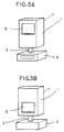
- An electromotive device for exhibiting pictures comprises an exhibit section 1, a support section 2, and a control section 3, as shown in FIGs. 3A and 3B.
- the exhibit section 1 includes a housing 11 having a front exhibition window 12 formed at the upper part of the front surface thereof and a rear exhibition window 13 formed at the lower part of the rear surface thereof.
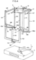
- two vertically extending front guiding rails 104 are respectively disposed at both side edges of the front surface, and two vertically extending rear guiding rails 103 are disposed at both side edges of the rear surface.
- two upper suspending rails 105 are longitudinally extended slightly declining forward
- two lower suspending rails 106 are disposed at both side edges of both side surfaces of the housing 11.
- Snap members 109 are respectively disposed at both corners between the rear guiding rails 103 and the upper suspending rails 105.
- a middle point of the snap member 109 is hingedly connected to the housing by a pivot pin 1093 so that the snap member 109 can pivot about the pivot pin 1093, and an end 1091 of the snap member 109 is connected to a spring 1094 supported by the upper suspending rails 105, the other end 1092 of the snap member 109 extends slightly inclining into the rear guiding rail 103.
- carriers 101, 102 are included in the housing 11, the ascending carrier 101 being engaged in the rear guiding rails 103, and the descending carrier 102 being engaged in the front guiding rails 104.
- the ascending carrier 101 and the descending carrier 102 respectively including carrier pins 111, 112 respectively alternate up-and-down along the rails 103, 104 by driving means.
- the driving means consists of driving motors 131, 132, driving pulleys 141, 142 connected to the respective driving motors 131, 132, following pulleys 1411, 1421, and belts 121, 122 put on the driving pulleys 141, 142 and following pulleys 1411, 1421 and respectively jointed with the ascending carrier 101 and the descending carrier 102, while in other embodiments, the carriers 101, 102 may alternate up-and-down by one driving motor, or other proper modification of the driving means can be adopted.
- Upper compressing levers 107 in the shape of tweezers are disposed at upper rear parts of the both side surfaces of the housing, and lower compressing levers 108 are disposed near the lower suspending rails at the middle pans of both side surfaces of the housing.
- the upper compressing levers 107 are disposed out of the range of the length of the ascending carrier 101, so that the empty ascending carrier 101 does not contact with the upper compressing lever 107 when it descends after carrying a picture keeping member, while the lower compressing levers 108 are disposed in the range of the length of the ascending carrier 101, so that the empty ascending carrier 101 can contact with one leg 1082 of the lower compressing lever 108 when it reaches its lower position.
- the middle parts of the respective levers 107, 108 are hingedly attached to the housing by pivot pins so that the levers 107, 108 can pivot about the respective pivot pins.
- springs 1073, 1083 are connected to the levers 107, 108 and are supported by struts 1074, 1084, thereby bias forces can be applied to the levers 107, 108.
- a picture keeping member which is carried by the carriers 101, 102 to circulate in the housing, comprises an attachment plate 154 on which exhibits are attached, and a suspension bar 151 having engaging parts 152 and suspension grooves formed at both ends thereof, as shown in FIG. 8.
- the support section 2 comprises a rotating shaft 204 for rotatively supporting the exhibit section 1, a following gear 203 incorporated with the rotating shaft 204, a driving gear 202 engaged with the following gear 203, and a rotating motor 201 connected to the driving gear 202, as shown in FIG. 4.
- a construction that a rotating motor is directly connected to a rotating shaft for rotatively supporting the exhibit section 1 can be adopted.
- FIG. 9 shows a construction of the control section 3 according to an embodiment of the present invention, which includes a power supplying circuit 301, a control signal receiving circuit 302, a carrier driving circuit 303, a rotation control circuit 304, a light control circuit 305, a timer circuit 306, a melody circuit 307, and a power switch 308.
- a user applies a driving signal to the control section 3 by means of a remote controller, power is supplied to the driving motors 131, 132 through the carrier driving circuit 303 of the control section 3, thereby the carriers 101, 102 can ascend or descend by the driving motors 131, 132.
- the picture keeping members 15 circulate in the housing 11 through the following process. That is, the engaging pans 152 of the picture keeping member 15 at the rearmost of the lower position are engaged in the carrier pins 111 of the carrier 101, and then the ascending carrier 101 with the picture keeping member 15 ascends accordingly the pulleys 141, 1411 are rotated by the driving motor 131.
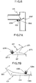
- the suspension bar 151 of the picture keeping member 15 is longer than the cater 101 so as to contact with the legs 1072 of one side of the upper compressing levers 107 in the course of ascending, thereby it can rotate the upper compressing levers 107 in the direction of the arrow in FIG. 7A by the above-mentioned contact. If the suspension bar 151 rotates the upper compressing levers 107, the legs 1071 of the other side of the upper compressing levers 107 compress the picture keeping members 15 suspended by the upper suspension rails in a forward direction.
- the upper compressing levers 107 are returned to their initial position by springs 1073. Meanwhile, the picture keeping member 15 on the carrier 101 continues to ascend to pass through the snap member 109. At this time, the suspension bar 151 of the picture keeping member 15 is put on the snap member 109 instantly by the snap action of the snap member 109 due to the spring force of the spring 1094, and then it slides down the declined snap member 109 to be put on the upper suspending rails 105, while the ascending carrier 101 descends after being emptied
- the picture keeping members 15 suspended in the upper position by the upper suspending rails 105 descend one by one by the descending carrier 102. That is, the engaging parts 152 of the suspension bar 151 of the picture keeping member 15 at the frontmost of the upper position are engaged in the carrier pins 112 of the descending carrier 102, and then the descending carrier 102 with the picture keeping member 15 descends by the driving motor 132.
- the carriers 102 When the carriers 102 reaches near its lowest position, the suspension grooves 153 of the suspension bar 151 of the picture keeping member 15 meet the lower suspending rail, and then the carrier 102 continues to descend to be disengaged with the picture keeping member 15, while the picture keeping member 15 moves rearward along the declined lower suspending rails 106.
- the descending carrier 102 after descending the picture keeping member can ascend again after being emptied, so as to descend the next picture keeping member.
- the ascending carrier 101 descends to its lowest position to press the legs 1082 of the lower compressing lever 108, so that the compressing levers 108 rotate in a direction of the arrows in FIG. 7B, and thereby the legs 1081 of the compressing levers 108 compress the picture keeping members 15 suspended by the lower suspending rails 106 rearward.
- the carrier driving circuit 303 controls the driving of the motors 131, 132 so that the operations of the ascending carrier 101 and the descending carrier 102 can be harmonized. If needed, sensors for sensing the positions of the carriers 101, 102 can be disposed at proper points of the guiding rails 103, 104 to more certainly ensure the above-mentioned control.
- Illuminating lamps to help the exhibits to be viewed well can be disposed at proper positions in the housing, and switching and lightness of the lamps 139 can be controlled by the light control circuit 305 included in the control section 3 shown in FIG. 9.
- the exhibits attached to the attachment plate 154 of the picture keeping member 15 at the upper position can be viewed through the front exhibition window 12 of the housing 11, while the exhibits attached to the attachment plate 154 of the member 15 at the lower position can be viewed through the rear exhibition window 13.
- the rotation control circuit 304 drives the rotating motor 201, which rotates the driving gear 202. And then, the following gear 203 engaged with the driving gear 202 rotates, thereby the rotating shaft incorporated with the following gear 203 and the exhibit section 1 connected thereto rotate.
- a timer circuit 306, which is included in the control section 3 as shown in FIG. 9, can switch the power switch 308.
- the electromotive device for exhibiting pictures of the present invention as described above, a large quantity of exhibits such as photographs or pictures can be kept well for a long time and the exhibits kept can be viewed easily and conveniently. And the generation of noise is reduced and the separation of the picture keeping members is prevented in operation of the device.
- the exhibits can be viewed via two opposite surfaces of the device by the viewers at two opposite positions, and viewing the exhibits without changing the viewer's position by rotating the exhibit section 1, thereby viewing the exhibits by a large number of persons at the same time is possible.
- the device presents ornamental value to the space in which the device is installed.
Abstract
Description
- The present invention relates to an electromotive device for exhibiting pictures, and more particularly to an electromotive device, by which a large quantity of exhibits such as photographs or pictures can be kept for a long time and the exhibits can be viewed easily and conveniently.
- A photograph album is a conventional means for keeping exhibits such as photographs or pictures and viewing the exhibits on occasion. However, in the conventional photo album, manual work to turn over the leaves of the album is required to view the exhibits, and it is inconvenient for a plurality of persons to view the exhibits at the same time, and further it is not easy to view the exhibits because the album is usually kept in a remote place such as a bookself.
- Meanwhile, two Korean Utility Model Applications of Serial Nos. 91-2357 and 91-21068 to overcome the above disadvantages were filed by the applicant of the present application.
- The automatic circulation-type picture box of Korean Utility Model Application No. 91-2357 (Applicant: Young Kwan Yu who is the applicant of this application, Filing date: February 20, 1991, Publication date: September 16, 1992, Publication No. : 92-16279) shown in FIG. 1 includes an
ascending carrier 45, a descendingcarrier 49,compressing levers carrier 45 ascends along guidingrails 44, 44a by means of the driving force of amotor 41 by carrying up a picture keeping member, and the descendingcarrier 49 descends by the gravitational force to carry down a picture keeping member. - Therefore, the picture keeping members can circulate in the box, and viewers can view the changing pictures through an exhibition window formed at the front surface of the box. However, when the
descend carrier 49 carries the picture keeping member from the upper position to the lower position, because it falls by the gravitational force, noise is generated, and it may be unbalanced in the course of descending, so that its descending operation can not be smooth. - Further, support rings of the keeping members occupy a relatively large space, so that a large quantity of pictures can not be kept in the box, compared with the volume of the box.
- Meanwhile, the automatic device for keeping and exhibiting exhibits of Korean Utility Model Application No. 91-21068 (Applicant: Young Kwan Yu who is the applicant of this application, Filing date: December 2, 1991, Publication date: July 26, 1993, Publication No. : 93-12966) shown in FIG. 2 includes an ascending carrier 58' guided along guiding
rails 51, 51', and a descendingcarrier 58 guided along guidingrails 52, 52'. In the device, a picture keeping member having no support ring is carried up to the upper position by the ascending carrier 58' and carried down to the lower position by the descendingcarrier 58, and the picture keeping members respectively at the upper position and at the lower position are compressed byserrulated supports serrulated supports cams 512, 512',rods 57, 57', and a joint 514 is required to compress the picture keeping members, and a separation of the picture keeping members can not be prevented in case that an external impact is applied in the course of compressing the keeping members, because there are not included longitudinal guiding rails in the device. Further, there is a disadvantage that the exhibits can be viewed via only one surface of the device. - Accordingly, it is an object of the present invention to provide an electromotive device for exhibiting pictures, by which a large quantity of exhibits such as photographs or pictures can be kept well for a long time and the exhibits kept can be viewed easily and conveniently.
- It is another object of the present invention to provide an electromotive device for exhibiting pictures, in operation of which the generation of noise is reduced and the separation of picture keeping members is prevented, and by which the exhibits can be viewed via two opposite surfaces of the device.
- It is another object of the present invention to provide an electromotive device for exhibiting pictures, by which the exhibits can be viewed by a plurality of persons at the same time and can be viewed easily and conveniently, and which presents ornamental value to the space in which the device is installed.
- The present invention relates to an electromotive device for exhibiting pictures as defined in
claim 1. - The picture keeping members respectively comprise an attachment plate on which exhibits are attached, and a suspension bar having engaging parts and suspension grooves formed at both ends thereof, and the ascending carrier and the descending carrier respectively include carrier pins at both ends thereof to be engaged with the engaging pans of the picture keeping member carried by the carriers.
- The upper compressing levers are respectively disposed at upper rear parts of the both side surfaces of the housing and respectively include two legs in the shape of a tweezer, one of which can not contact with the ascending carrier but contacts with the picture keeping member put on the ascending carrier, and to the other of which bias rotating force in the inverse direction of the picture keeping members suspended by the upper suspending rails is applied by a spring connected thereto.
- The lower compressing levers are respectively disposed near the lower suspending rails at the middle parts of both side surfaces of the housing so as to pivot about a pivot pin and respectively include two legs, one of which extends forward and upward so as to contact with the picture keeping members suspended by the lower suspending rails, the other of which extends rearward so as to contact with the ascending carrier, and to which bias rotating force in the direction of the picture keeping members suspended by the lower suspending rails is applied by a spring connected thereto.
- The above objects and other features of the present invention will become more apparent by describing the preferred embodiment thereof referring to the accompanying drawings, in which :
- FIG. 1 shows the inner construction of a conventional automatic circulation-type picture box,
- FIG. 2 shows the inner construction of another conventional automatic device for keeping and exhibiting exhibits,
- FIGs. 3A and 3B are respectively a front perspective view and a rear perspective view of an electromotive device for exhibiting pictures according to one embodiment of the present invention,
- FIG. 4 shows the inner construction of an electromotive device for exhibiting pictures according to one embodiment of the present invention,
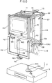
- FIG. 5 is a view to explain the circulation of picture keeping members in the device shown in FIG. 4,
- FIG. 6 is an enlarged view of a part designated by "a" in FIG. 4,
- FIGs. 7A and 7B are views to explain the disposition and the operation respectively of an upper compressing lever and a lower compressing lever of the electromotive device for exhibiting pictures shown in FIG. 4,
- FIG. 8 is a perspective view of a picture keeping member according to one embodiment of the present invention,
- FIG. 9 shows the construction of circuits included in the control section of an electromotive device for exhibiting pictures according to one embodiment of the present invention.
-
- An electromotive device for exhibiting pictures according to an embodiment of the present invention comprises an
exhibit section 1, asupport section 2, and acontrol section 3, as shown in FIGs. 3A and 3B. Theexhibit section 1 includes a housing 11 having afront exhibition window 12 formed at the upper part of the front surface thereof and arear exhibition window 13 formed at the lower part of the rear surface thereof. - In the housing 11, two vertically extending front guiding
rails 104 are respectively disposed at both side edges of the front surface, and two vertically extending rear guidingrails 103 are disposed at both side edges of the rear surface. At both side edges of the upper surface of the housing 11 are disposed two upper suspendingrails 105, which are longitudinally extended slightly declining forward, and at the middle portions of both side surfaces of the housing 11 are disposed two lower suspendingrails 106, which are longitudinally extended declining rearward.Snap members 109 are respectively disposed at both corners between the rear guidingrails 103 and the upper suspendingrails 105. Referring to FIG. 6 showing the detailed construction of thesnap member 109, a middle point of thesnap member 109 is hingedly connected to the housing by apivot pin 1093 so that thesnap member 109 can pivot about thepivot pin 1093, and anend 1091 of thesnap member 109 is connected to aspring 1094 supported by the upper suspendingrails 105, theother end 1092 of thesnap member 109 extends slightly inclining into the rear guidingrail 103. - Referring again to FIG. 4,
carriers carrier 101 being engaged in the rear guidingrails 103, and the descendingcarrier 102 being engaged in the front guidingrails 104. The ascendingcarrier 101 and the descendingcarrier 102 respectively includingcarrier pins 111, 112 respectively alternate up-and-down along therails driving motors driving pulleys respective driving motors pulleys belts driving pulleys pulleys carrier 101 and the descendingcarrier 102, while in other embodiments, thecarriers - Upper
compressing levers 107 in the shape of tweezers are disposed at upper rear parts of the both side surfaces of the housing, and lowercompressing levers 108 are disposed near the lower suspending rails at the middle pans of both side surfaces of the housing. - The upper
compressing levers 107 are disposed out of the range of the length of theascending carrier 101, so that the empty ascendingcarrier 101 does not contact with the uppercompressing lever 107 when it descends after carrying a picture keeping member, while the lowercompressing levers 108 are disposed in the range of the length of the ascendingcarrier 101, so that the empty ascendingcarrier 101 can contact with oneleg 1082 of the lowercompressing lever 108 when it reaches its lower position. The middle parts of therespective levers levers springs levers struts levers - Meanwhile, a picture keeping member, which is carried by the
carriers attachment plate 154 on which exhibits are attached, and asuspension bar 151 havingengaging parts 152 and suspension grooves formed at both ends thereof, as shown in FIG. 8. - The
support section 2 comprises arotating shaft 204 for rotatively supporting theexhibit section 1, a followinggear 203 incorporated with therotating shaft 204, adriving gear 202 engaged with the followinggear 203, and arotating motor 201 connected to thedriving gear 202, as shown in FIG. 4. However, in the other embodiments, a construction that a rotating motor is directly connected to a rotating shaft for rotatively supporting theexhibit section 1 can be adopted. - FIG. 9 shows a construction of the
control section 3 according to an embodiment of the present invention, which includes apower supplying circuit 301, a controlsignal receiving circuit 302, acarrier driving circuit 303, arotation control circuit 304, alight control circuit 305, atimer circuit 306, amelody circuit 307, and apower switch 308. - The operation of an electromotive device for exhibiting pictures according to an embodiment of the present invention having the above-described construction will be described hereinafter, referring to FIG. 5.
- If a user applies a driving signal to the
control section 3 by means of a remote controller, power is supplied to thedriving motors carrier driving circuit 303 of thecontrol section 3, thereby thecarriers driving motors - The
picture keeping members 15 circulate in the housing 11 through the following process. That is, theengaging pans 152 of thepicture keeping member 15 at the rearmost of the lower position are engaged in the carrier pins 111 of thecarrier 101, and then the ascendingcarrier 101 with thepicture keeping member 15 ascends accordingly thepulleys motor 131. - Meanwhile, the
suspension bar 151 of thepicture keeping member 15 is longer than thecater 101 so as to contact with thelegs 1072 of one side of the uppercompressing levers 107 in the course of ascending, thereby it can rotate the uppercompressing levers 107 in the direction of the arrow in FIG. 7A by the above-mentioned contact. If thesuspension bar 151 rotates the uppercompressing levers 107, thelegs 1071 of the other side of the uppercompressing levers 107 compress thepicture keeping members 15 suspended by the upper suspension rails in a forward direction. - After the
carrier 101 with thepicture keeping member 15 pass away, the uppercompressing levers 107 are returned to their initial position bysprings 1073. Meanwhile, thepicture keeping member 15 on thecarrier 101 continues to ascend to pass through thesnap member 109. At this time, thesuspension bar 151 of thepicture keeping member 15 is put on thesnap member 109 instantly by the snap action of thesnap member 109 due to the spring force of thespring 1094, and then it slides down the declinedsnap member 109 to be put on the upper suspendingrails 105, while the ascendingcarrier 101 descends after being emptied - Meanwhile, the
picture keeping members 15 suspended in the upper position by the upper suspendingrails 105 descend one by one by the descendingcarrier 102. That is, the engagingparts 152 of thesuspension bar 151 of thepicture keeping member 15 at the frontmost of the upper position are engaged in the carrier pins 112 of the descendingcarrier 102, and then the descendingcarrier 102 with thepicture keeping member 15 descends by the drivingmotor 132. - When the
carriers 102 reaches near its lowest position, thesuspension grooves 153 of thesuspension bar 151 of thepicture keeping member 15 meet the lower suspending rail, and then thecarrier 102 continues to descend to be disengaged with thepicture keeping member 15, while thepicture keeping member 15 moves rearward along the declined lower suspendingrails 106. The descendingcarrier 102 after descending the picture keeping member can ascend again after being emptied, so as to descend the next picture keeping member. Meanwhile, after thedescending carrier 102 descends thepicture keeping member 15, the ascendingcarrier 101 descends to its lowest position to press thelegs 1082 of thelower compressing lever 108, so that the compressinglevers 108 rotate in a direction of the arrows in FIG. 7B, and thereby thelegs 1081 of the compressinglevers 108 compress thepicture keeping members 15 suspended by the lower suspendingrails 106 rearward. - The operation according to the process described above can be reiterated by operating the remote controller in every case that the exhibited picture needs to be changed. Otherwise, by including a time-delay circuit in the carrier driving circuit of the
control section 3 shown in FIG. 9, it is possible to make the operations of the above process perform at every predetermined time interval such as three to four seconds or an hour corresponding to the required time to view the exhibits. - Further, it is preferred tat the lower compressing levers 108 are operated by the ascending
carrier 101 after thedescending carrier 102 descends apicture keeping member 15, and to ensure this, thecarrier driving circuit 303 controls the driving of themotors carrier 101 and the descendingcarrier 102 can be harmonized. If needed, sensors for sensing the positions of thecarriers rails - Illuminating lamps to help the exhibits to be viewed well, as shown in FIG. 9 can be disposed at proper positions in the housing, and switching and lightness of the
lamps 139 can be controlled by thelight control circuit 305 included in thecontrol section 3 shown in FIG. 9. - The exhibits attached to the
attachment plate 154 of thepicture keeping member 15 at the upper position can be viewed through thefront exhibition window 12 of the housing 11, while the exhibits attached to theattachment plate 154 of themember 15 at the lower position can be viewed through therear exhibition window 13. - However, if needed, it is also possible to view the exhibits through the
front window 12 and therear window 13 without changing the viewer's position by rotating theexhibit section 1 by means of the rotation control circuit of thecontrol section 3 shown in FIG. 9. That is, if a viewer drives therotation control circuit 304 with a remote controller, therotation control circuit 304 drives therotating motor 201, which rotates thedriving gear 202. And then, the followinggear 203 engaged with thedriving gear 202 rotates, thereby the rotating shaft incorporated with thefollowing gear 203 and theexhibit section 1 connected thereto rotate. - Furthermore, by making the
melody circuit 307 of thecontrol section 3 shown in FIG. 9 operated in rotation of theexhibit section 1, in the ascent and descent of the carriers, or in the viewer's viewing, the rotation of the exhibit section or change of the exhibits can be informed by music, or viewing with music can be possible. Atimer circuit 306, which is included in thecontrol section 3 as shown in FIG. 9, can switch thepower switch 308. - According to the electromotive device for exhibiting pictures of the present invention as described above, a large quantity of exhibits such as photographs or pictures can be kept well for a long time and the exhibits kept can be viewed easily and conveniently. And the generation of noise is reduced and the separation of the picture keeping members is prevented in operation of the device.
- Further, the exhibits can be viewed via two opposite surfaces of the device by the viewers at two opposite positions, and viewing the exhibits without changing the viewer's position by rotating the
exhibit section 1, thereby viewing the exhibits by a large number of persons at the same time is possible. Furthermore, the device presents ornamental value to the space in which the device is installed.
Claims (8)
- An electromotive device for exhibiting pictures, having an exhibit section (1) including a housing (11) having a front surface provided with a front exhibition window (12) formed at an upper part of the front surface and a rear surface opposed to said front surface,a plurality of picture keeping members (15) circulating between an upper position and a lower position in the housing (11),upper suspending means (105) for suspending the picture keeping members (15) at the upper position,lower suspending means for suspending the picture keeping members (15) at the lower position,an ascending carrier (101) for ascending the picture keeping members (15) one by one from the lower suspending means to the upper suspending means,a descending carrier (102) for descending the picture keeping members (15) one by one from the upper suspending means to the lower suspending means,first and second driving means (131, 132) which respectively provide a driving force to the ascending carrier (101) and the descending carrier (102) to ascend and descend the ascending carrier (101) and the descending carrier (102),ascending guiding means (103) and descending guiding means (104) for guiding respectively the ascending and descending of the ascending carrier (101) and the ascending and descending of the descending carrier (102),upper compressing means (107) for compressing the picture keeping members (15) suspended at the upper suspending means in an upper front direction toward said front surface of the housing (11), and lower compressing means for compressing the picture keeping members (15) suspended at the lower suspending means in a lower rear direction toward the rear surface of the housing (11),
characterized in thateach picture keeping member (15) includes an attachment plate (154) provided with exhibits on both the front and the rear surfaces thereof, a suspension bar (151) having engaging parts (152) and suspension grooves (153) formed at both ends thereof,the housing (11) is formed at a lower part of the rear surface with a rear exhibition window (13) for showing the exhibit provided on a rear surface of the attachment plate (154),the upper suspending means include two upper suspending rails (105) which is declined forward from a rear upper portion of the housing (11) to the front exhibition window (12) and extends longitudinally along both inner side edges of an upper surface of the housing (11) extending between the front and rear surfaces of the housing so that the picture keeping member (15) ascended to the upper suspending means of the housing (11) by the ascending carrier (101) is slidably moved towards the front exhibition window (12) along the upper suspending rails (105), the lower suspending means include two lower suspending rails (106) declining backward from a front lower portion of the housing (11) to the rear exhibition window (13) and extends longitudinally along middle portions of both side surfaces of the housing (11) so that the picture keeping member (15) descended to the lower position of the housing (11) by the descending carrier (102) is slidably moved towards the rear exhibition window (13) along the lower suspending rails (106) by the lower compressing means. - An electromotive device for exhibiting pictures as claimed in claim 1, characterized in that the ascending carrier (101) and the descending carrier (102) respectively include carrier pins (111, 112) at both ends thereof to be engaged with the engaging parts (152) of the picture keeping member (15) carried by the carriers (101, 102).
- An electromotive device for exhibiting pictures as claimed in claim 2, characterized in that the ascending guiding means consist of rear guiding rails (103) vertically extending at both side edges of the rear surface of the housing (11), and the descending guiding means consist of front guiding rails (104) vertically extending at both side edges of the front surface of the housing (11).
- An electromotive device for exhibiting pictures as claimed in claim 3, characterized by further comprising snap members (109) respectively disposed at both corners between the rear guiding rails (103) and the upper suspending rails (105), middle points thereof being hingedly connected by a pivot pin (1093), one end thereof being connected to springs (1094) supported by the upper suspending rails (105), the other end thereof extending as inclined into the rear guiding rails (103), so as to allow the suspension grooves (153) of the picture keeping member (15) ascended by the ascending carrier (101) to be put on the upper suspending rails (105).
- An electromotive device for exhibiting pictures as claimed in claim 4, characterized in that the upper compressing means consist of two upper compressing levers (107) respectively disposed at upper rear parts of both side surfaces of the housing (11), each upper compressing lever (107) includes two legs in shape of a tweezer, a first leg (1071) of two legs is shaped so that it can not contact with the ascending carrier (101) but can contact with the picture keeping member (15) put on the ascending carrier (101), a bias rotating force is applied to a second leg (1072) of two legs by a spring (1073) connected thereto so as to pivot the first leg toward the keeping members suspended at the upper suspending rails, the lower compressing means consist of two lower compressing levers (108) respectively disposed near the middle parts of both side surfaces of the housing (11) so as to pivot about a pivot pin, each lower compressing lever (108) includes two legs, a first leg (1081) of two legs extends forward and upward so as to contact with the picture keeping members (15) suspended at the lower suspending rails, a second leg (1082) of two legs extends rearward so as to contact with the ascending carrier (101), a bias rotating force in a direction of the picture keeping members (15) is applied to the second leg (1082) by a spring (1083) connected thereto so as to pivot the first leg toward said keeping members suspended at the lever suspending rails.
- An electromotive device for exhibiting pictures as claimed in claim 1, characterized by further comprising sensors disposed at a predetermined positions of the front guiding rails (104) and the rear guiding rails (105) to sense positions of the ascending carrier (101) and the descending carrier (102).
- An electromotive device for exhibiting pictures as claimed in claim 1, characterized by further comprising means (2) for rotatively supporting the exhibit section (1), the support means (2) including a rotating shaft (204) for rotatively supporting the exhibit section (1), a following gear (203) incorporated with the rotating shaft (204), a driving gear (202) engaged with the following gear (203), and a rotating motor (201) for driving the driving gear (202).
- An electromotive device for exhibiting pictures as claimed in claim 7, characterized by further comprising control means (3) for controlling operations of both exhibit section (1) and the support means (2), the control means (3) including:a power supply circuit (301) for supplying power to the exhibit section (1) and the support means (2); a control signal receiving circuit (302) for receiving signals from a remote controller; a carrier driving circuit (303) for driving the carriers (101, 102) to exhibit and change the pictures in the exhibit section (1); a rotation control circuit (304) for controlling a rotation of the exhibit section (1); a light control circuit (305) for controlling a lighting in the exhibit section (1); a timer circuit (306) for automatically switching a power; a melody circuit (307) for providing music in exhibiting or in changing picture; and a power switch (308).
Applications Claiming Priority (3)
| Application Number | Priority Date | Filing Date | Title |
|---|---|---|---|
| KR930005346 | 1993-04-06 | ||
| KR1993534U | 1993-04-06 | ||
| PCT/KR1994/000030 WO1994023337A1 (en) | 1993-04-06 | 1994-04-04 | Electromotive device for exhibiting pictures |
Publications (2)
| Publication Number | Publication Date |
|---|---|
| EP0695433A1 EP0695433A1 (en) | 1996-02-07 |
| EP0695433B1 true EP0695433B1 (en) | 2000-07-05 |
Family
ID=19353259
Family Applications (1)
| Application Number | Title | Priority Date | Filing Date |
|---|---|---|---|
| EP94911311A Expired - Lifetime EP0695433B1 (en) | 1993-04-06 | 1994-04-04 | Electromotive device for exhibiting pictures |
Country Status (19)
| Country | Link |
|---|---|
| US (1) | US5546686A (en) |
| EP (1) | EP0695433B1 (en) |
| JP (1) | JP2770251B2 (en) |
| KR (1) | KR960011102B1 (en) |
| CN (1) | CN1053981C (en) |
| AT (1) | ATE194428T1 (en) |
| AU (1) | AU673913B2 (en) |
| BR (1) | BR9406103A (en) |
| CA (1) | CA2159601C (en) |
| DE (1) | DE69425139T2 (en) |
| ES (1) | ES2150488T3 (en) |
| FI (1) | FI954687A (en) |
| HU (1) | HU218133B (en) |
| NO (1) | NO311115B1 (en) |
| NZ (1) | NZ263251A (en) |
| PL (1) | PL174290B1 (en) |
| TW (1) | TW253954B (en) |
| UA (1) | UA27071C2 (en) |
| WO (1) | WO1994023337A1 (en) |
Families Citing this family (9)
| Publication number | Priority date | Publication date | Assignee | Title |
|---|---|---|---|---|
| US6076084A (en) * | 1994-01-03 | 2000-06-13 | Norton-Lambert Corp. | File transfer method and apparatus utilizing delimiters |
| JPH09510559A (en) * | 1994-01-03 | 1997-10-21 | ノートン ラムバート コーポレイション | File transfer method and device using hash number |
| ES2112161B1 (en) * | 1995-05-18 | 1998-11-16 | Conei Promociones Sa | ARCHIVATOR-EXHIBITOR OF TABLES. |
| WO1999005665A1 (en) * | 1997-07-25 | 1999-02-04 | Alcea Corporation | Poster display device |
| US20070234602A1 (en) * | 2005-09-01 | 2007-10-11 | Cherng Chang | Art sheets storage, display and retrieval systems |
| KR100902648B1 (en) * | 2009-01-23 | 2009-06-15 | 박준영 | A frame with an illuminator for decoration |
| WO2010117202A2 (en) * | 2009-04-10 | 2010-10-14 | (주)엘이디웍스 | Rotatable display apparatus and a video playing method thereof |
| CN109584748A (en) * | 2018-12-27 | 2019-04-05 | 江苏莫等文化科技有限公司 | A kind of rotary advertisement exhibition device |
| CN115183090B (en) * | 2022-03-11 | 2024-02-09 | 北京兴中创国际展示有限公司 | Interactive visual transmission design and display integrated device |
Family Cites Families (10)
| Publication number | Priority date | Publication date | Assignee | Title |
|---|---|---|---|---|
| US1179490A (en) * | 1913-12-11 | 1916-04-18 | Remington Typewriter Co | Exhibiting or displaying machine. |
| US1555057A (en) * | 1922-12-07 | 1925-09-29 | Hinchey Robert Emmett | Two-story moving-display advertising machine |
| US2131168A (en) * | 1934-09-07 | 1938-09-27 | News Projection Corp | Advertising machine |
| US3813797A (en) * | 1971-09-14 | 1974-06-04 | Masters A & Sons Inc | Multiple film viewer and storage cabinet |
| US3972522A (en) * | 1975-09-02 | 1976-08-03 | Burroughs Corporation | Document view station |
| EP0035410B1 (en) * | 1980-03-05 | 1984-08-08 | Imaging Technology Limited | Reader-printer and method of producing a permanent copy therein |
| DE3014394C2 (en) * | 1980-04-15 | 1982-04-22 | Reflecta Gmbh Foto Film Projektion, 8540 Schwabach | Cassette album |
| US4928413A (en) * | 1988-06-09 | 1990-05-29 | Rapid Mounting & Finishing Company | Display device |
| JPH0267587A (en) * | 1988-09-02 | 1990-03-07 | Fujitsu Ltd | Character pattern access system |
| US5309654A (en) * | 1993-04-15 | 1994-05-10 | Mathis Johnny L | Snow and ice broom |
-
1994
- 1994-04-04 JP JP6521940A patent/JP2770251B2/en not_active Expired - Lifetime
- 1994-04-04 DE DE69425139T patent/DE69425139T2/en not_active Expired - Fee Related
- 1994-04-04 AT AT94911311T patent/ATE194428T1/en not_active IP Right Cessation
- 1994-04-04 HU HU9502908A patent/HU218133B/en not_active IP Right Cessation
- 1994-04-04 BR BR9406103A patent/BR9406103A/en not_active IP Right Cessation
- 1994-04-04 AU AU63861/94A patent/AU673913B2/en not_active Ceased
- 1994-04-04 EP EP94911311A patent/EP0695433B1/en not_active Expired - Lifetime
- 1994-04-04 US US08/343,463 patent/US5546686A/en not_active Expired - Fee Related
- 1994-04-04 UA UA95104612A patent/UA27071C2/en unknown
- 1994-04-04 KR KR1019940007058A patent/KR960011102B1/en not_active IP Right Cessation
- 1994-04-04 NZ NZ263251A patent/NZ263251A/en unknown
- 1994-04-04 CA CA002159601A patent/CA2159601C/en not_active Expired - Fee Related
- 1994-04-04 CN CN94191704A patent/CN1053981C/en not_active Expired - Fee Related
- 1994-04-04 ES ES94911311T patent/ES2150488T3/en not_active Expired - Lifetime
- 1994-04-04 PL PL94310971A patent/PL174290B1/en unknown
- 1994-04-04 WO PCT/KR1994/000030 patent/WO1994023337A1/en active IP Right Grant
- 1994-04-25 TW TW083103678A patent/TW253954B/zh active
-
1995
- 1995-10-02 FI FI954687A patent/FI954687A/en unknown
- 1995-10-05 NO NO19953969A patent/NO311115B1/en not_active IP Right Cessation
Also Published As
| Publication number | Publication date |
|---|---|
| PL174290B1 (en) | 1998-07-31 |
| ES2150488T3 (en) | 2000-12-01 |
| NO953969L (en) | 1995-12-05 |
| HUT73309A (en) | 1996-07-29 |
| EP0695433A1 (en) | 1996-02-07 |
| PL310971A1 (en) | 1996-01-22 |
| NZ263251A (en) | 1997-06-24 |
| FI954687A0 (en) | 1995-10-02 |
| UA27071C2 (en) | 2000-02-28 |
| HU9502908D0 (en) | 1995-12-28 |
| DE69425139T2 (en) | 2001-03-29 |
| KR940024648A (en) | 1994-11-18 |
| FI954687A (en) | 1995-12-01 |
| NO311115B1 (en) | 2001-10-08 |
| AU6386194A (en) | 1994-10-24 |
| AU673913B2 (en) | 1996-11-28 |
| CA2159601C (en) | 1999-06-01 |
| US5546686A (en) | 1996-08-20 |
| NO953969D0 (en) | 1995-10-05 |
| DE69425139D1 (en) | 2000-08-10 |
| ATE194428T1 (en) | 2000-07-15 |
| KR960011102B1 (en) | 1996-08-20 |
| JPH08508584A (en) | 1996-09-10 |
| CN1053981C (en) | 2000-06-28 |
| TW253954B (en) | 1995-08-11 |
| JP2770251B2 (en) | 1998-06-25 |
| HU218133B (en) | 2000-06-28 |
| WO1994023337A1 (en) | 1994-10-13 |
| CA2159601A1 (en) | 1994-10-13 |
| CN1120865A (en) | 1996-04-17 |
| BR9406103A (en) | 1995-12-19 |
Similar Documents
| Publication | Publication Date | Title |
|---|---|---|
| EP0695433B1 (en) | Electromotive device for exhibiting pictures | |
| US5575098A (en) | Illuminated display apparatus | |
| US6441828B1 (en) | Image display apparatus | |
| US20090146444A1 (en) | Configuration for Operating Interior Device and Cup Holder Using the Same | |
| DE69940675D1 (en) | Tilting seat with constant center of gravity for wheelchairs | |
| US20040259647A1 (en) | Swing | |
| US4756616A (en) | Image projection system | |
| WO2008103312A1 (en) | Edge animation multiple image display device | |
| JPH05504011A (en) | Sequential graphic material display device | |
| CN109840964A (en) | A kind of Time Attendance Device that the accuracy of identification with face identification functions is high | |
| US5440362A (en) | Transparency display system | |
| JPH09292093A (en) | Stand for home video camera | |
| RU2122228C1 (en) | Electric-powered device for displaying slides | |
| JP2005080922A (en) | Device and method for moving gift, and gift acquirement type game machine | |
| KR200242388Y1 (en) | slide type advertisement device | |
| JP2006350220A (en) | Auxiliary device for automatic photographing apparatus and automatic photographing apparatus | |
| CN216089372U (en) | Combined intelligent desk | |
| CN219828401U (en) | Photographing equipment | |
| KR920002603Y1 (en) | Zooming control apparatus of camcoder | |
| CN218626266U (en) | Shooting mechanism and self-service camera | |
| CN108294470A (en) | Camber display screen lifting gear and its panel turnover mechanism | |
| CN109035951B (en) | Media interview scene rendering system | |
| JP2000035607A (en) | Photographing auxiliary device | |
| EP1371504A1 (en) | Idea and execution of electric electronic device showing the soras of qur'an illuminated and printed on semi-transparent plastic roller | |
| US3374345A (en) | Novelty lamp construction |
Legal Events
| Date | Code | Title | Description |
|---|---|---|---|
| PUAI | Public reference made under article 153(3) epc to a published international application that has entered the european phase |
Free format text: ORIGINAL CODE: 0009012 |
|
| 17P | Request for examination filed |
Effective date: 19951106 |
|
| AK | Designated contracting states |
Kind code of ref document: A1 Designated state(s): AT BE CH DE DK ES FR GB GR IE IT LI LU MC NL PT SE |
|
| 17Q | First examination report despatched |
Effective date: 19980318 |
|
| GRAG | Despatch of communication of intention to grant |
Free format text: ORIGINAL CODE: EPIDOS AGRA |
|
| GRAG | Despatch of communication of intention to grant |
Free format text: ORIGINAL CODE: EPIDOS AGRA |
|
| GRAH | Despatch of communication of intention to grant a patent |
Free format text: ORIGINAL CODE: EPIDOS IGRA |
|
| GRAH | Despatch of communication of intention to grant a patent |
Free format text: ORIGINAL CODE: EPIDOS IGRA |
|
| GRAA | (expected) grant |
Free format text: ORIGINAL CODE: 0009210 |
|
| AK | Designated contracting states |
Kind code of ref document: B1 Designated state(s): AT BE CH DE DK ES FR GB GR IE IT LI LU MC NL PT SE |
|
| PG25 | Lapsed in a contracting state [announced via postgrant information from national office to epo] |
Ref country code: GR Free format text: LAPSE BECAUSE OF NON-PAYMENT OF DUE FEES Effective date: 20000705 Ref country code: AT Free format text: LAPSE BECAUSE OF FAILURE TO SUBMIT A TRANSLATION OF THE DESCRIPTION OR TO PAY THE FEE WITHIN THE PRESCRIBED TIME-LIMIT Effective date: 20000705 |
|
| REF | Corresponds to: |
Ref document number: 194428 Country of ref document: AT Date of ref document: 20000715 Kind code of ref document: T |
|
| REG | Reference to a national code |
Ref country code: CH Ref legal event code: EP |
|
| REG | Reference to a national code |
Ref country code: IE Ref legal event code: FG4D |
|
| REF | Corresponds to: |
Ref document number: 69425139 Country of ref document: DE Date of ref document: 20000810 |
|
| ITF | It: translation for a ep patent filed |
Owner name: STUDIO TORTA S.R.L. |
|
| REG | Reference to a national code |
Ref country code: CH Ref legal event code: NV Representative=s name: SCHMAUDER & PARTNER AG PATENTANWALTSBUERO |
|
| PG25 | Lapsed in a contracting state [announced via postgrant information from national office to epo] |
Ref country code: DK Free format text: LAPSE BECAUSE OF FAILURE TO SUBMIT A TRANSLATION OF THE DESCRIPTION OR TO PAY THE FEE WITHIN THE PRESCRIBED TIME-LIMIT Effective date: 20001005 |
|
| PG25 | Lapsed in a contracting state [announced via postgrant information from national office to epo] |
Ref country code: PT Free format text: LAPSE BECAUSE OF FAILURE TO SUBMIT A TRANSLATION OF THE DESCRIPTION OR TO PAY THE FEE WITHIN THE PRESCRIBED TIME-LIMIT Effective date: 20001006 |
|
| ET | Fr: translation filed | ||
| REG | Reference to a national code |
Ref country code: ES Ref legal event code: FG2A Ref document number: 2150488 Country of ref document: ES Kind code of ref document: T3 |
|
| PG25 | Lapsed in a contracting state [announced via postgrant information from national office to epo] |
Ref country code: LU Free format text: LAPSE BECAUSE OF NON-PAYMENT OF DUE FEES Effective date: 20010404 Ref country code: IE Free format text: LAPSE BECAUSE OF NON-PAYMENT OF DUE FEES Effective date: 20010404 |
|
| PG25 | Lapsed in a contracting state [announced via postgrant information from national office to epo] |
Ref country code: MC Free format text: LAPSE BECAUSE OF NON-PAYMENT OF DUE FEES Effective date: 20010430 |
|
| PLBE | No opposition filed within time limit |
Free format text: ORIGINAL CODE: 0009261 |
|
| STAA | Information on the status of an ep patent application or granted ep patent |
Free format text: STATUS: NO OPPOSITION FILED WITHIN TIME LIMIT |
|
| 26N | No opposition filed | ||
| REG | Reference to a national code |
Ref country code: GB Ref legal event code: IF02 |
|
| REG | Reference to a national code |
Ref country code: IE Ref legal event code: MM4A |
|
| PGFP | Annual fee paid to national office [announced via postgrant information from national office to epo] |
Ref country code: GB Payment date: 20020404 Year of fee payment: 9 |
|
| PGFP | Annual fee paid to national office [announced via postgrant information from national office to epo] |
Ref country code: ES Payment date: 20020415 Year of fee payment: 9 |
|
| PGFP | Annual fee paid to national office [announced via postgrant information from national office to epo] |
Ref country code: SE Payment date: 20020423 Year of fee payment: 9 Ref country code: FR Payment date: 20020423 Year of fee payment: 9 |
|
| PGFP | Annual fee paid to national office [announced via postgrant information from national office to epo] |
Ref country code: NL Payment date: 20020425 Year of fee payment: 9 |
|
| PGFP | Annual fee paid to national office [announced via postgrant information from national office to epo] |
Ref country code: BE Payment date: 20020429 Year of fee payment: 9 |
|
| PGFP | Annual fee paid to national office [announced via postgrant information from national office to epo] |
Ref country code: CH Payment date: 20020430 Year of fee payment: 9 |
|
| PGFP | Annual fee paid to national office [announced via postgrant information from national office to epo] |
Ref country code: DE Payment date: 20020529 Year of fee payment: 9 |
|
| PG25 | Lapsed in a contracting state [announced via postgrant information from national office to epo] |
Ref country code: GB Free format text: LAPSE BECAUSE OF NON-PAYMENT OF DUE FEES Effective date: 20030404 |
|
| PG25 | Lapsed in a contracting state [announced via postgrant information from national office to epo] |
Ref country code: SE Free format text: LAPSE BECAUSE OF NON-PAYMENT OF DUE FEES Effective date: 20030405 Ref country code: ES Free format text: LAPSE BECAUSE OF NON-PAYMENT OF DUE FEES Effective date: 20030405 |
|
| PG25 | Lapsed in a contracting state [announced via postgrant information from national office to epo] |
Ref country code: LI Free format text: LAPSE BECAUSE OF NON-PAYMENT OF DUE FEES Effective date: 20030430 Ref country code: CH Free format text: LAPSE BECAUSE OF NON-PAYMENT OF DUE FEES Effective date: 20030430 Ref country code: BE Free format text: LAPSE BECAUSE OF NON-PAYMENT OF DUE FEES Effective date: 20030430 |
|
| BERE | Be: lapsed |
Owner name: *YU YOUNG KWAN Effective date: 20030430 |
|
| PG25 | Lapsed in a contracting state [announced via postgrant information from national office to epo] |
Ref country code: NL Free format text: LAPSE BECAUSE OF NON-PAYMENT OF DUE FEES Effective date: 20031101 Ref country code: DE Free format text: LAPSE BECAUSE OF NON-PAYMENT OF DUE FEES Effective date: 20031101 |
|
| GBPC | Gb: european patent ceased through non-payment of renewal fee |
Effective date: 20030404 |
|
| NLV4 | Nl: lapsed or anulled due to non-payment of the annual fee |
Effective date: 20031101 |
|
| EUG | Se: european patent has lapsed | ||
| REG | Reference to a national code |
Ref country code: CH Ref legal event code: PL |
|
| PG25 | Lapsed in a contracting state [announced via postgrant information from national office to epo] |
Ref country code: FR Free format text: LAPSE BECAUSE OF NON-PAYMENT OF DUE FEES Effective date: 20031231 |
|
| REG | Reference to a national code |
Ref country code: FR Ref legal event code: ST |
|
| REG | Reference to a national code |
Ref country code: ES Ref legal event code: FD2A Effective date: 20030405 |
|
| PG25 | Lapsed in a contracting state [announced via postgrant information from national office to epo] |
Ref country code: IT Free format text: LAPSE BECAUSE OF NON-PAYMENT OF DUE FEES;WARNING: LAPSES OF ITALIAN PATENTS WITH EFFECTIVE DATE BEFORE 2007 MAY HAVE OCCURRED AT ANY TIME BEFORE 2007. THE CORRECT EFFECTIVE DATE MAY BE DIFFERENT FROM THE ONE RECORDED. Effective date: 20050404 |