EP0695114B1 - Static electricity eliminator - Google Patents
Static electricity eliminator Download PDFInfo
- Publication number
- EP0695114B1 EP0695114B1 EP95905233A EP95905233A EP0695114B1 EP 0695114 B1 EP0695114 B1 EP 0695114B1 EP 95905233 A EP95905233 A EP 95905233A EP 95905233 A EP95905233 A EP 95905233A EP 0695114 B1 EP0695114 B1 EP 0695114B1
- Authority
- EP
- European Patent Office
- Prior art keywords
- static electricity
- discharging
- electrode
- static
- earth
- Prior art date
- Legal status (The legal status is an assumption and is not a legal conclusion. Google has not performed a legal analysis and makes no representation as to the accuracy of the status listed.)
- Expired - Lifetime
Links
Images


Classifications
-
- H—ELECTRICITY
- H05—ELECTRIC TECHNIQUES NOT OTHERWISE PROVIDED FOR
- H05F—STATIC ELECTRICITY; NATURALLY-OCCURRING ELECTRICITY
- H05F3/00—Carrying-off electrostatic charges
-
- H—ELECTRICITY
- H05—ELECTRIC TECHNIQUES NOT OTHERWISE PROVIDED FOR
- H05F—STATIC ELECTRICITY; NATURALLY-OCCURRING ELECTRICITY
- H05F3/00—Carrying-off electrostatic charges
- H05F3/04—Carrying-off electrostatic charges by means of spark gaps or other discharge devices
Definitions
- the charging with electricity is a phenomenon that occurs on the occasion when an electron of an object existing in and traveling along the outermost orbit of an atom of its substance is caused to deviate from its original orbit and it is caused to move toward another substance.
- the substance reduces its negative charge by the amount of the charge corresponding to the number of the lost electrons while it increases its positive charge of its protons by the opposite amount of the charge corresponding to the number of the lost electrons.
- the substance is charged with positive charges in its entirety.
- the other material with which the insulating material has been rubbed increases its negative charges as the excessive amount of electrons are caused to enter, whereby it is charged as a whole by electrically negative charges.
- the one kind of the material When two kinds of materials are rubbed with each other, the one kind of the material is charged with positive charges due to a loss of electrons while the other kind of the material is charged with negative charges due to an increase of electrons to an excessive extent. Whether one kind of a material is charged with negative charges and another kind of a material is charged with positive charges is to be determined by a combination of two kinds of materials. When two such kinds of materials are rubbed with each other, one kind of the material is provided with positive charges while the other kind thereof is negatively charged.
- Such a static phenomenon is not limited to occurring on insulating materials.
- Conductive materials are likewise charged by friction; however, they can allow charges (the amount of charged electricity) to be rapidly shifted to a lower potential side. Hence, such a phenomenon as described hereinabove is not recognized against conductive materials.
- insulating materials have a high resistance value so that a current (charge) is unlikely to travel through the insulating materials. Accordingly, once they are charged, the charges are prone to stay at one location for a long period of time and they are referred to as static electricity.
- the charges to be discharged from the charged body of the car have a very high amount of potential, they are discharged with a static sound even if a person standing on the ground brings the finger close to the body of the car.
- the amount of electricity at this occasion is so small that the discharging itself terminates at a glance. Accordingly, the discharging of static electricity does not give the human body such a high extent of electrical shock as general electricity does and the human body merely feels itself itchy. To some persons, however, such an electrical shock is extremely unpleasant.
- a person carrying out work has hitherto put on a human-body earthing device referred to as a wrist strap, thereby capable of having the charges put into the human body discharged to the ground with safety.
- the wrist strap is so arranged as to make the potential at the hand or fingers zero relative to electrical and electronic parts by earthing the skin of the person in order to exert no undesirable influences upon the electrical and electronic parts under work.
- the earth means utilizing the chain mounted on the vehicle or a conductive rubber belt cannot work as effective means for preventing the problems from being caused by static electricity because it can merely achieve less effects due to the fact that road surfaces are generally covered with concrete, asphalt or the like and the such earth means can come in poor contact with the road surface or for other reasons.
- the wrist strap can achieve an effective action to prevent the problems from being caused by static electricity when it is put on in IC and LSI plants as long as the human body is connected to the earthing wire on the ground side with certainty; however, it presents the problem that, as the human body is always connected through wiring to the ground, no freedom of movement is ensured. Further, many buildings recently developed are not provided with any connecter for earthing in an electric power outlet so that the such earth means is not adapted to a static electricity preventive means for general purposes suitable for various usages.
- the present invention can solve the problems prevailing among conventional means for preventing static electricity and the difficult situation in which no effective means for preventing static electricity as described hereinabove can be found and the present invention has the object to provide a static eliminator that can prevent the human body and the charging object or the charging object itself from encountering problems by static electricity with certainty and that does not restrict the freedom of movement of a person under operation in any respect even if the means would be placed next to the body of the person.
- WO-A-92/20201 discloses a static charge removal device comprising a conductive body contact for introducing static electricity and a capacitator, needle electrode and air ionization mechanism for effecting discharge.
- Either one of the discharging means or the exothermic means or both of them is or may be enclosed by granitic earths, thereby forming a charge-absorptive structural member similar to a wire to be connected with the ground.
- the discharging means may be configured to cause corona discharge by the static electricity.
- the structure of the static eliminator according to the present invention can achieve the respective features as will be described hereinafter.
- the present invention having the structure as described hereinabove can be electrically connected for sure with a charging object such as a human body, a car body, a door knob, electrical equipment and the like through the static electricity introduction means of the static eliminator.
- the electrostatic charges of the object charged to high voltage are led to each of the discharging means and the exothermic means of the static electricity elimination means consisting of the discharging means and the exothermic means through the static electricity introduction means and then discharged.
- the charges are consumed as Joule's heating and effectively reduced to a lower potential and eventually eliminated.
- the electrically exothermic means is disposed in pairs with the discharging means, the Joule's heating generated at the time of discharging can warm the discharging means and ambient temperature around the discharging means to an appropriate level.
- the discharging means and the exothermic means can eliminate static electricity more effectively in a broad range of charges from a high potential level to a low potential level, when the discharging means and the exothermic means are composed of a plurality of groups corresponding to the magnitude of the capacities and exothermic performance of the discharging means and the exothermic means.
- the static eliminator when it is to be carried by a person, it does not interfere at all with freedom of movement of the person and it can provide a high degree of freedom of movement during working.
- Fig. 2 is a wiring diagram showing the configuration of an electrical circuit of the static eliminator according to the first embodiment of the present invention.
- Fig. 3 is a view showing a first example of a static electricity eliminating device according to the first embodiment of the present invention.
- Fig. 4 is a view in section taken along line A-A of Fig. 3.
- Fig. 5 is a view showing a second example of a static electricity eliminating device according to the first embodiment of the present invention.
- Fig. 6 is a view in section taken along line B-B of Fig. 5.
- Fig. 7 is a view showing a third example of a static electricity eliminating device according to the first embodiment of the present invention.
- Fig. 8 is a view in section taken along line C-C of Fig. 7.
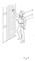
- Fig. 9 is a view showing a first manner of usage for the static eliminator according to the first embodiment of the present invention.
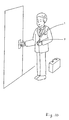
- Fig. 10 is a view showing a second manner of usage for the static eliminator according to the first embodiment of the present invention.
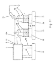
- Fig. 11 is a view showing the configuration of an experimental device in order to confirm the effect upon absorption of static electricity to be achieved by the static eliminator according to the first embodiment of the present invention.
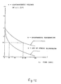
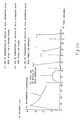
- Fig. 12 is a graph showing the effect upon a periodic decrease in static electricity on the basis of the experimental results gained by the experimental device as shown in Fig. 11.
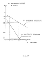
- Fig. 13 is a graph showing a static electricity attenuation factor characteristic on the basis of the experimental results gained by the experimental device as shown in Fig. 11.
- Fig. 14 is a wave-form view of static electricity showing the effect upon reduction of static electricity gained by the experiment with the experimental device of Fig. 11, which records and displays observation results of static electricity by a pen recorder while varying settings of charging levels, a first manner of usage for the static eliminator according to the first embodiment of the present invention.
- Fig. 15 is a perspective view showing a housing portion of a static eliminator according to a second embodiment of the present invention.
- Fig. 16 is a wiring diagram showing the configuration of an electrical circuit of the static eliminator according to the second embodiment of the present invention.
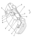
- Fig. 17 is a view showing a layout configuration of the static eliminator according to the second embodiment of the present invention, when applied to a body of a car.
- Fig. 18 is an enlarged perspective view showing an essential portion of Fig. 17.
- Fig. 19 is a perspective view showing a housing portion of a static eliminator according to a third embodiment of the present invention.
- Fig. 20 is a wiring diagram showing the configuration of an electrical circuit according to the third embodiment of the present invention.
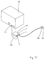
- Fig. 21 is a perspective view showing a status of usage of the static eliminator according to the third embodiment of the present invention.
- Fig. 23 is a plane view in an open lid status, showing the configuration of a first example of a static electricity eliminating device according to the fourth embodiment of the present invention.
- Fig. 25 is a plane view in an open lid status, showing the configuration of a second example of a static electricity eliminating device according to the fourth embodiment of the present invention.
- Fig. 26 is a view in section taken along line D-D of Fig. 25.
- Fig. 27 is a perspective view showing the configuration of the second example of the static electricity eliminating device according to the fourth embodiment of the present invention.
- Fig. 28 is a plane view in an open lid status, showing the configuration of a third example of a static electricity eliminating device according to the fourth embodiment of the present invention.
- Fig. 29 is a view in section taken along line E-E of Fig. 28.
- Fig. 30 is a perspective view showing the configuration of the third example of the static electricity eliminating device according to the fourth embodiment of the present invention.
- Fig. 31 is a view showing a manner of display by an electrostatic potential display section of an electrostatic potential display device of the static eliminator according to the fourth embodiment of the present invention.
- the Leyden jars 75 and 75 were charged each to a potential as high as (-)7,000 V by a Van de Graaff electrostatic generator and an earth plug socket 3 of the static eliminator of this embodiment is connected to electrodes 78 and 78 of the respective Leyden jars 75 and 75 through an earth wire 10A, thereby discharging accumulated charges having a potential of (-) 7,000 V within the Leyden jars 75 and 75.
- the potentials of the electrodes were measured by an electrometer 79 fifteen times for every ten seconds to determine a periodic decrease-of the electrode potential (experiment a).
- the earth line 10A is connected after the Leyden jars 75 and 75 were charged each to a potential as high as (-)7,000 V, it is possible to charge the Leyden jars 75 and 75 while the earth line 10A has been connected to the electrodes 78 and 78 of the Leyden jars 75 and 75 from the first time, respectively, if a supply power switch 4 of the static electricity eliminator is turned off. In this case, simply by turning the supply power switch 4 on after completion of charging, the same experiment as described hereinabove can be repeated easily.
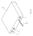
- Fig. 15 indicating the structure of a box-shaped housing portion 90 of the static eliminator to be loaded onto the car, it is shown that the housing 90 is provided with mounting edge portions 91 and 92 suitable so as to be mounted in a trunk room of the body of the car as shown in Fig. 17.
- a connecter a wire-harness coupler
- a connecter having a four-terminal structure, an electrical field line short-circuit switch 5, and a light-emitting diode 14, each projecting therefrom.
- the static electricity elimination circuit is configured in such a fashion that its basic portion has the same configuration as the circuit according to the first embodiment of the present invention as shown in Fig. 2 and that a supply power circuit portion has a configuration different to some extent from the circuit thereof because the car is loaded with a battery 98 of (+)12 V as a supply power.
- the ignition key switch (IG-SW) 97 is turned OFF from its ON status in usual cases.
- the static electricity elimination circuit plays the entirely equal action as the circuit as shown in Fig. 2 according to the first embodiment of the present invention, thereby rapidly lowering the charged potential to the potential lower than the discharged potential at the portions of the door outer handle 99, the door key cylinder 100 and the belt line mole 101, each being most likely to give an electrical shock to the human body, by the aid of the first through fourth static electricity elimination devices and the static electricity elimination function of the third arrestor 18.
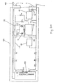
- Fig. 19 indicates the structure of a portion of a housing 105 of the static electricity eliminator according to this embodiment of the present invention.
- an earth plug socket 3 On a front side portion of the housing 105 are disposed an earth plug socket 3, an electrical field line short-circuit switch 5, a supply power switch 4 and an AC power plug 10, in a similar way as the static electricity eliminator according to the first embodiment of the present invention.
- housing 105 Inside the housing 105 are accommodated and disposed in an appropriate fashion a variety of electrical and electronic parts and wiring tools constituting the static electricity elimination circuit, for example, as shown in Fig. 20.
- the DC regulated supply power 109 is connected to the AC supply power 107 through an AC supply power plug 106 in substantially the same manner as in Fig. 21.
- the earth line 16 is connected from the earth plug socket 3 through an earth wiring 108 for eliminating static electricity to an earth terminal 111 of an electrical or electronic equipment 110 readily likely to be charged, such as an objective electrostatic treatment device, an office automation equipment, an electronic oven or the like.
- the static electricity eliminator having the configuration as described hereinabove is configured such that a charged potential from the electrical or electronic equipment 110 is led through the earth wiring 108 to the earth line 16 of the static electricity elimination circuit as shown in Fig. 20 and it is effectively removed by effectively discharging and neutralizing positive and negative ions in the electrical field by each of the first through fourth static electricity elimination devices 20, 40, 60 and 70 as well as the first arrestor 17 in substantially the same manner as in the first embodiment of the present invention.
- the experimental method includes a method for investigating abnormality of an electrical device, as a first method, by discharging electricity (DC -20 kV) to the electrical device connected with the ground.
- the static electricity eliminator according to the embodiment of the present invention has the action to alleviate an impact of electrostatic discharging and to enhance the ability of discharging as well as to effectively prevent problems to occur in electrical equipment due to static electricity.
- Figs. 22 to 31 indicate a configuration of the static electricity eliminator according to the fourth embodiment of the present invention in which no battery supply power is utilized at all unlike the first embodiment of the present invention, in the case where the static eliminator is constituted, for example, as a portable static eliminator for use for the human body in a way similar to the first embodiment thereof.
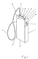
- Fig. 22 indicates the structure of a housing portion of the portable static electricity eliminator according to the embodiment of the present invention, in which reference numeral 1 denotes a housing of a box shape having a size suitable for accommodation in a pocket or suitable for holding by a hand, in a manner similar to that according to the first embodiment of the present invention.
- the box-shaped housing 1 comprises a body section 2 having a predetermined depth and a lid (not shown) to be detachably attached to an open side of the body section 2.
- an electrical field electrode plug 121 of a flush type On an upper end side portion 2a of the body section 2 of the box-shaped housing 1 are disposed an electrical field electrode plug 121 of a flush type, an electrical field electrode plug 123 of a key holder type, and a connection jack for connecting an object, which are arranged in left and right directions at predetermined intervals.
- the electrical field electrode plug 121 of a flush type is fixed on an electrode plate 121b connected to a first internal static electricity elimination line 131 so as to cover a urethan foam 121a through an electrically conductive rubber.
- The. object connection jack 124 can be employed for insertion of a plug for an external wiring connecting an object to be connected to an object connecting the human body with the ground, such as a heel strap or the like known in the art as a tool for connecting the human body with the ground.
- the electrical field electrode plug 123 of a key holder type is provided with a ring 123a for mounting a key holder and employed by mounting a key, for example, on a door or the body of a car.
- the earth chain 130 is connected to the earth chain connection substrate plate 122a of the earth chain connection portion 122.
- the earth chain 130 is mounted, for example, on part of the human body and connected to the human body.
- the earth chain connection substrate plate 122a is connected in its inside to the earth line 140 and the first through third internal wiring 137 through 139 inside the object, respectively.
- the object connection jack 124 is connected to the electrical field electrode plug 123 of the key holder type through the seventh internal wiring 133 inside the object.
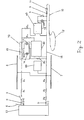
- Figs. 23 and 24 indicate the configuration of the first static electricity elimination device 126.
- reference numeral 126a denotes a box-shaped casing made of a non-electrically conductive synthetic resin and it is provided with a lid (not shown). Inside the casing 126a are disposed a heater 141 of a multiple structure, a first arrestor 142 and a second arrestor 143, each having a structure of a Harrison's discharge tube with gases capable of absorbing electrostatic surge filled therein, a first discharging plate 144 consisting of a iron string block having a predetermined diameter and length, a second discharging plate 145 consisting of a copper plate block having a predetermined thickness, and the like.
- the other end of the first discharging plate 144 is connected to one end of the NichromeTM wire coil 141f through the first arrestor 142 and to the fourth internal wiring 134 inside the object.
- the second arrestor 143 is connected to the second static electricity elimination line 132a and the other end of the NichromeTM wire coil 141f in a row through resistance R22 (30 k ⁇ ) and resistance R23 (30 k ⁇ ).
- the corona discharge electrode consisting of the first and second discharging plates 144 and 145 as well as the pin electrodes 145a and 145a. If the charged voltage is high to such an extent as incapable of being lowered by the three actions as described immediately hereinabove, the positive and negative ions are neutralized by causing corona discharging between the first discharging plate 144 and the pin electrodes 145a and 145a of the second discharging plate 145, thereby reducing and lowering the electrostatic voltage to a sufficiently low extent.
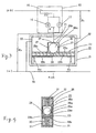
- Figs. 25 to 28 indicate the details of the configuration of the second static electricity elimination device 127.
- reference numeral 127b denotes a box-shaped casing made of a non-electrically conductive synthetic resin and it is provided with a lid 127a.
- the casing 127b is divided into one larger compartment and two smaller compartments by the first and second partition walls 148 and 149, each made of a synthetic resin.
- a rectangular electrode 146 made of a copper material and a spherical electrode 147 made of an iron material are disposed and fixed in its central portion in such a state as facing each other in a predetermined discharging gap and pumice and granitic earths 31 are filled around them.
- a spherical electrode 150 made of iron is disposed and fixed in a nearly central portion.
- the iron electrode 150 is connected to one end of the fifth internal wiring 135 inside the object.
- first and second neon electrodes 149a and 149b each in a bar shape, so as to coaxially face each other in a predetermined discharging gap.
- the first neon electrode 149a on one end side is connected to the fifth internal wiring 135 inside the object in substantially the same manner as the iron electrode 150 on the one end side.
- the second neon electrode 149 on the other end side is connected to the iron electrode 150 on the other end side and a U-shaped NichromeTM wire coil 160 as well as to the third static electricity elimination line 132 through the NichromeTM wire coil 160.
- the static electricity from the charging object introduced from the electrical field electrode plug 121 of the flush type or the static electricity elimination chain connection jack 163 through each of the first and third static electricity elimination lines 131 and 132b is applied to each of the copper electrode 146 and the iron electrode 147 causing the corona discharging between the electrodes 146 and 147 in any case and the ions generated can effectively be absorbed and neutralized by the pumice and granitic earths 31 around them.
- one end of the iron electrode 150 having a smaller diameter and one end of the first neon electrode 149a are connected to a human body earthing tool for connection of the human body with the ground through the fifth internal wiring 135 inside the object. Further, the other end of the iron electrode 150 having a smaller diameter and the other end of the first neon electrode 149a are connected to the NichromeTM wire coil 160 and the static electricity introduced from the third static electricity elimination line 132 is applied. The static electricity is first consumed as heat by the NichromeTM wire coil 160 and discharged into air around the iron electrode 150 having a smaller diameter. At the same time, the corona discharging is caused between the first and second neon electrodes 149a and 149b and then eliminated.
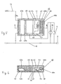
- Figs. 28 to 30 indicate the details of the configuration of the third static electricity elimination device 128.
- reference numeral 128b denotes a box-shaped casing made of a non-electrically conductive synthetic resin and it is provided with a lid 128a.
- the casing 128b there are disposed a heater 151, an arrestor 152, a discharging plate 153 made from a copper plate block having a predetermined thickness, as well as a discharging electrode consisting of counter electrode plates 154 and 156, each in the form of a flat stainless steel plate, as shown in the drawings.
- the heater 151 is formed in such a shape that. NichromeTM wire coil 151b is wound on a core 151a made of an acrylic resin.
- the arrestor 152 is of a structure of a Harrison discharge tube containing gases capable of absorbing electrostatic surge.
- the discharging electrode is formed such that the counter electrode plates 154 and 156 are disposed facing each other at a predetermined interval with the aid of spacers 155 made of an acrylic resin. Further, the counter electrode plate 154 of the discharging electrode is connected to one end of the NichromeTM wire coil 151 through resistance R24 and the counter electrode plate 156 is connected to the other end of the NichromeTM wire coil 151 through resistance R23.
- the arrestor 152 having the structure of the Harrison discharge tube with the such gases filled therein is connected to the both ends of the NichromeTM wire coil 151b of the heater 151.
- corona discharging is caused to occur with the discharging plate 153 connected to the fifth internal wiring 136 inside the object.
- the resistances R23 and R24 have each a resistance value of, for example, approximately 30 k ⁇ and has the actions of dividing the static electricity into smaller sections and lowering the voltage.
- the discharging plate 153 is disposed so as to cause discharging by itself (usually on the side of a tool for connection with the ground), if static electricity would be applied through the sixth internal wiring 136 inside the object. As a result, a sufficient amount of static electricity is eliminated.
- the static eliminator according to this embodiment has each of the counter electrode plates 154 and 156 formed particularly having a wide area so that it can discharge readily (dark discharging possible). Therefore, it can compete with a low level of electrostatic voltage to a sufficient extent if a discharging gap therebetween would be made smaller. It can be said in this respect to be of a type suitable for a low electrostatic voltage.
- Fig. 31 indicates the configuration of a display section 129a of the electrostatic potential display device 129 as shown in Fig. 22.
- the electrostatic potential display device 129 comprises, for example, a liquid crystal display device.
- the display section 129a is configured in such a way that the words "OVER 3000 V" are displayed as shown in the drawing when an electrostatic potential higher than DC -3,000 V required for elimination of static electricity is applied by the first static electricity elimination line 131 and that this display automatically disappears when the electrostatic potential is lowered below that displayed level by the action for eliminating static electricity.
- the display can be arranged so as to display, for example, a specific figure of electrostatic potential itself.
- the measurement is carried out for a case (b) in which the static eliminator is solely employed and for each of cases (c) through (e) in which the object wiring is employed for connection to a heel strap and it is employed at varying locations.
- connection of the object connection jack 124 to a tool for connection of the human body with the ground by using the object wiring can offer a higher effect.
- the static eliminator according to the present invention is effective as a carrying part for personal use for eliminating static electricity or a device to be loaded in a car or as a device for preventing static electricity from being charged onto a person at work in IC plants, LSI plants or the like.
Description
Claims (5)
- A static electricity eliminator comprising a static electricity introduction means (16) for introducing static electricity from a charging object and a static electricity elimination means (20, 40) for eliminating static electricity introduced via said static electricity introduction means (16),
characterized in that :said static electricity elimination means comprises a discharging means (26, 43) for discharging the static electricity and an exothermic means (23, 48) for eliminating the static electricity;said static electricity elimination means comprises a plurality of groups each comprised of a combination of a discharging means and an exothermic means and having varying performance for eliminating static electricity in association with a magnitude of electrostatic voltage charged onto the charging object;said exothermic means is formed in a structure of a heater capable of generating Joule's heating by static electricity. - A static electricity eliminator as claimed in claim 1, characterized in that said discharging means (26, 43) is enclosed by granitic earths (31).
- A static electricity eliminator as claimed in claim 1, characterized in that said exothermic means (23, 48) is enclosed by granitic earths.
- A static electricity eliminator as claimed in claim 1, characterized in that said discharging means (26, 43) and exothermic means (23, 48) are each enclosed by granitic earths (31).
- A static electricity eliminator as claimed in claim 1, 2 or 4, characterized in that said discharging means (26, 43) is formed in a structure of a discharging electrode causing corona discharging by static electricity.
Applications Claiming Priority (4)
| Application Number | Priority Date | Filing Date | Title |
|---|---|---|---|
| JP2061/94 | 1994-01-13 | ||
| JP206194 | 1994-01-13 | ||
| JP206194 | 1994-01-13 | ||
| PCT/JP1995/000010 WO1995019690A1 (en) | 1994-01-13 | 1995-01-10 | Static eliminator |
Publications (3)
| Publication Number | Publication Date |
|---|---|
| EP0695114A1 EP0695114A1 (en) | 1996-01-31 |
| EP0695114A4 EP0695114A4 (en) | 1996-02-14 |
| EP0695114B1 true EP0695114B1 (en) | 2004-05-19 |
Family
ID=11518836
Family Applications (1)
| Application Number | Title | Priority Date | Filing Date |
|---|---|---|---|
| EP95905233A Expired - Lifetime EP0695114B1 (en) | 1994-01-13 | 1995-01-10 | Static electricity eliminator |
Country Status (5)
| Country | Link |
|---|---|
| US (1) | US5719739A (en) |
| EP (1) | EP0695114B1 (en) |
| DE (1) | DE69533052T2 (en) |
| TW (1) | TW301524U (en) |
| WO (1) | WO1995019690A1 (en) |
Cited By (1)
| Publication number | Priority date | Publication date | Assignee | Title |
|---|---|---|---|---|
| US7946522B2 (en) | 2006-10-30 | 2011-05-24 | Kimberly-Clark Worldwide, Inc. | System and method for dissipating static electricity in an electronic sheet material dispenser |
Families Citing this family (20)
| Publication number | Priority date | Publication date | Assignee | Title |
|---|---|---|---|---|
| ATE379847T1 (en) | 1999-07-02 | 2007-12-15 | Matsushita Electric Ind Co Ltd | ARRANGEMENT FOR PRODUCING SOLDER BUMPS ON SEMICONDUCTOR SUBSTRATES GENERATING ELECTRICAL CHARGES, METHOD AND ARRANGEMENT FOR REMOVAL OF THESE CHARGES, AND ELECTRICAL CHARGE GENERATING SEMICONDUCTOR SUBSTRATE |
| WO2001009999A1 (en) * | 1999-07-30 | 2001-02-08 | Illinois Tool Works Inc. | Ionizer for static elimination in variable ion mobility environments |
| US6574086B2 (en) * | 2000-06-15 | 2003-06-03 | Illinois Tool Works Inc. | Static eliminator employing DC-biased corona with extended structure |
| KR20050028190A (en) * | 2003-09-17 | 2005-03-22 | 엘지전자 주식회사 | A leakage current interception formation of refrigerator door |
| CN100439836C (en) * | 2004-09-20 | 2008-12-03 | 乐金电子(天津)电器有限公司 | Leakage current stop structure for refrigerator door |
| US7267430B2 (en) * | 2005-03-29 | 2007-09-11 | Lexmark International, Inc. | Heater chip for inkjet printhead with electrostatic discharge protection |
| US7327547B1 (en) * | 2006-01-20 | 2008-02-05 | Epstein Barry M | Circuit element and use thereof |
| US20070171592A1 (en) * | 2006-01-26 | 2007-07-26 | Lee Wen S | Device for removing static charge |
| US7361966B2 (en) * | 2006-02-13 | 2008-04-22 | Lexmark International, Inc. | Actuator chip for inkjet printhead with electrostatic discharge protection |
| US8264811B1 (en) | 2009-03-05 | 2012-09-11 | Richard Douglas Green | Apparatus for the dispersal and discharge of static electricity |
| CN102036459A (en) * | 2009-09-25 | 2011-04-27 | 深圳富泰宏精密工业有限公司 | Grounding device and portable electronic device applying same |
| US8553055B1 (en) | 2011-10-28 | 2013-10-08 | Graphic Products, Inc. | Thermal printer operable to selectively control the delivery of energy to a print head of the printer and method |
| US8477162B1 (en) | 2011-10-28 | 2013-07-02 | Graphic Products, Inc. | Thermal printer with static electricity discharger |
| US8482586B1 (en) | 2011-12-19 | 2013-07-09 | Graphic Products, Inc. | Thermal printer operable to selectively print sub-blocks of print data and method |
| US9908733B2 (en) | 2012-12-20 | 2018-03-06 | 3M Innovative Properties Company | Static reduction roller and method for reducing static on a web |
| CN103982608B (en) * | 2013-02-07 | 2016-12-28 | 盖茨优霓塔传动系统(上海)有限公司 | Tension-adjusting gear |
| JP6167083B2 (en) * | 2014-09-09 | 2017-07-19 | アンリツ株式会社 | Static elimination device and static elimination method |
| US9751444B2 (en) | 2015-12-07 | 2017-09-05 | Robert Leon Dickerman | Electrostatic discharge mitigator for vehicles |
| JP6558313B2 (en) * | 2016-06-29 | 2019-08-14 | トヨタ自動車株式会社 | Vehicle and manufacturing method thereof |
| JP6665732B2 (en) * | 2016-08-23 | 2020-03-13 | 株式会社デンソー | Static electricity suppressing device, static electricity suppressing method |
Family Cites Families (10)
| Publication number | Priority date | Publication date | Assignee | Title |
|---|---|---|---|---|
| US3984730A (en) * | 1975-07-11 | 1976-10-05 | The Unites States Of America As Represented By The Administrator Of The National Aeronautics And Space Administration | Method and apparatus for neutralizing potentials induced on spacecraft surfaces |
| DE2822228A1 (en) * | 1978-05-22 | 1979-11-29 | Kigass Engineering Ltd | ANTI-STATIC DEVICE |
| JPS58103500U (en) * | 1982-01-08 | 1983-07-14 | 石山 舎人 | Static remover |
| FR2590103B1 (en) * | 1985-11-13 | 1991-07-05 | Cables De Lyon Geoffroy Delore | DEVICE FOR ELIMINATING ELECTROSTATIC CHARGES ON A HIGH SPEED MOBILE VEHICLE |
| US4849851A (en) * | 1988-10-31 | 1989-07-18 | American Telephone And Telegraph Company | Static electric discharge apparatus with active electrical circuit |
| US5095400A (en) * | 1988-12-06 | 1992-03-10 | Saito Kohki Co., Ltd. | Method and apparatus for eliminating static electricity |
| EP0386318B1 (en) * | 1989-03-07 | 1994-07-20 | Takasago Thermal Engineering Co. Ltd. | Equipment for removing static electricity from charged articles existing in clean space |
| WO1992020201A1 (en) * | 1991-04-25 | 1992-11-12 | Bakhoum Ezzat G | A ground-free static charge removal device |
| US5247420A (en) * | 1991-04-25 | 1993-09-21 | Bakhoum Ezzat G | Ground-free static charge indicator/discharger |
| EP0551668A1 (en) * | 1992-01-14 | 1993-07-21 | Melton Enterprises Ltd. | Resonators eliminating the harmful effects on living beings from electromagnetic radiation generated by cathode ray tubes and other sources of electromagnetic radiation, and method for use of such resonators |
-
1995
- 1995-01-10 US US08/530,124 patent/US5719739A/en not_active Expired - Fee Related
- 1995-01-10 WO PCT/JP1995/000010 patent/WO1995019690A1/en active IP Right Grant
- 1995-01-10 EP EP95905233A patent/EP0695114B1/en not_active Expired - Lifetime
- 1995-01-10 DE DE69533052T patent/DE69533052T2/en not_active Expired - Fee Related
- 1995-01-12 TW TW085208496U patent/TW301524U/en unknown
Cited By (1)
| Publication number | Priority date | Publication date | Assignee | Title |
|---|---|---|---|---|
| US7946522B2 (en) | 2006-10-30 | 2011-05-24 | Kimberly-Clark Worldwide, Inc. | System and method for dissipating static electricity in an electronic sheet material dispenser |
Also Published As
| Publication number | Publication date |
|---|---|
| EP0695114A4 (en) | 1996-02-14 |
| US5719739A (en) | 1998-02-17 |
| WO1995019690A1 (en) | 1995-07-20 |
| EP0695114A1 (en) | 1996-01-31 |
| DE69533052T2 (en) | 2005-05-12 |
| TW301524U (en) | 1997-03-21 |
| DE69533052D1 (en) | 2004-06-24 |
Similar Documents
| Publication | Publication Date | Title |
|---|---|---|
| EP0695114B1 (en) | Static electricity eliminator | |
| JP2003526484A (en) | Personal body grounding device | |
| HUP0000345A2 (en) | Method and apparatus incorporating air modifying agents | |
| US10507749B1 (en) | Electrostatic discharge mitigator for vehicles | |
| CN100356821C (en) | Electrostatic eliminator | |
| KR890009423A (en) | Method and method of minimizing skin injury using electrodes | |
| AT408608B (en) | Device intended particularly for massaging the genitals | |
| JPH07245191A (en) | Electrostatic eliminating apparatus | |
| EP0569920A1 (en) | Portable device for thermal stimulus sensitivity tests | |
| JP4773474B2 (en) | Fine adsorption device | |
| RU2669907C2 (en) | Method for elimination of painful sensations in case of capacitive breakdown in electric shock devices and device for implementation of such method | |
| JP2004057811A (en) | Electrostatic body conditioner | |
| JP4225778B2 (en) | Relaxation assist device | |
| JPH0894501A (en) | Electostatic minute object collector | |
| Lunt | Safety With Electricity | |
| JPS6458266A (en) | Potential loading method in potential treatment | |
| KR200249600Y1 (en) | A key for a car discharge an static electricity | |
| CN106024452B (en) | It is grounded smart locking device | |
| ES488212A1 (en) | Heating vehicles electrically | |
| JPS6473364A (en) | Contact electrifying device | |
| Ricketts | The Case of the FATAL GROUND FAULT | |
| Champion et al. | The Application of the Preparatory‐Response Hypothesis to Changes in Base Skin Resistance | |
| US4482856A (en) | Battery charger | |
| Zacher | New charged-plate monitor design offers greater flexibility | |
| RU2008942C1 (en) | Device for electrotherapeutics |
Legal Events
| Date | Code | Title | Description |
|---|---|---|---|
| PUAI | Public reference made under article 153(3) epc to a published international application that has entered the european phase |
Free format text: ORIGINAL CODE: 0009012 |
|
| AK | Designated contracting states |
Kind code of ref document: A1 Designated state(s): DE FR GB |
|
| A4 | Supplementary search report drawn up and despatched | ||
| AK | Designated contracting states |
Kind code of ref document: A4 Designated state(s): DE FR GB |
|
| 17P | Request for examination filed |
Effective date: 19951017 |
|
| 17Q | First examination report despatched |
Effective date: 20020524 |
|
| GRAP | Despatch of communication of intention to grant a patent |
Free format text: ORIGINAL CODE: EPIDOSNIGR1 |
|
| RTI1 | Title (correction) |
Free format text: STATIC ELECTRICITY ELIMINATOR |
|
| GRAS | Grant fee paid |
Free format text: ORIGINAL CODE: EPIDOSNIGR3 |
|
| GRAA | (expected) grant |
Free format text: ORIGINAL CODE: 0009210 |
|
| AK | Designated contracting states |
Kind code of ref document: B1 Designated state(s): DE FR GB |
|
| REG | Reference to a national code |
Ref country code: GB Ref legal event code: FG4D |
|
| REF | Corresponds to: |
Ref document number: 69533052 Country of ref document: DE Date of ref document: 20040624 Kind code of ref document: P |
|
| ET | Fr: translation filed | ||
| PLBE | No opposition filed within time limit |
Free format text: ORIGINAL CODE: 0009261 |
|
| STAA | Information on the status of an ep patent application or granted ep patent |
Free format text: STATUS: NO OPPOSITION FILED WITHIN TIME LIMIT |
|
| 26N | No opposition filed |
Effective date: 20050222 |
|
| PGFP | Annual fee paid to national office [announced via postgrant information from national office to epo] |
Ref country code: GB Payment date: 20080109 Year of fee payment: 14 Ref country code: DE Payment date: 20080104 Year of fee payment: 14 |
|
| PGFP | Annual fee paid to national office [announced via postgrant information from national office to epo] |
Ref country code: FR Payment date: 20080108 Year of fee payment: 14 |
|
| GBPC | Gb: european patent ceased through non-payment of renewal fee |
Effective date: 20090110 |
|
| PG25 | Lapsed in a contracting state [announced via postgrant information from national office to epo] |
Ref country code: DE Free format text: LAPSE BECAUSE OF NON-PAYMENT OF DUE FEES Effective date: 20090801 |
|
| REG | Reference to a national code |
Ref country code: FR Ref legal event code: ST Effective date: 20091030 |
|
| PG25 | Lapsed in a contracting state [announced via postgrant information from national office to epo] |
Ref country code: GB Free format text: LAPSE BECAUSE OF NON-PAYMENT OF DUE FEES Effective date: 20090110 |
|
| PG25 | Lapsed in a contracting state [announced via postgrant information from national office to epo] |
Ref country code: FR Free format text: LAPSE BECAUSE OF NON-PAYMENT OF DUE FEES Effective date: 20090202 |