EP0695101A1 - Mobile radio communication system and radio receiver - Google Patents
Mobile radio communication system and radio receiver Download PDFInfo
- Publication number
- EP0695101A1 EP0695101A1 EP95907825A EP95907825A EP0695101A1 EP 0695101 A1 EP0695101 A1 EP 0695101A1 EP 95907825 A EP95907825 A EP 95907825A EP 95907825 A EP95907825 A EP 95907825A EP 0695101 A1 EP0695101 A1 EP 0695101A1
- Authority
- EP
- European Patent Office
- Prior art keywords
- paging
- transmissions
- signal
- transmitted
- paging signals
- Prior art date
- Legal status (The legal status is an assumption and is not a legal conclusion. Google has not performed a legal analysis and makes no representation as to the accuracy of the status listed.)
- Granted
Links
Images


Classifications
-
- H—ELECTRICITY
- H04—ELECTRIC COMMUNICATION TECHNIQUE
- H04W—WIRELESS COMMUNICATION NETWORKS
- H04W88/00—Devices specially adapted for wireless communication networks, e.g. terminals, base stations or access point devices
- H04W88/18—Service support devices; Network management devices
- H04W88/185—Selective call encoders for paging networks, e.g. paging centre devices
- H04W88/187—Selective call encoders for paging networks, e.g. paging centre devices using digital or pulse address codes
-
- H—ELECTRICITY
- H04—ELECTRIC COMMUNICATION TECHNIQUE
- H04W—WIRELESS COMMUNICATION NETWORKS
- H04W88/00—Devices specially adapted for wireless communication networks, e.g. terminals, base stations or access point devices
- H04W88/18—Service support devices; Network management devices
Definitions
- This invention is utilized for calling radio receivers, and relates in particular to a mobile communications system which repeatedly transmits a signal for selectively calling a receiver, and to said receiver.
- Fig.1 shows an example of the overall constitution of a selective radio paging system.
- This system has central station 1 and a plurality of base stations 2; and a paging signal sequence is transmitted from central station 1 to base stations 2 via links, with these base stations 2 transmitting said paging signal sequence through the air by radio waves.
- Receiving terminal 3 in the service area receives the paging signal sequence that has been transmitted from base stations 2, and performs paging operations when there is a paging signal addressed to it.
- Fig.9 shows a conventional selective paging sequence which base stations 2 transmit.
- the paging signal sequence comprises a series of superframes of period T , each comprising n frames of signal length p joined together.
- the signal corresponding to each frame comprises a synchronization signal and a series of paging signals.
- the sequences with period T are sometimes called "frames" and the sequences comprising a synchronization signal plus a series of paging signals are sometimes called "subframes".
- the receiving terminals are divided into n groups, and a receiving terminal belonging to group i ( 1 ⁇ i ⁇ n ) becomes capable of receiving only during a frame i reception time, whereupon it receives the paging signals in that frame.
- the received signal is a paging signal for the receiving terminal in question, that receiving terminal performs paging operations.
- a system whereby a receiving terminal becomes capable of receiving only during the frame reception time allotted to said terminal is called an "intermittent receiving system", and achieves an extension of battery life.
- Fig.9(b) shows frames transmitted to receiving terminals belonging to group i , for the case where identical paging signals are transmitted twice.
- frame i transmitted at time t0 the synchronization signal is followed by transmission of paging signal a for the second time and paging signals b and c for the first time.
- time t0 + T which is the next transmission time
- the synchronization signal is followed by transmission of paging signals b and c for the second time and paging signal d for the first time.
- time t0 + 2T which is the next transmission time
- the synchronization signal is followed by transmission of paging signal d for the second time and paging signal e for the first time.
- the probability of correctly receiving is further increased by time diversity reception, at the receiving side, of identical paging signals that have been transmitted a plurality of times.
- One time diversity method involves using the detector output for each bit as taught in Hirai, Y., Nozawa, T. and Itö, S., "BER performance with thime diversity reception in digital FM mobile radio" , Proceedings of the 1993 Spring Conference of the IEICE Japan, B-330; and in Jap. Pat. Appl. No.5-117216 and P C T/JP94/00400 which is based on this Japanese application.
- PCT/JP94/00107 teaches constituting frames from a plurality of fixed-length subframes; inserting a new paging signal at one end within the frame (for example, in the leading subframe); and inserting a paging signal that is to be transmitted for the second or subsequent time in a subframe arranged at a position corresponding to said number of times.
- a mobile communications system is characterised in that, in a mobile communications system which has a transmitting means which transmits paging signals a plurality of times through the air by radio waves, said paging signals serving to selectively page radio receivers: there is provided a means which variably sets the number of times that paging signals are transmitted from the transmitting means. There should be a means which transmits, from the transmitting means, information relating to the number of times that paging signals are transmitted. When the transmitting means transmits in units of frames, said frames comprising one or more paging signals to which a control signal has been added, the information relating to the number of transmissions should be inserted in this control signal.
- the radio receivers should have: a means which recognises the number of times that paging signals from the transmitting means will be transmitted; a means which, on the basis of the recognition output of this recognition means, recognises the number of times that paging signals will be received; and a means which, on the basis of the recognition output of this recognition means, sets the number of times that paging signals will be received.
- the radio receivers should have: a means which recognises the number of times that paging signals from the transmitting means will be transmitted; a means which, on the basis of the recognition output of this recognition means, recognises the number of times that paging signals will be received; and a means which, on the basis of the recognition output of this recognition means, sets the number of times that paging signals will be received.
- the method disclosed in Jpn. Pat. Appl. Kökai No.2-44821 can be utilized after modification. Namely, instead of transmitting after adding information relating to how many times the paging signals in the frame in question will have been transmitted, transmitting is carried out after adding information relating to how many times its paging signals will subsequently be transmitted, and the initial value of a countdown is changed accompanying a change in the number of transmissions. By proceeding in this way, the number of times each paging signal will subsequently be sent can be recognised at a radio receiver from the received frame, and it is not essential to recognise a change in the number of transmissions.
- the signal configuration disclosed in PCT/JP94/00107 is one in which the signal configuration within frames changes accompanying change in the number of transmissions.
- frames are constituted from a plurality of subframes of fixed length, and a new paging signal is inserted at one end of the frame (for example, in the leading subframe), while a paging signal that is to be transmitted for the second or subsequent time is inserted in a subframe arranged at a position corresponding to said number of times.
- a new paging signal is inserted at one end of the frame (for example, in the leading subframe)
- a paging signal that is to be transmitted for the second or subsequent time is inserted in a subframe arranged at a position corresponding to said number of times.
- the transmitting side should have a means which forms n subframes within a frame when the number of transmissions is n ; and said means should include: a means which inserts a new paging signal in a subframe positioned at one end of said frame, and which inserts a paging signal that is to be transmitted for the second or subsequent time in a subframe arranged at a position corresponding to the number of times in question; and a means which changes the number and length of subframes within a frame when the setting means changes the number of transmissions n .
- the radio receiver should have: a means which detects, from the control signal of the received frame, information relating to the number of transmissions; and a means which decides the subframe configuration of said received frame from the detected information relating to the number of transmissions.
- regions in which the population is not so densely crowded can have the service area per base station enlarged by making the number of transmissions of identical paging signals greater than that in densely populated regions.
- densely populated regions as well, when there is little traffic (e.g., during the night), if the number of transmissions of identical paging signals is made greater than at ordinary times, a service with high quality transmission of paging signals can be achieved.
- Fig.1 block diagram showing an example of the overall constitution of a selective radio paging system.
- Fig.2 embodiment of the selective paging signal sequence transmitted by base stations.
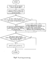
- FIG.3 flowchart of the operation of frame formation by the central station.
- Fig.4 block diagram showing an example of a radio receiver used as a receiving terminal.
- Fig.5 flowchart of the control of receiving processing by the decoder.
- Fig.6 another embodiment of the selective paging signal sequence transmitted by base stations.
- Fig.7 flowchart of the operation of frame formation by the central station.
- Fig.8 flowchart of the control of receiving processing by the decoder in the radio receiver.
- Fig.9 conventional selective paging signal sequence transmitted by base stations.
- Fig.1 is a block diagram showing a selective radio paging system which embodies this invention
- Fig.2 shows an embodiment of the selective paging signal sequence transmitted by the base stations.
- This selective radio paging system has a plurality of base stations 2 which serve as transmitting means which transmit paging signals a plurality of times through the air by radio waves, said paging signals serving to selectively page receiving terminal 3. It also has, in central station 1, a means which variably sets the number of times that paging signals are transmitted from these base stations 2.
- central station 1 forms frames comprising a synchronization signal, a control signal, and a series of paging signals, and transmits these via links to base stations 2.
- Base stations 2 transmit these frames through the air by radio waves.
- the control signal in each frame contains information indicating the number of transmissions, so that the state of the receiving terminal can be changed in accordance with the transmission parameters and mode that have been specified.
- the paging signal sequence comprises a sequence of superframes of period T , each comprising n frames of signal length p joined together. This is the same as the prior art example.
- the signal corresponding to each frame contains a control signal in addition to the synchronization signal and the series of paging signals.
- the number of transmissions is contained in the control signal.
- the receiving terminals are divided into n groups in similar fashion to the prior art example, and a receiving terminal belonging to group i ( 1 ⁇ i ⁇ n ) becomes capable of receiving only during a frame i reception time, whereupon it receives the paging signals in that frame.
- the received signal is a paging signal for a given receiving terminal, that receiving terminal performs paging operations.
- Fig.2 illustrates the case where the number of transmissions has been changed from two to three.
- the synchronization signal is followed by transmission of a control signal indicating that the number of transmissions is 2, and then by transmission of paging signal a for the second time, paging signal b for the first time, and paging signal c for the first time. It will be supposed that the number of transmissions has changed from 2 to 3.
- the synchronization signal is followed by transmission of a control signal indicating that the number of transmissions is 3, and then by transmission of paging signal a for the third time, paging signal b for the second time, and paging signal c for the second time.
- the synchronization signal is followed by transmission of a control signal indicating that the number of transmissions is 3, and then by transmission of paging signal b for the third time, paging signal c for the third time, and paging signal d for the first time.
- Fig.3 shows the flow of the operation of frame formation by central station 1.
- central station 1 when the number of transmissions has been set in a control signal, a comparison is made, for each paging signal transmitted the previous time, of the number of times said paging signal has been transmitted and the number of transmissions that have been set.
- the number of times a paging signal has been transmitted is equal to or greater than the number of transmissions that have been set, retransmission of that paging signal is stopped.
- the number of times a paging signal has been transmitted is smaller than the number of transmissions that have been set, that paging signal is retransmitted at the current transmission time.
- there is a new paging signal to be transmitted and this signal can be transmitted at the current transmission time said new paging signal is transmitted at said transmission time.
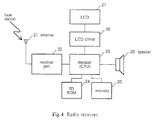
- Fig.4 is a block diagram showing an example of a radio receiver used as a receiving terminal.
- This radio receiver has antenna 21, receiver part 22, decoder 23, ID ROM 24, memory 25, liquid crystal display driver 26, liquid crystal display 27, and speaker 28.
- Receiver part 22 receives the paging signal sequence that is input via antenna 21 and supplies the received signal to decoder 23.
- Decoder 23 receives a synchronisation signal, performs synchronization processing, and uses the control signal, which is received next, to set the transmission parameters/mode of the receiver in question as specified by said control signal, whereupon it performs receiving processing of the subsequently received paging signals in accordance with this setting. Decoder 23 also performs the control required for the intermittent receiving, whereby receiver part 22 operates only during the times when the group to which it belongs is receiving.
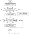
- Fig.5 shows the flow of the control of receiving processing by decoder 23.
- decoder 23 receives the number of transmissions in a control signal, it compares, for each paging signal transmitted the previous time, the number of times said paging signal has been received so far, and the received number of transmissions. When the number of receptions is equal to or greater than the number of transmissions, decoder 23 terminates the receiving processing of that paging signal. When the number of receptions is smaller than the number of transmissions, decoder 23 processes the paging signal in question as one which is to be received again at the current reception time.
- the number of transmissions - which is one of the parameters in the control signal - changes in the subframe received at time t0 + T to 3 from the previous setting of 2, and radio receivers belonging to group i change their receiving processing to match this. As a result, erroneous paging does not occur.
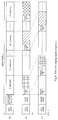
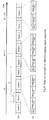
- Fig.6 shows another example of a paging signal sequence. This signal sequence is obtained by modifying the sequence disclosed in PCT/JP94/00107 so that it conforms with the present invention.
- each frame comprises a synchronization signal, a control signal, and a plurality of subframes.
- the number of transmissions n is inserted in the control signal.
- the subframes are established by dividing the region for paging signals within the frame into equal portions in accordance with the number of transmissions n , and each subframe is capable of transmitting a plurality of paging signals.
- Fig.6(b) represents the time t0 frame.
- Paging signals A , B and C are transmitted in the 1 st , m th , and n th subframes respectively, in accordance with how many times each has been transmitted.
- Fig.6(c) represents the frame at time t0 + T (the number of transmissions is n and has not changed). Because paging signal A will be transmitted for the second time, it is transmitted in the second subframe. Because paging signal B will be transmitted for the (m + 1) th time, it is transmitted in the (m + 1) th subframe. Because transmission of paging signal C for the n th time was completed at time t0 , it is not transmitted at time t0 + T . Because paging signal D will have its first transmission at time t0 + T , it is transmitted in the first subframe.
- the number of subframes in a frame can be set to a fixed number equal to the maximum value of the number of transmissions n , whereupon only the same number of subframes as the number of transmissions n are used.
- the number of transmissions n is smaller than the maximum value, there will be a wasted region in the frame.
- the number and length of subframes in the frame should therefore be changed in response to a change in the number of transmissions n , and the subframes should be set by dividing the region for paging signals by the changed number of transmissions n .
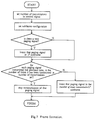
- Fig.7 shows the flow of the operation of frame formation by central station 1 when such a paging signal sequence is used.
- central station 1 when the number of transmissions has been set in a control signal, a subframe configuration - namely, the number and length of the subframes - corresponding to this number of transmissions will be set.
- this paging signal is inserted in the first subframe.
- a comparison is then made, for each paging signal transmitted the previous time, of the number of times said paging signal has been transmitted and the number of transmissions that have been set.
- Fig.8 shows the flow of the control of receiving processing by decoder 23 of the radio receiver when the paging signal sequence depicted in Fig.6 is used.
- decoder 23 receives the number of transmissions in a control signal, it recognises the subframe configuration corresponding to this number of transmissions and performs receiving processing appropriate to this. This involves performing reception termination processing on the paging signals which were received in those subframes transmitted the previous time that had a subframe number corresponding to or greater than the number of transmissions. Paging signals received in other subframes are processed as ones which, at the current reception time, are received in subframes with the following number.
- Decoder 23 then compares the address of the received paging signal with its own ID stored in ID ROM 24, and if these are in agreement and the paging signal in question has been correctly received for the first time, it causes speaker 28 to emit an alert and performs paging processing whereby the required information - such as a message - contained in the paging signal is displayed by liquid crystal display 27 via liquid crystal display driver 26.
- information relating to the number of transmissions is transmitted in each frame as one parameter of the control signal, said control signal serving to change the state of the receiving terminal in accordance with the transmission parameters/mode that have been set. This enables the number of transmissions to be changed for each group of receivers. Information relating to number of transmissions can also be inserted in a paging signal.
- a mobile communications system and a radio receiver enable the number of transmissions of paging signals to be set variably, regions in which the population is not so densely crowded can have the service area per base station enlarged by making the number of transmissions of identical paging signals greater than that in densely populated regions.
- densely populated regions as well, when there is little traffic (e.g., during the night), if the number of transmissions of identical paging signals is made greater than at ordinary times, a service with high quality transmission of paging signals can be achieved.
Abstract
Description
- This invention is utilized for calling radio receivers, and relates in particular to a mobile communications system which repeatedly transmits a signal for selectively calling a receiver, and to said receiver.
- Although techniques for selectively calling a mobile unit are general to mobile communications, the explanations given hereinafter will, for the sake of simplicity, and by way of example, deal with selective radio paging systems that employ receive-only mobile units.
- Fig.1 shows an example of the overall constitution of a selective radio paging system. This system has
central station 1 and a plurality ofbase stations 2; and a paging signal sequence is transmitted fromcentral station 1 tobase stations 2 via links, with thesebase stations 2 transmitting said paging signal sequence through the air by radio waves. Receivingterminal 3 in the service area receives the paging signal sequence that has been transmitted frombase stations 2, and performs paging operations when there is a paging signal addressed to it. - Fig.9 shows a conventional selective paging sequence which
base stations 2 transmit. The explanation given here will deal with the case where an identical selective paging signal is transmitted twice. As shown in Fig.9(a), the paging signal sequence comprises a series of superframes of period T , each comprising n frames of signal length p joined together. As shown in Fig.9(b), the signal corresponding to each frame comprises a synchronization signal and a series of paging signals. (The sequences with period T are sometimes called "frames" and the sequences comprising a synchronization signal plus a series of paging signals are sometimes called "subframes". However, in this specification the terms which will be used are respectively "superframe" and "frame".) The receiving terminals are divided into n groups, and a receiving terminal belonging to group i ( 1≦i≦n ) becomes capable of receiving only during a frame i reception time, whereupon it receives the paging signals in that frame. When the received signal is a paging signal for the receiving terminal in question, that receiving terminal performs paging operations. A system whereby a receiving terminal becomes capable of receiving only during the frame reception time allotted to said terminal is called an "intermittent receiving system", and achieves an extension of battery life. - Now, transmission quality in mobile communications will deteriorate due to fading and the like. In a selective radio paging system, therefore, identical paging signals are transmitted a plurality of times. Fig.9(b) shows frames transmitted to receiving terminals belonging to group i , for the case where identical paging signals are transmitted twice. In frame i transmitted at time t0 , the synchronization signal is followed by transmission of paging signal a for the second time and paging signals b and c for the first time. At time t0 + T , which is the next transmission time, the synchronization signal is followed by transmission of paging signals b and c for the second time and paging signal d for the first time. At time t0 + 2T , which is the next transmission time, the synchronization signal is followed by transmission of paging signal d for the second time and paging signal e for the first time.
- If identical paging signals are thus transmitted a plurality of times at the transmitting side, any of these paging signals could be received correctly at the receiving side, and consequently there is an increased probability that a given paging signal will be correctly received. Letting the probability of not correctly receiving a paging signal when it is transmitted once be Pe , the probability of not correctly receiving it when it is transmitted transmitted n times will be Pe n (and the probability of correctly receiving it is 1 - Pe n ). It will therefore be seen that the probability of correctly receiving increases with increasing number of transmissions. This is explained in detail in, for example, "Fundamentals of Mobile Communications" , ed. Okumura, Y. and Shinji, M., pp.118-120, pub. IECE Japan (first edition published 1 October 1986).
- The probability of correctly receiving is further increased by time diversity reception, at the receiving side, of identical paging signals that have been transmitted a plurality of times. One time diversity method involves using the detector output for each bit as taught in Hirai, Y., Nozawa, T. and Itö, S., "BER performance with thime diversity reception in digital FM mobile radio" , Proceedings of the 1993 Spring Conference of the IEICE Japan, B-330; and in Jap. Pat. Appl. No.5-117216 and P C T/JP94/00400 which is based on this Japanese application. According to this m ethod,because the error rate of the bits that comprise a given paging signal is improved every time said signal is received, the probability of not correctly receiving a given paging signal by time diversity reception when said signal is transmitted twice will be:


It will therefore be seen that with time diversity reception, an increase in the number of times that transmission is carried out results in the probability of correctly receiving increasing more than in the ordinary method described above. - The preferential transmission, from among data transmitted a plurality of times, of those with a high degree of importance is taught in Jpn. Pat. Appl. Kökai No. 1-174026 as a modification of the technique of transmitting an identical paging signal a plurality of times. Jpn. Pat. Appl. Kökai No.2-44821 teaches transmitting after adding to the paging signal information relating to how many times paging has been carried out. Furthermore, PCT/JP94/00107 teaches constituting frames from a plurality of fixed-length subframes; inserting a new paging signal at one end within the frame (for example, in the leading subframe); and inserting a paging signal that is to be transmitted for the second or subsequent time in a subframe arranged at a position corresponding to said number of times.
- Nevertheless, the number of times that identical paging signals are transmitted has hitherto been predetermined, and this has resulted in a lack of operating flexibility. For example, despite the number of customers per service area being high in densely populated regions such as metropolitan areas, and low in sparsely populated regions such as provincial areas, the number of times a paging signal is transmitted has been fixed and the service area per base station facility has been approximately constant. As a result, even regions which are not so densely populated have had to have the same deployment of base station facilities as the densely populated regions. It follows that in such regions the investment in equipment per customer will inevitably be high.
- It is an object of the present invention to overcome this problem, and to provide a mobile communications system and a radio receiver such that equipment investment does not increase even when there are few customers per service area.
- A mobile communications system according to this invention is characterised in that, in a mobile communications system which has a transmitting means which transmits paging signals a plurality of times through the air by radio waves, said paging signals serving to selectively page radio receivers: there is provided a means which variably sets the number of times that paging signals are transmitted from the transmitting means. There should be a means which transmits, from the transmitting means, information relating to the number of times that paging signals are transmitted. When the transmitting means transmits in units of frames, said frames comprising one or more paging signals to which a control signal has been added, the information relating to the number of transmissions should be inserted in this control signal.
- As well as variably setting, at the transmitting side, the number of times that paging signals are transmitted, it is desirable to variably set, at the receiving side, the number of times that paging signals will be received. That is to say, the radio receivers should have: a means which recognises the number of times that paging signals from the transmitting means will be transmitted; a means which, on the basis of the recognition output of this recognition means, recognises the number of times that paging signals will be received; and a means which, on the basis of the recognition output of this recognition means, sets the number of times that paging signals will be received. When information relating to the number of transmissions is transmitted from the transmitting means, there should be a means which receives this information and a means which, on the basis of the received information, sets the number of times that paging signals will be received.
- In order to transmit information relating to the number of transmissions, the method disclosed in Jpn. Pat. Appl. Kökai No.2-44821 can be utilized after modification. Namely, instead of transmitting after adding information relating to how many times the paging signals in the frame in question will have been transmitted, transmitting is carried out after adding information relating to how many times its paging signals will subsequently be transmitted, and the initial value of a countdown is changed accompanying a change in the number of transmissions. By proceeding in this way, the number of times each paging signal will subsequently be sent can be recognised at a radio receiver from the received frame, and it is not essential to recognise a change in the number of transmissions.
- Alternatively, it is also possible to transmit after inserting, in the control signal of a frame, information relating to the number of transmissions itself. In particular, when the configuration of the signal within a frame changes accompanying a change in the number of transmissions, information relating to the number of transmissions itself becomes necessary in order for there to be a correspondence with this signal configuration at the receiving side, and the method disclosed in Jpn. Pat. Appl. Kökai No.2-44821 cannot be utilized.
- The signal configuration disclosed in PCT/JP94/00107 is one in which the signal configuration within frames changes accompanying change in the number of transmissions. With this signal configuration, frames are constituted from a plurality of subframes of fixed length, and a new paging signal is inserted at one end of the frame (for example, in the leading subframe), while a paging signal that is to be transmitted for the second or subsequent time is inserted in a subframe arranged at a position corresponding to said number of times. Under these circumstances, if the number of transmissions is changed, the number of subframes required within a frame will change in correspondence with this. In order to make effective use of the space within a frame, it is desirable to change the configuration of the subframes accompanying a change in the number of transmissions. That is to say, the transmitting side should have a means which forms n subframes within a frame when the number of transmissions is n ; and said means should include: a means which inserts a new paging signal in a subframe positioned at one end of said frame, and which inserts a paging signal that is to be transmitted for the second or subsequent time in a subframe arranged at a position corresponding to the number of times in question; and a means which changes the number and length of subframes within a frame when the setting means changes the number of transmissions n . Under these circumstances, the radio receiver should have: a means which detects, from the control signal of the received frame, information relating to the number of transmissions; and a means which decides the subframe configuration of said received frame from the detected information relating to the number of transmissions.
- If matters are arranged so that the number of transmissions of paging signals can be set variably, regions in which the population is not so densely crowded can have the service area per base station enlarged by making the number of transmissions of identical paging signals greater than that in densely populated regions. In densely populated regions as well, when there is little traffic (e.g., during the night), if the number of transmissions of identical paging signals is made greater than at ordinary times, a service with high quality transmission of paging signals can be achieved.
- Fig.1 block diagram showing an example of the overall constitution of a selective radio paging system.
- Fig.2 embodiment of the selective paging signal sequence transmitted by base stations.
- Fig.3 flowchart of the operation of frame formation by the central station.
- Fig.4 block diagram showing an example of a radio receiver used as a receiving terminal.
- Fig.5 flowchart of the control of receiving processing by the decoder.
- Fig.6 another embodiment of the selective paging signal sequence transmitted by base stations.
- Fig.7 flowchart of the operation of frame formation by the central station.
- Fig.8 flowchart of the control of receiving processing by the decoder in the radio receiver.
- Fig.9 conventional selective paging signal sequence transmitted by base stations.
- Fig.1 is a block diagram showing a selective radio paging system which embodies this invention, and Fig.2 shows an embodiment of the selective paging signal sequence transmitted by the base stations. This selective radio paging system has a plurality of
base stations 2 which serve as transmitting means which transmit paging signals a plurality of times through the air by radio waves, said paging signals serving to selectivelypage receiving terminal 3. It also has, incentral station 1, a means which variably sets the number of times that paging signals are transmitted from thesebase stations 2. - In accordance with a paging request from the telephone network,
central station 1 forms frames comprising a synchronization signal, a control signal, and a series of paging signals, and transmits these via links tobase stations 2.Base stations 2 transmit these frames through the air by radio waves. The control signal in each frame contains information indicating the number of transmissions, so that the state of the receiving terminal can be changed in accordance with the transmission parameters and mode that have been specified. - As shown in Fig.2(a), the paging signal sequence comprises a sequence of superframes of period T , each comprising n frames of signal length p joined together. This is the same as the prior art example. As shown in Fig.2(b), the signal corresponding to each frame contains a control signal in addition to the synchronization signal and the series of paging signals. As shown in Fig.2(c), the number of transmissions is contained in the control signal. The receiving terminals are divided into n groups in similar fashion to the prior art example, and a receiving terminal belonging to group i ( 1≦i≦n ) becomes capable of receiving only during a frame i reception time, whereupon it receives the paging signals in that frame. When the received signal is a paging signal for a given receiving terminal, that receiving terminal performs paging operations.
- The operation of transmitting paging signals to a receiving terminal belonging to group i will be explained with reference to Fig.2, which illustrates the case where the number of transmissions has been changed from two to three. In frame i transmitted at time t0 , the synchronization signal is followed by transmission of a control signal indicating that the number of transmissions is 2, and then by transmission of paging signal a for the second time, paging signal b for the first time, and paging signal c for the first time. It will be supposed that the number of transmissions has changed from 2 to 3. Accordingly, at time t0 + T , which is the next transmission time, the synchronization signal is followed by transmission of a control signal indicating that the number of transmissions is 3, and then by transmission of paging signal a for the third time, paging signal b for the second time, and paging signal c for the second time. At time t0 + 2T , the synchronization signal is followed by transmission of a control signal indicating that the number of transmissions is 3, and then by transmission of paging signal b for the third time, paging signal c for the third time, and paging signal d for the first time.
- Fig.3 shows the flow of the operation of frame formation by
central station 1. Incentral station 1, when the number of transmissions has been set in a control signal, a comparison is made, for each paging signal transmitted the previous time, of the number of times said paging signal has been transmitted and the number of transmissions that have been set. When the number of times a paging signal has been transmitted is equal to or greater than the number of transmissions that have been set, retransmission of that paging signal is stopped. When the number of times a paging signal has been transmitted is smaller than the number of transmissions that have been set, that paging signal is retransmitted at the current transmission time. When there is a new paging signal to be transmitted and this signal can be transmitted at the current transmission time, said new paging signal is transmitted at said transmission time. - Fig.4 is a block diagram showing an example of a radio receiver used as a receiving terminal. This radio receiver has
antenna 21,receiver part 22,decoder 23,ID ROM 24,memory 25, liquidcrystal display driver 26,liquid crystal display 27, andspeaker 28.Receiver part 22 receives the paging signal sequence that is input viaantenna 21 and supplies the received signal todecoder 23.Decoder 23 receives a synchronisation signal, performs synchronization processing, and uses the control signal, which is received next, to set the transmission parameters/mode of the receiver in question as specified by said control signal, whereupon it performs receiving processing of the subsequently received paging signals in accordance with this setting.Decoder 23 also performs the control required for the intermittent receiving, wherebyreceiver part 22 operates only during the times when the group to which it belongs is receiving. - Fig.5 shows the flow of the control of receiving processing by
decoder 23. Whendecoder 23 receives the number of transmissions in a control signal, it compares, for each paging signal transmitted the previous time, the number of times said paging signal has been received so far, and the received number of transmissions. When the number of receptions is equal to or greater than the number of transmissions,decoder 23 terminates the receiving processing of that paging signal. When the number of receptions is smaller than the number of transmissions,decoder 23 processes the paging signal in question as one which is to be received again at the current reception time. It also compares the address of the received paging signal with its own ID stored inID ROM 24, and if these are in agreement and the paging signal in question has been correctly received for the first time, it causesspeaker 28 to emit an alert and performs paging processing whereby the required information - such as a message - contained in the paging signal is displayed byliquid crystal display 27 via liquidcrystal display driver 26. - In this example, the number of transmissions - which is one of the parameters in the control signal - changes in the subframe received at time t0 + T to 3 from the previous setting of 2, and radio receivers belonging to group i change their receiving processing to match this. As a result, erroneous paging does not occur.
- Fig.6 shows another example of a paging signal sequence. This signal sequence is obtained by modifying the sequence disclosed in PCT/JP94/00107 so that it conforms with the present invention. As shown in Fig.6(a), each frame comprises a synchronization signal, a control signal, and a plurality of subframes. The number of transmissions n is inserted in the control signal. The subframes are established by dividing the region for paging signals within the frame into equal portions in accordance with the number of transmissions n , and each subframe is capable of transmitting a plurality of paging signals. Fig.6(b) represents the time t0 frame. Paging signals A, B and C are transmitted in the 1 st , m th , and n th subframes respectively, in accordance with how many times each has been transmitted. Fig.6(c) represents the frame at time t0 + T (the number of transmissions is n and has not changed). Because paging signal A will be transmitted for the second time, it is transmitted in the second subframe. Because paging signal B will be transmitted for the (m + 1) th time, it is transmitted in the (m + 1) th subframe. Because transmission of paging signal C for the n th time was completed at time t0 , it is not transmitted at time t0 + T . Because paging signal D will have its first transmission at time t0 + T , it is transmitted in the first subframe.
- It is also possible for the number of subframes in a frame to be set to a fixed number equal to the maximum value of the number of transmissions n , whereupon only the same number of subframes as the number of transmissions n are used. However, when the number of transmissions n is smaller than the maximum value, there will be a wasted region in the frame. The number and length of subframes in the frame should therefore be changed in response to a change in the number of transmissions n , and the subframes should be set by dividing the region for paging signals by the changed number of transmissions n .
- Fig.7 shows the flow of the operation of frame formation by
central station 1 when such a paging signal sequence is used. Incentral station 1, when the number of transmissions has been set in a control signal, a subframe configuration - namely, the number and length of the subframes - corresponding to this number of transmissions will be set. Next, when there is a new paging signal to be transmitted, this paging signal is inserted in the first subframe. A comparison is then made, for each paging signal transmitted the previous time, of the number of times said paging signal has been transmitted and the number of transmissions that have been set. When the number of times a paging signal has been transmitted is equal to or greater than the number of transmissions that have been set, retransmission of that paging signal is stopped. When the number of times a paging signal has been transmitted is smaller than the number of transmissions that have been set, that paging signal is inserted in the (number of times transmitted + 1) th subframe. - Fig.8 shows the flow of the control of receiving processing by
decoder 23 of the radio receiver when the paging signal sequence depicted in Fig.6 is used. Whendecoder 23 receives the number of transmissions in a control signal, it recognises the subframe configuration corresponding to this number of transmissions and performs receiving processing appropriate to this. This involves performing reception termination processing on the paging signals which were received in those subframes transmitted the previous time that had a subframe number corresponding to or greater than the number of transmissions. Paging signals received in other subframes are processed as ones which, at the current reception time, are received in subframes with the following number.Decoder 23 then compares the address of the received paging signal with its own ID stored inID ROM 24, and if these are in agreement and the paging signal in question has been correctly received for the first time, it causesspeaker 28 to emit an alert and performs paging processing whereby the required information - such as a message - contained in the paging signal is displayed byliquid crystal display 27 via liquidcrystal display driver 26. - In the foregoing embodiments, information relating to the number of transmissions is transmitted in each frame as one parameter of the control signal, said control signal serving to change the state of the receiving terminal in accordance with the transmission parameters/mode that have been set. This enables the number of transmissions to be changed for each group of receivers. Information relating to number of transmissions can also be inserted in a paging signal.
- Although the foregoing explanations have dealt with a selective radio paging system by way of example, this invention can similarly be applied to the calling of mobile units in cellular and other mobile communications systems.
- As has now been explained, because a mobile communications system and a radio receiver according to this invention enable the number of transmissions of paging signals to be set variably, regions in which the population is not so densely crowded can have the service area per base station enlarged by making the number of transmissions of identical paging signals greater than that in densely populated regions. In densely populated regions as well, when there is little traffic (e.g., during the night), if the number of transmissions of identical paging signals is made greater than at ordinary times, a service with high quality transmission of paging signals can be achieved.
Claims (7)
- Mobile communications system characterised in that:
in a mobile communications system which has a transmitting means which transmits paging signals a plurality of times through the air by radio waves, said paging signals serving to selectively page radio receivers:
there is provided a means which variably sets the number of times that paging signals are transmitted from the aforementioned transmitting means. - Mobile communications system as set forth in Claim 1, wherein the aforementioned transmitting means includes a means which transmits information relating to the number of times that paging signals are transmitted.
- Mobile communications system as set forth in Claim 2, wherein the aforementioned transmitting means includes: a means which transmits in units of frames, said frames comprising one or more paging signals to which a control signal has been added, and a means which inserts, in the aforementioned control signal, information relating to the number of transmissions.
- Mobile communications system as set forth in Claim 3, wherein:
there is provided a means which forms n subframes within a frame when the number of transmissions is n ; and
this means includes: a means which inserts a new paging signal in a subframe positioned at one end of said frame, and which inserts a paging signal that is to be transmitted for the second or subsequent time in a subframe arranged at a position corresponding to this number of times; and a means which changes the number and length of subframes within a frame when the aforementioned setting means changes the number of transmissions n . - Radio receiver characterised in that, in a radio receiver which receives paging signals from the transmitting means in a mobile communications system as set forth in Claim 1, there is provided a means which variably sets the number of times that paging signals are received.
- Radio receiver characterised in that:
in a radio receiver which receives paging signals from the transmitting means in a mobile communications system as set forth in Claims 2 or 3, there is provided:
a means which receives, from the aforementioned transmitting means, information relating to the number of transmissions; and
a means which, on the basis of the aforementioned received information, sets the number of times that paging signals will be received. - Radio receiver characterised in that:
in a radio receiver which receives paging signals from the transmitting means in a mobile communications system as set forth in Claim 4, there is provided:
a means which detects, from the control signal of a received frame, information relating to the number of transmissions; and
a means which decides the subframe configuration of said received frame from the detected information relating to the number of transmissions.
Applications Claiming Priority (3)
| Application Number | Priority Date | Filing Date | Title |
|---|---|---|---|
| JP11901/94 | 1994-02-03 | ||
| JP1190194 | 1994-02-03 | ||
| PCT/JP1995/000134 WO1995021507A1 (en) | 1994-02-03 | 1995-02-02 | Mobile radio communication system and radio receiver |
Publications (3)
| Publication Number | Publication Date |
|---|---|
| EP0695101A1 true EP0695101A1 (en) | 1996-01-31 |
| EP0695101A4 EP0695101A4 (en) | 1999-03-24 |
| EP0695101B1 EP0695101B1 (en) | 2006-04-19 |
Family
ID=11790642
Family Applications (1)
| Application Number | Title | Priority Date | Filing Date |
|---|---|---|---|
| EP95907825A Expired - Lifetime EP0695101B1 (en) | 1994-02-03 | 1995-02-02 | Mobile radio communication system and radio receiver |
Country Status (6)
| Country | Link |
|---|---|
| EP (1) | EP0695101B1 (en) |
| KR (1) | KR960701565A (en) |
| CN (2) | CN1081427C (en) |
| CA (1) | CA2159719C (en) |
| DE (1) | DE69534937T2 (en) |
| WO (1) | WO1995021507A1 (en) |
Cited By (2)
| Publication number | Priority date | Publication date | Assignee | Title |
|---|---|---|---|---|
| WO1996008941A3 (en) * | 1994-09-14 | 1996-06-13 | Ericsson Ge Mobile Inc | Efficient paging system |
| US6223047B1 (en) | 1998-08-26 | 2001-04-24 | Telefonaktiebolaget Lm Ericsson (Publ) | Extended sleep mode method and apparatus |
Families Citing this family (2)
| Publication number | Priority date | Publication date | Assignee | Title |
|---|---|---|---|---|
| JP4821657B2 (en) * | 2007-02-28 | 2011-11-24 | ブラザー工業株式会社 | Communication apparatus and communication system |
| KR101932875B1 (en) * | 2015-03-18 | 2018-12-27 | 소니 주식회사 | Event-triggered mode switching for mobile terminals |
Citations (3)
| Publication number | Priority date | Publication date | Assignee | Title |
|---|---|---|---|---|
| JPH0244821A (en) * | 1988-08-05 | 1990-02-14 | Nippon Telegr & Teleph Corp <Ntt> | Selection radio calling system |
| US5150110A (en) * | 1990-07-27 | 1992-09-22 | Motorola, Inc. | Selective call communication system with remotely generated repeat messages |
| EP0639898A1 (en) * | 1993-01-28 | 1995-02-22 | Ntt Mobile Communications Network Inc. | Wireless call system |
-
1995
- 1995-02-02 DE DE69534937T patent/DE69534937T2/en not_active Expired - Lifetime
- 1995-02-02 WO PCT/JP1995/000134 patent/WO1995021507A1/en active IP Right Grant
- 1995-02-02 KR KR1019950704167A patent/KR960701565A/en active Search and Examination
- 1995-02-02 EP EP95907825A patent/EP0695101B1/en not_active Expired - Lifetime
- 1995-02-02 CA CA002159719A patent/CA2159719C/en not_active Expired - Fee Related
- 1995-02-02 CN CN95190059A patent/CN1081427C/en not_active Expired - Fee Related
-
2001
- 2001-09-20 CN CNB011331909A patent/CN1213623C/en not_active Expired - Fee Related
Patent Citations (3)
| Publication number | Priority date | Publication date | Assignee | Title |
|---|---|---|---|---|
| JPH0244821A (en) * | 1988-08-05 | 1990-02-14 | Nippon Telegr & Teleph Corp <Ntt> | Selection radio calling system |
| US5150110A (en) * | 1990-07-27 | 1992-09-22 | Motorola, Inc. | Selective call communication system with remotely generated repeat messages |
| EP0639898A1 (en) * | 1993-01-28 | 1995-02-22 | Ntt Mobile Communications Network Inc. | Wireless call system |
Non-Patent Citations (2)
| Title |
|---|
| PATENT ABSTRACTS OF JAPAN vol. 014, no. 205 (E-0921), 26 April 1990 -& JP 02 044821 A (NIPPON TELEGR & TELEPH CORP), 14 February 1990 * |
| See also references of WO9521507A1 * |
Cited By (4)
| Publication number | Priority date | Publication date | Assignee | Title |
|---|---|---|---|---|
| WO1996008941A3 (en) * | 1994-09-14 | 1996-06-13 | Ericsson Ge Mobile Inc | Efficient paging system |
| US5594776A (en) * | 1994-09-14 | 1997-01-14 | Ericsson Inc. | Efficient paging system |
| US5826173A (en) * | 1994-09-14 | 1998-10-20 | Ericsson Inc. | Efficient paging system with sleep mode duration determined by the guaranteed number of repeats |
| US6223047B1 (en) | 1998-08-26 | 2001-04-24 | Telefonaktiebolaget Lm Ericsson (Publ) | Extended sleep mode method and apparatus |
Also Published As
| Publication number | Publication date |
|---|---|
| EP0695101A4 (en) | 1999-03-24 |
| KR960701565A (en) | 1996-02-24 |
| DE69534937D1 (en) | 2006-05-24 |
| CN1386022A (en) | 2002-12-18 |
| CN1081427C (en) | 2002-03-20 |
| WO1995021507A1 (en) | 1995-08-10 |
| CN1123077A (en) | 1996-05-22 |
| CA2159719C (en) | 2005-08-02 |
| EP0695101B1 (en) | 2006-04-19 |
| DE69534937T2 (en) | 2006-09-07 |
| CN1213623C (en) | 2005-08-03 |
| CA2159719A1 (en) | 1995-08-10 |
Similar Documents
| Publication | Publication Date | Title |
|---|---|---|
| US6505052B1 (en) | System for transmitting and receiving short message service (SMS) messages | |
| US5625629A (en) | Method of ensuring bandwidth availability for non-page traffic in a communications systems | |
| CN1119058C (en) | Apparatus and method for signal strength measurement in wireless communication system | |
| US6122483A (en) | Method and apparatus for multicast messaging in a public satellite network | |
| EP0991288B1 (en) | Method and system for overhead message updates | |
| US5826172A (en) | Mobile communications system for repeatedly transmitting paging signals | |
| MX2007001121A (en) | Method and system of scanning a tdma channel. | |
| US5794124A (en) | Time diversity communications system | |
| US5933418A (en) | Method for increasing control channel capacity in a communication system | |
| KR20130088094A (en) | Communication terminal, method for receiving data and computer program product | |
| US6496551B1 (en) | Method and device in a radio communications system | |
| US5736934A (en) | Radio paging system | |
| US7113783B2 (en) | System for transmitting and receiving short message service (SMS) messages | |
| US6522896B2 (en) | Antenna diversity base station for transmission of unidirectional channels and corresponding method of transmission of a unidirectional channel by a base station | |
| US5678181A (en) | Mobile radio communication system capable of avoiding an interference due to collision of radio signals and apparatuses used therein | |
| CA2159719C (en) | Mobile communications system and radio receiver | |
| KR100287090B1 (en) | Method and apparatus for delivering global event information in a radio communication system | |
| US5649302A (en) | Method and apparatus for identifying an inbound message in a radio communication system | |
| JP2913071B2 (en) | Mobile communication system and wireless receiver | |
| WO1999011084A1 (en) | Apparatus and method for transmitting data | |
| GB2320118A (en) | Communication | |
| WO2000027053A1 (en) | Time division multiple access (tdma) methods with a communications channel including two time slots in a common frame and related terminals and systems | |
| JP2547126B2 (en) | TDMA mobile communication terminal | |
| JP2993527B2 (en) | Mobile communication traffic controller | |
| JP2905136B2 (en) | Signal transmission method and base station device |
Legal Events
| Date | Code | Title | Description |
|---|---|---|---|
| PUAI | Public reference made under article 153(3) epc to a published international application that has entered the european phase |
Free format text: ORIGINAL CODE: 0009012 |
|
| 17P | Request for examination filed |
Effective date: 19951019 |
|
| AK | Designated contracting states |
Kind code of ref document: A1 Designated state(s): DE FR GB IT SE |
|
| A4 | Supplementary search report drawn up and despatched |
Effective date: 19990204 |
|
| AK | Designated contracting states |
Kind code of ref document: A4 Designated state(s): DE FR GB IT SE |
|
| 17Q | First examination report despatched |
Effective date: 20011008 |
|
| RAP1 | Party data changed (applicant data changed or rights of an application transferred) |
Owner name: NTT DOCOMO, INC. |
|
| GRAP | Despatch of communication of intention to grant a patent |
Free format text: ORIGINAL CODE: EPIDOSNIGR1 |
|
| GRAS | Grant fee paid |
Free format text: ORIGINAL CODE: EPIDOSNIGR3 |
|
| GRAA | (expected) grant |
Free format text: ORIGINAL CODE: 0009210 |
|
| AK | Designated contracting states |
Kind code of ref document: B1 Designated state(s): DE FR GB IT SE |
|
| PG25 | Lapsed in a contracting state [announced via postgrant information from national office to epo] |
Ref country code: IT Free format text: LAPSE BECAUSE OF FAILURE TO SUBMIT A TRANSLATION OF THE DESCRIPTION OR TO PAY THE FEE WITHIN THE PRE;WARNING: LAPSES OF ITALIAN PATENTS WITH EFFECTIVE DATE BEFORE 2007 MAY HAVE OCCURRED AT ANY TIME BEFORE 2007. THE CORRECT EFFECTIVE DATE MAY BE DIFFERENT FROM THE ONE RECORDED.SCRIBED TIME-LIMIT Effective date: 20060419 |
|
| REG | Reference to a national code |
Ref country code: GB Ref legal event code: FG4D |
|
| REF | Corresponds to: |
Ref document number: 69534937 Country of ref document: DE Date of ref document: 20060524 Kind code of ref document: P |
|
| REG | Reference to a national code |
Ref country code: SE Ref legal event code: TRGR |
|
| ET | Fr: translation filed | ||
| PLBE | No opposition filed within time limit |
Free format text: ORIGINAL CODE: 0009261 |
|
| STAA | Information on the status of an ep patent application or granted ep patent |
Free format text: STATUS: NO OPPOSITION FILED WITHIN TIME LIMIT |
|
| 26N | No opposition filed |
Effective date: 20070122 |
|
| PGFP | Annual fee paid to national office [announced via postgrant information from national office to epo] |
Ref country code: IT Payment date: 20120215 Year of fee payment: 18 |
|
| PGFP | Annual fee paid to national office [announced via postgrant information from national office to epo] |
Ref country code: GB Payment date: 20130130 Year of fee payment: 19 Ref country code: FR Payment date: 20130301 Year of fee payment: 19 Ref country code: SE Payment date: 20130212 Year of fee payment: 19 Ref country code: DE Payment date: 20130131 Year of fee payment: 19 |
|
| REG | Reference to a national code |
Ref country code: DE Ref legal event code: R119 Ref document number: 69534937 Country of ref document: DE |
|
| REG | Reference to a national code |
Ref country code: SE Ref legal event code: EUG |
|
| REG | Reference to a national code |
Ref country code: DE Ref legal event code: R079 Ref document number: 69534937 Country of ref document: DE Free format text: PREVIOUS MAIN CLASS: H04Q0007100000 Ipc: H04W0088180000 |
|
| GBPC | Gb: european patent ceased through non-payment of renewal fee |
Effective date: 20140202 |
|
| REG | Reference to a national code |
Ref country code: FR Ref legal event code: ST Effective date: 20141031 |
|
| REG | Reference to a national code |
Ref country code: DE Ref legal event code: R119 Ref document number: 69534937 Country of ref document: DE Effective date: 20140902 Ref country code: DE Ref legal event code: R079 Ref document number: 69534937 Country of ref document: DE Free format text: PREVIOUS MAIN CLASS: H04Q0007100000 Ipc: H04W0088180000 Effective date: 20141021 |
|
| PG25 | Lapsed in a contracting state [announced via postgrant information from national office to epo] |
Ref country code: SE Free format text: LAPSE BECAUSE OF NON-PAYMENT OF DUE FEES Effective date: 20140203 |
|
| PG25 | Lapsed in a contracting state [announced via postgrant information from national office to epo] |
Ref country code: DE Free format text: LAPSE BECAUSE OF NON-PAYMENT OF DUE FEES Effective date: 20140902 Ref country code: FR Free format text: LAPSE BECAUSE OF NON-PAYMENT OF DUE FEES Effective date: 20140228 Ref country code: GB Free format text: LAPSE BECAUSE OF NON-PAYMENT OF DUE FEES Effective date: 20140202 |
|
| PG25 | Lapsed in a contracting state [announced via postgrant information from national office to epo] |
Ref country code: IT Free format text: LAPSE BECAUSE OF NON-PAYMENT OF DUE FEES Effective date: 20140202 |