EP0694268A1 - Panel assembly and table with a frame made of this panel assembly - Google Patents
Panel assembly and table with a frame made of this panel assembly Download PDFInfo
- Publication number
- EP0694268A1 EP0694268A1 EP95401580A EP95401580A EP0694268A1 EP 0694268 A1 EP0694268 A1 EP 0694268A1 EP 95401580 A EP95401580 A EP 95401580A EP 95401580 A EP95401580 A EP 95401580A EP 0694268 A1 EP0694268 A1 EP 0694268A1
- Authority
- EP
- European Patent Office
- Prior art keywords
- panels
- rings
- articulation
- panel assembly
- elastic
- Prior art date
- Legal status (The legal status is an assumption and is not a legal conclusion. Google has not performed a legal analysis and makes no representation as to the accuracy of the status listed.)
- Withdrawn
Links
Images
Classifications
-
- A—HUMAN NECESSITIES
- A47—FURNITURE; DOMESTIC ARTICLES OR APPLIANCES; COFFEE MILLS; SPICE MILLS; SUCTION CLEANERS IN GENERAL
- A47B—TABLES; DESKS; OFFICE FURNITURE; CABINETS; DRAWERS; GENERAL DETAILS OF FURNITURE
- A47B3/00—Folding or stowable tables
- A47B3/12—Stowable tables with detachable top leaves
Definitions
- the present invention relates to an assembly of panels and a table comprising a base formed by this assembly of panels.
- each articulation member comprises two parallel articulation axes rigidly connected to one another and spaced from one another, and the panels are equipped at their ends at least one elastic ring comprising an opening directed laterally with respect to the panels, the opening having a width less than a diameter of the hinge pins.
- the panels are easily assembled by snap-fastening of the rings of the panels on the articulation axes of the articulation members and the panels thus assembled can be either stored in a folded position being parallel to each other, or arranged in a closed loop in any configuration comprising at least three panels.
- the panels are equipped at each end with at least two rings spaced from one another, and the articulation members comprise a positioning ring surrounding each articulation axis and having a height less than the spacing between the rings of the panels. This ensures precise positioning of the panels relative to the articulation members.
- This arrangement is particularly advantageous when the assembly of panels according to the invention is used to produce a table base, the articulation members being formed by two posts connected by spacers and the panels providing a frame supporting the table top. .
- the openings of the elastic rings are turned towards the outside of the panels.
- the elastic rings are supported on the articulation axes and this prevents any risk of separation of the panels.
- a table comprising a table fixed to a base formed by an assembly of panels according to the invention, at least one of the panels comprising a fixing bar extending along an upper edge, and the plate being equipped with at least one elastic ring comprising an opening having a width less than a diameter of the fixing bar.
- At least two facing panels are equipped with a fixing bar and the plate is equipped with at least two elastic rings cooperating with the fixing bars of two different panels.
- the plate locks the panels relative to each other and thus ensures rigidity of the base.
- the elastic rings are spaced at a distance equal to that of the fixing bars when the corresponding panels are arranged inside a space between the adjacent panels and have their ends resting against them. This increases the rigidity of the base when the plate is mounted on it.
- Each articulation member generally designated at 1 is formed by two cylindrical posts 2 extending parallel to one another and rigidly connected together by cylindrical spacers 3 which keep the posts 2 spaced apart from one another. other. Near their upper end, the posts 2 are fitted with a positioning ring 4 which is held in place by one of the spacers 3.
- the panels according to the preferred embodiment of the invention comprise two bars 5 rigidly connected to one another by spacers 6 which keep them spaced from each other and parallel to one another.
- the bars 5 carry elastic rings 7 each comprising an opening 8 directed laterally with respect to the panels and having a width l slightly less than a diameter d of the posts 2.
- the rings 7 have on their side outside a stiffening rib 9 which leaves the ring with sufficient elasticity to allow the rings 7 to snap onto the posts 2 while ensuring appropriate locking of the rings 7 once they are in place.
- each panel is first of all associated with one or two articulation members to form a chain of panels as illustrated in FIG. 5.
- the articulation members 1 can be placed flat on the ground and the openings 8 of the rings 7 are placed opposite the posts 2 so that a simple pressing on the panels allows by the weight of the body to snap the rings 7 onto the posts 2.
- the height h of these positioning rings 4 is equal to or slightly less than the spacing e between the opposite edges of two adjacent rings 7 so that the rings 7 can be snapped onto the posts 2 on either side of a positioning ring 4.
- the panels thus remain positioned adjacent to the upper end of the posts 2 when the assembly of the panels is arranged vertically. If it is desired to mount a panel at a height different from the others, it is also possible to snap the rings on either side of a spacer 3 which then acts as a high or low stop for the panel.
- the openings 8 of the rings 7 are preferably all mounted in the same orientation as illustrated in FIG. 5.
- the assembly thus produced is then closed in a loop by associating the posts 2 which is at one end of the chain with the elastic rings 7 which are at the opposite end of the chain. This movement is preferably carried out as indicated by the arrows in FIG. 5, so that the openings 8 are all turned outwards as illustrated in FIG. 6.
- the assembly then has any shape and to produce a closed loop , it suffices to present the end rings facing the end post 2 from the inside thereof, as illustrated in FIG. 6 then to rotate the panel as illustrated by the arrow in solid thick line in FIG. 6 to snap the rings 7 on the post 2.
- Each of the articulation members 1 is then pivoted around a post 2 as illustrated by the arrows in thick dotted lines in FIG. 6, so as to bring two panels facing each other inside from space between the two adjacent panels until the rings 7 of the interior panels are in abutment against the bars 5 of the exterior panels as illustrated in FIG. 7.
- the elastic rings 11 each having an opening 12 which opens on one side of the ring 11 perpendicular to the plane of the table 10.
- the elastic rings 11 preferably have lateral edges 13 in the form of converging helices so as to allow access to the ring part which is in contact with the plate 10 and thus allow the fixing of the rings 11 by screws 14.
- the rings 11 also include a stiffening rib 15.
- the plate 10 is equipped with four rings 11 arranged in two parallel lines which are spaced from each other by a distance d equal to that of the fixing bars 5 when the panels of the assembly are arranged as described above with reference to FIG. 7.
- the plate is then disposed on the upper end of the posts 2 with the openings 12 of the rings 11 facing towards a fixing bar 5 then the plate is slid laterally until the four rings 11 snap onto the fixing bars 5.
- the rings 11 lock the assembly to the panel in the position illustrated in FIG. 7 so that the rings 7 cannot disengage from the 2 posts which gives great rigidity to the base.
- the posts 2 are arranged substantially along diagonals of the rectangle so that they achieve minimum discomfort on access under the table top.
- articulation members are formed of two posts joined by spacers
- articulation members can be produced comprising a solid panel in which are made lateral notches equipped with axes of vertical articulation.
- panel assembly according to the invention has been described in relation to a table base, it is also possible to assemble panel assemblies for very varied uses, for example for the production of a park, the panels then having substantially the same height as the articulation members, or for the production of a bed.
- each panel there are provided two rings 7 at the end of each panel and two rings 11 for the connection of the plate with each fixing bar
- the invention can be carried out with any number of rings, the number and the configuration of the rings being adapted to the use of the assembly of panels.
Abstract
Description
La présente invention concerne un assemblage de panneaux et une table comportant un piètement formé par cet assemblage de panneaux.The present invention relates to an assembly of panels and a table comprising a base formed by this assembly of panels.
On connaît des assemblages de panneaux reliés par des organes d'articulation pour être utilisés soit comme parc pour des enfants soit pour la réalisation d'un piètement d'une table. Dans le cas des parcs pour les enfants, les panneaux sont assemblés selon une boucle fermée et les organes d'articulation sont généralement disposés alternativement sur un côté interne et sur un côté externe des panneaux selon un montage en genouillère afin de permettre un pliage du parc réduisant son encombrement lorsque celui-ci n'est pas utilisé. Toutefois, après un certain temps d'utilisation, les organes d'articulation prennent du jeu et le montage en genouillère s'avère alors extrêmement dangereux pour les enfants qui risquent de se pincer les doigts au niveau des articulations lorsqu'ils font bouger les panneaux les uns par rapport aux autres. En outre, dans les parcs existants, les panneaux sont généralement assemblés selon une boucle comportant quatre côtés sans qu'il soit possible de modifier cette configuration par l'adjonction de panneaux supplémentaires ou le retrait d'un panneau.There are known assemblies of panels connected by articulation members to be used either as a playpen for children or for the production of a base for a table. In the case of playpens for children, the panels are assembled in a closed loop and the articulation members are generally arranged alternately on an internal side and on an external side of the panels in a toggle assembly in order to allow folding of the park reducing its size when it is not used. However, after a certain period of use, the articulation members take up play and the knee switch assembly is then extremely dangerous for children who risk pinching their fingers at the joints when they move the panels. one to another. In addition, in existing parks, the panels are generally assembled in a loop with four sides without it being possible to modify this configuration by adding additional panels or removing a panel.
Selon l'invention on propose un assemblage de panneaux reliés par des organes d'articulation dans lequel chaque organe d'articulation comporte deux axes d'articulation parallèles reliés rigidement entre eux et espacés l'un de l'autre, et les panneaux sont équipés à leurs extrémités d'au moins une bague élastique comportant une ouverture dirigée latéralement par rapport aux panneaux, l'ouverture ayant une largeur inférieure à un diamètre des axes d'articulation.According to the invention there is provided an assembly of panels connected by articulation members in which each articulation member comprises two parallel articulation axes rigidly connected to one another and spaced from one another, and the panels are equipped at their ends at least one elastic ring comprising an opening directed laterally with respect to the panels, the opening having a width less than a diameter of the hinge pins.
Ainsi les panneaux sont aisément assemblés par encliquetage des bagues des panneaux sur les axes d'articulation des organes d'articulation et les panneaux ainsi assemblés peuvent être soit rangés dans une position repliée en étant parallèles les uns aux autres, soit disposés selon une boucle fermée selon toute configuration comportant au moins trois panneaux.Thus the panels are easily assembled by snap-fastening of the rings of the panels on the articulation axes of the articulation members and the panels thus assembled can be either stored in a folded position being parallel to each other, or arranged in a closed loop in any configuration comprising at least three panels.
Selon une version avantageuse de l'invention, les panneaux sont équipés à chaque extrémité d'au moins deux bagues espacées l'une de l'autre, et les organes d'articulation comportent un anneau de positionnement entourant chaque axe d'articulation et ayant une hauteur inférieure à l'écartement entre les bagues des panneaux. On assure ainsi un positionnement précis des panneaux par rapport aux organes d'articulation. Cette disposition est particulièrement avantageuse lorsque l'assemblage de panneaux selon l'invention est utilisé pour réaliser un piètement de table, les organes d'articulation étant formés par deux poteaux reliés par des entretoises et les panneaux réalisant un cadre supportant le plateau de la table.According to an advantageous version of the invention, the panels are equipped at each end with at least two rings spaced from one another, and the articulation members comprise a positioning ring surrounding each articulation axis and having a height less than the spacing between the rings of the panels. This ensures precise positioning of the panels relative to the articulation members. This arrangement is particularly advantageous when the assembly of panels according to the invention is used to produce a table base, the articulation members being formed by two posts connected by spacers and the panels providing a frame supporting the table top. .
Selon encore un autre aspect avantageux de l'invention, dans le cas d'un assemblage de panneaux disposés selon une boucle fermée, par exemple pour réaliser un parc pour des enfants, les ouvertures des bagues élastiques sont tournées vers l'extérieur des panneaux. Ainsi, lorsque les enfants présents à l'intérieur du parc poussent sur les panneaux les bagues élastiques sont en appui sur les axes d'articulation et l'on prévient ainsi tout risque de désolidarisation des panneaux.According to yet another advantageous aspect of the invention, in the case of an assembly of panels arranged in a closed loop, for example to make a playpen for children, the openings of the elastic rings are turned towards the outside of the panels. Thus, when the children present inside the playpen push on the panels, the elastic rings are supported on the articulation axes and this prevents any risk of separation of the panels.
Selon un autre aspect de l'invention, celle-ci concerne une table comportant un plateau fixé à un piètement formé d'un assemblage de panneaux selon l'invention, au moins l'un des panneaux comportant un barreau de fixation s'étendant le long d'un bord supérieur, et le plateau étant équipé d'au moins une bague élastique comportant une ouverture ayant une largeur inférieure à un diamètre du barreau de fixation. On réalise ainsi une table aisément démontable et dont l'inclinaison du plateau peut être réglée par pivotement autour du barreau de fixation.According to another aspect of the invention, it relates to a table comprising a table fixed to a base formed by an assembly of panels according to the invention, at least one of the panels comprising a fixing bar extending along an upper edge, and the plate being equipped with at least one elastic ring comprising an opening having a width less than a diameter of the fixing bar. An easily removable table is thus produced, the inclination of the table top of which can be adjusted by pivoting around the fixing bar.
Selon une version avantageuse de cet aspect de l'invention, au moins deux panneaux en regard sont équipés d'un barreau de fixation et le plateau est équipé d'au moins deux bagues élastiques coopérant avec les barreaux de fixation de deux panneaux différents. Ainsi, tout en étant supporté par l'assemblage de panneaux, le plateau réalise un verrouillage des panneaux les uns par rapport aux autres et assure ainsi une rigidité du piètement.According to an advantageous version of this aspect of the invention, at least two facing panels are equipped with a fixing bar and the plate is equipped with at least two elastic rings cooperating with the fixing bars of two different panels. Thus, while being supported by the assembly of panels, the plate locks the panels relative to each other and thus ensures rigidity of the base.
Selon encore une version avantageuse de cet aspect de l'invention, les bagues élastiques sont espacées d'une distance égale à celle des barreaux de fixation lorsque les panneaux correspondants sont disposés à l'intérieur d'un espace compris entre les panneaux adjacents et ont leurs extrémités en appui contre ceux-ci. On augmente ainsi la rigidité du piètement lorsque le plateau est monté sur celui-ci.According to yet another advantageous version of this aspect of the invention, the elastic rings are spaced at a distance equal to that of the fixing bars when the corresponding panels are arranged inside a space between the adjacent panels and have their ends resting against them. This increases the rigidity of the base when the plate is mounted on it.
D'autre caractéristiques et avantages de l'invention apparaîtront encore à la lecture de la description qui suit d'un mode de réalisation particulier non limitatif de l'invention en relation avec les figures ci-jointes parmi lesquelles :
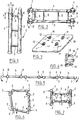
- la figure 1 est une vue en perspective d'un organe d'articulation selon l'invention,
- la figure 2 est une vue en perspective d'un panneau selon l'invention,
- la figure 3 est une vue en perspective d'un plateau selon l'invention en position retournée,
- la figure 4 est une vue de dessus d'une des bagues du plateau de la figure 3,
- la figure 5 est une représentation schématique de dessus de l'assemblage de panneaux selon une première phase de montage,
- la figure 6 est une vue analogue à celle de la figure 5 dans une seconde phase de montage, et
- la figure 7 est une vue analogue à celle de la figure 6 en position finale d'un assemblage de panneaux selon l'invention servant de piètement pour une table.
- FIG. 1 is a perspective view of a hinge member according to the invention,
- FIG. 2 is a perspective view of a panel according to the invention,
- FIG. 3 is a perspective view of a tray according to the invention in the inverted position,
- FIG. 4 is a top view of one of the rings of the tray of FIG. 3,
- FIG. 5 is a schematic representation from above of the assembly of panels according to a first assembly phase,
- FIG. 6 is a view similar to that of FIG. 5 in a second mounting phase, and
- Figure 7 is a view similar to that of Figure 6 in the final position of an assembly of panels according to the invention serving as a base for a table.
En référence aux figures, l'invention va maintenant être décrite dans son mode relatif à la réalisation d'une table.With reference to the figures, the invention will now be described in its mode relating to the production of a table.
Chaque organe d'articulation généralement désigné en 1, est formé de deux poteaux cylindriques 2 s'étendant parallèlement l'un à l'autre et rigidement reliés entre eux par des entretoises cylindriques 3 qui maintiennent les poteaux 2 espacés l'un de l'autre. Au voisinage de leur extrémité supérieure, les poteaux 2 sont équipés d'un anneau de positionnement 4 qui est maintenu en place par l'une des entretoises 3.Each articulation member generally designated at 1, is formed by two
En référence à la figure 2, les panneaux selon le mode de réalisation préféré de l'invention, comportent deux barreaux 5 reliés rigidement l'un à l'autre par des entretoises 6 qui les maintiennent espacés l'un de l'autre et parallèles l'un à l'autre. A chacune de leurs extrémités, les barreaux 5 portent des bagues élastiques 7 comportant chacune une ouverture 8 dirigée latéralement par rapport aux panneaux et ayant une largeur l légèrement inférieure à un diamètre d des poteaux 2. De préférence, les bagues 7 comportent sur leur côté extérieur une nervure de rigidification 9 qui laisse à la bague une élasticité suffisante pour permettre un encliquetage des bagues 7 sur les poteaux 2 tout en assurant un verrouillage approprié des bagues 7 une fois qu'elles sont en place. Pour réaliser un assemblage de panneaux selon l'invention, chaque panneau est tout d'abord associé à un ou deux organes d'articulation pour former une chaîne de panneaux comme illustré par la figure 5. Pour réaliser ce montage, les organes d'articulation 1 peuvent être disposés à plat sur le sol et les ouvertures 8 des bagues 7 sont mises en regard des poteaux 2 de sorte qu'un simple appui sur les panneaux permet par le poids du corps de réaliser un encliquetage des bagues 7 sur les poteaux 2.Referring to Figure 2, the panels according to the preferred embodiment of the invention comprise two
Lorsque les poteaux sont équipés d'anneaux de positionnement 4 comme illustré sur la figure 1, la hauteur h de ces anneaux de positionnement 4 est égale ou légèrement inférieure à l'écartement e entre les bords en regard de deux bagues 7 adjacentes de sorte que les bagues 7 peuvent être encliquetées sur les poteaux 2 de part et d'autre d'un anneau de positionnement 4. Après assemblage les panneaux restent ainsi positionnés de façon adjacente à l'extrémité supérieure des poteaux 2 lorsque l'assemblage des panneaux est disposé verticalement. Si l'on souhaite monter un panneau à une hauteur différente des autres on peut également encliqueter les bagues de part et d'autre d'une entretoise 3 qui joue alors le rôle de butée haute ou basse pour le panneau. Les ouvertures 8 des bagues 7 sont de préférence toutes montées selon la même orientation comme illustré par la figure 5.When the posts are equipped with
L'assemblage ainsi réalisé est ensuite refermé selon une boucle en associant le poteaux 2 qui est à une extrémité de la chaîne avec les bagues élastiques 7 qui sont à l'extrémité opposée de la chaîne. Ce mouvement est de préférence réalisé comme indiqué par les flèches sur la figure 5, de façon que les ouvertures 8 soient toutes tournées vers l'extérieur comme illustré sur la figure 6. L'assemblage a alors une forme quelconque et pour réaliser une boucle fermée, il suffit de présenter les bagues extrêmes en regard du poteau extrême 2 par l'intérieur de celui-ci, comme illustré par la figure 6 puis de faire pivoter le panneau comme illustré par la flèche en trait épais continu sur la figure 6 pour encliqueter les bagues 7 sur le poteau 2. Chacun des organes d'articulation 1 est alors pivoté autour d'un poteau 2 comme illustré par les flèches en trait pointillé épais sur la figure 6, de façon à ramener deux panneaux en regard à l'intérieur de l'espace compris entre les deux panneaux adjacents jusqu'à ce que les bagues 7 des panneaux intérieurs soient en butée contre les barreaux 5 des panneaux extérieurs comme illustré sur la figure 7.The assembly thus produced is then closed in a loop by associating the
Par ailleurs, pour la réalisation d'une table, on prévoit selon l'invention d'équiper le plateau 10 de la table avec des bagues élastiques 11 comportant chacune une ouverture 12 qui débouche sur un côté de la bague 11 perpendiculaire au plan du plateau 10. Comme illustré par la figure 4, les bagues élastiques 11 ont de préférence des bords latéraux 13 en forme d'hélices convergentes de façon à laisser l'accès à la partie de bague qui est en contact avec le plateau 10 et permettre ainsi la fixation des bagues 11 par des vis 14. De préférence les bagues 11 comportent également une nervure de rigidification 15.Furthermore, for the production of a table, provision is made according to the invention to equip the
Dans le mode de réalisation illustré, le plateau 10 est équipé de quatre bagues 11 disposées selon deux lignes parallèles qui sont espacées l'une de l'autre d'une distance d égale à celle des barreaux de fixation 5 lorsque les panneaux de l'assemblage sont disposés comme il a été décrit précédemment à propos de la figure 7. Pour l'assemblage de la table, le plateau est alors disposé sur l'extrémité supérieure des poteaux 2 avec les ouvertures 12 des bagues 11 tournées vers un barreau de fixation 5 puis le plateau est glissé latéralement jusqu'à encliquetage des quatre bagues 11 sur les barreaux de fixation 5. On peut également fixer tout d'abord deux bagues sur l'un des barreaux de fixation, les côtés de l'assemblage de panneaux étant disposés selon une orientation quelconque, puis déformer l'assemblage de panneaux pour amener le second barreau de fixation en regard des autres bagues 11 et réaliser l'encliquetage final. On remarquera que dans cette position les bagues 11 assurent un verrouillage de l'assemblage au panneau dans la position illustrée sur la figure 7 de sorte que les bagues 7 ne peuvent pas se dégager des poteaux 2 ce qui confère une grande rigidité au piètement. On remarquera également que les poteaux 2 sont disposés sensiblement selon des diagonales du rectangle de sorte qu'ils réalisent une gêne minimum à l'accès sous le plateau de la table.In the illustrated embodiment, the
Bien entendu l'invention n'est pas limitée au mode de réalisation décrit et on peut y apporter des variantes de réalisation sans sortir du cadre de l'invention tel que défini par les revendications.Of course, the invention is not limited to the embodiment described and it is possible to make variant embodiments without departing from the scope of the invention as defined by the claims.
En particulier, bien que l'invention ait été décrite pour une table dont le plateau est fixé horizontalement, on peut prévoir de fixer l'un des barreaux de fixation sur un panneau selon une hauteur réglable de façon à permettre une variation de l'inclinaison du plateau.In particular, although the invention has been described for a table whose table is fixed horizontally, provision can be made to fix one of the fixing bars on a panel at an adjustable height so as to allow a variation in the inclination of the plateau.
Bien que dans le mode de réalisation préféré illustré, les organes d'articulation soient formés de deux poteaux réunis par des entretoises, on peut réaliser des organes d'articulation comprenant un panneau plein dans lequel sont réalisées des encoches latérales équipées d'axes d'articulation verticaux.Although in the preferred embodiment illustrated, the articulation members are formed of two posts joined by spacers, articulation members can be produced comprising a solid panel in which are made lateral notches equipped with axes of vertical articulation.
Par ailleurs, bien que l'assemblage de panneau selon l'invention ait été décrit en relation avec un piètement de table, on peut réaliser également des assemblages de panneaux pour des utilisations très variées, par exemple pour la réalisation d'un parc, les panneaux ayant alors sensiblement la même hauteur que les organes d'articulation, ou pour la réalisation d'un lit.Furthermore, although the panel assembly according to the invention has been described in relation to a table base, it is also possible to assemble panel assemblies for very varied uses, for example for the production of a park, the panels then having substantially the same height as the articulation members, or for the production of a bed.
Bien que dans le mode de réalisation illustré il soit prévu deux bagues 7 à l'extrémité de chaque panneau et deux bagues 11 pour la liaison du plateau avec chaque barreau de fixation on peut réaliser l'invention avec un nombre quelconque de bagues, le nombre et la configuration des bagues étant adaptés à l'utilisation de l'assemblage de panneaux.Although in the illustrated embodiment there are provided two
Claims (8)
Applications Claiming Priority (2)
| Application Number | Priority Date | Filing Date | Title |
|---|---|---|---|
| FR9408167 | 1994-07-01 | ||
| FR9408167A FR2721979B1 (en) | 1994-07-01 | 1994-07-01 | PANEL ASSEMBLY AND TABLE COMPRISING A BASE FORMED BY THIS PANEL ASSEMBLY |
Publications (1)
| Publication Number | Publication Date |
|---|---|
| EP0694268A1 true EP0694268A1 (en) | 1996-01-31 |
Family
ID=9464921
Family Applications (1)
| Application Number | Title | Priority Date | Filing Date |
|---|---|---|---|
| EP95401580A Withdrawn EP0694268A1 (en) | 1994-07-01 | 1995-06-30 | Panel assembly and table with a frame made of this panel assembly |
Country Status (2)
| Country | Link |
|---|---|
| EP (1) | EP0694268A1 (en) |
| FR (1) | FR2721979B1 (en) |
Cited By (2)
| Publication number | Priority date | Publication date | Assignee | Title |
|---|---|---|---|---|
| FR2805138A1 (en) | 2000-02-22 | 2001-08-24 | Ange Prados | Articulated support assembly comprises six support rods coupled to each other by pivots |
| WO2018229725A1 (en) * | 2017-06-16 | 2018-12-20 | Val Di Pejo Servizi Di Giovanninetti Agnese & C. S.A.S. | Support frame |
Families Citing this family (1)
| Publication number | Priority date | Publication date | Assignee | Title |
|---|---|---|---|---|
| CN113040523B (en) * | 2021-03-17 | 2022-04-01 | 章小波 | Engineering cost building budget rehearsal device |
Citations (4)
| Publication number | Priority date | Publication date | Assignee | Title |
|---|---|---|---|---|
| GB1076302A (en) * | 1965-04-28 | 1967-07-19 | Dick Arne Fredrik Flodell | Collapsible table |
| FR2087577A5 (en) * | 1970-05-25 | 1971-12-31 | Bourgeois Emmanuel | |
| US4112855A (en) * | 1977-09-29 | 1978-09-12 | Scott Paper Company | Foldable furniture unit |
| FR2652135A1 (en) * | 1989-09-20 | 1991-03-22 | Rd Plastiques | Panel including a hook system for making up any square or rectangular container |
-
1994
- 1994-07-01 FR FR9408167A patent/FR2721979B1/en not_active Expired - Fee Related
-
1995
- 1995-06-30 EP EP95401580A patent/EP0694268A1/en not_active Withdrawn
Patent Citations (4)
| Publication number | Priority date | Publication date | Assignee | Title |
|---|---|---|---|---|
| GB1076302A (en) * | 1965-04-28 | 1967-07-19 | Dick Arne Fredrik Flodell | Collapsible table |
| FR2087577A5 (en) * | 1970-05-25 | 1971-12-31 | Bourgeois Emmanuel | |
| US4112855A (en) * | 1977-09-29 | 1978-09-12 | Scott Paper Company | Foldable furniture unit |
| FR2652135A1 (en) * | 1989-09-20 | 1991-03-22 | Rd Plastiques | Panel including a hook system for making up any square or rectangular container |
Cited By (3)
| Publication number | Priority date | Publication date | Assignee | Title |
|---|---|---|---|---|
| FR2805138A1 (en) | 2000-02-22 | 2001-08-24 | Ange Prados | Articulated support assembly comprises six support rods coupled to each other by pivots |
| EP1132023A1 (en) | 2000-02-22 | 2001-09-12 | Ange Prados | Articulated assembly device |
| WO2018229725A1 (en) * | 2017-06-16 | 2018-12-20 | Val Di Pejo Servizi Di Giovanninetti Agnese & C. S.A.S. | Support frame |
Also Published As
| Publication number | Publication date |
|---|---|
| FR2721979A1 (en) | 1996-01-05 |
| FR2721979B1 (en) | 1996-08-02 |
Similar Documents
| Publication | Publication Date | Title |
|---|---|---|
| EP0577496B1 (en) | Compact collapsible push chair for children | |
| EP0250287B1 (en) | Removable, closing and opening covering structure | |
| EP0725464B1 (en) | Base for an electric cabinet or similar and a cabinet equipped with such a base | |
| FR2827555A1 (en) | Seat track assembly for vehicle, has connector pivotally connected to second seat track and handle to engages with multiple pins and move each pin from engaged to disengaged position | |
| EP0694268A1 (en) | Panel assembly and table with a frame made of this panel assembly | |
| FR2615377A1 (en) | LIFTING RIG FOR A HORIZONTAL FRAME | |
| FR2589698A1 (en) | TABLE WITH EXTENSIONS | |
| EP0261008B1 (en) | Removable hinge, especially for a fishermen's seat box | |
| FR2769815A1 (en) | Folding cot with folding frame holding cradle | |
| EP0536024B1 (en) | Collapsible display pannel having tubular frame and pivoting holding box | |
| EP0347388A1 (en) | Modular variable alignment barrier for creating a protective enclosure | |
| EP0307336B1 (en) | Filing unit for documents or the like and a filing assembly with inclined sections consisting of many of said units | |
| FR2706408A1 (en) | Stroller type vehicle. | |
| FR2758963A1 (en) | COOKING GRID WITH ARTICULATED PANELS | |
| WO1994001631A1 (en) | Expandable and collapsible structure particularly for forming a stall | |
| FR2664140A1 (en) | Folding table with integral seats | |
| EP0620986A1 (en) | Foldable fastener for a bracelet | |
| FR2492640A1 (en) | Vertical hinge for folding table - has four plates held together by three pins with ends joined by removable pin | |
| FR2754877A1 (en) | Self-stabilising table base frame | |
| CH664680A5 (en) | ROTATING DISPLAY. | |
| FR2586574A1 (en) | Underframe device for a table top in two pieces which can be folded up, particularly for a ping-pong table | |
| FR2762977A1 (en) | Table with extensions supported by folding legs | |
| FR2721808A1 (en) | Table top fixed to pivoting legs with two panels | |
| FR2604075A1 (en) | Folding chair with pivoting backrest | |
| EP1132023B1 (en) | Articulated assembly device |
Legal Events
| Date | Code | Title | Description |
|---|---|---|---|
| PUAI | Public reference made under article 153(3) epc to a published international application that has entered the european phase |
Free format text: ORIGINAL CODE: 0009012 |
|
| 17P | Request for examination filed |
Effective date: 19950703 |
|
| AK | Designated contracting states |
Kind code of ref document: A1 Designated state(s): BE CH DE ES GB IT LI |
|
| 17Q | First examination report despatched |
Effective date: 19970407 |
|
| GRAG | Despatch of communication of intention to grant |
Free format text: ORIGINAL CODE: EPIDOS AGRA |
|
| STAA | Information on the status of an ep patent application or granted ep patent |
Free format text: STATUS: THE APPLICATION HAS BEEN WITHDRAWN |
|
| 18W | Application withdrawn |
Withdrawal date: 19971231 |