EP0693382A1 - Printer having a movable print head - Google Patents
Printer having a movable print head Download PDFInfo
- Publication number
- EP0693382A1 EP0693382A1 EP94202084A EP94202084A EP0693382A1 EP 0693382 A1 EP0693382 A1 EP 0693382A1 EP 94202084 A EP94202084 A EP 94202084A EP 94202084 A EP94202084 A EP 94202084A EP 0693382 A1 EP0693382 A1 EP 0693382A1
- Authority
- EP
- European Patent Office
- Prior art keywords
- print head
- carriage
- printing
- printer according
- relative
- Prior art date
- Legal status (The legal status is an assumption and is not a legal conclusion. Google has not performed a legal analysis and makes no representation as to the accuracy of the status listed.)
- Granted
Links
- 239000003550 marker Substances 0.000 claims description 17
- 238000006073 displacement reaction Methods 0.000 claims description 10
- 230000004044 response Effects 0.000 claims description 6
- 239000000919 ceramic Substances 0.000 claims description 4
- 238000010276 construction Methods 0.000 claims 2
- 230000008901 benefit Effects 0.000 description 5
- 230000009471 action Effects 0.000 description 2
- 239000011159 matrix material Substances 0.000 description 2
- 239000002184 metal Substances 0.000 description 2
- 230000001133 acceleration Effects 0.000 description 1
- 238000006243 chemical reaction Methods 0.000 description 1
- 239000003086 colorant Substances 0.000 description 1
- 238000013016 damping Methods 0.000 description 1
- 238000010586 diagram Methods 0.000 description 1
- 238000010438 heat treatment Methods 0.000 description 1
- 230000004048 modification Effects 0.000 description 1
- 238000012986 modification Methods 0.000 description 1
- 230000009897 systematic effect Effects 0.000 description 1
Images

Classifications
-
- B—PERFORMING OPERATIONS; TRANSPORTING
- B41—PRINTING; LINING MACHINES; TYPEWRITERS; STAMPS
- B41J—TYPEWRITERS; SELECTIVE PRINTING MECHANISMS, i.e. MECHANISMS PRINTING OTHERWISE THAN FROM A FORME; CORRECTION OF TYPOGRAPHICAL ERRORS
- B41J2/00—Typewriters or selective printing mechanisms characterised by the printing or marking process for which they are designed
- B41J2/005—Typewriters or selective printing mechanisms characterised by the printing or marking process for which they are designed characterised by bringing liquid or particles selectively into contact with a printing material
- B41J2/01—Ink jet
- B41J2/135—Nozzles
- B41J2/145—Arrangement thereof
- B41J2/155—Arrangement thereof for line printing
-
- B—PERFORMING OPERATIONS; TRANSPORTING
- B41—PRINTING; LINING MACHINES; TYPEWRITERS; STAMPS
- B41J—TYPEWRITERS; SELECTIVE PRINTING MECHANISMS, i.e. MECHANISMS PRINTING OTHERWISE THAN FROM A FORME; CORRECTION OF TYPOGRAPHICAL ERRORS
- B41J25/00—Actions or mechanisms not otherwise provided for
- B41J25/001—Mechanisms for bodily moving print heads or carriages parallel to the paper surface
- B41J25/005—Mechanisms for bodily moving print heads or carriages parallel to the paper surface for serial printing movements superimposed to character- or line-spacing movements
-
- B—PERFORMING OPERATIONS; TRANSPORTING
- B41—PRINTING; LINING MACHINES; TYPEWRITERS; STAMPS
- B41J—TYPEWRITERS; SELECTIVE PRINTING MECHANISMS, i.e. MECHANISMS PRINTING OTHERWISE THAN FROM A FORME; CORRECTION OF TYPOGRAPHICAL ERRORS
- B41J25/00—Actions or mechanisms not otherwise provided for
- B41J25/34—Bodily-changeable print heads or carriages
-
- B—PERFORMING OPERATIONS; TRANSPORTING
- B41—PRINTING; LINING MACHINES; TYPEWRITERS; STAMPS
- B41J—TYPEWRITERS; SELECTIVE PRINTING MECHANISMS, i.e. MECHANISMS PRINTING OTHERWISE THAN FROM A FORME; CORRECTION OF TYPOGRAPHICAL ERRORS
- B41J29/00—Details of, or accessories for, typewriters or selective printing mechanisms not otherwise provided for
- B41J29/42—Scales and indicators, e.g. for determining side margins
-
- B—PERFORMING OPERATIONS; TRANSPORTING
- B41—PRINTING; LINING MACHINES; TYPEWRITERS; STAMPS
- B41J—TYPEWRITERS; SELECTIVE PRINTING MECHANISMS, i.e. MECHANISMS PRINTING OTHERWISE THAN FROM A FORME; CORRECTION OF TYPOGRAPHICAL ERRORS
- B41J2202/00—Embodiments of or processes related to ink-jet or thermal heads
- B41J2202/01—Embodiments of or processes related to ink-jet heads
- B41J2202/14—Mounting head into the printer
Definitions
- the present invention relates to a printer, such as an ink jet printer, comprising a print head mounted on a carriage and having at least one printing element for successively printing pixels onto a recording medium and means for moving said carriage and said recording medium relative to one another in a main scanning direction and a subscanning direction perpendicular to the main scanning direction.
- a printer such as an ink jet printer, comprising a print head mounted on a carriage and having at least one printing element for successively printing pixels onto a recording medium and means for moving said carriage and said recording medium relative to one another in a main scanning direction and a subscanning direction perpendicular to the main scanning direction.
- a printer according to the preamble has been disclosed in US-A-4 688 050.
- This known printer comprises a platen for advancing a recording medium, e.g. a sheet of paper, in a subscanning direction, and a carriage which is movable in a main scanning direction perpendicular to the subscanning direction.
- a print head which comprises a linear array of printing elements, e.g. heating elements in case of a thermal printer or nozzles in case of an ink jet printer, which are arranged in the subscanning direction, so that a plurality of pixel-wide image lines can be printed during each scanning movement of the carriage.
- the print head of this known printer is equipped with a sensor for detecting a registration mark which has been printed on the margin of the paper during a previous scan by means of a special printing element provided on the print head. Further, the number of printing elements in the array is larger than the number of print lines produced per main scan.
- the sensor When the sensor detects that the registration mark on the paper is properly adjusted in relation to the print head, at least one print element at each end of the array is kept inoperative, and only the central group of printing elements is used for actually printing the image information. If, however, the sensor detects that the paper has been advanced too much or too little, then the printing information is diverted to another group of printing elements which is offset from the original group by one or more pixels in an appropriate direction so as to compensate for the registration error.
- the effective positions of the printing elements are virtually shifted in the subscanning direction whereas the print head itself remains stationary relative to the printing paper in the subscanning direction.
- This known printer has the drawback that the effective positions of the printing elements can only be shifted in increments of the distance between two printing elements, so that the registration accuracy is limited to plus or minus half that distancel. As a result, the quality of the printed image may still be poor.
- printers which are disclosed, for example in JP-A-55-113572 and JP-A-63-285068, use registration marks and sensors for directly controlling the advance of the recording medium.
- it is intended to increase the resolution of the printer to for example 400 dpi or even 600 dpi, it becomes increasingly difficult to control the advance of the recording medium with sufficient accuracy, and expensive equipment is required for this purpose.
- the printer according to the preamble is equipped with means for dynamically, i.e. during the printing operation, displacing the printhead, relative to the carriage, in a scanning direction.
- a (preferably electromechanical) actuator is used for displacing the print head relative to the carriage, so as to finely adjust the print head position.
- the invention has the advantage that the registration accuracy can be enhanced far beyond the distance between two printing elements, so that the quality of the printed image is significantly improved.
- the invention has the advantage that the mass of inertia of the print head which has to be moved during fine adjustment is much smaller than the mass of inertia of the mechanical members, e.g. a platen, which are used for advancing the recording medium.
- the electromechanical actuator used according to the invention can be comparatively small and inexpensive, and, in addition, the time required for registration control can be reduced so that the overall printing speed is enhanced.
- the displacement of the print head relative to the carriage is controlled in response to the signal of a sensor which is arranged on the print head for detecting a registration mark on the printing paper.
- the direction of displacement of the print head relative to the carriage is perpendicular to the direction of movement of the carriage itself, so that the mounting of the print head permitting the displacement in the subscanning direction will not be affected by the forces of inertia resulting from the back and forth movement of the carriage.
- the print head can be mounted stably without incurring the risk of undesired vibrations.
- the invention is not limited to printers of this type.
- the printer could also be of a type in which the recording medium is fixed onto a rotating drum for producing the relative movement of the recording medium and the print head in the main scanning direction, and the carriage carrying the print head is advanced in small increments in the subscanning direction.
- the carriage is used for coarsely adjusting the position of the print head in the subscanning direction
- the electromechanical actuator is used for fine-adjustment in the same direction.
- the forces of inertia caused by the acceleration and deceleration of the carriage will be less important because the speed of advance of the carriage in the subscanning direction can be made comparatively small without significantly increasing the overall printing speed.
- the electromechanical actuator can be used for actively damping vibrations which may be caused by the deceleration of the carriage.
- Another object of the invention is to provide a printer which comprises an array of a plurality of printing elements on a common print head and which is provided with a simple structure for interlaced printing so as to achieve a printing resolution which is higher than the pitch of the printing elements in the array.
- This object is achieved in that the actuator discussed above is used for displacing the print head in the subscanning direction by an increment which amounts to the pitch of the printing elements divided by an integral number n, so that n-fold interlacing is achieved by repeating n scans in the main scanning direction with successively increased displacement of the print head, without changing the relative position of the carriage and the recording medium in the subscanning direction.
- the printer it is possible to achieve a high resolution of for example 400 dpi, even if the dimensions of the printing elements and the mounting structures thereof make it difficult to reduce the spacings between adjacent printing elements to the size of one pixel.
- the invention takes advantage of the fact that the actuator permits to adjust the position of the print head quickly and accurately, so that interlacing can be performed with high accuracy and with high speed, because it is not necessary to advance the recording medium after each main scan.
- a sensor for detecting registration marks on the recording medium may be used for registering the paper feed motion after the completion of n interlaced scans.
- piezoelectric actuators are used, because they provide a quick response and permit to stably support the print head and also have a substantially linear voltage/displacement characteristic which facilitates the electronic control.
- ceramic multilayer actuators are particularly preferred, because they offer a large range of displacements and require only a relatively low control voltage.
- a parallelogram linkage with link bars having flexible hinge portions at their opposite ends.
- the piezoelectric actuator may be arranged to act upon one or both of the longitudinal ends of the print head or may be arranged to act upon the link bars of the parallelogram so that a greater displacement can be achieved by lever action of the link bars.
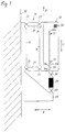
- an ink jet printer comprises a carriage 10 which is movable back and forth in a main scanning direction indicated by arrows A.
- a recording medium (not shown in Fig. 1) which may for example be formed by a sheet of paper is fed in a subscanning direction which is indicated by arrow B and is perpendicular to the main scanning direction A.
- a print head 12 is mounted to the carriage 10 by means of a parallelogram linkage 14, so that it is rigidly supported on the carriage in the main scanning direction A but is displaceable in opposite directions parallel with the subscanning direction B, as is indicated by arrows C.
- the parallelogram linkage 14 is formed of a one-piece metal member and comprises a base portion 16 fixed to the carriage 10, a bracket portion 18 to which the print head 12 is secured, and two link bars 20 connected to the base portion 16 and the bracket portion 18, respectively, through hinge portions 22.
- Each hinge portion is formed by a relatively thin and hence flexible web which is bounded by approximately circular or semi-circular recesses formed in the metal member.
- the parallelogram linkage 14 is formed integrally with a support 26 for a ceramic multilayer actuator (CMA) 28 arranged for controlling the displacement of the print head 12 in the directions C.
- CMA ceramic multilayer actuator
- a CMA is formed by a plurality of layers of piezoelectric ceramics alternatingly laminated with electrodes. By applying a voltage to the electrodes, the CMA 28 is caused to expand or shrink in the directions C, depending on the polarity of the voltage applied.
- the CMA 28 is connected to the support 26 and to the print head 12 through hinge portions 30 which have the same configuration as the hinge portions 22 discussed above.
- the print head 12 is provided with a number of nozzles 32, 32a, 32b, 34, 34a and 34b which are arranged with equal spacings in a linear array or column extending in the subscanning direction B.
- the nozzles 32, 32a and 32b serve as printing elements for printing individual pixels on the sheet of paper by ejecting ink droplets onto the paper in accordance with the image information supplied to the print head.
- the nozzles 34, 34a and 34b serve as marker nozzles for printing a registration mark onto the margin portion of the paper.
- the print head 12 is further provided with an electro-optical sensor 36 which is positioned near the end of the row of nozzles opposite to the marker nozzles.
- an electro-optical sensor 36 which is positioned near the end of the row of nozzles opposite to the marker nozzles.
- a control unit 38 for the printer comprises a print head control block 40, a paper feed control block 42, a carriage control block 44 and a piezo control block 46.
- the control unit may be formed by a microcomputer programmed to perform all the functions symbolized by the four control blocks 40 to 46.
- the paper feed control block 42 controls the function of the paper feed system which may for example comprise a platen 48 for advancing a sheet of paper 50 (recording medium) in the subscanning direction B.
- the carriage control block 44 controls the function of a carriage drive system 52 for moving the carriage 10 in the main scanning direction A.
- the piezo control block 46 receives a signal from the sensor 36 and controls the actuator 28 in accordance therewith.
- the print head control block 40 cooperates with the piezo control block 46 and selects the printing nozzles 32, 32a, 32b and actuates the marker nozzles 34, 34a, 34b in accordance with the signal from the sensor 36, as will be explained below, and supplies control signals to the print head 12 in accordance with the image information to be printed.
- the registration mark has the form of a dot or a faint line segment extending in the main scanning direction A.
- the sensor 36 is preferably formed by a matrix array of light sensitive elements (e.g. an area CCD) and is capable of detecting the position of the registration mark with a resolution which is significantly higher than the printing resolution of the printer.
- a registration mark in line form is used, a one-dimensial sensor may be used.
- the sensor 36 will detect the registration mark at a predetermined target position, thus assuring that the new lines to be printed with the printing nozzles will correctly adjoin the lines that have been printed during the previous stroke of the carriage 10. If, however, the paper has not been advanced by the correct amount, due to paper slippage or inaccuracies in the paper feed system of the printer, then the sensor 36 will detect a deviation of the registration mark from the target position, and in reaction the piezo control 46 will supply an appropriate voltage to the CMA 28 in order to precisely adjust the print head 12 to the registration mark before the next stroke of the carriage 10 is started.
- a new registration mark is printed in the margin portion before the printing nozzles reach the printable area of the paper. Accordingly, the new registration mark represents the adjusted position of the print head.
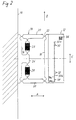
- the modified embodiment shown in Fig. 2 differs from the arrangement according to Fig. 1 in that the mount 26 is provided inside of the parallelogram linkage 14 and two piezoelectric actuators (CMAs) 28 are connected between the mount 26 and each of the link bars 20 in the vicinity of the base portion 16.
- CMAs piezoelectric actuators
- the printing nozzles comprise twenty regular printing nozzles 32 and two auxiliary printing nozzles 32a, 32b provided at both ends of the column of regular printing nozzles.
- the regular printing nozzles 32 are used, so that twenty image lines are printed during one stroke of the carriage 10.
- the auxiliary nozzle 32a is used for printing, and one of the regular printing nozzles 32 at the opposite end of the row (adjacent the auxiliary printing nozzle 32b) is kept inoperative.
- the registration mark is not printed with the nozzle 34 but with the nozzle 34a so that the correct positional relationship between the registration mark and the printed image lines is maintained.
- the auxiliary printing nozzle 32b and the nineteen regular printing nozzles 32 adjacent thereto are used for printing the image, and the marker nozzle 34b is used for printing the registration mark.
- the marker nozzles may be structurally identical with the printing nozzles. If it is desired to avoid the visible registration marks on the margin of the printed image, it is possible to supply the marker nozzles with a specific ink which is practically imperceptible by the human eye but can be detected by the sensor 36. On the other hand, when the marker nozzles are supplied with the same ink as the printing nozzles, it is determined merely by the control system whether a specific nozzle has the function of a printing nozzle or a marker nozzle, so that the flexibility of the system is increased.
- the number of image lines printed in one stroke of the carriage may also be varied. If, for example, the paper feed system includes a systematic error so that the registration errors produced in each scan cycle accumulate and the adjustment range provided by the auxiliary nozzles and actuators 28 tends to become exhausted, the paper feed error can be compensated by performing one or more scan cycles with a reduced or increased number of image lines and with appropriate selection of the marker nozzle. In this way, the printer as a whole becomes very robust against paper feed errors, so that a simple and inexpensive paper feed system may be used.
- the spacing between adjacent image lines cannot be reduced below a certain limit which depends on the outer dimensions of the individual nozzles (e.g. about 0.5 mm). It is however possible to achieve a higher resolution by using an array in which the nozzles are staggered in a plurality of columns. If, for example, an array with four columns is used, it should be possible to achieve a one-stroke resolution of 8 lines/mm, so that the spacing between the lines will be as small as 125 mm.
- the image lines must be only 63.5 mm apart. This can be achieved by interlacing the lines printed in subsequent strokes.
- the printer according to the invention is particularly useful for such an interlaced printing mode, as will be explained below.
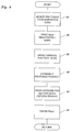
- Fig. 4 is a flow chart showing the control operations performed by the control unit 38 (Fig. 3) in the interlacing mode during one complete scan cycle of the carriage 10.
- step 54 the print head 12 is adjusted in accordance with the registration mark as has been described above.
- step 56 the carriage 10 starts to move, and one of the marker nozzles is actuated for printing the new registration mark.
- step 58 the carriage 10 performs a stroke from left to right in Figs. 1, 2 and 3 to print a number of image lines with the selected printing nozzles. It is assumed here that the pitch of the printing nozzles and hence the distance of the lines printed during this stroke is twice as large as the size of one pixel of the printed image, so that the image lines are separated by gaps with a width of one pixel.
- step 60 the actuator 28 is controlled to shift the position of the print head 12 by a predetermined increment in the subscanning direction B.
- This increment corresponds to one pixel, i.e. one half of the pitch of the nozzles. Since the piezoelectric actuator 28 has a linear response characteristic, this increment can be achieved by increasing the voltage applied to the actuator by a fixed amount. Thus, the sensor 36 is not needed for controlling this movement of the print head.
- step 62 the carriage 10 performs its return stroke to the initial position, and the print head is supplied with the image information for the lines which are interlaced with the lines printed during the forward stroke.
- step 64 the paper is advanced by the width of the image strip which has been printed in this cycle, and then the program returns to START to begin with a new scan cycle.
- the relative movement between the recording medium and the carriage may be achieved in any suitable manner, e.g. by moving the recording medium on a conveyor belt or the like or by holding the recording medium stationary and moving the carriage in two dimensions.
- the invention is not limited to ink jet printers but may also be applied to other scanning-type printers such as thermal printers, matrix printers and the like. Further, the invention is of course applicable also to colour printers.
- the printing elements for the different colours may then be provided on a common print head or on separate print heads which can be adjusted individually. In the latter case, it is also possible to use the actuators associated with the different print heads for controlling the colour registration electronically.
- a sensor which quantitatively detects the position of the registration mark with high resolution it is possible to use a sensor which can only detect whether or not the registration mark is present at the target position or at one of a plurality of target positions spaced apart by the pitch of the printing elements. Adjustment of the print head by means of the actuator is then performed in a feedback loop. If the actuator is used only for interlacing, the sensor and the marker nozzles may be omitted completely.
- the sensor signal relating to the print head position relative to the registration mark may additionally be used for synchronizing the main scan, so that successive scan lines can easily be aligned horizontally as well.
Landscapes
- Ink Jet (AREA)
- Character Spaces And Line Spaces In Printers (AREA)
- Dot-Matrix Printers And Others (AREA)
- Impact Printers (AREA)
- Common Mechanisms (AREA)
- Particle Formation And Scattering Control In Inkjet Printers (AREA)
Abstract
Description
- The present invention relates to a printer, such as an ink jet printer, comprising a print head mounted on a carriage and having at least one printing element for successively printing pixels onto a recording medium and means for moving said carriage and said recording medium relative to one another in a main scanning direction and a subscanning direction perpendicular to the main scanning direction.
- A printer according to the preamble has been disclosed in US-A-4 688 050. This known printer comprises a platen for advancing a recording medium, e.g. a sheet of paper, in a subscanning direction, and a carriage which is movable in a main scanning direction perpendicular to the subscanning direction. On the carriage, there is mounted a print head which comprises a linear array of printing elements, e.g. heating elements in case of a thermal printer or nozzles in case of an ink jet printer, which are arranged in the subscanning direction, so that a plurality of pixel-wide image lines can be printed during each scanning movement of the carriage.
- If the advance of paper in the subscanning direction is not controlled with high accuracy, white or dark streaks may be produced on the printed image, because either a gap or a slight overlap may occur between adjacent lines. In order to alleviate this problem, the print head of this known printer is equipped with a sensor for detecting a registration mark which has been printed on the margin of the paper during a previous scan by means of a special printing element provided on the print head. Further, the number of printing elements in the array is larger than the number of print lines produced per main scan.
- When the sensor detects that the registration mark on the paper is properly adjusted in relation to the print head, at least one print element at each end of the array is kept inoperative, and only the central group of printing elements is used for actually printing the image information. If, however, the sensor detects that the paper has been advanced too much or too little, then the printing information is diverted to another group of printing elements which is offset from the original group by one or more pixels in an appropriate direction so as to compensate for the registration error. Thus, the effective positions of the printing elements are virtually shifted in the subscanning direction whereas the print head itself remains stationary relative to the printing paper in the subscanning direction. This known printer has the drawback that the effective positions of the printing elements can only be shifted in increments of the distance between two printing elements, so that the registration accuracy is limited to plus or minus half that distancel. As a result, the quality of the printed image may still be poor.
- Many other printers which are disclosed, for example in JP-A-55-113572 and JP-A-63-285068, use registration marks and sensors for directly controlling the advance of the recording medium. However, if it is intended to increase the resolution of the printer to for example 400 dpi or even 600 dpi, it becomes increasingly difficult to control the advance of the recording medium with sufficient accuracy, and expensive equipment is required for this purpose.
- It is a first object of the invention to provide a printer which is structurally simple and can nevertheless achieve a high accuracy in registration between the printing elements and the lines already printed on the recording medium.
- This object is achieved in that the printer according to the preamble is equipped with means for dynamically, i.e. during the printing operation, displacing the printhead, relative to the carriage, in a scanning direction.
- According to the invention, a (preferably electromechanical) actuator is used for displacing the print head relative to the carriage, so as to finely adjust the print head position.
- In comparison to the prior art disclosed in US-A-4 688 050, the invention has the advantage that the registration accuracy can be enhanced far beyond the distance between two printing elements, so that the quality of the printed image is significantly improved.
- In comparison to conventional printers in which the registration control is exclusively performed by controlling the advance of the recording medium, the invention has the advantage that the mass of inertia of the print head which has to be moved during fine adjustment is much smaller than the mass of inertia of the mechanical members, e.g. a platen, which are used for advancing the recording medium. As a consequence, the electromechanical actuator used according to the invention can be comparatively small and inexpensive, and, in addition, the time required for registration control can be reduced so that the overall printing speed is enhanced.
- According to a further embodiment of the invention, the displacement of the print head relative to the carriage is controlled in response to the signal of a sensor which is arranged on the print head for detecting a registration mark on the printing paper.
- In printers of the type discussed above, in which the carriage is moved back and forth in the main scanning direction over the whole width of the recording medium, the direction of displacement of the print head relative to the carriage is perpendicular to the direction of movement of the carriage itself, so that the mounting of the print head permitting the displacement in the subscanning direction will not be affected by the forces of inertia resulting from the back and forth movement of the carriage. Thus, the print head can be mounted stably without incurring the risk of undesired vibrations.
- However, the invention is not limited to printers of this type. For example, the printer could also be of a type in which the recording medium is fixed onto a rotating drum for producing the relative movement of the recording medium and the print head in the main scanning direction, and the carriage carrying the print head is advanced in small increments in the subscanning direction. Here, the carriage is used for coarsely adjusting the position of the print head in the subscanning direction, and the electromechanical actuator is used for fine-adjustment in the same direction. In this case, the forces of inertia caused by the acceleration and deceleration of the carriage will be less important because the speed of advance of the carriage in the subscanning direction can be made comparatively small without significantly increasing the overall printing speed. In addition, the electromechanical actuator can be used for actively damping vibrations which may be caused by the deceleration of the carriage.
- Another object of the invention is to provide a printer which comprises an array of a plurality of printing elements on a common print head and which is provided with a simple structure for interlaced printing so as to achieve a printing resolution which is higher than the pitch of the printing elements in the array.
- This object is achieved in that the actuator discussed above is used for displacing the print head in the subscanning direction by an increment which amounts to the pitch of the printing elements divided by an integral number n, so that n-fold interlacing is achieved by repeating n scans in the main scanning direction with successively increased displacement of the print head, without changing the relative position of the carriage and the recording medium in the subscanning direction.
- With this printer, it is possible to achieve a high resolution of for example 400 dpi, even if the dimensions of the printing elements and the mounting structures thereof make it difficult to reduce the spacings between adjacent printing elements to the size of one pixel. The invention takes advantage of the fact that the actuator permits to adjust the position of the print head quickly and accurately, so that interlacing can be performed with high accuracy and with high speed, because it is not necessary to advance the recording medium after each main scan.
- In the interlacing mode, a sensor for detecting registration marks on the recording medium may be used for registering the paper feed motion after the completion of n interlaced scans.
- As an actuator, all kinds of known electromechanical devices can be used, including electromagnetic devices, magnetostrictive devices, pneumatic or hydraulic devices combined with electric pressure control means, e.g. hybrid control systems including fluidic elements, and the like. Preferably, however, piezoelectric actuators are used, because they provide a quick response and permit to stably support the print head and also have a substantially linear voltage/displacement characteristic which facilitates the electronic control. Among the piezoelectric actuators, ceramic multilayer actuators (CMAs) are particularly preferred, because they offer a large range of displacements and require only a relatively low control voltage.
- For displaceably mounting the print head on the carriage, it is preferable to use a parallelogram linkage with link bars having flexible hinge portions at their opposite ends. The piezoelectric actuator may be arranged to act upon one or both of the longitudinal ends of the print head or may be arranged to act upon the link bars of the parallelogram so that a greater displacement can be achieved by lever action of the link bars. Alternatively, it is also possible to use bending-type piezoelectric actuators as the link bars.
- Preferred embodiments of the invention will be described hereinbelow in conjunction with the accompanying drawings, in which:
- Fig. 1 is a schematic view of a print head assembly of a printer according to the invention;
- Fig. 2 shows a modification of the print head assembly;
- Fig. 3 is a block diagram of the printer; and
- Fig. 4 is a flow chart illustrating an interlacing printing mode.
- Referring to Fig. 1, an ink jet printer comprises a
carriage 10 which is movable back and forth in a main scanning direction indicated by arrows A. A recording medium (not shown in Fig. 1) which may for example be formed by a sheet of paper is fed in a subscanning direction which is indicated by arrow B and is perpendicular to the main scanning direction A. Aprint head 12 is mounted to thecarriage 10 by means of aparallelogram linkage 14, so that it is rigidly supported on the carriage in the main scanning direction A but is displaceable in opposite directions parallel with the subscanning direction B, as is indicated by arrows C. - The
parallelogram linkage 14 is formed of a one-piece metal member and comprises a base portion 16 fixed to thecarriage 10, abracket portion 18 to which theprint head 12 is secured, and twolink bars 20 connected to the base portion 16 and thebracket portion 18, respectively, throughhinge portions 22. Each hinge portion is formed by a relatively thin and hence flexible web which is bounded by approximately circular or semi-circular recesses formed in the metal member. - The
parallelogram linkage 14 is formed integrally with asupport 26 for a ceramic multilayer actuator (CMA) 28 arranged for controlling the displacement of theprint head 12 in the directions C. As is generally known in the art, a CMA is formed by a plurality of layers of piezoelectric ceramics alternatingly laminated with electrodes. By applying a voltage to the electrodes, theCMA 28 is caused to expand or shrink in the directions C, depending on the polarity of the voltage applied. TheCMA 28 is connected to thesupport 26 and to theprint head 12 throughhinge portions 30 which have the same configuration as thehinge portions 22 discussed above. - The
print head 12 is provided with a number ofnozzles nozzles nozzles 34, 34a and 34b serve as marker nozzles for printing a registration mark onto the margin portion of the paper. - The
print head 12 is further provided with an electro-optical sensor 36 which is positioned near the end of the row of nozzles opposite to the marker nozzles. When a registration mark has been printed onto the paper by means of one of the marker nozzles, e.g. thenozzle 34 and then, after thecarriage 10 has performed one back and forth stroke in the main scanning direction A, the paper is advanced in the subscanning direction B by an amount corresponding to the length of the row of printing nozzles, the registration mark can be detected by thesensor 36. - As is shown in Fig. 3, a
control unit 38 for the printer comprises a printhead control block 40, a paperfeed control block 42, acarriage control block 44 and apiezo control block 46. The control unit may be formed by a microcomputer programmed to perform all the functions symbolized by the fourcontrol blocks 40 to 46. - The paper
feed control block 42 controls the function of the paper feed system which may for example comprise aplaten 48 for advancing a sheet of paper 50 (recording medium) in the subscanning direction B. - The
carriage control block 44 controls the function of acarriage drive system 52 for moving thecarriage 10 in the main scanning direction A. Thepiezo control block 46 receives a signal from thesensor 36 and controls theactuator 28 in accordance therewith. - The print
head control block 40 cooperates with thepiezo control block 46 and selects theprinting nozzles marker nozzles 34, 34a, 34b in accordance with the signal from thesensor 36, as will be explained below, and supplies control signals to theprint head 12 in accordance with the image information to be printed. - The registration mark has the form of a dot or a faint line segment extending in the main scanning direction A. The
sensor 36 is preferably formed by a matrix array of light sensitive elements (e.g. an area CCD) and is capable of detecting the position of the registration mark with a resolution which is significantly higher than the printing resolution of the printer. In case a registration mark in line form is used, a one-dimensial sensor may be used. - If the paper has been advanced in the direction B exactly by the correct amount, the
sensor 36 will detect the registration mark at a predetermined target position, thus assuring that the new lines to be printed with the printing nozzles will correctly adjoin the lines that have been printed during the previous stroke of thecarriage 10. If, however, the paper has not been advanced by the correct amount, due to paper slippage or inaccuracies in the paper feed system of the printer, then thesensor 36 will detect a deviation of the registration mark from the target position, and in reaction thepiezo control 46 will supply an appropriate voltage to theCMA 28 in order to precisely adjust theprint head 12 to the registration mark before the next stroke of thecarriage 10 is started. - At the beginning of the next stroke, a new registration mark is printed in the margin portion before the printing nozzles reach the printable area of the paper. Accordingly, the new registration mark represents the adjusted position of the print head.
- The modified embodiment shown in Fig. 2 differs from the arrangement according to Fig. 1 in that the
mount 26 is provided inside of theparallelogram linkage 14 and two piezoelectric actuators (CMAs) 28 are connected between themount 26 and each of the link bars 20 in the vicinity of the base portion 16. In this embodiment, the displacement of the CMAs is magnified due to the lever action of the link bars 20 so that the position of theprint head 12 can be adjusted within a broader range. - In the embodiments described herein, the printing nozzles comprise twenty
regular printing nozzles 32 and twoauxiliary printing nozzles 32a, 32b provided at both ends of the column of regular printing nozzles. During normal operation, i.e. when the paper is advanced correctly, only theregular printing nozzles 32 are used, so that twenty image lines are printed during one stroke of thecarriage 10. - If, however, the paper has been advanced too far and the deviation of the registration mark from the target position amounts to more than half the spacing between two adjacent nozzles, then the
auxiliary nozzle 32a is used for printing, and one of theregular printing nozzles 32 at the opposite end of the row (adjacent the auxiliary printing nozzle 32b) is kept inoperative. In this case, the registration mark is not printed with thenozzle 34 but with the nozzle 34a so that the correct positional relationship between the registration mark and the printed image lines is maintained. - Similarly, if the paper has been advanced too little, the auxiliary printing nozzle 32b and the nineteen
regular printing nozzles 32 adjacent thereto are used for printing the image, and the marker nozzle 34b is used for printing the registration mark. - In this way, a coarse correction of registration errors is achieved by properly selecting the printing nozzles, and the
actuator 28 is needed only for an additional fine correction. This has the advantage that the range in which theprint head 12 can be displaced by the actuator oractuators 28 needs not be larger than ± 1/2 of the spacing between adjacent nozzles. - Of course, it is possible to provide more than one auxiliary nozzle at each end of the row of regular printing nozzles, so that even larger deviations can be corrected.
- It is also possible to use only a single marker nozzle and to store a different target position for the registration mark when one of the auxiliary nozzles has been used for printing. However, the use of a plurality of marker nozzles has the advantage that the
sensor 36 needs to have only a comparatively small sensitive range and can nevertheless safely detect the registration mark. - The marker nozzles may be structurally identical with the printing nozzles. If it is desired to avoid the visible registration marks on the margin of the printed image, it is possible to supply the marker nozzles with a specific ink which is practically imperceptible by the human eye but can be detected by the
sensor 36. On the other hand, when the marker nozzles are supplied with the same ink as the printing nozzles, it is determined merely by the control system whether a specific nozzle has the function of a printing nozzle or a marker nozzle, so that the flexibility of the system is increased. - In general, the number of image lines printed in one stroke of the carriage may also be varied. If, for example, the paper feed system includes a systematic error so that the registration errors produced in each scan cycle accumulate and the adjustment range provided by the auxiliary nozzles and
actuators 28 tends to become exhausted, the paper feed error can be compensated by performing one or more scan cycles with a reduced or increased number of image lines and with appropriate selection of the marker nozzle. In this way, the printer as a whole becomes very robust against paper feed errors, so that a simple and inexpensive paper feed system may be used. - In the shown embodiments, in which the array of printing nozzles and marker nozzles consists only of a single column, the spacing between adjacent image lines cannot be reduced below a certain limit which depends on the outer dimensions of the individual nozzles (e.g. about 0.5 mm). It is however possible to achieve a higher resolution by using an array in which the nozzles are staggered in a plurality of columns. If, for example, an array with four columns is used, it should be possible to achieve a one-stroke resolution of 8 lines/mm, so that the spacing between the lines will be as small as 125 mm.
- If the resolution is to be increased further to 400 dpi, the image lines must be only 63.5 mm apart. This can be achieved by interlacing the lines printed in subsequent strokes. The printer according to the invention is particularly useful for such an interlaced printing mode, as will be explained below.
- Fig. 4 is a flow chart showing the control operations performed by the control unit 38 (Fig. 3) in the interlacing mode during one complete scan cycle of the
carriage 10. - In
step 54, theprint head 12 is adjusted in accordance with the registration mark as has been described above. - In
step 56, thecarriage 10 starts to move, and one of the marker nozzles is actuated for printing the new registration mark. - In
step 58, thecarriage 10 performs a stroke from left to right in Figs. 1, 2 and 3 to print a number of image lines with the selected printing nozzles. It is assumed here that the pitch of the printing nozzles and hence the distance of the lines printed during this stroke is twice as large as the size of one pixel of the printed image, so that the image lines are separated by gaps with a width of one pixel. - When the carriage has completed its stroke, in
step 60, theactuator 28 is controlled to shift the position of theprint head 12 by a predetermined increment in the subscanning direction B. This increment corresponds to one pixel, i.e. one half of the pitch of the nozzles. Since thepiezoelectric actuator 28 has a linear response characteristic, this increment can be achieved by increasing the voltage applied to the actuator by a fixed amount. Thus, thesensor 36 is not needed for controlling this movement of the print head. - In
step 62, thecarriage 10 performs its return stroke to the initial position, and the print head is supplied with the image information for the lines which are interlaced with the lines printed during the forward stroke. - At the end of the return stroke, in
step 64, the paper is advanced by the width of the image strip which has been printed in this cycle, and then the program returns to START to begin with a new scan cycle. - While specific embodiments of the invention have been described above, it will occur to a person skilled in the art that these examples may be modified in various ways, without departing from the spirit and scope of the appended claims.
- For example, the relative movement between the recording medium and the carriage may be achieved in any suitable manner, e.g. by moving the recording medium on a conveyor belt or the like or by holding the recording medium stationary and moving the carriage in two dimensions.
- The invention is not limited to ink jet printers but may also be applied to other scanning-type printers such as thermal printers, matrix printers and the like. Further, the invention is of course applicable also to colour printers. The printing elements for the different colours may then be provided on a common print head or on separate print heads which can be adjusted individually. In the latter case, it is also possible to use the actuators associated with the different print heads for controlling the colour registration electronically.
- Instead of using a sensor which quantitatively detects the position of the registration mark with high resolution, it is possible to use a sensor which can only detect whether or not the registration mark is present at the target position or at one of a plurality of target positions spaced apart by the pitch of the printing elements. Adjustment of the print head by means of the actuator is then performed in a feedback loop. If the actuator is used only for interlacing, the sensor and the marker nozzles may be omitted completely.
- While, in the embodiment of Fig. 4, two groups of image lines are interlaced and the paper is advanced each time the carriage has performed two strokes (forward stroke and return stroke), it is also possible to advance the paper only after three or more strokes of the carriage, so that three or more groups of image lines are interlaced. If an odd number of groups of print lines are interlaced, registration marks may be provided on both margins of the printed image, so that the adjustment of the print head can be performed in both extreme positions of the carriage.
- The sensor signal relating to the print head position relative to the registration mark may additionally be used for synchronizing the main scan, so that successive scan lines can easily be aligned horizontally as well.
Claims (15)
- A printer comprising- a print head (12) mounted on a carriage (10) and having at least one printing element (32) for successively printing pixels onto a recording medium (50);- means (48, 52) for moving said carriage and said recording medium relative to one another in a main scanning direction (A) and a subscanning direction (B) perpendicular to the main scanning direction;characterized by
means for dynamically displacing said print head (12), relative to said carriage (10), in a scanning direction. - A printer according to claim 1, characterized in that the means for displacing the print head relative to the carriage include an electromechanical actuator (28).
- A printer according to claim 2, wherein said electromechanical actuator (28) is a piezoelectric actuator.
- A printer according to claim 1 or 2, also comprising- a sensor (36) arranged on said print head (12) for detecting a registration mark on said recording medium (50) and for providing a sensor signal indicative of the position of the print head relative to said registration mark;characterized by
control means (38) connected to said sensor (36) for controlling, in response to said sensor signal, said means for displacing the print head relative to the carriage and thereby adjusting the position of the print head relative to the registration mark. - A printer according to claim 4, wherein said print head (12) comprises a plurality of printing elements (32, 32a, 32b) arrayed in the subscanning direction (B), the number of printing elements being larger than the number of image lines printed during one stroke of the carriage (10) in the main scanning direction, and control means (40) are provided for selecting a group of adjacent printing elements in response to the sensor signal, such that the position of the selected printing elements is coarsely adjusted to the registration mark.
- A printer according to claim 4 or 5, wherein the print head (12) comprises at least one marker printing element (34, 34a, 34b) for printing the registration mark onto the recording medium.
- A printer according to claims 5 and 6, wherein the print head (12) has a plurality of marker printing elements (34, 34a, 34b) and the printing element actually used for printing the registration mark is selected in accordance with the group of printing elements selected for printing the image information.
- A printer according to claim 1 or 2, in which said print head (12) has a number m ≧ 2 of printing elements (32) arrayed in the subscanning direction with a predetermined pitch p, characterized by- control means (38) for controlling the carriage (10), the electromechanical actuator (28) and the print head (12) such that the carriage performs a number n ≧ 2 of scans in main scanning direction with a displacement of the print head, relative to the carriage, in the subscanning direction, being increased in increments of p/n per scan, so that n times m lines are printed in an interlaced manner before the relative position of the carriage and the recording medium in the subscanning direction is changed.
- A printer according to claim 8, also comprising a sensor (36) arranged on said print head (12) for detecting a registration mark on said recording medium and for providing a sensor signal indicative of the position of the print head relative to said registration mark, wherein, each time n scans have been performed, said control means (38) activates said means for moving the print head and the carriage relative to one another over a distance m*p and controls, in response to said sensor signal, said means for displacing the print head relative to the carriage, thereby adjusting the position of the print head relative to the registration mark.
- A printer according to any of the claims 4 to 9, wherein said means for displacing the print head relative to the carriage is an electromechanical actuator (28).
- A printer according to claim 10, wherein said electromechanical actuator (28) is a piezoelectric actuator.
- A printer according to claim 11, wherein said actuator is a ceramic multilayer actuator.
- A printer according to any of the preceding claims, wherein said print head (12) is mounted to the carriage (10) through a parallelogram linkage (14) having a one-piece construction with flexible hinge portions (22) and the actuator (28) is intervening directly between said print head (12) and a support (26) provided on said carriage.
- A printer according to any of the claims 1 to 12, wherein said print head (12) is mounted to the carriage (10) through a parallelogram linkage (14) having a one-piece construction comprising a base (16) fixed to the carriage (10), a bracket portion (18) fixed to the print head (12) and link bars (20) connected to said base portion and said bracket portion through flexible hinge portions (22), and the actuator (28) is intervening between a support (26) formed integrally with said base portion (16) and an intermediate portion of at least one of said link bars (20).
- A printer according to any of the preceding claims, in which said printing elements are ink jet nozzles.
Priority Applications (5)
| Application Number | Priority Date | Filing Date | Title |
|---|---|---|---|
| DE69412805T DE69412805T2 (en) | 1994-07-18 | 1994-07-18 | Printer with a movable print head |
| EP94202084A EP0693382B1 (en) | 1994-07-18 | 1994-07-18 | Printer having a movable print head |
| JP7178012A JP2974594B2 (en) | 1994-07-18 | 1995-06-22 | Printer with movable printhead |
| US08/495,975 US5771050A (en) | 1994-07-18 | 1995-06-28 | Printer with movable print head |
| KR1019950021035A KR100362823B1 (en) | 1994-07-18 | 1995-07-18 | Printer with movable print head |
Applications Claiming Priority (1)
| Application Number | Priority Date | Filing Date | Title |
|---|---|---|---|
| EP94202084A EP0693382B1 (en) | 1994-07-18 | 1994-07-18 | Printer having a movable print head |
Publications (2)
| Publication Number | Publication Date |
|---|---|
| EP0693382A1 true EP0693382A1 (en) | 1996-01-24 |
| EP0693382B1 EP0693382B1 (en) | 1998-08-26 |
Family
ID=8217047
Family Applications (1)
| Application Number | Title | Priority Date | Filing Date |
|---|---|---|---|
| EP94202084A Expired - Lifetime EP0693382B1 (en) | 1994-07-18 | 1994-07-18 | Printer having a movable print head |
Country Status (5)
| Country | Link |
|---|---|
| US (1) | US5771050A (en) |
| EP (1) | EP0693382B1 (en) |
| JP (1) | JP2974594B2 (en) |
| KR (1) | KR100362823B1 (en) |
| DE (1) | DE69412805T2 (en) |
Cited By (13)
| Publication number | Priority date | Publication date | Assignee | Title |
|---|---|---|---|---|
| WO2000069642A1 (en) * | 1999-05-17 | 2000-11-23 | Seiko Epson Corporation | Serial recording device |
| NL1015905C2 (en) * | 2000-08-10 | 2002-02-12 | Ocu Technologies B V | Printer. |
| WO2002040284A1 (en) * | 2000-11-17 | 2002-05-23 | Koenig & Bauer Aktiengesellschaft | Positioning device for print heads |
| EP1676711A1 (en) | 2004-12-29 | 2006-07-05 | Océ-Technologies B.V. | Printhead carriage |
| EP1854635A1 (en) | 2006-05-11 | 2007-11-14 | Machines Dubuit | Printing unit with deformable support |
| US7419242B2 (en) | 2004-12-29 | 2008-09-02 | Oce-Technologies B.V. | Printhead carriage |
| EP2094489A4 (en) * | 2006-12-22 | 2010-03-31 | Fujifilm Dimatix Inc | PRINT HEAD ASSEMBLY WITH ADJUSTABLE FRAME |
| WO2014005608A1 (en) * | 2012-07-06 | 2014-01-09 | Hewlett-Packard Development Company, L.P. | Inkjet printer |
| WO2015193425A1 (en) * | 2014-06-19 | 2015-12-23 | Oce-Technologies B.V. | A printer for printing on a medium |
| CN107901587A (en) * | 2017-11-23 | 2018-04-13 | 深圳市科精诚印刷机械制造有限公司 | A kind of parallel halftone automatic press |
| EP3395582A1 (en) * | 2017-04-25 | 2018-10-31 | OCE Holding B.V. | Printer and method for operating a printer |
| GB2574469A (en) * | 2018-06-08 | 2019-12-11 | Screen Gp Ijc Ltd | Printhead adjustment apparatus |
| EP3746306A4 (en) * | 2018-03-22 | 2021-09-22 | Hewlett-Packard Development Company, L.P. | MOBILE PRINTHEADS |
Families Citing this family (26)
| Publication number | Priority date | Publication date | Assignee | Title |
|---|---|---|---|---|
| US6092887A (en) * | 1996-07-22 | 2000-07-25 | Minolta Co., Ltd. | Ink-jet printer |
| US5923348A (en) * | 1997-02-26 | 1999-07-13 | Lexmark International, Inc. | Method of printing using a printhead having multiple rows of ink emitting orifices |
| US6089696A (en) * | 1998-11-09 | 2000-07-18 | Eastman Kodak Company | Ink jet printer capable of increasing spatial resolution of a plurality of marks to be printed thereby and method of assembling the printer |
| US6997538B1 (en) * | 2000-05-15 | 2006-02-14 | Hewlett-Packard Development Company, L.P. | Inkjet printing with air current disruption |
| EP1284860B1 (en) * | 2000-05-15 | 2010-04-07 | Hewlett-Packard Company | Inkjet printing with air movement system |
| JP4523133B2 (en) * | 2000-08-31 | 2010-08-11 | セイコーインスツル株式会社 | Recording unit and ink jet recording apparatus |
| US6338543B1 (en) * | 2000-10-23 | 2002-01-15 | Xerox Corporation | Methods and apparatus for thermally-insensitive mounting of multiple actuators |
| GB2379412A (en) * | 2001-09-10 | 2003-03-12 | Seiko Epson Corp | Deposition of soluble materials |
| AUPS047402A0 (en) * | 2002-02-13 | 2002-03-07 | Silverbrook Research Pty. Ltd. | Methods and systems (ap65) |
| US6702419B2 (en) * | 2002-05-03 | 2004-03-09 | Osram Opto Semiconductors Gmbh | System and method for delivering droplets |
| US20040081689A1 (en) * | 2002-10-24 | 2004-04-29 | Dunfield John Stephen | Pharmaceutical dosage form and method of making |
| US6786591B2 (en) * | 2002-10-24 | 2004-09-07 | Hewlett-Packard Development Company, L.P. | Fluid ejector apparatus and methods |
| KR100636135B1 (en) | 2003-12-31 | 2006-10-19 | 삼성전자주식회사 | Image Alignment Printing Method of Duplexer |
| ES2386957T3 (en) * | 2004-01-30 | 2012-09-07 | Polytype S.A. | High precision feed particularly useful for UV inkjet printing on vinyl |
| US7535593B2 (en) * | 2004-06-01 | 2009-05-19 | Canon Kabushiki Kaisha | Printing apparatus, data processing method for printing apparatus, and printing system |
| US7481323B2 (en) * | 2005-08-10 | 2009-01-27 | Roy Fisher | Multi purpose door rack |
| US20080036815A1 (en) * | 2006-08-11 | 2008-02-14 | Great Computer Corporation | Device for adjusting printing heads of printing machine |
| US20080122882A1 (en) * | 2006-11-29 | 2008-05-29 | Great Computer Corporation. | Method for printing an article by using a UV ink-jet printer and a printing module for implementing the method |
| DE102007022434A1 (en) | 2007-05-10 | 2008-11-13 | Heidelberger Druckmaschinen Ag | Sheet inspection device in sheet-fed offset printing presses |
| US8128187B2 (en) * | 2008-03-31 | 2012-03-06 | Fujifilm Corporation | Recording head, droplet discharge device and droplet discharge method |
| JP2010000699A (en) * | 2008-06-20 | 2010-01-07 | Canon Inc | Inkjet recording device |
| KR101063952B1 (en) | 2009-01-21 | 2011-09-14 | 삼성전기주식회사 | Inkjet Head Module and Inkjet Head Alignment Method Using the Same |
| JP5790020B2 (en) * | 2011-02-22 | 2015-10-07 | セイコーエプソン株式会社 | Thermal head mechanism, thermal printer unit and thermal printer |
| WO2013026670A1 (en) * | 2011-08-19 | 2013-02-28 | Oce-Technologies B.V. | Method for printing contiguous swaths |
| EP2914434B1 (en) | 2012-10-30 | 2017-06-14 | Hewlett-Packard Development Company, L.P. | Ink aerosol filtration |
| US8937745B2 (en) * | 2013-03-25 | 2015-01-20 | Eastman Kodak Company | Method for correcting stitching errors in multi-color high-speed printing |
Citations (6)
| Publication number | Priority date | Publication date | Assignee | Title |
|---|---|---|---|---|
| JPS55113572A (en) * | 1979-02-24 | 1980-09-02 | Ricoh Co Ltd | Injection plotter |
| DE3307286C1 (en) * | 1983-03-02 | 1984-06-28 | Triumph-Adler Aktiengesellschaft für Büro- und Informationstechnik, 8500 Nürnberg | Control device for motion sequences in typewriters or similar machines with a thermal print head |
| EP0144233A2 (en) * | 1983-12-02 | 1985-06-12 | Victor Company Of Japan, Limited | Method and apparatus for performing a thermal transfer recording |
| US4688050A (en) * | 1984-10-22 | 1987-08-18 | Xerox Corporation | Thermal transfer printing system |
| JPH05104805A (en) * | 1991-10-17 | 1993-04-27 | Oki Electric Ind Co Ltd | Controller for serial wire dot printer |
| US5255987A (en) * | 1991-07-25 | 1993-10-26 | Brother Kogyo Kabushiki Kaisha | Paper margin detecting device for use in printing apparatus |
Family Cites Families (18)
| Publication number | Priority date | Publication date | Assignee | Title |
|---|---|---|---|---|
| US4010835A (en) * | 1975-08-01 | 1977-03-08 | International Business Machines Corporation | Matrix print head |
| JPS568273A (en) * | 1979-06-30 | 1981-01-28 | Ricoh Co Ltd | Printing head for dot matrix printer |
| JPS5690383A (en) * | 1979-12-25 | 1981-07-22 | Nec Corp | Print control system |
| JPS57159450U (en) * | 1981-03-31 | 1982-10-06 | ||
| US4675696A (en) * | 1982-04-07 | 1987-06-23 | Canon Kabushiki Kaisha | Recording apparatus |
| JPS60127173A (en) * | 1983-12-14 | 1985-07-06 | Oki Electric Ind Co Ltd | Multi-head serial printer |
| JPS613776A (en) * | 1984-06-18 | 1986-01-09 | Konishiroku Photo Ind Co Ltd | Thermal transfer printer |
| JPS63179781A (en) * | 1987-01-22 | 1988-07-23 | Nec Corp | Bidirectional printing transfer type serial printer |
| JPS6463175A (en) * | 1987-09-02 | 1989-03-09 | Nec Corp | Thermal transfer printer |
| JPH0260756A (en) * | 1988-08-26 | 1990-03-01 | Nec Corp | Dot serial printing device |
| US4916638A (en) * | 1989-04-25 | 1990-04-10 | Hewlett-Packard Company | Media advance system for swath printers |
| US4965593A (en) * | 1989-07-27 | 1990-10-23 | Hewlett-Packard Company | Print quality of dot printers |
| JPH03162967A (en) * | 1989-11-22 | 1991-07-12 | Oki Electric Ind Co Ltd | Wire dot print head |
| JPH0524228A (en) * | 1991-07-25 | 1993-02-02 | Fuji Photo Film Co Ltd | Image forming method |
| JPH0577443A (en) * | 1991-09-18 | 1993-03-30 | Seiko Epson Corp | Printing control device of serial dot matrix printer |
| JPH05238004A (en) * | 1992-02-26 | 1993-09-17 | Canon Inc | Method and apparatus for recording, and matter recorded thereby |
| US5469198A (en) * | 1992-08-03 | 1995-11-21 | Hewlett-Packard Company | Multiple pass printing for achieving increased print resolution |
| JPH06143735A (en) * | 1992-11-04 | 1994-05-24 | Fujitsu Ltd | Inkjet printer |
-
1994
- 1994-07-18 DE DE69412805T patent/DE69412805T2/en not_active Expired - Lifetime
- 1994-07-18 EP EP94202084A patent/EP0693382B1/en not_active Expired - Lifetime
-
1995
- 1995-06-22 JP JP7178012A patent/JP2974594B2/en not_active Expired - Fee Related
- 1995-06-28 US US08/495,975 patent/US5771050A/en not_active Expired - Lifetime
- 1995-07-18 KR KR1019950021035A patent/KR100362823B1/en not_active Expired - Fee Related
Patent Citations (6)
| Publication number | Priority date | Publication date | Assignee | Title |
|---|---|---|---|---|
| JPS55113572A (en) * | 1979-02-24 | 1980-09-02 | Ricoh Co Ltd | Injection plotter |
| DE3307286C1 (en) * | 1983-03-02 | 1984-06-28 | Triumph-Adler Aktiengesellschaft für Büro- und Informationstechnik, 8500 Nürnberg | Control device for motion sequences in typewriters or similar machines with a thermal print head |
| EP0144233A2 (en) * | 1983-12-02 | 1985-06-12 | Victor Company Of Japan, Limited | Method and apparatus for performing a thermal transfer recording |
| US4688050A (en) * | 1984-10-22 | 1987-08-18 | Xerox Corporation | Thermal transfer printing system |
| US5255987A (en) * | 1991-07-25 | 1993-10-26 | Brother Kogyo Kabushiki Kaisha | Paper margin detecting device for use in printing apparatus |
| JPH05104805A (en) * | 1991-10-17 | 1993-04-27 | Oki Electric Ind Co Ltd | Controller for serial wire dot printer |
Non-Patent Citations (2)
| Title |
|---|
| PATENT ABSTRACTS OF JAPAN vol. 17, no. 455 (M - 1466) 20 August 1993 (1993-08-20) * |
| PATENT ABSTRACTS OF JAPAN vol. 4, no. 164 (M - 041) 14 November 1980 (1980-11-14) * |
Cited By (23)
| Publication number | Priority date | Publication date | Assignee | Title |
|---|---|---|---|---|
| WO2000069642A1 (en) * | 1999-05-17 | 2000-11-23 | Seiko Epson Corporation | Serial recording device |
| US6767074B2 (en) | 1999-05-17 | 2004-07-27 | Seiko Epson Corporation | Serial printing apparatus and printing method |
| NL1015905C2 (en) * | 2000-08-10 | 2002-02-12 | Ocu Technologies B V | Printer. |
| EP1211085A3 (en) * | 2000-08-10 | 2002-06-12 | Océ-Technologies B.V. | Printer |
| US6478405B2 (en) | 2000-08-10 | 2002-11-12 | Oce Technologies B.V. | Printer |
| WO2002040284A1 (en) * | 2000-11-17 | 2002-05-23 | Koenig & Bauer Aktiengesellschaft | Positioning device for print heads |
| EP1676711A1 (en) | 2004-12-29 | 2006-07-05 | Océ-Technologies B.V. | Printhead carriage |
| US7419242B2 (en) | 2004-12-29 | 2008-09-02 | Oce-Technologies B.V. | Printhead carriage |
| EP1854635A1 (en) | 2006-05-11 | 2007-11-14 | Machines Dubuit | Printing unit with deformable support |
| FR2900867A1 (en) * | 2006-05-11 | 2007-11-16 | Mach Dubuit Soc Par Actions Si | PRINTING UNIT WITH DEFORMABLE SUPPORT |
| EP2094489A4 (en) * | 2006-12-22 | 2010-03-31 | Fujifilm Dimatix Inc | PRINT HEAD ASSEMBLY WITH ADJUSTABLE FRAME |
| US7794079B2 (en) | 2006-12-22 | 2010-09-14 | Fujifilm Dimatix, Inc. | Adjustable mount printhead assembly |
| CN101663166B (en) * | 2006-12-22 | 2012-06-13 | 富士胶卷迪马蒂克斯股份有限公司 | Adjustable mount printhead assembly and system for depositing fluid onto a substrate |
| WO2014005608A1 (en) * | 2012-07-06 | 2014-01-09 | Hewlett-Packard Development Company, L.P. | Inkjet printer |
| WO2015193425A1 (en) * | 2014-06-19 | 2015-12-23 | Oce-Technologies B.V. | A printer for printing on a medium |
| US9840098B2 (en) | 2014-06-19 | 2017-12-12 | Oce-Technologies B.V. | Printer for printing on a medium |
| EP3395582A1 (en) * | 2017-04-25 | 2018-10-31 | OCE Holding B.V. | Printer and method for operating a printer |
| CN107901587A (en) * | 2017-11-23 | 2018-04-13 | 深圳市科精诚印刷机械制造有限公司 | A kind of parallel halftone automatic press |
| EP3746306A4 (en) * | 2018-03-22 | 2021-09-22 | Hewlett-Packard Development Company, L.P. | MOBILE PRINTHEADS |
| US11752788B2 (en) | 2018-03-22 | 2023-09-12 | Hewlett-Packard Development Company, L.P. | Moveable printheads |
| GB2574469A (en) * | 2018-06-08 | 2019-12-11 | Screen Gp Ijc Ltd | Printhead adjustment apparatus |
| GB2574469B (en) * | 2018-06-08 | 2021-03-17 | Screen Gp Ijc Ltd | Printhead adjustment apparatus |
| US12358309B2 (en) | 2018-06-08 | 2025-07-15 | Agfa N.V. | Printhead adjustment apparatus |
Also Published As
| Publication number | Publication date |
|---|---|
| JP2974594B2 (en) | 1999-11-10 |
| EP0693382B1 (en) | 1998-08-26 |
| DE69412805D1 (en) | 1998-10-01 |
| US5771050A (en) | 1998-06-23 |
| KR960003971A (en) | 1996-02-23 |
| DE69412805T2 (en) | 1999-03-11 |
| KR100362823B1 (en) | 2003-05-12 |
| JPH0825703A (en) | 1996-01-30 |
Similar Documents
| Publication | Publication Date | Title |
|---|---|---|
| US5771050A (en) | Printer with movable print head | |
| US6554398B2 (en) | Ink-jet printer equipped for aligning the printheads | |
| EP0571804B1 (en) | Multiple print head ink jet printer | |
| EP0791472B1 (en) | Ink jet printing | |
| EP0827839B1 (en) | Mechanical way to double the resolution | |
| EP1708890B1 (en) | High precision feed particularly useful for uv ink jet printing on vinyl | |
| US6345879B1 (en) | Bi-axial staggered printing array | |
| US6672697B2 (en) | Compensation method for overlapping print heads of an ink jet printer | |
| EP1238813A1 (en) | An ink jet printer equipped for aligning the printheads | |
| EP1721750A1 (en) | Media holding assistance for a step-wise media transport system in a digital printer | |
| JP5195525B2 (en) | Image recording apparatus, driving phase adjustment method in image recording apparatus, and position adjustment chart output method in image recording apparatus | |
| US6767074B2 (en) | Serial printing apparatus and printing method | |
| EP1238814B1 (en) | Ink-jet printer equipped for aligning the printheads | |
| US6338543B1 (en) | Methods and apparatus for thermally-insensitive mounting of multiple actuators | |
| JP4621386B2 (en) | Printer | |
| JP5250839B2 (en) | Image recording apparatus, driving phase adjustment method in image recording apparatus, and position adjustment chart output method in image recording apparatus | |
| JPH1081010A (en) | Recording device | |
| JPH1128845A (en) | Printing equipment | |
| JP2002096522A (en) | Serial recording device |
Legal Events
| Date | Code | Title | Description |
|---|---|---|---|
| PUAI | Public reference made under article 153(3) epc to a published international application that has entered the european phase |
Free format text: ORIGINAL CODE: 0009012 |
|
| AK | Designated contracting states |
Kind code of ref document: A1 Designated state(s): CH DE FR GB IE IT LI NL |
|
| RBV | Designated contracting states (corrected) |
Designated state(s): CH DE FR GB IE IT LI NL |
|
| 17P | Request for examination filed |
Effective date: 19960704 |
|
| 17Q | First examination report despatched |
Effective date: 19970421 |
|
| RAP1 | Party data changed (applicant data changed or rights of an application transferred) |
Owner name: OCE-TECHNOLOGIES B.V. |
|
| GRAG | Despatch of communication of intention to grant |
Free format text: ORIGINAL CODE: EPIDOS AGRA |
|
| GRAG | Despatch of communication of intention to grant |
Free format text: ORIGINAL CODE: EPIDOS AGRA |
|
| GRAH | Despatch of communication of intention to grant a patent |
Free format text: ORIGINAL CODE: EPIDOS IGRA |
|
| GRAH | Despatch of communication of intention to grant a patent |
Free format text: ORIGINAL CODE: EPIDOS IGRA |
|
| GRAA | (expected) grant |
Free format text: ORIGINAL CODE: 0009210 |
|
| AK | Designated contracting states |
Kind code of ref document: B1 Designated state(s): CH DE FR GB IE IT LI NL |
|
| REG | Reference to a national code |
Ref country code: CH Ref legal event code: EP |
|
| REG | Reference to a national code |
Ref country code: CH Ref legal event code: NV Representative=s name: RITSCHER & SEIFERT PATENTANWAELTE VSP |
|
| REF | Corresponds to: |
Ref document number: 69412805 Country of ref document: DE Date of ref document: 19981001 |
|
| ET | Fr: translation filed | ||
| REG | Reference to a national code |
Ref country code: IE Ref legal event code: FG4D |
|
| PLBE | No opposition filed within time limit |
Free format text: ORIGINAL CODE: 0009261 |
|
| STAA | Information on the status of an ep patent application or granted ep patent |
Free format text: STATUS: NO OPPOSITION FILED WITHIN TIME LIMIT |
|
| 26N | No opposition filed | ||
| REG | Reference to a national code |
Ref country code: GB Ref legal event code: IF02 |
|
| PG25 | Lapsed in a contracting state [announced via postgrant information from national office to epo] |
Ref country code: IT Free format text: LAPSE BECAUSE OF NON-PAYMENT OF DUE FEES;WARNING: LAPSES OF ITALIAN PATENTS WITH EFFECTIVE DATE BEFORE 2007 MAY HAVE OCCURRED AT ANY TIME BEFORE 2007. THE CORRECT EFFECTIVE DATE MAY BE DIFFERENT FROM THE ONE RECORDED. Effective date: 20050718 |
|
| PGFP | Annual fee paid to national office [announced via postgrant information from national office to epo] |
Ref country code: CH Payment date: 20080620 Year of fee payment: 15 |
|
| PGFP | Annual fee paid to national office [announced via postgrant information from national office to epo] |
Ref country code: IE Payment date: 20080618 Year of fee payment: 15 |
|
| REG | Reference to a national code |
Ref country code: CH Ref legal event code: PL |
|
| REG | Reference to a national code |
Ref country code: IE Ref legal event code: MM4A |
|
| PG25 | Lapsed in a contracting state [announced via postgrant information from national office to epo] |
Ref country code: LI Free format text: LAPSE BECAUSE OF NON-PAYMENT OF DUE FEES Effective date: 20090731 Ref country code: CH Free format text: LAPSE BECAUSE OF NON-PAYMENT OF DUE FEES Effective date: 20090731 |
|
| PG25 | Lapsed in a contracting state [announced via postgrant information from national office to epo] |
Ref country code: IE Free format text: LAPSE BECAUSE OF NON-PAYMENT OF DUE FEES Effective date: 20090720 |
|
| PGFP | Annual fee paid to national office [announced via postgrant information from national office to epo] |
Ref country code: GB Payment date: 20120719 Year of fee payment: 19 |
|
| PGFP | Annual fee paid to national office [announced via postgrant information from national office to epo] |
Ref country code: FR Payment date: 20120806 Year of fee payment: 19 Ref country code: DE Payment date: 20120720 Year of fee payment: 19 |
|
| PGFP | Annual fee paid to national office [announced via postgrant information from national office to epo] |
Ref country code: NL Payment date: 20120731 Year of fee payment: 19 |
|
| REG | Reference to a national code |
Ref country code: NL Ref legal event code: V1 Effective date: 20140201 |
|
| GBPC | Gb: european patent ceased through non-payment of renewal fee |
Effective date: 20130718 |
|
| REG | Reference to a national code |
Ref country code: DE Ref legal event code: R119 Ref document number: 69412805 Country of ref document: DE Effective date: 20140201 |
|
| REG | Reference to a national code |
Ref country code: FR Ref legal event code: ST Effective date: 20140331 |
|
| PG25 | Lapsed in a contracting state [announced via postgrant information from national office to epo] |
Ref country code: NL Free format text: LAPSE BECAUSE OF NON-PAYMENT OF DUE FEES Effective date: 20140201 Ref country code: DE Free format text: LAPSE BECAUSE OF NON-PAYMENT OF DUE FEES Effective date: 20140201 Ref country code: GB Free format text: LAPSE BECAUSE OF NON-PAYMENT OF DUE FEES Effective date: 20130718 |
|
| PG25 | Lapsed in a contracting state [announced via postgrant information from national office to epo] |
Ref country code: FR Free format text: LAPSE BECAUSE OF NON-PAYMENT OF DUE FEES Effective date: 20130731 |