EP0692810A1 - Color cathode-ray tube - Google Patents
Color cathode-ray tube Download PDFInfo
- Publication number
- EP0692810A1 EP0692810A1 EP95110812A EP95110812A EP0692810A1 EP 0692810 A1 EP0692810 A1 EP 0692810A1 EP 95110812 A EP95110812 A EP 95110812A EP 95110812 A EP95110812 A EP 95110812A EP 0692810 A1 EP0692810 A1 EP 0692810A1
- Authority
- EP
- European Patent Office
- Prior art keywords
- effective part
- shadow mask
- distance
- apertures
- mask
- Prior art date
- Legal status (The legal status is an assumption and is not a legal conclusion. Google has not performed a legal analysis and makes no representation as to the accuracy of the status listed.)
- Granted
Links
Images


Classifications
-
- H—ELECTRICITY
- H01—ELECTRIC ELEMENTS
- H01J—ELECTRIC DISCHARGE TUBES OR DISCHARGE LAMPS
- H01J29/00—Details of cathode-ray tubes or of electron-beam tubes of the types covered by group H01J31/00
- H01J29/02—Electrodes; Screens; Mounting, supporting, spacing or insulating thereof
- H01J29/06—Screens for shielding; Masks interposed in the electron stream
- H01J29/07—Shadow masks for colour television tubes
- H01J29/076—Shadow masks for colour television tubes characterised by the shape or distribution of beam-passing apertures
-
- H—ELECTRICITY
- H01—ELECTRIC ELEMENTS
- H01J—ELECTRIC DISCHARGE TUBES OR DISCHARGE LAMPS
- H01J29/00—Details of cathode-ray tubes or of electron-beam tubes of the types covered by group H01J31/00
- H01J29/02—Electrodes; Screens; Mounting, supporting, spacing or insulating thereof
- H01J29/06—Screens for shielding; Masks interposed in the electron stream
- H01J29/07—Shadow masks for colour television tubes
-
- H—ELECTRICITY
- H01—ELECTRIC ELEMENTS
- H01J—ELECTRIC DISCHARGE TUBES OR DISCHARGE LAMPS
- H01J2229/00—Details of cathode ray tubes or electron beam tubes
- H01J2229/07—Shadow masks
- H01J2229/0727—Aperture plate
- H01J2229/0788—Parameterised dimensions of aperture plate, e.g. relationships, polynomial expressions
-
- H—ELECTRICITY
- H01—ELECTRIC ELEMENTS
- H01J—ELECTRIC DISCHARGE TUBES OR DISCHARGE LAMPS
- H01J2229/00—Details of cathode ray tubes or electron beam tubes
- H01J2229/07—Shadow masks
- H01J2229/0794—Geometrical arrangements, e.g. curvature
Definitions
- the present invention relates to a color cathode-ray tube of shadow mask type, and more particularly to a color cathode-ray tube comprising a phosphor screen and a shadow mask which has an effective part having arrays of apertures extending parallel to the short axis of the effective part and juxtaposed along the long axis thereof.
- the aperture arrays are spaced apart, and the apertures of each array are inclined such that electron beams passing through the apertures of the shadow mask land at desired positions on the phosphor screen, enhancing the quality of the phosphor screen.
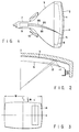
- a color cathode-ray tube comprises a panel 2, a funnel 3, a shadow mask 6, an electron gun 9, and a beam-deflecting unit 10, as illustrated in FIG. 1.
- the panel 2 and the funnel 3 are connected together, forming an envelope.
- the panel 2 has an effective part 1.
- a phosphor screen 4 Provided on the inner surface of the effective part 1 is a phosphor screen 4.
- the screen 4 consists of blue-emitting phosphor layers, green-emitting phosphor layers and red-emitting phosphor layers.
- the shadow mask 6 is provided in the envelope and faces the phosphor screen 4.
- the mask 6 has an effective part 5 which is substantially rectangular.
- the effective part 5 is curved and has arrays of apertures.
- the electron gun 9 is provided in the neck 7 of the funnel 3, for emitting three electron beams 8B, 8G and 8R.
- the beam-deflecting unit 10 is located outside the envelope, more precisely mounted on the funnel 3. In operation, the beams 8B, 8G and 8R emitted from the gun 9 are deflected in horizontal and vertical planes, pass through the apertures of the shadow mask 6, and are applied onto the phosphor screen 4, whereby the cathode-ray tube displays a color image.
- Various color cathode-ray tubes which have the structure described above are known.
- One of them is an in-line color cathode-ray tube, in which three electron beams 8B, 8G and 8R travel in the same horizontal plane.
- the blue-emitting phosphor layers, green-emitting phosphor layers and red-emitting phosphor layers which constitute the phosphor screen 4 of the in-line cathode-ray tube are elongated stripes which extend vertically.
- the shadow mask 6 of the cathode-ray tube has arrays of apertures in its effective part.
- the aperture arrays extend along the short axis Y of the effective part 5 and are juxtaposed along the long axis X of the effective part 5.
- the shadow mask 6 is a color-selecting electrode.
- the electron beams 8B, 8G and 8R are guided through each aperture of the mask 6, traveling at different angles with respect to the mask 6.
- the beams 8B, 8G and 8R must land correctly on the adjacent blue-emitting phosphor stripe, green-emitting phosphor stripe and red-emitting phosphor stripe of the screen 4, respectively. Otherwise, the in-line color cathode-ray tube cannot display an image having high color purity.
- the apertures of the shadow mask 6 need to be aligned with the phosphor stripes all the time the cathode-ray tube operates. More precisely, throughout the operation of the cathode-ray tube, the mask 6 must be held at such a position that the distance q between its effective part 5 and the effective part 1 of the panel 2 remains within a limited range.
- mislanding The erroneous electron-beam landing caused by the doming of the shadow mask 6 is known as "mislanding."
- the degree of mislanding greatly depends on the luminance of the image to display, the period of displaying that image, and the like.
- a so-called local doming develops as illustrated in FIG. 2 within a short period of time.
- the local doming causes great electron-beam mislanding.
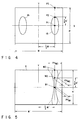
- a window-like pattern 14 was displayed on the phosphor screen of a color cathode-ray tube as shown in FIG. 3, by using a pattern signal generator. Formed by applying large-current electron beams to the screen, the pattern 14 had high luminance. It extended along the short axis Y of the phosphor screen.
- the window-like pattern 14 changed in shape and position, due to the electron-beam mislanding.
- the mislanding was the greatest when the pattern 14 was displayed at a distance of about W/3 from the short axis Y of the screen, where W is the width of the screen. To be more precise, the mislanding was most prominent in the elliptical region 15 of the screen, which is shown in FIG. 4.
- the deforming of the shadow mask is suppressed by the rigid frame which holds the shadow mask.
- the mislanding resulting from the thermal expansion of the shadow mask is the greatest when the pattern 14 is at a distance of about one-third the width W of the screen, from the short axis Y of the screen.
- the upper and lower edge parts of the shadow mask will be deformed but a little if the shadow mask expands when heated, because they are fastened to the frame which is rigid and strong. Furthermore, the frame which has heat capacity large enough to absorbs the thermal energy the left, right, upper and lower edge parts of the shadow mask generate when impinged with electron beams. This helps to reduce the deforming of the edge parts of the shadow mask.
- the electron-beam mislanding was most prominent in the elliptical region 15 (FIG. 4) of the phosphor screen.
- This region 15 faces an elliptical region of the shadow mask, whose center is on the long axis X of the mask and spaced from the short axis Y of the mask by about one-third the width of the mask and whose upper and lower edges are at a distance of about one-fourth the height of the mask, from the long axis X of the mask.
- the curvature of the effective part of the shadow mask is determined by the curvature of the inner surface of the effective panel part the deflection characteristic of the beam-deflecting unit, such that the effective parts of the mask and panel are spaced apart by an appropriate distance q. Therefore, when the curvature of the effective part of the mask is altered, the curvature of the inner surface of the effective panel part must be changed in the same fashion. To increase the curvature of the effective part of the mask, thereby to minimize the doming of the mask, it is necessary to increase the curvature of the inner surface of the effective panel part to the same value.
- the curvature of the inner surface of the effective panel part may not be increased in the case of a large-screen color cathode-ray tube and a recently developed color cathode-ray tube with a wide screen having an aspect ratio of 16:9. With these cathode-ray tubes there is the trend that the outer surface of the effective panel part has small curvature and is almost flat. If the curvature of the inner surface of the effective panel part is increased, the central part of the panel will be far more thinner than the edge parts, impairing the operating characteristic of the cathode-ray tube.
- the distance q between the effective parts of the mask and panel will be different from the desired value.
- the difference between the actual and desired values of the distance q can be compensated for by adjusting the intervals between the aperture arrays made in the effective part of the shadow mask.
- a shadow mask is known in which the intervals between the aperture arrays gradually increase from the short axis toward the left and right edge of the mask, and whose effective part is curved along the long axis at a large curvature. The effective part of this shadow mask cannot, however, be curved along the short axis, much enough to prevent the doming of the mask.
- the aperture arrays must be arranged such that the distance between any two adjacent aperture arrays gradually increases from the long axis of the mask toward the upper and lower edges of the mask. If all aperture arrays are so arranged, the effective part of the shadow mask cannot remain rectangular. Consequently, the cathode-ray tube cannot have a rectangular screen.
- Shadow masks free of this problem are disclosed in Jpn. Pat. Appln. KOKOKU Publication No. 5-1574 (corresponding to U.S. Patent No. 4,691,1398) and Jpn. Pat. Appln. KOKOKU Publication No. 5-42772 (corresponding to U.S. Patent No. 4,636,441).
- the shadow mask disclosed in either publication is characterized in that the aperture arrays are less spaced apart near either short axis than in each corner section.
- the corner sections can therefore be curved along the short axis at a small radius of curvature, while enabling a cathode-ray tube to have a rectangular screen.
- PH a + bX 2 + cX 4
- X and Y are coordinates in a coordinate system whose origin is the center of the effective part and whose axes are the horizontal and vertical axes of the effective part; and a, b and c are quadratic functions of Y.
- the distance PH changes as quadratic function of Y.
- the curvature at which the effective part of the mask is curved along the short axis Y can only be large uniformly.
- the local doming of the shadow mask can be suppressed, but not sufficiently to minimize the electron-beam mislanding in the elliptical region 15 (FIG. 4) of the phosphor screen.
- That part of the shadow mask through which the electron beams are applied onto the elliptical region 15 of the screen must be curved along the short axis Y at a great curvature. This part of the mask cannot be curved so unless PHM2 > PHM1. As shown in FIG.
- PHM1 is the distance between the two adjacent aperture arrays, measured at a point M1 which is located in the long axis X of the shadow mask 6 and which corresponds to the center P1 of the elliptical region 15 (FIG. 4) of the screen.
- PHM2 is the distance between the two adjacent aperture arrays, measured at a point M2 which is located in a distance of one-fourth the height H' of the effective part of the mask 6 from the long axis X of the mask 6 and which corresponds to the upper end P2 of the elliptical region 15 (FIG. 4) of the screen.
- the distance PHM2 is longer than the distance PHM1
- the distance PHM3 between the adjacent aperture arrays measured at a point M3 located on a long side of the rectangular shadow mask 6, will be longer than the distance PHM2 as is indicated by broken lines in FIG. 5.
- the distance PH between any two adjacent aperture arrays changes as a quadratic function of the distance Y from the long axis X of the effective part.
- the distance between other adjacent aperture arrays be extremely short at another points on the long side of the rectangular shadow mask. If the shadow mask 6 is curved in accordance with the distance on the point M3, the distance q between the effective part of the mask and the panel will be excessive long. As a consequence, the effective surface of the shadow mask is so curved as to be turned. Thus, the shadow can not be easily manufactured.
- a phosphor screen for used in color cathode-ray tubes is manufactured by photolithography.
- a phosphor slurry made of mainly blue-emitting phosphor and photosensitive resin is coated on the inner surface of the panel and subsequently dried, forming a phosphor layer.
- the phosphor layer is exposed to the light beams applied through the shadow mask.
- the layer, thus light-exposed, is developed, forming blue-emitting phosphor stripes on the inner surface of the panel.
- each phosphor layer In the step of exposing each phosphor layer to light beams are applied from a light source to the shadow mask through an optical lens system in the same paths as electron beams will be applied from the electron gun to the shadow mask.
- the light beams passing through the apertures of the shadow mask are applied onto each phosphor layer formed on the inner surface of the panel.
- the phosphor stripes formed by developing the phosphor layer therefore assume specific positional relation with the apertures of the mask.
- An in-line color cathode-ray tube has a phosphor screen consisting of blue-, green- and red-emitting phosphor stripes formed on the inner surface of the panel and black stripes and arranged between the phosphor stripes, and a shadow mask having vertical arrays of elongated apertures.
- an elongated light source is used which extends along the aperture arrays made in the shadow mask. The elongated light source serves to shorten the exposure time very much and to form a phosphor-stripe pattern with high precision.
- the inner surface of the panel is curved along not only the long axis X, but also the short axis Y.
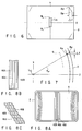
- the light beams Ep emitted from the ends AL and BL of the light source Ls pass through the apertures of the shadow mask 6, reaching points AP and BP on the inner surface of the panel 2.
- the points AP and BP are spaced apart in horizontal direction by a distance ⁇ 1, because the axis of the light source Ls and the axes of aperture arrays do not exist in the same plane. Consequently, although the phosphor stripes 16B, 16G and 16R provided on the central part of the panel 2 are straight as desired, as is illustrated in FIG.
- the phosphor stripes 16B, 16G and 16R are bent zigzag on the four edge parts of the panel 2, as is shown in FIG. 8B.
- the zigzagging of the stripes known as "light-source bending," lowers the quality of the edge parts of the phosphor screen.
- a shutter is used in the step of exposing each inner phosphor layer to light beams. That is, a movable shutter having a window is located between the panel and the shadow mask, preventing the entire phosphor layer from being exposed to light at a time.
- the elongated light source is inclined, so that the axis of the aperture pattern formed on the phosphor layer may be in the same plane as the axis of the elongated light source.
- This exposure method requires a complex exposure device and a long exposure time.
- a new method is widely employed, in which an optical lens system adjusts the path of the light beams applied from the elongated light source, applying the beams onto the entire phosphor layer at a time, without inclining the elongated light source.
- the phosphor stripes formed by the new exposure method are bent zigzag, though slightly, on the four edge parts of the panel, because an optical lens system is used.
- U.S. Patent No. 4,691,138 discloses two shadow masks which serve to form phosphor stripes which extend straight even on the four edge parts of the panel.
- the first mask has aperture arrays 18 made in its effective part 5.
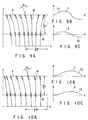
- those located near either long side of the effective part are not inclined at angles PI of positive values as indicted by the curve I shown in FIG. 9B.
- those located near an intermediate line 19 spaced from either long side of the effective part 5 by one-third the height H thereof are inclined at angles KII of negative values, as is indicated by the curve II shown in FIG. 9C.
- the second mask has aperture arrays 18 made in its effective part 5.
- those located near either long side of the effective part are inclined at various angles PI as indicated by the curve I shown in FIG. 10B.
- those located near an intermediate line 19 defined above are inclined at various angles PII as indicated by the curve II shown in FIG. 10C.
- An object of the present invention is to provide a color cathode-ray tube in which the shadow mask has aperture arrays juxtaposed at appropriate intervals and is curved to suppress a local doming of the effective part, and no electron-beam mislanding takes place on the phosphor screen.
- Another object of the invention is to provide a color cathode-ray tube in which the apertures of each array made in the shadow mask are inclined such that the phosphor stripes formed on the panel extend straight even on the four edge parts of the panel, and which can therefore display images having high color purity.
- a color cathode-ray tube which comprises a panel having a substantially rectangular effective part, a phosphor screen provided on the inner surface of the effective part of the panel, and a shadow mask having a curved, substantially rectangular effective part facing the phosphor screen and having a number of apertures.
- the apertures are arranged, forming a plurality of arrays which extend along the short axis of the effective part and juxtaposed along the long axis of the effective part.
- PH(N) A + BN 2 + CN 4
- A, B and C are fourth-degree functions of a Y-coordinate in a coordinate system whose origin is the center O of the effective part and whose axes are the horizontal and vertical axes of the effective part, and C is a function first decreasing and then increasing as the absolute value of the Y-coordinate.
- the distance PH(N) between the (N-1)th and Nth arrays, which are spaced about one-third the width W of the screen from the short axis of the screen, may increase with the absolute value of the Y-coordinate and may be represented by a fourth-degree function of the Y-coordinate so as to have a transition point in the effective part with respect to the short axis of the effective part.
- the distance PHM2 between measured at a point M2 which is located in a distance of one-fourth the height H of the effective part of the mask from the long axis X of the mask as shown in FIG. 5 can be longer than the distance PHM1 between the two adjacent aperture arrays, measured at a point M1 which is located in the long axis X of the shadow mask.
- the distance PHM3 between the adjacent aperture arrays, measured at a point M3 located above the point M2 as shown in FIG. 5, can be shorter than in the case where the distance between any two adjacent aperture arrays changes as a quadratic function of the distance Y from the long axis X of the effective part.
- the distance PH between any two adjacent aperture arrays changes as a fourth-degree function of the distance Y.
- the distance PHM3 can be sufficiently short even if the distance PHM2 is longer than the distance PHM1.
- a desired part of the effective part can therefore be curved along the short axis at a radium of curvature small enough to reduce the local doming of the shadow mask. As a result, the electron-beam mislanding on the phosphor screen can be minimized.
- a color cathode-ray tube which comprises a panel having a substantially rectangular effective part, a phosphor screen provided on the inner surface of the effective part of the panel, and a shadow mask having a curved, substantially rectangular effective part facing the phosphor screen and having a number of elongated apertures.
- the elongated apertures are arranged, forming arrays which extend along the short axis of the effective part and which are juxtaposed along the long axis of the effective part.
- the aperture arrays are curved in different ways.
- the elongated apertures are inclined at different angles to the short axis of the effective part.
- those located near either long side of the effective part are more inclined than those located near the long axis of the effective part.
- the angle changes from the short axis of the effective part toward either short side thereof, first increasing gradually to a maximum positive value and then decreasing to 0° or to a negative value.
- each elongated aperture assumes in the effective part is represented by coordinates (x, y) in a coordinate system whose origin is the center of the effective part and whose axes are the long axis X and short axis Y of the effective part, where x is a fourth-degree function or a higher-degree function of y.
- x is a fourth-degree function or a higher-degree function of y.
- the aperture arrays provided in this section are spaced apart by a long distance.
- the aperture arrays are spaced apart by a short distance along the long axis of the effective part, whereby the local doming of this section is suppressed sufficiently, whereby the cathode-ray tube can display images having high color purity.
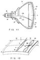
- FIG. 11 shows a color cathode-ray tube according to the first embodiment of the invention.
- the cathode-ray tube comprises a panel 21, a funnel 22, a phosphor screen 23, a shadow mask 25, an electron gun 28, and a beam-deflecting unit 29.
- the panel 21 and the funnel 22 are connected together, forming an envelope.
- the phosphor screen 23 is provided on the inner surface of the effective part 1 of the panel 21.
- the screen 23 consists of blue-emitting phosphor layers, green-emitting phosphor layers and red-emitting phosphor layers.
- the shadow mask 25 is provided in the envelope and faces the phosphor screen 23.
- the mask 25 has an effective part 24 which is substantially rectangular.
- the effective part 24 is curved and has apertures.
- the electron gun 28 is provided in the neck 26 of the funnel 22, for emitting three electron beams 27B, 27G and 27R.
- the beam-deflecting unit 29 is located outside the envelope, more precisely mounted on the funnel 22. In operation, the beams 27B, 27G and 27R emitted from the gun 28 are deflected in horizontal and vertical planes, pass through the apertures of the shadow mask 25, and are applied onto the phosphor screen 23, whereby the cathode-ray tube displays a color image.
- the apertures 31 are arranged in a plurality of arrays 32, which extend almost parallel to the short axis Y of the shadow mask 25 and are juxtaposed along the long axis X of the shadow mask 25.
- A, B and C are fourth-degree functions of a Y-coordinate in a coordinate system whose origin is the center O of the effective part and whose axes are the horizontal and vertical axes of the effective part, and C is a function first decreasing and then increasing as the absolute value of the Y-coordinate.
- the values for A and B changes with C such that the effective part 24 remains substantially rectangular.
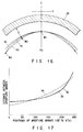
- FIG. 13 shows the relations N and PH(N) have along the long axis X.
- curve 33 shows the relation which N and PN(N) have along the long axis X of the effective part 24;
- curve 34 the relation which N and PH(N) have along the intermediate line extending parallel to the long side of the effective part 24 and spaced therefrom by one-fourth the height H' of the effective part 24;
- curve 35 the relation which N and PH(N) have along the long side of the effective part 24.
- the curves 33, 34 and 35 shown in FIG. 13 indicate that as Y increases, the C of CN4 changes differently along the long axis X of the effective part 24, the intermediate line between the long axis X and long side of the effective part 24 and the long side of the effective part 24. As curves 33 and 34 show, the C of CN4 decreases as Y increases.
- the curves 33 and 34 also teach that the distance PH(190M2) by which the 189th and 190th aperture arrays are spaced apart at point M2 (FIG. 5) on the intermediate line is longer than the distance PH(190M1) by which these two adjacent aperture arrays are spaced apart at point M1 (FIG. 5) at which an electron beam passes through the mask 25 before reaching point P1 (FIG.
- the distance PH(190M3) is shorter than the distance PH(190M2). It is by the distance PH(190M3) that the 189th and 190th aperture arrays are spaced apart at point M3 (FIG. 5) on the long side, at which an electron beam passes through the mask 25 before reaching point P3 (FIG. 4).
- the distance PH between the 189th and 190th aperture arrays of the shadow mask 25, which are spaced about one-third the width W of the screen 23 from the short axis Y of the screen 23, have values PH(190M1), PH(190M2) and PH(190M3) which have the following relationship: PH(190M2) > PH(190M3) > PH(190M1)
- FIG. 14 schematically illustrates the arrangement of the aperture arrays made in the upper-right section (the first quadrant) of the effective part 24 of the shadow mask 25. In this section of the effective part 24, most aperture arrays extend along the curves which are fourth-degree functions of the distance Y, and some aperture arrays close to the right edge of the effective part 24 extend almost straight.
- the effective part 24 is substantially rectangular.
- the distance PH between the 189th and 190th aperture arrays provided in that portion of the mask 25, where a local doming will most likely occur to cause electron-beam mislanding on the phosphor screen 23, gradually increases from the point M1 on the long axis X of the effective portion 34 toward the point M2. Then, the distance PH gradually decreases from the point M2 toward the point M3 on the long side of the effective part 24.
- the three electron beams must correctly land on blue-emitting, green-emitting and red-emitting phosphor stripes in order to display an image having a sufficient color purity on the phosphor screen 23 which is provided on the effective art of the panel 21.
- the distance q between the effective part 24 of the mask 24 and the effective part of the panel 21 needs to have an appropriate relation with the distance PH between any two adjacent aperture arrays 32.
- the distance q and the distance PH should have such a relation that the distance d between, for example, a red-emitting phosphor stripe 37R and the adjacent blue-emitting phosphor stripe 37B is two-thirds the distance PHP between the adjacent green-emitting phosphor stripes 37G as is illustrated in FIG. 15A.
- d will be less than two-thirds of the distance PHP as shown in FIG. 15B -- that is, d ⁇ 2/3 PHP. In this case, it is necessary to increase the distance q or decrease the distance PHP.
- the distance q is greater than the proper value, d will be greater than two-thirds of the distance PHP as shown in FIG. 15C -- that is, d > 2/3 PHP, and it is necessary to decrease the distance q or increase the distance PHP.
- light-absorbing stripes 38 are provided among the phosphor stripes 37B, 37G and 37R.
- the distance PH(190M2) is longer than the distance PH(190M1). It is by the distance PH(190M2) that the 189th and 190th aperture arrays are spaced apart along the intermediate line between the long axis X and long side of the effective part 24. It is by the distance PH(190M1) that the 189th and 190th aperture arrays are spaced apart along the long axis X of the effective part 24. Hence, the distance q may be increased to impart an appropriate relation to the distance q and the distance PH.
- a conventional shadow mask (hereinafter referred to as "first conventional shadow”), which has aperture arrays juxtaposed along the long axis such that the distance PH between any two adjacent aperture arrays does not change along the short axis Y, is curved along a curve 39 shown in FIG. 16, as viewed in a Y-Z plane containing the point M1 (FIG. 5).
- the conventional shadow mask 6 shown in FIG. 2 (hereinafter referred to as "second conventional mask”) which has aperture arrays juxtaposed along the long axis such that the distance PH between any two adjacent aperture arrays changes as a quadratic function of the distance Y from the long axis X, is curved along a curve 41 shown in FIG.
- the second conventional mask can have a longer distance q at the points M2 and M3 (FIG. 5) than the shadow mask which is curved along a curve 39 as viewed in the Y-Z plane.
- the second conventional mask therefore has a curvature along the short axis Y, large enough to reduce its local doming to some extent.
- the value the distance PH has at the point M3 is much greater than the value it has at the point M2.
- the second conventional mask must be curved in the opposite direction. To avoid this, the distance PH at the point M2 needs to be relatively short.
- the mask 25 is curved along a curve 40 shown in FIG. 16, as viewed in a Y-Z plane containing the point M1 (FIG. 5).
- the distance PH(190M3) at the point M3 is as short as in the second conventional mask, even if the distance PH(190M2) at the point M2 is longer than in the second conventional mask. Therefore, the mask 25 need not be curved in two opposite direction along the short axis Y.
- the distance q can be sufficiently long at the point M2, i.e., along the intermediate line, while the distance q along the upper and lower edge is as long as in the second conventional shadow mask.
- the effective part 24 has a curvature large enough to suppress the mislanding of the electron beams passing through the effective part 24 even if the effective part 24 underwent local doming.
- the radii Ry of curvature at which the first and second conventional masks and the shadow mask 25 are curved along the short axis Y are as shown in the following Table 1: Table 1 1st conventional mask 2nd conventional mask Shadow mask 25 On short axis 850 mm 750 mm 650 mm On intermediate line 850 mm 750 mm 800 mm On long side 850 mm 750 mm 2200 mm
- the radius Ry of curvature at which the shadow mask 25 is curved along the short axis Y, on the long axis X is 23% less than the radius Ry of curvature of the first conventional mask and 13% less than the radius Ry of the second conventional mask.
- the radius Ry of curvature of the shadow mask 25 is greater than that of the first conventional mask. Nonetheless the doming, if any, of the long side part of the shadow mask 25 is small since the mask frame holding this part has heat capacity large enough to absorbs the thermal energy which the mask 25 generate when impinged with electron beams. This helps to reduce the electron-beam mislanding, despite that the radius Ry of curvature of the mask 25 is relatively large. It has been found that the mislanding occurring in a color cathode-ray tube incorporating the shadow mask 25 is 14% less than the mislanding taking place in a color cathode-ray tube comprising the second conventional mask.
- a color cathode-ray tube according to a second embodiment of the invention will be described, with reference to FIGS. 17 and 18.
- the intervals between any two adjacent aperture arrays on the long axis X of the shadow mask are different from that on the long side of the rectangular shadow mask.
- the intervals between any two adjacent aperture arrays on the long axis X of the shadow mask are substantially same as that on the long side of the rectangular shadow mask.
- the aperture arrays 32 made in the effective part 24 of the shadow mask extend almost parallel to the short axis Y of the shadow mask and are juxtaposed along the long axis X of the shadow mask.
- the shadow mask of FIG. 18 is the same as the shadow mask 25 shown in FIG. 12, so far as this equation is concerned. However, the coefficients A, B and C have different values.
- a curve 33 shows how much the aperture arrays 32 are spaced apart along the long axis X of the effective part 24 of the mask
- a curve 34 shows how much the aperture arrays 32 are spaced apart along an intermediate line extending between the long axis X and long side of the effective part 24
- a curve 35 illustrates how much the aperture arrays 32 are spaced apart along the long side of the effective part 24.
- the intermediate line is spaced from the long axis X by one-fourth the height H' of the effective part 24.
- the curves 33 and 35 completely overlap. This means that any two adjacent aperture arrays are spaced apart by the same distance along the long axis X and the long side of the effective part 24.
- FIG. 18 schematically illustrates the arrangement of the aperture arrays made in the upper-right section (the first quadrant) of the effective part 24 of the shadow mask.
- the distance PH(N) between any two adjacent aperture arrays 32 is equal on the long axis X and the long side of the effective part 24.
- the distance PH(N) is longer near a point M2 than near a point M1 at which an electron beam may pass through the mask before reaching a region of the phosphor screen, where the electron-beam mislanding is most prominent.
- the point M1 is on the long axis X
- the point M2 is on the intermediate line spaced from the axis X by one-fourth the height H' of the effective part 24.
- the shadow mask having the aperture array arrangement shown in FIG. 18 achieves the same advantages as the shadow mask 25 incorporated in the first embodiment.
- a color cathode-ray tube according to a third embodiment of the invention will be described, with reference to FIG. 19A to 20B.
- a shadow mask of the third embodiment of the invention has aperture arrays having an arrangement shown in FIG. 19A.
- the shadow mask of FIG. 18 is the same as the shadow mask 25 shown in FIG. 12, so far as this equation is concerned.
- the coefficients A, B and C have different values.
- a curve 33 shows how much the aperture arrays 32 are spaced apart along the long axis X of the effective part 24 of the mask
- a curve 34 shows how much the aperture arrays 32 are spaced apart along an intermediate line extending between the long axis X and long side of the effective part 24
- a curve 35 illustrates how much the aperture arrays 32 are spaced apart along the long side of the effective part 24.
- the intermediate line is spaced from the long axis X by one-fourth the height H' of the effective part 24.
- the curves 34 and 35 completely overlap. This means that any two adjacent aperture arrays are spaced apart by the same distance along an intermediate line and the long side of the effective part 24.
- FIG. 20A schematically illustrates the arrangement of the aperture arrays made in the upper-right section (the first quadrant) of the effective part 24 of the shadow mask.
- the distance PH(N) between any two adjacent aperture arrays 32 is equal on the intermediate axis and the long side of the effective part 24.
- the distance PH(N) is longer near a point M2 than near a point M1 at which an electron beam may pass through the mask before reaching a region of the phosphor screen, where the electron-beam mislanding is most prominent.
- the point M1 is on the long axis X
- the point M2 is on the intermediate line spaced from the axis X by one-fourth the height H' of the effective part 24.
- the shadow mask having the aperture array arrangement shown in FIG. 19A achieves the same advantages as the shadow mask 25 incorporated in the first embodiment.
- the shadow mask has an aperture array arrangement shown in FIG. 19B.
- the shadow mask of FIG. 19B is the same as the shadow mask 25 shown in FIG. 12, so far as this equation is concerned.
- the coefficients A, B and C have different values.
- a curve 33 shows how much the aperture arrays 32 are spaced apart along the long axis X of the effective part 24 of the mask
- a curve 34 shows how much the aperture arrays 32 are spaced apart along an intermediate line extending between the long axis X and long side of the effective part 24 and spaced from the axis X by one-fourth the height H' of the effective part 24
- a curve 35 illustrates how much the aperture arrays 32 are spaced apart along the long side of the effective part 24.
- the distance PH(N) between any two adjacent aperture arrays located in an intermediate part of the effective part 24 first gradually increases from the short axis Y to the short side of the shadow mask and then gradually decreases from the intermediate part toward the short side of the effective part 24.
- FIG. 20B schematically illustrates the arrangement of the aperture arrays made in the upper-right section (the first quadrant) of the effective part 24 of the shadow mask.
- the distance between any two adjacent aperture arrays 32 can be obtained under the condition in which the coefficient C in the term CN4 of the above equation corresponding to the curve 34 set to have a minus value.
- the present invention can provide a color cathode-ray tube which comprises a panel having a substantially rectangular effective part, a phosphor screen provided on the inner surface of the effective part of the panel, and a shadow mask having a curved, substantially rectangular effective part facing the phosphor screen and having a number of apertures.
- the apertures are arranged, forming a plurality of arrays which extend along the short axis of the effective part and juxtaposed along the long axis of the effective part.
- PH(N) A + BN 2 + CN 4
- A, B and C are fourth-degree functions of a Y-coordinate in a coordinate system whose origin is the center O of the effective part and whose axes are the horizontal and vertical axes of the effective part, and C is a function first decreasing and then increasing as the absolute value of the Y-coordinate.
- the distance PH(N) between the (N-1)th and Nth arrays, which are spaced about one-third the width W of the screen from the short axis of the screen, may increase with the absolute value of the Y-coordinate and may be represented by a fourth-degree function of the Y-coordinate so as to have a transition point in the effective part with respect to the short axis of the effective part.
- the distance PH(N) can be optimized without altering the radium of curvature of the inner surface of the panel.
- the local doming of the shadow mask can therefore be reduced, suppressing the electron-beam mislanding on the phosphor screen.
- the color cathode-ray tube can display images having high color purity.
- a color cathode-ray tube according to the fourth embodiment of the present invention will be described, with reference to FIGS. 21A to 21C and FIGS. 22 to 24.
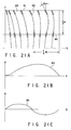
- FIG. 21A shows the aperture arrays made in the effective part 24 of the shadow mask which is incorporated in the color cathode-ray tube.
- each aperture 41 is an elongated one.
- the apertures are arranged, forming arrays 42 which extend along the short axis Y of the effective part and juxtaposed along the long axis X of the effective part. More precisely, the arrays 42 curve differently.
- the apertures of each array 42 are inclined to the short axis Y of the effective part 24.
- an aperture 41 will be considered to be inclined by a positive angle ⁇ if it is inclined toward the short axis Y of the effective part 24.
- all apertures 41 on the long side of the effective part 24 are inclined at positive angles ⁇ .
- the one located in a region to the short side from a line along the short axis, which passes through a point at a distance of one-fourth the width W of the effective part 24 from the short side thereof are inclined at the greatest positive angle ⁇ .
- some of the apertures 41 on an intermediate line 44 spaced from the long side of the effective part 24 by one-third the height H of the effective part 24 are inclined by positive angles ⁇ .
- the other apertures 41 on the line 44 are inclined at negative angles ⁇ . More specifically, for the apertures 41 on the intermediate line 44, the angle ⁇ gradually changes from the short axis Y toward the short side of the effective part 24, first increasing to a maximum positive value, then decreasing to a maximum negative value, and finally increasing to 0 ⁇ .
- an elongated light source 48 used to from the phosphor screen 23 by photolithography can be located, with its axis existing in the same plane as the axis of the aperture pattern formed on the inner source of the panel 21 as is illustrated in FIG. 22. Therefore, the phosphor stripes 47 formed by the photolithography are not bent zigzag, even on the four edge parts of the panel 21.
- the angle ⁇ gradually changes from the short axis Y toward the short side of the effective part 24, first increasing to a maximum positive value, then decreasing to a maximum negative value, and finally increasing to 0 ⁇ .
- two adjacent aperture arrays 42 are spaced apart more at a point P2 on the intermediate line 49 than at a point P1 on the long axis X or at a point P3 on the long side.
- the distance q between the effective part 24 of the shadow mask 25 and the inner surface of the effective panel part 20 is therefore long at the point P2 and short at the point P1.
- the effective part 24 of the mask 25 has a short radius Ry of curvature at the point P1. The local doming of the effective part 24 is suppressed effectively.
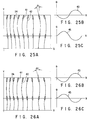
- a color cathode-ray tube according to the fifth embodiment of the invention will be described, with reference to FIGS. 25A, 25B and 25C.
- FIG. 25A shows the apertures 41 made in the shadow mask incorporated in this color cathode-ray tube.
- the angle ⁇ gradually changes from the short axis Y of the effective part 24 toward the short side of thereof, first decreasing to a maximum negative value, then increasing to a maximum positive value, and finally decreasing to 0 ⁇ .
- the angle ⁇ gradually changes from the short axis Y toward the short side of the effective part 24, first increasing to a maximum positive value, then decreasing to a maximum negative value, and finally increasing to 0 ⁇ .
- the apertures 41 are more inclined than the apertures of the shadow mask (FIG. 21A) incorporated in the fourth embodiment, so as to form phosphor stripes by photolithography, which are not bent zigzag, even on the four edge parts of the panel 21.
- the apertures 41 located near the point P2 (FIG. 4) on an intermediate line parallel to the long axis X are inclined very much, whereby the effective part 24 has a shorter radius Ry of curvature at the point P1.
- the local doming of the effective part 24 is suppressed more effectively than in the shadow mask provided in the fourth embodiment.
- the position which the center of each aperture 41 assumes in the effective part 24 can be represented by coordinates (x, y) in a coordinate system whose origin is the center of the effective part 24 and whose axes are the long axis X and short axis Y of the effective part 24. If the upper and lower halves of the effective part 24 are symmetrical with respect to the long axis X, the position of the aperture 41 is represented as an even function, provided that x is a fourth-degree function or a higher-degree function of y.
- a color cathode-ray tube according to the sixth embodiment of the invention will be described, with reference to FIGS. 26A, 26B and 26C.
- the shadow mask incorporated in this cathode-ray tube is characterized in that its upper and lower halves are symmetrical with respect to the long axis Y.
- FIG. 26A shows the apertures 41 made in the effective part 24 of the shadow mask.
- the position of each aperture 41 is represented by coordinates (x, y) in a coordinate system whose origin is the center of the effective part 24 and whose axes are the long axis X and short axis Y of the effective part 24.
- the value for x is a sixth-degree function of y.
- the arrays 42 of apertures meander, and the apertures 41 are inclined to the short axis Y of the effective part 24.
- the angle ⁇ gradually changes from the short axis Y of the effective part 24 toward the short side of thereof, first decreasing to a maximum negative value, then increasing to a maximum positive value, and finally decreasing to 0 ⁇ as indicated by the curve 43 shown in FIG. 26B.
- the angle ⁇ gradually changes from the short axis Y toward the short side of the effective part 24, first increasing to a maximum positive value, then decreasing to a maximum negative value, and finally increasing to 0 ⁇ as indicated by the curve 45 shown in FIG. 26C.
- the shadow mask shown in FIG. 26A achieves the same advantages as the shadow mask (FIG. 25A) incorporated in the fifth embodiment, though it differs in that x is a higher-degree function of y.
- the present invention can provide a color cathode-ray tube which comprises a panel having a substantially rectangular effective part, a phosphor screen provided on the inner surface of the effective part of the panel, and a shadow mask having a curved, substantially rectangular effective part facing the phosphor screen and having a number of elongated apertures.
- the elongated apertures are arranged, forming arrays which extend along the short axis of the effective part and which are juxtaposed along the long axis of the effective part.
- the aperture arrays are curved in different ways.
- the elongated apertures are inclined at different angles to the short axis of the effective part.
- the phosphor stripes formed by the photolithography are not bent zigzag, even on the four edge parts of the panel. Further, since the angles of the elongated apertures made in the section extending for one-third the height of the effective part from either long side thereof change as described above, the distance between any two adjacent aperture arrays in this section is relatively long. This section of the effective part therefore has a shorter radius of curvature. As a result, the local doming of the section is suppressed sufficiently, whereby the cathode-ray tube can display images having high color purity.
Landscapes
- Electrodes For Cathode-Ray Tubes (AREA)
Abstract
Description
- The present invention relates to a color cathode-ray tube of shadow mask type, and more particularly to a color cathode-ray tube comprising a phosphor screen and a shadow mask which has an effective part having arrays of apertures extending parallel to the short axis of the effective part and juxtaposed along the long axis thereof. The aperture arrays are spaced apart, and the apertures of each array are inclined such that electron beams passing through the apertures of the shadow mask land at desired positions on the phosphor screen, enhancing the quality of the phosphor screen.
- Generally, a color cathode-ray tube comprises a
panel 2, afunnel 3, ashadow mask 6, anelectron gun 9, and a beam-deflectingunit 10, as illustrated in FIG. 1. Thepanel 2 and thefunnel 3 are connected together, forming an envelope. Thepanel 2 has an effective part 1. Provided on the inner surface of the effective part 1 is aphosphor screen 4. Thescreen 4 consists of blue-emitting phosphor layers, green-emitting phosphor layers and red-emitting phosphor layers. Theshadow mask 6 is provided in the envelope and faces thephosphor screen 4. Themask 6 has aneffective part 5 which is substantially rectangular. Theeffective part 5 is curved and has arrays of apertures. Theelectron gun 9 is provided in theneck 7 of thefunnel 3, for emitting threeelectron beams unit 10 is located outside the envelope, more precisely mounted on thefunnel 3. In operation, thebeams gun 9 are deflected in horizontal and vertical planes, pass through the apertures of theshadow mask 6, and are applied onto thephosphor screen 4, whereby the cathode-ray tube displays a color image. - Various color cathode-ray tubes which have the structure described above are known. One of them is an in-line color cathode-ray tube, in which three
electron beams phosphor screen 4 of the in-line cathode-ray tube are elongated stripes which extend vertically. Theshadow mask 6 of the cathode-ray tube has arrays of apertures in its effective part. The aperture arrays extend along the short axis Y of theeffective part 5 and are juxtaposed along the long axis X of theeffective part 5. - The
shadow mask 6 is a color-selecting electrode. Theelectron beams mask 6, traveling at different angles with respect to themask 6. Thebeams screen 4, respectively. Otherwise, the in-line color cathode-ray tube cannot display an image having high color purity. To achieve correct landing of the beams, the apertures of theshadow mask 6 need to be aligned with the phosphor stripes all the time the cathode-ray tube operates. More precisely, throughout the operation of the cathode-ray tube, themask 6 must be held at such a position that the distance q between itseffective part 5 and the effective part 1 of thepanel 2 remains within a limited range. - Due to the operating principle of a shadow-mask type color cathode-ray tube, only one third or less of each electron beam emitted from the gun passes through an aperture of the
shadow mask 6 and reaches thephosphor screen 4. The other part of the electron beam impinges on themask 6 and is converted into thermal energy, heating theshadow mask 6. Thus heated, theshadow mask 6 warps toward thephosphor screen 4 as indicated by the one-dot, one-dash line shown in FIG. 2, because it is made of low-carbon steel which has a large coefficient of thermal expansion. Due to this warping, known as "doming," the apertures change their positions. Consequently, the distance q between itseffective part 5 and the effective part 1 of thepanel 2 decreases. If the distance q excessively decreases to a value outside the limited range, each electron beam will fail to land on thetarget phosphor stripe 11, and the cathode-ray tube will display an image having insufficient color purity. - The erroneous electron-beam landing caused by the doming of the
shadow mask 6 is known as "mislanding." The degree of mislanding greatly depends on the luminance of the image to display, the period of displaying that image, and the like. When the image displayed has a high-luminance part, a so-called local doming develops as illustrated in FIG. 2 within a short period of time. The local doming causes great electron-beam mislanding. - To analyze the mislanding caused by local doming, experiments were conducted. In the experiments, a window-
like pattern 14 was displayed on the phosphor screen of a color cathode-ray tube as shown in FIG. 3, by using a pattern signal generator. Formed by applying large-current electron beams to the screen, thepattern 14 had high luminance. It extended along the short axis Y of the phosphor screen. - The window-
like pattern 14 changed in shape and position, due to the electron-beam mislanding. The mislanding was the greatest when thepattern 14 was displayed at a distance of about W/3 from the short axis Y of the screen, where W is the width of the screen. To be more precise, the mislanding was most prominent in theelliptical region 15 of the screen, which is shown in FIG. 4. - Why the electron-beam mislanding was most prominent in the
region 15 will be discussed with reference to FIG.5. If thepattern 14 is displayed in the central region of the screen shown in FIG. 3, the central part of the shadow mask will undergo thermal expansion. In this case, the mislanding of beams will be trivial since the beams passing through the apertures made in that central part are deflected by small angles. The farther thepattern 14 is located from the short axis Y of the screen, the greater the incident angles of the electron beams applied to form the pattern. The greater the incident angles, the more prominent the electron-beam mislanding of the beams. Nonetheless, if thepattern 14 is displayed in the left or right edge region of the screen, the mislanding will be small. This is because the deforming of the shadow mask is suppressed by the rigid frame which holds the shadow mask. Hence, the mislanding resulting from the thermal expansion of the shadow mask is the greatest when thepattern 14 is at a distance of about one-third the width W of the screen, from the short axis Y of the screen. - The upper and lower edge parts of the shadow mask will be deformed but a little if the shadow mask expands when heated, because they are fastened to the frame which is rigid and strong. Furthermore, the frame which has heat capacity large enough to absorbs the thermal energy the left, right, upper and lower edge parts of the shadow mask generate when impinged with electron beams. This helps to reduce the deforming of the edge parts of the shadow mask.
- Thus, the electron-beam mislanding was most prominent in the elliptical region 15 (FIG. 4) of the phosphor screen. This
region 15 faces an elliptical region of the shadow mask, whose center is on the long axis X of the mask and spaced from the short axis Y of the mask by about one-third the width of the mask and whose upper and lower edges are at a distance of about one-fourth the height of the mask, from the long axis X of the mask. - Various methods have been devised to minimize the doming of a shadow mask. One of them is to impart a large curvature to the effective part of the shadow mask, that is, to increase the radius of curvature of the effective part. As experiments show, the doming can be reduced more effectively by decreasing the curvature along the short axis of the mask than by decreasing the curvature along the long axis.
- The curvature of the effective part of the shadow mask is determined by the curvature of the inner surface of the effective panel part the deflection characteristic of the beam-deflecting unit, such that the effective parts of the mask and panel are spaced apart by an appropriate distance q. Therefore, when the curvature of the effective part of the mask is altered, the curvature of the inner surface of the effective panel part must be changed in the same fashion. To increase the curvature of the effective part of the mask, thereby to minimize the doming of the mask, it is necessary to increase the curvature of the inner surface of the effective panel part to the same value. The curvature of the inner surface of the effective panel part may not be increased in the case of a large-screen color cathode-ray tube and a recently developed color cathode-ray tube with a wide screen having an aspect ratio of 16:9. With these cathode-ray tubes there is the trend that the outer surface of the effective panel part has small curvature and is almost flat. If the curvature of the inner surface of the effective panel part is increased, the central part of the panel will be far more thinner than the edge parts, impairing the operating characteristic of the cathode-ray tube.
- If the curvature of the effective mask part is increased, while the curvature of the inner surface of the effective panel part remains relatively small, the distance q between the effective parts of the mask and panel will be different from the desired value. As is known in the art, the difference between the actual and desired values of the distance q can be compensated for by adjusting the intervals between the aperture arrays made in the effective part of the shadow mask. A shadow mask is known in which the intervals between the aperture arrays gradually increase from the short axis toward the left and right edge of the mask, and whose effective part is curved along the long axis at a large curvature. The effective part of this shadow mask cannot, however, be curved along the short axis, much enough to prevent the doming of the mask. To increase the curvature along the short axis, the aperture arrays must be arranged such that the distance between any two adjacent aperture arrays gradually increases from the long axis of the mask toward the upper and lower edges of the mask. If all aperture arrays are so arranged, the effective part of the shadow mask cannot remain rectangular. Consequently, the cathode-ray tube cannot have a rectangular screen.
- Shadow masks free of this problem are disclosed in Jpn. Pat. Appln. KOKOKU Publication No. 5-1574 (corresponding to U.S. Patent No. 4,691,1398) and Jpn. Pat. Appln. KOKOKU Publication No. 5-42772 (corresponding to U.S. Patent No. 4,636,441). The shadow mask disclosed in either publication is characterized in that the aperture arrays are less spaced apart near either short axis than in each corner section. The corner sections can therefore be curved along the short axis at a small radius of curvature, while enabling a cathode-ray tube to have a rectangular screen.
- The distance PH between any two adjacent aperture arrays is given as:

- As the distance Y from the long axis X of the effective part changes, the distance PH changes as quadratic function of Y. The curvature at which the effective part of the mask is curved along the short axis Y can only be large uniformly. The local doming of the shadow mask can be suppressed, but not sufficiently to minimize the electron-beam mislanding in the elliptical region 15 (FIG. 4) of the phosphor screen. To minimize the local doming, that part of the shadow mask through which the electron beams are applied onto the
elliptical region 15 of the screen must be curved along the short axis Y at a great curvature. This part of the mask cannot be curved so unless PHM2 > PHM1. As shown in FIG. 5, PHM1 is the distance between the two adjacent aperture arrays, measured at a point M1 which is located in the long axis X of theshadow mask 6 and which corresponds to the center P1 of the elliptical region 15 (FIG. 4) of the screen. As shown in FIG. 5, too, PHM2 is the distance between the two adjacent aperture arrays, measured at a point M2 which is located in a distance of one-fourth the height H' of the effective part of themask 6 from the long axis X of themask 6 and which corresponds to the upper end P2 of the elliptical region 15 (FIG. 4) of the screen. If the distance PHM2 is longer than the distance PHM1, however, the distance PHM3 between the adjacent aperture arrays, measured at a point M3 located on a long side of therectangular shadow mask 6, will be longer than the distance PHM2 as is indicated by broken lines in FIG. 5. This is inevitably because the distance PH between any two adjacent aperture arrays changes as a quadratic function of the distance Y from the long axis X of the effective part. For theshadow mask 6 to have a rectangular effective part, it is required that the distance between other adjacent aperture arrays be extremely short at another points on the long side of the rectangular shadow mask. If theshadow mask 6 is curved in accordance with the distance on the point M3, the distance q between the effective part of the mask and the panel will be excessive long. As a consequence, the effective surface of the shadow mask is so curved as to be turned. Thus, the shadow can not be easily manufactured. - Generally, a phosphor screen for used in color cathode-ray tubes is manufactured by photolithography. To be more specific, first, a phosphor slurry made of mainly blue-emitting phosphor and photosensitive resin is coated on the inner surface of the panel and subsequently dried, forming a phosphor layer. Then, the phosphor layer is exposed to the light beams applied through the shadow mask. The layer, thus light-exposed, is developed, forming blue-emitting phosphor stripes on the inner surface of the panel. The sequence of these steps are repeated for two phosphor slurries containing green-emitting phosphor and red-emitting phosphor, respectively, thereby forming green-emitting phosphor stripes and red-emitting phosphor stripes on the inner surface of the panel.
- In the step of exposing each phosphor layer to light beams are applied from a light source to the shadow mask through an optical lens system in the same paths as electron beams will be applied from the electron gun to the shadow mask. The light beams passing through the apertures of the shadow mask are applied onto each phosphor layer formed on the inner surface of the panel. The phosphor stripes formed by developing the phosphor layer therefore assume specific positional relation with the apertures of the mask. An in-line color cathode-ray tube has a phosphor screen consisting of blue-, green- and red-emitting phosphor stripes formed on the inner surface of the panel and black stripes and arranged between the phosphor stripes, and a shadow mask having vertical arrays of elongated apertures. Even if the spot an electron beam passing through one of the apertures forms on the target phosphor stripe moves in the lengthwise direction of the stripe (namely, along the short axis Y of the phosphor screen), the color purity will not affected. Therefore it is unnecessary to apply light beams to the shadow mask in the substantially same paths as the electron gun will emits electron beams to the shadow mask. To form a phosphor screen in the inline color cathode-ray tube, an elongated light source is used which extends along the aperture arrays made in the shadow mask. The elongated light source serves to shorten the exposure time very much and to form a phosphor-stripe pattern with high precision.
- A problem will arise if an elongated light source is used. The inner surface of the panel is curved along not only the long axis X, but also the short axis Y. Thus, as shown in FIGS. 6 and 7, the light beams Ep emitted from the ends AL and BL of the light source Ls pass through the apertures of the
shadow mask 6, reaching points AP and BP on the inner surface of thepanel 2. The points AP and BP are spaced apart in horizontal direction by a distance Δ1, because the axis of the light source Ls and the axes of aperture arrays do not exist in the same plane. Consequently, although thephosphor stripes panel 2 are straight as desired, as is illustrated in FIG. 8A, thephosphor stripes panel 2, as is shown in FIG. 8B. The zigzagging of the stripes, known as "light-source bending," lowers the quality of the edge parts of the phosphor screen. - In order to prevent a decrease in the quality of the phosphor screen, a shutter is used in the step of exposing each inner phosphor layer to light beams. That is, a movable shutter having a window is located between the panel and the shadow mask, preventing the entire phosphor layer from being exposed to light at a time. When the shutter is moved, the elongated light source is inclined, so that the axis of the aperture pattern formed on the phosphor layer may be in the same plane as the axis of the elongated light source. This exposure method requires a complex exposure device and a long exposure time. Recently, a new method is widely employed, in which an optical lens system adjusts the path of the light beams applied from the elongated light source, applying the beams onto the entire phosphor layer at a time, without inclining the elongated light source. The phosphor stripes formed by the new exposure method are bent zigzag, though slightly, on the four edge parts of the panel, because an optical lens system is used.
- U.S. Patent No. 4,691,138 (KOKOKU Publication No. 5-1574) discloses two shadow masks which serve to form phosphor stripes which extend straight even on the four edge parts of the panel.
- As shown in FIG. 9A, the first mask has
aperture arrays 18 made in itseffective part 5. Of the apertures made in the section extending for one-fourth the width W of theeffective part 5 from either short side thereof, those located near either long side of the effective part are not inclined at angles PI of positive values as indicted by the curve I shown in FIG. 9B. Further, of these apertures, those located near anintermediate line 19 spaced from either long side of theeffective part 5 by one-third the height H thereof are inclined at angles KII of negative values, as is indicated by the curve II shown in FIG. 9C. As shown in FIG. 10A, the second mask hasaperture arrays 18 made in itseffective part 5. Of the apertures made in the section defined above, those located near either long side of the effective part are inclined at various angles PI as indicated by the curve I shown in FIG. 10B. Of these apertures, those located near anintermediate line 19 defined above are inclined at various angles PII as indicated by the curve II shown in FIG. 10C. - In either shadow mask disclosed in U.S. Patent No. 4,631,441, the apertures made in each corner section of the
effective part 5 are not inclined sufficiently to prevent the forming of zigzag phosphor stripes. - An object of the present invention is to provide a color cathode-ray tube in which the shadow mask has aperture arrays juxtaposed at appropriate intervals and is curved to suppress a local doming of the effective part, and no electron-beam mislanding takes place on the phosphor screen.
- Another object of the invention is to provide a color cathode-ray tube in which the apertures of each array made in the shadow mask are inclined such that the phosphor stripes formed on the panel extend straight even on the four edge parts of the panel, and which can therefore display images having high color purity.
- According to an aspect of the invention, there is provided a color cathode-ray tube which comprises a panel having a substantially rectangular effective part, a phosphor screen provided on the inner surface of the effective part of the panel, and a shadow mask having a curved, substantially rectangular effective part facing the phosphor screen and having a number of apertures. The apertures are arranged, forming a plurality of arrays which extend along the short axis of the effective part and juxtaposed along the long axis of the effective part. The distance PH(N) between the (N-1)th and Nth arrays, counted from the array passing the center O of the effective part, is given as:

- The distance PH(N) between the (N-1)th and Nth arrays, which are spaced about one-third the width W of the screen from the short axis of the screen, may increase with the absolute value of the Y-coordinate and may be represented by a fourth-degree function of the Y-coordinate so as to have a transition point in the effective part with respect to the short axis of the effective part.
- Since the distance between any two adjacent aperture arrays is so set, the distance PHM2 between measured at a point M2 which is located in a distance of one-fourth the height H of the effective part of the mask from the long axis X of the mask as shown in FIG. 5 can be longer than the distance PHM1 between the two adjacent aperture arrays, measured at a point M1 which is located in the long axis X of the shadow mask. Moreover, the distance PHM3 between the adjacent aperture arrays, measured at a point M3 located above the point M2 as shown in FIG. 5, can be shorter than in the case where the distance between any two adjacent aperture arrays changes as a quadratic function of the distance Y from the long axis X of the effective part. The distance PH between any two adjacent aperture arrays changes as a fourth-degree function of the distance Y. Thus, the distance PHM3 can be sufficiently short even if the distance PHM2 is longer than the distance PHM1. A desired part of the effective part can therefore be curved along the short axis at a radium of curvature small enough to reduce the local doming of the shadow mask. As a result, the electron-beam mislanding on the phosphor screen can be minimized.
- According to another aspect of the invention, there is provided a color cathode-ray tube which comprises a panel having a substantially rectangular effective part, a phosphor screen provided on the inner surface of the effective part of the panel, and a shadow mask having a curved, substantially rectangular effective part facing the phosphor screen and having a number of elongated apertures. The elongated apertures are arranged, forming arrays which extend along the short axis of the effective part and which are juxtaposed along the long axis of the effective part. The aperture arrays are curved in different ways. The elongated apertures are inclined at different angles to the short axis of the effective part. More precisely, of the apertures made in the section extending for one-fourth the width of the effective part from either short side thereof, those located near either long side of the effective part are more inclined than those located near the long axis of the effective part. For the apertures made in the section extending for one-third the height of the effective part from either long side thereof, the angle changes from the short axis of the effective part toward either short side thereof, first increasing gradually to a maximum positive value and then decreasing to 0° or to a negative value.
- The position each elongated aperture assumes in the effective part is represented by coordinates (x, y) in a coordinate system whose origin is the center of the effective part and whose axes are the long axis X and short axis Y of the effective part, where x is a fourth-degree function or a higher-degree function of y. Thus, the apertures made in any corner of the effective part are more inclined than those made in any other portion of the effective part. An elongated light source used to from the phosphor screen can therefore be located, with its axis existing in the same plane as the axis of the aperture pattern formed on the inner surface of the panel. Hence, the phosphor stripes formed are not bent zigzag, even on the four edge parts of the panel. Furthermore, since the inclination angle of the apertures made in the section extending for one-third the height of the effective part from either long side thereof changes from the short axis of the effective part toward either short side thereof, first increasing gradually to a maximum positive value and then decreasing to 0° or to a negative value, the aperture arrays provided in this section are spaced apart by a long distance. On the other hand, the aperture arrays are spaced apart by a short distance along the long axis of the effective part, whereby the local doming of this section is suppressed sufficiently, whereby the cathode-ray tube can display images having high color purity. This invention can be more fully understood from the following detailed description when taken in conjunction with the accompanying drawings, in which:
- FIG. 1 is a sectional view of a conventional color cathode-ray tube;
- FIG. 2 is a diagram explaining the electron-beam mislanding which occurs in the cathode-ray tube shown in FIG. 1, due to the doming of the shadow mask;
- FIG. 3 is a diagram explaining how a local doming of the shadow mask takes place in the cathode-ray tube shown in FIG. 1;
- FIG. 4 is a diagram showing the region of the phosphor screen, where the electron-beam mislanding occurs due to the local doming of the shadow mask shown in FIG. 3;
- FIG. 5 is a diagram explaining the problem with a conventional shadow mask in which the distance between any two adjacent aperture arrays increases as a quadratic function of the distance Y from the long axis X of the effective part;
- FIG. 6 is a diagram explaining why the phosphor stripes are bent zigzag on the four edge parts of the panel in a conventional color cathode-ray tube;
- FIG. 7 is another diagram explaining why the phosphor stripes are bent zigzag on the four edge parts of the panel in the conventional color cathode-ray tube;
- FIG. 8A is a plan view of the phosphor screen of the conventional color cathode-ray tube;
- FIG. 8B is a diagram showing the shape of the phosphor stripes formed on the central part of the panel;
- FIG. 8C is a diagram illustrating the shape of the phosphor stripes formed on the four edge parts of the panel;
- FIG. 9A is a diagram showing the aperture arrays made in a conventional shadow mask;
- FIG. 9B is a graph representing how much the apertures arranged along the long side of the conventional shadow mask are inclined to the short axis Y of the mask;
- FIG. 9C is a graph representing how much the apertures arranged along an intermediate line spaced from the long side of the mask by one-third the height of the effective part of the mask are inclined to the short axis Y of the conventional shadow mask;
- FIG. 10A is a diagram showing the aperture arrays made in another conventional shadow mask;
- FIG. 10B is a graph representing how much the apertures arranged along the long side of the mask shown in FIG. 10A are inclined to the short axis of the mask;
- FIG. 10C is a graph representing how much the apertures arranged along an intermediate line spaced from the long side of the mask are inclined to the short axis Y of the shadow mask;
- FIG. 11 is a sectional view of a color cathode-ray tube according to a first embodiment of the present invention;
- FIG. 12 is a perspective view of the shadow mask incorporated in the cathode-ray tube shown in FIG. 11;
- FIG. 13 is a graph representing how much the aperture arrays are spaced apart along the long axis X and long side of the effective part of the shadow mask shown in FIG. 12 and along an intermediate line extending between the long axis X and long side of the effective part;
- FIG. 14 is a diagram showing the arrangement of the aperture arrays made in the shadow mask shown in FIG. 12;
- FIGS. 15A, 15B and 15C are diagrams, each showing a relation among the distance between the shadow mask and the inner surface of the panel, the distance between any two adjacent aperture arrays, and the distance between any two adjacent phosphor stripes;
- FIG. 16 is a diagram showing three curves along which the shadow mask shown in FIG. 12, a first conventional shadow mask and a second conventional shadow mask are curved along the short axis;
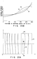
- FIG. 17 is a graph representing how much the aperture arrays made in the effective part of a shadow mask used in a color cathode-ray tube according to a second embodiment of the invention are spaced apart along the long axis X and long side of the effective part and along an intermediate line extending between the long axis X and long side of the effective part;
- FIG. 18 is a plan view schematically showing the arrangement of the aperture arrays made in the shadow mask shown in FIG. 17;
- FIGS. 19A and 19B are a diagram representing how much the aperture arrays made in the effective part of a shadow mask incorporated in a color cathode-ray tube according to a third embodiment of the invention are spaced apart along the long axis X and long side of the effective part and along an intermediate line extending between the long axis X and long side of the effective part;
- FIGS. 20A and 20B are plan views schematically showing the arrangement of the aperture arrays made in the shadow mask shown in FIG. 19;
- FIG. 21A is a diagram showing the aperture arrays made in the shadow mask incorporated in a color cathode-ray tube according to a fourth embodiment of the present invention;
- FIG. 21B is a graph representing how much the apertures arranged along the long side of the mask shown in FIG. 21A are inclined to the short axis of the mask;
- FIG. 21C is a graph representing how much the apertures arranged along an intermediate line spaced from the long side of the mask are inclined to the short axis Y of the shadow mask;
- FIG. 22 is a perspective view illustrating the positional relation between the elongated light source for applying light on phosphor layers and the aperture arrays made in the shadow mask shown in FIG. 21A;
- FIG. 23 is a diagram showing how much the aperture arrays made in the effective part of the shadow mask shown in FIG. 21A are spaced apart along the long axis X of the effective part;
- FIG. 24 is a diagram explaining how the doming of the shadow mask shown in FIG. 23 is suppressed;
- FIG. 25A is a diagram showing the apertures made in the shadow mask incorporated in a color cathode-ray tube according to a fifth embodiment of the invention;
- FIG. 25B is a graph representing how much the apertures arranged along the long side of the mask are inclined to the short axis Y of the mask shown in FIG. 25A;
- FIG. 25C is a graph representing how much the apertures arranged along an intermediate line spaced from the long side of the mask are inclined to the short axis Y of the mask shown in FIG. 25A;
- FIG. 26A is a diagram showing the apertures made in the shadow mask incorporated in a color cathode-ray tube according to a sixth embodiment of the invention;
- FIG. 26B is a graph representing how much the apertures arranged along the long side of the mask are inclined to the short axis Y of the mask shown in FIG. 26A; and
- FIG. 26C is a graph representing how much the apertures arranged along an intermediate line spaced from the long side of the mask are inclined to the short axis Y of the mask shown in FIG. 26A.
- Embodiments of the present invention, which are color cathode-ray tubes, will be described in detail with reference to the accompanying drawings.
- FIG. 11 shows a color cathode-ray tube according to the first embodiment of the invention. As shown in FIG. 11, the cathode-ray tube comprises a
panel 21, afunnel 22, aphosphor screen 23, ashadow mask 25, anelectron gun 28, and a beam-deflectingunit 29. Thepanel 21 and thefunnel 22 are connected together, forming an envelope. Thephosphor screen 23 is provided on the inner surface of the effective part 1 of thepanel 21. Thescreen 23 consists of blue-emitting phosphor layers, green-emitting phosphor layers and red-emitting phosphor layers. Theshadow mask 25 is provided in the envelope and faces thephosphor screen 23. Themask 25 has aneffective part 24 which is substantially rectangular. Theeffective part 24 is curved and has apertures. Theelectron gun 28 is provided in theneck 26 of thefunnel 22, for emitting threeelectron beams unit 29 is located outside the envelope, more precisely mounted on thefunnel 22. In operation, thebeams gun 28 are deflected in horizontal and vertical planes, pass through the apertures of theshadow mask 25, and are applied onto thephosphor screen 23, whereby the cathode-ray tube displays a color image. - As shown in FIG. 12, the
apertures 31 are arranged in a plurality ofarrays 32, which extend almost parallel to the short axis Y of theshadow mask 25 and are juxtaposed along the long axis X of theshadow mask 25. The distance PH(N) between the (N-1)th andNth arrays 32, counted from thearray 32 passing the center O of theeffective part 24, is given as:
effective part 24 remains substantially rectangular. - Assume that the
shadow mask 25 has 500 aperture arrays that 250 aperture arrays are juxtaposed on each side of the short axis Y, from the center O of theeffective part 24 toward the left or right edge. FIG. 13 shows the relations N and PH(N) have along the long axis X. To be more specific,curve 33 shows the relation which N and PN(N) have along the long axis X of theeffective part 24;curve 34 the relation which N and PH(N) have along the intermediate line extending parallel to the long side of theeffective part 24 and spaced therefrom by one-fourth the height H' of theeffective part 24; andcurve 35 the relation which N and PH(N) have along the long side of theeffective part 24. - The
curves effective part 24, the intermediate line between the long axis X and long side of theeffective part 24 and the long side of theeffective part 24. Ascurves curves mask 25 before reaching point P1 (FIG. 4) located in the long axis X of thescreen 23 and at one-third the width W of thescreen 23 from the short axis Y of thescreen 23. As the distance Y increases, the fourth-degree function C of N increases. As can be understood from thecurve 35, the distance PH(190M3) is shorter than the distance PH(190M2). It is by the distance PH(190M3) that the 189th and 190th aperture arrays are spaced apart at point M3 (FIG. 5) on the long side, at which an electron beam passes through themask 25 before reaching point P3 (FIG. 4). - Namely, the distance PH between the 189th and 190th aperture arrays of the
shadow mask 25, which are spaced about one-third the width W of thescreen 23 from the short axis Y of thescreen 23, have values PH(190M1), PH(190M2) and PH(190M3) which have the following relationship:
effective part 24 of theshadow mask 25. In this section of theeffective part 24, most aperture arrays extend along the curves which are fourth-degree functions of the distance Y, and some aperture arrays close to the right edge of theeffective part 24 extend almost straight. That is,theeffective part 24 is substantially rectangular. The distance PH between the 189th and 190th aperture arrays provided in that portion of themask 25, where a local doming will most likely occur to cause electron-beam mislanding on thephosphor screen 23, gradually increases from the point M1 on the long axis X of theeffective portion 34 toward the point M2. Then, the distance PH gradually decreases from the point M2 toward the point M3 on the long side of theeffective part 24. - It will be explained a method of minimizing the electron-beam mislanding due to the local doming of the
shadow mask 25. As described above, the three electron beams must correctly land on blue-emitting, green-emitting and red-emitting phosphor stripes in order to display an image having a sufficient color purity on thephosphor screen 23 which is provided on the effective art of thepanel 21. To accomplish correct electron-beam landing, the distance q between theeffective part 24 of themask 24 and the effective part of thepanel 21 needs to have an appropriate relation with the distance PH between any twoadjacent aperture arrays 32. More specifically, the distance q and the distance PH should have such a relation that the distance d between, for example, a red-emittingphosphor stripe 37R and the adjacent blue-emittingphosphor stripe 37B is two-thirds the distance PHP between the adjacent green-emittingphosphor stripes 37G as is illustrated in FIG. 15A. - If the distance q is less than the proper value, d will be less than two-thirds of the distance PHP as shown in FIG. 15B -- that is, d < 2/3 PHP. In this case, it is necessary to increase the distance q or decrease the distance PHP. On the other hand, if the distance q is greater than the proper value, d will be greater than two-thirds of the distance PHP as shown in FIG. 15C -- that is, d > 2/3 PHP, and it is necessary to decrease the distance q or increase the distance PHP. As shown in FIGS. 15A, 15B and 15C, light-absorbing
stripes 38 are provided among thephosphor stripes - As indicated above, the distance PH(190M2) is longer than the distance PH(190M1). It is by the distance PH(190M2) that the 189th and 190th aperture arrays are spaced apart along the intermediate line between the long axis X and long side of the
effective part 24. It is by the distance PH(190M1) that the 189th and 190th aperture arrays are spaced apart along the long axis X of theeffective part 24. Hence, the distance q may be increased to impart an appropriate relation to the distance q and the distance PH. - A conventional shadow mask (hereinafter referred to as "first conventional shadow"), which has aperture arrays juxtaposed along the long axis such that the distance PH between any two adjacent aperture arrays does not change along the short axis Y, is curved along a
curve 39 shown in FIG. 16, as viewed in a Y-Z plane containing the point M1 (FIG. 5). Theconventional shadow mask 6 shown in FIG. 2 (hereinafter referred to as "second conventional mask") which has aperture arrays juxtaposed along the long axis such that the distance PH between any two adjacent aperture arrays changes as a quadratic function of the distance Y from the long axis X, is curved along acurve 41 shown in FIG. 16, as viewed in a Y-Z plane containing the point M1 (FIG. 5). The second conventional mask can have a longer distance q at the points M2 and M3 (FIG. 5) than the shadow mask which is curved along acurve 39 as viewed in the Y-Z plane. The second conventional mask therefore has a curvature along the short axis Y, large enough to reduce its local doming to some extent. The value the distance PH has at the point M3 is much greater than the value it has at the point M2. To decrease the distance PH at the point M3 appropriately, the second conventional mask must be curved in the opposite direction. To avoid this, the distance PH at the point M2 needs to be relatively short. - In the
shadow mask 25 shown in FIG. 12, most aperture arrays extend along the curves which are fourth-degree functions of the distance Y as described above. Thus, themask 25 is curved along acurve 40 shown in FIG. 16, as viewed in a Y-Z plane containing the point M1 (FIG. 5). As can be understood from thecurve 40, the distance PH(190M3) at the point M3 is as short as in the second conventional mask, even if the distance PH(190M2) at the point M2 is longer than in the second conventional mask. Therefore, themask 25 need not be curved in two opposite direction along the short axis Y. Namely, the distance q can be sufficiently long at the point M2, i.e., along the intermediate line, while the distance q along the upper and lower edge is as long as in the second conventional shadow mask. As a result of this, theeffective part 24 has a curvature large enough to suppress the mislanding of the electron beams passing through theeffective part 24 even if theeffective part 24 underwent local doming. - The radii Ry of curvature at which the first and second conventional masks and the
shadow mask 25 are curved along the short axis Y are as shown in the following Table 1:Table 1 1st conventional mask 2nd conventional mask Shadow mask 25 On short axis 850 mm 750 mm 650 mm On intermediate line 850 mm 750 mm 800 mm On long side 850 mm 750 mm 2200 mm - As seen from Table 1, the radius Ry of curvature at which the
shadow mask 25 is curved along the short axis Y, on the long axis X is 23% less than the radius Ry of curvature of the first conventional mask and 13% less than the radius Ry of the second conventional mask. On the long side, the radius Ry of curvature of theshadow mask 25 is greater than that of the first conventional mask. Nonetheless the doming, if any, of the long side part of theshadow mask 25 is small since the mask frame holding this part has heat capacity large enough to absorbs the thermal energy which themask 25 generate when impinged with electron beams. This helps to reduce the electron-beam mislanding, despite that the radius Ry of curvature of themask 25 is relatively large. It has been found that the mislanding occurring in a color cathode-ray tube incorporating theshadow mask 25 is 14% less than the mislanding taking place in a color cathode-ray tube comprising the second conventional mask. - A color cathode-ray tube according to a second embodiment of the invention will be described, with reference to FIGS. 17 and 18.
- In the embodiment shown in FIG. 14, the intervals between any two adjacent aperture arrays on the long axis X of the shadow mask are different from that on the long side of the rectangular shadow mask. However, In the embodiment shown in FIG. 18, the intervals between any two adjacent aperture arrays on the long axis X of the shadow mask are substantially same as that on the long side of the rectangular shadow mask. In FIG. 18, the
aperture arrays 32 made in theeffective part 24 of the shadow mask extend almost parallel to the short axis Y of the shadow mask and are juxtaposed along the long axis X of the shadow mask. The distance PH(N) between any twoadjacent aperture arrays 32 is given as:
shadow mask 25 shown in FIG. 12, so far as this equation is concerned. However, the coefficients A, B and C have different values. - In FIG. 17, a
curve 33 shows how much theaperture arrays 32 are spaced apart along the long axis X of theeffective part 24 of the mask, acurve 34 shows how much theaperture arrays 32 are spaced apart along an intermediate line extending between the long axis X and long side of theeffective part 24, and acurve 35 illustrates how much theaperture arrays 32 are spaced apart along the long side of theeffective part 24. The intermediate line is spaced from the long axis X by one-fourth the height H' of theeffective part 24. As shown in FIG. 17, thecurves effective part 24. - FIG. 18 schematically illustrates the arrangement of the aperture arrays made in the upper-right section (the first quadrant) of the
effective part 24 of the shadow mask. As clearly shown by broken lines, the distance PH(N) between any twoadjacent aperture arrays 32 is equal on the long axis X and the long side of theeffective part 24. As evident from the solid curves, the distance PH(N) is longer near a point M2 than near a point M1 at which an electron beam may pass through the mask before reaching a region of the phosphor screen, where the electron-beam mislanding is most prominent. It should be noted that the point M1 is on the long axis X, whereas the point M2 is on the intermediate line spaced from the axis X by one-fourth the height H' of theeffective part 24. - The shadow mask having the aperture array arrangement shown in FIG. 18 achieves the same advantages as the
shadow mask 25 incorporated in the first embodiment. - A color cathode-ray tube according to a third embodiment of the invention will be described, with reference to FIG. 19A to 20B.
- A shadow mask of the third embodiment of the invention has aperture arrays having an arrangement shown in FIG. 19A. In FIG. 19A, the distance PH(N) between any two
adjacent aperture arrays 32 is given as:
shadow mask 25 shown in FIG. 12, so far as this equation is concerned. However, the coefficients A, B and C have different values. - In FIG. 19A, a
curve 33 shows how much theaperture arrays 32 are spaced apart along the long axis X of theeffective part 24 of the mask, acurve 34 shows how much theaperture arrays 32 are spaced apart along an intermediate line extending between the long axis X and long side of theeffective part 24, and acurve 35 illustrates how much theaperture arrays 32 are spaced apart along the long side of theeffective part 24. The intermediate line is spaced from the long axis X by one-fourth the height H' of theeffective part 24. As shown in FIG. 19A, thecurves effective part 24. - FIG. 20A schematically illustrates the arrangement of the aperture arrays made in the upper-right section (the first quadrant) of the
effective part 24 of the shadow mask. As clearly shown by broken lines, the distance PH(N) between any twoadjacent aperture arrays 32 is equal on the intermediate axis and the long side of theeffective part 24. As evident from the solid curves, the distance PH(N) is longer near a point M2 than near a point M1 at which an electron beam may pass through the mask before reaching a region of the phosphor screen, where the electron-beam mislanding is most prominent. It should be noted that the point M1 is on the long axis X, whereas the point M2 is on the intermediate line spaced from the axis X by one-fourth the height H' of theeffective part 24. - The shadow mask having the aperture array arrangement shown in FIG. 19A achieves the same advantages as the
shadow mask 25 incorporated in the first embodiment. - In the modification of the third embodiment, the shadow mask has an aperture array arrangement shown in FIG. 19B. In FIG. 19B, the distance PH(N) between any two
adjacent aperture arrays 32 is given as:
shadow mask 25 shown in FIG. 12, so far as this equation is concerned. However, the coefficients A, B and C have different values. - In FIG. 19B, a
curve 33 shows how much theaperture arrays 32 are spaced apart along the long axis X of theeffective part 24 of the mask, acurve 34 shows how much theaperture arrays 32 are spaced apart along an intermediate line extending between the long axis X and long side of theeffective part 24 and spaced from the axis X by one-fourth the height H' of theeffective part 24, and acurve 35 illustrates how much theaperture arrays 32 are spaced apart along the long side of theeffective part 24. As thecurve 34 shows, the distance PH(N) between any two adjacent aperture arrays located in an intermediate part of theeffective part 24 first gradually increases from the short axis Y to the short side of the shadow mask and then gradually decreases from the intermediate part toward the short side of theeffective part 24. - FIG. 20B schematically illustrates the arrangement of the aperture arrays made in the upper-right section (the first quadrant) of the
effective part 24 of the shadow mask. As can be understood from FIG. 20B, the distance between any twoadjacent aperture arrays 32 can be obtained under the condition in which the coefficient C in the term CN⁴ of the above equation corresponding to thecurve 34 set to have a minus value. - Since the distance PH(N) between any two
adjacent aperture arrays 32 changes so along the long axis X of theeffective part 24, the local doming is greatly reduced at that part of the shadow mask through which electron beams may pass through the mask before reaching the elliptical region 15 (FIG. 4) of the phosphor screen. - The present invention is not limited to the embodiments described above. Rather, it may be applied to any shadow mask in which the distance PH between any two
adjacent aperture arrays 32 is given as
- As has been described, the present invention can provide a color cathode-ray tube which comprises a panel having a substantially rectangular effective part, a phosphor screen provided on the inner surface of the effective part of the panel, and a shadow mask having a curved, substantially rectangular effective part facing the phosphor screen and having a number of apertures. The apertures are arranged, forming a plurality of arrays which extend along the short axis of the effective part and juxtaposed along the long axis of the effective part. The distance PH(N) between the (N-1)th and Nth arrays, counted from the array passing the center O of the effective part, is given as:

- The distance PH(N) between the (N-1)th and Nth arrays, which are spaced about one-third the width W of the screen from the short axis of the screen, may increase with the absolute value of the Y-coordinate and may be represented by a fourth-degree function of the Y-coordinate so as to have a transition point in the effective part with respect to the short axis of the effective part. In this case, the distance PH(N) can be optimized without altering the radium of curvature of the inner surface of the panel. The local doming of the shadow mask can therefore be reduced, suppressing the electron-beam mislanding on the phosphor screen. As a result, the color cathode-ray tube can display images having high color purity.
- A color cathode-ray tube according to the fourth embodiment of the present invention will be described, with reference to FIGS. 21A to 21C and FIGS. 22 to 24.
- FIG. 21A shows the aperture arrays made in the
effective part 24 of the shadow mask which is incorporated in the color cathode-ray tube. As shown in FIG. 21A, eachaperture 41 is an elongated one. The apertures are arranged, formingarrays 42 which extend along the short axis Y of the effective part and juxtaposed along the long axis X of the effective part. More precisely, thearrays 42 curve differently. The apertures of eacharray 42 are inclined to the short axis Y of theeffective part 24. - Here, an
aperture 41 will be considered to be inclined by a positive angle θ if it is inclined toward the short axis Y of theeffective part 24. As indicated by thecurve 43 shown in FIG. 21B, allapertures 41 on the long side of theeffective part 24 are inclined at positive angles θ. Of theseapertures 41, the one located in a region to the short side from a line along the short axis, which passes through a point at a distance of one-fourth the width W of theeffective part 24 from the short side thereof are inclined at the greatest positive angle θ. As indicated by thecurve 45 shown in FIG. 21C, some of theapertures 41 on anintermediate line 44 spaced from the long side of theeffective part 24 by one-third the height H of theeffective part 24 are inclined by positive angles θ. Theother apertures 41 on theline 44 are inclined at negative angles θ. More specifically, for theapertures 41 on theintermediate line 44, the angle θ gradually changes from the short axis Y toward the short side of theeffective part 24, first increasing to a maximum positive value, then decreasing to a maximum negative value, and finally increasing to 0θ. - Since the
apertures 41 are inclined so, an elongatedlight source 48 used to from thephosphor screen 23 by photolithography can be located, with its axis existing in the same plane as the axis of the aperture pattern formed on the inner source of thepanel 21 as is illustrated in FIG. 22. Therefore, thephosphor stripes 47 formed by the photolithography are not bent zigzag, even on the four edge parts of thepanel 21. - As shown in FIG. 23, for the apertures on an
intermediate line 49 extending parallel to the long axis X of theeffective part 24 and spaced from the long axis X by one-fourth the height H of theeffective part 24, the angle θ gradually changes from the short axis Y toward the short side of theeffective part 24, first increasing to a maximum positive value, then decreasing to a maximum negative value, and finally increasing to 0θ. Hence, twoadjacent aperture arrays 42 are spaced apart more at a point P2 on theintermediate line 49 than at a point P1 on the long axis X or at a point P3 on the long side. As shown in FIG. 24, the distance q between theeffective part 24 of theshadow mask 25 and the inner surface of theeffective panel part 20 is therefore long at the point P2 and short at the point P1. In other words, theeffective part 24 of themask 25 has a short radius Ry of curvature at the point P1. The local doming of theeffective part 24 is suppressed effectively. - A color cathode-ray tube according to the fifth embodiment of the invention will be described, with reference to FIGS. 25A, 25B and 25C.
- FIG. 25A shows the
apertures 41 made in the shadow mask incorporated in this color cathode-ray tube. As evident from FIGS. 25A and 25B, for theapertures 41 on the long side of theeffective part 24 of the mask, the angle θ gradually changes from the short axis Y of theeffective part 24 toward the short side of thereof, first decreasing to a maximum negative value, then increasing to a maximum positive value, and finally decreasing to 0θ. As shown in FIG. 25C, for theapertures 41 on an intermediate line extending parallel to the long axis X of theeffective part 24 and spaced from the long axis X by one-third of the height H of theeffective part 24, the angle θ gradually changes from the short axis Y toward the short side of theeffective part 24, first increasing to a maximum positive value, then decreasing to a maximum negative value, and finally increasing to 0θ. - The
apertures 41 are more inclined than the apertures of the shadow mask (FIG. 21A) incorporated in the fourth embodiment, so as to form phosphor stripes by photolithography, which are not bent zigzag, even on the four edge parts of thepanel 21. Particularly, theapertures 41 located near the point P2 (FIG. 4) on an intermediate line parallel to the long axis X are inclined very much, whereby theeffective part 24 has a shorter radius Ry of curvature at the point P1. The local doming of theeffective part 24 is suppressed more effectively than in the shadow mask provided in the fourth embodiment. - The position which the center of each
aperture 41 assumes in theeffective part 24 can be represented by coordinates (x, y) in a coordinate system whose origin is the center of theeffective part 24 and whose axes are the long axis X and short axis Y of theeffective part 24. If the upper and lower halves of theeffective part 24 are symmetrical with respect to the long axis X, the position of theaperture 41 is represented as an even function, provided that x is a fourth-degree function or a higher-degree function of y. - A color cathode-ray tube according to the sixth embodiment of the invention will be described, with reference to FIGS. 26A, 26B and 26C. The shadow mask incorporated in this cathode-ray tube is characterized in that its upper and lower halves are symmetrical with respect to the long axis Y.
- FIG. 26A shows the
apertures 41 made in theeffective part 24 of the shadow mask. The position of eachaperture 41 is represented by coordinates (x, y) in a coordinate system whose origin is the center of theeffective part 24 and whose axes are the long axis X and short axis Y of theeffective part 24. The value for x is a sixth-degree function of y. As shown in FIG. 26A, thearrays 42 of apertures meander, and theapertures 41 are inclined to the short axis Y of theeffective part 24. More precisely, for theapertures 41 on the long side of theeffective part 24, the angle θ gradually changes from the short axis Y of theeffective part 24 toward the short side of thereof, first decreasing to a maximum negative value, then increasing to a maximum positive value, and finally decreasing to 0θ as indicated by thecurve 43 shown in FIG. 26B. For theapertures 41 on an intermediate line extending parallel to the long axis X and spaced from the long axis X by one-third of the height H of theeffective part 24, the angle θ gradually changes from the short axis Y toward the short side of theeffective part 24, first increasing to a maximum positive value, then decreasing to a maximum negative value, and finally increasing to 0θ as indicated by thecurve 45 shown in FIG. 26C. - The shadow mask shown in FIG. 26A achieves the same advantages as the shadow mask (FIG. 25A) incorporated in the fifth embodiment, though it differs in that x is a higher-degree function of y.
- As has been described, the present invention can provide a color cathode-ray tube which comprises a panel having a substantially rectangular effective part, a phosphor screen provided on the inner surface of the effective part of the panel, and a shadow mask having a curved, substantially rectangular effective part facing the phosphor screen and having a number of elongated apertures. The elongated apertures are arranged, forming arrays which extend along the short axis of the effective part and which are juxtaposed along the long axis of the effective part. The aperture arrays are curved in different ways. The elongated apertures are inclined at different angles to the short axis of the effective part. More precisely, of the apertures made in the section extending for one-fourth the width of the effective part from either short side thereof, those located near either long side of the effective part are more inclined than those located near the long axis of the effective part. For the apertures made in the section extending for one-third the height of the effective part from either long side thereof, the angle changes from the short axis of the effective part toward either short side thereof, first increasing gradually to a maximum positive value and then decreasing to 0° or to a negative value. Hence, an elongated light source used to from the phosphor screen by photolithography can be located, with its axis existing in the same plane as the axis of the aperture pattern formed on the inner surface of the panel. Therefore, the phosphor stripes formed by the photolithography are not bent zigzag, even on the four edge parts of the panel. Further, since the angles of the elongated apertures made in the section extending for one-third the height of the effective part from either long side thereof change as described above, the distance between any two adjacent aperture arrays in this section is relatively long. This section of the effective part therefore has a shorter radius of curvature. As a result, the local doming of the section is suppressed sufficiently, whereby the cathode-ray tube can display images having high color purity.
Claims (5)
- A color cathode-ray tube comprising:
electron-beam generating means (28) for generating electron beams (27R, 27G, 27B) in in-line fashion;
a panel (21) having a substantially rectangular effective part which has a curved inner surface;
a phosphor screen (23) provided on the inner surface of the effective part of said panel (21), for emitting red, green and blue light rays when excited by the electron beams (27R, 27G, 27B) generated by said electron-beam generating means (28); and
a shadow mask (24) having a curved, substantially rectangular effective part facing the phosphor screen (23) and having a number of apertures (31) for guiding the electron beams (27R, 27G, 27B) to said phosphor screen (23),
characterized in that said apertures (31) are arranged, forming a plurality of arrays (32) which extend along the short axis (Y) of the effective part and juxtaposed along the long axis (X) of the effective part, and the distance PH(N) between the (N-1)th and Nth arrays, counted from the array passing the center O of the effective part, is given as: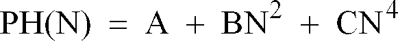
- The color cathode-ray tube according to claim 1, characterized in that said effective part of said shadow mask (24) as two long sides substantially parallel to said long axis and two short sides substantially parallel to said short axis, and a distance by which any two adjacent aperture arrays (32) are spaced apart at the long axis is equal to a distance by which said any two adjacent aperture arrays (32) are spaced apart at either long side.
- The color cathode-ray tube according to claim 1, characterized in that a distance between the aperture arrays (32) which are spaced about one-third the width W of the screen (23) from either short axis (Y) of the effective part of said shadow mask increases with the absolute value of the Y-coordinate and is represented by a fourth-degree function of the Y-coordinate so as to have a transition point in the effective part with respect to the short axis (Y) of the effective part.
- A color cathode-ray tube comprising:
electron-beam generating means (28) for generating electron beams (27R, 27G, 27B) in in-line fashion;
a panel (21) having a substantially rectangular effective part which has a curved inner surface;
a phosphor screen (23) provided on the inner surface of the effective part of said panel (21), for emitting red, green and blue light rays when excited by the electron beams generated by said electron-beam generating means (28); and
a shadow mask (24) having a curved, substantially rectangular effective part facing the phosphor screen (23) and having a number of apertures (31) for guiding the electron beams (27R, 27G, 27B) to said phosphor screen (23),
characterized in that said apertures (31) are elongated and arranged, forming a plurality of arrays (32) which extend along the short axis (Y) of the effective part and juxtaposed along the long axis (X) of the effective part and which are curved in different ways; the elongated apertures (31) are inclined at different angles to the short axis (Y) of said effective part such that in a section extending for one-fourth the width of the effective part from either short side (Y) thereof, the elongated apertures (32) located near either long side of the effective part are more inclined than those located near the long axis of the effective part; and for the apertures (31) made in a section extending for one-third the height of the effective part from either long side thereof, the angle changes from the short axis (Y) of the effective part toward either short side thereof, first increasing gradually to a maximum positive value and then decreasing to 0° or to a negative value. - The color cathode-ray tube according to claim 4, characterized in that a position each elongated aperture (31) assumes in said effective part is represented by coordinates (x, y) in a coordinate system whose origin is the center of the effective part and whose axes are the long axis X and short axis Y of the effective part, where x is a fourth-degree even function or a higher-degree even function of y.
Priority Applications (1)
| Application Number | Priority Date | Filing Date | Title |
|---|---|---|---|
| EP98121370A EP0893814B1 (en) | 1994-07-14 | 1995-07-11 | Color cathode-ray tube |
Applications Claiming Priority (6)
| Application Number | Priority Date | Filing Date | Title |
|---|---|---|---|
| JP16194294 | 1994-07-14 | ||
| JP161942/94 | 1994-07-14 | ||
| JP16194294 | 1994-07-14 | ||
| JP24256094 | 1994-10-06 | ||
| JP24256094 | 1994-10-06 | ||
| JP242560/94 | 1994-10-06 |
Related Child Applications (1)
| Application Number | Title | Priority Date | Filing Date |
|---|---|---|---|
| EP98121370.5 Division-Into | 1998-11-10 |
Publications (2)
| Publication Number | Publication Date |
|---|---|
| EP0692810A1 true EP0692810A1 (en) | 1996-01-17 |
| EP0692810B1 EP0692810B1 (en) | 2001-10-17 |
Family
ID=26487888
Family Applications (2)
| Application Number | Title | Priority Date | Filing Date |
|---|---|---|---|
| EP95110812A Expired - Lifetime EP0692810B1 (en) | 1994-07-14 | 1995-07-11 | Color cathode-ray tube |
| EP98121370A Expired - Lifetime EP0893814B1 (en) | 1994-07-14 | 1995-07-11 | Color cathode-ray tube |
Family Applications After (1)
| Application Number | Title | Priority Date | Filing Date |
|---|---|---|---|
| EP98121370A Expired - Lifetime EP0893814B1 (en) | 1994-07-14 | 1995-07-11 | Color cathode-ray tube |
Country Status (6)
| Country | Link |
|---|---|
| US (1) | US5672934A (en) |
| EP (2) | EP0692810B1 (en) |
| KR (1) | KR100190675B1 (en) |
| CN (2) | CN1108626C (en) |
| DE (2) | DE69528779T2 (en) |
| TW (1) | TW297907B (en) |
Cited By (2)
| Publication number | Priority date | Publication date | Assignee | Title |
|---|---|---|---|---|
| EP0896359A4 (en) * | 1996-12-25 | 1999-02-10 | ||
| EP1617455A1 (en) * | 2004-06-01 | 2006-01-18 | Matsushita Toshiba Picture Display Co., Ltd. | Color picture tube |
Families Citing this family (4)
| Publication number | Priority date | Publication date | Assignee | Title |
|---|---|---|---|---|
| JPH11250822A (en) | 1998-03-03 | 1999-09-17 | Toshiba Corp | Color picture tube |
| WO2004088704A1 (en) * | 2000-11-25 | 2004-10-14 | Orion Electric Co., Ltd. | Method for manufacturing a shadow -mask |
| KR100418028B1 (en) * | 2000-11-27 | 2004-02-11 | 엘지전자 주식회사 | A Color Cathode Ray Tube |
| US6784856B2 (en) * | 2001-12-13 | 2004-08-31 | International Business Machines Corp. | System and method for anti-moire display |
Citations (6)
| Publication number | Priority date | Publication date | Assignee | Title |
|---|---|---|---|---|
| US4583022A (en) * | 1984-05-31 | 1986-04-15 | Rca Corporation | Color picture tube having shadow mask with specific curvature and column aperture spacing |
| US4631441A (en) * | 1985-03-14 | 1986-12-23 | Rca Corporation | Color picture tube having improved line screen |
| US4636441A (en) | 1984-10-09 | 1987-01-13 | Bayer Aktiengesellschaft | Semi-finished products for the manufacture of printed circuit boards |
| US4691138A (en) | 1985-03-14 | 1987-09-01 | Rca Corporation | Color picture tube having shadow mask with varied aperture column spacing |
| JPH051574A (en) | 1991-06-25 | 1993-01-08 | Mazda Motor Corp | Valve timing controller of engine |
| JPH0542772A (en) | 1991-08-08 | 1993-02-23 | Tokyo Jiki Insatsu Kk | Thermal recording medium |
Family Cites Families (5)
| Publication number | Priority date | Publication date | Assignee | Title |
|---|---|---|---|---|
| JPS5244511B2 (en) * | 1972-08-30 | 1977-11-08 | ||
| NL7303077A (en) * | 1973-03-06 | 1974-09-10 | ||
| JPS59165338A (en) * | 1983-03-10 | 1984-09-18 | Toshiba Corp | Color picture tube |
| SU1461377A3 (en) * | 1984-05-25 | 1989-02-23 | Рка Корпорейшн (Фирма) | Colour kinescope |
| FR2589002B1 (en) * | 1985-10-22 | 1994-09-23 | Videocolor | COLOR TELEVISION TUBE OF THE MASK TYPE AND MANUFACTURING METHOD THEREOF |
-
1995
- 1995-07-08 TW TW084107091A patent/TW297907B/zh active
- 1995-07-11 DE DE69528779T patent/DE69528779T2/en not_active Expired - Fee Related
- 1995-07-11 EP EP95110812A patent/EP0692810B1/en not_active Expired - Lifetime
- 1995-07-11 DE DE69523225T patent/DE69523225T2/en not_active Expired - Fee Related
- 1995-07-11 EP EP98121370A patent/EP0893814B1/en not_active Expired - Lifetime
- 1995-07-13 US US08/502,174 patent/US5672934A/en not_active Expired - Fee Related
- 1995-07-14 KR KR1019950020681A patent/KR100190675B1/en not_active IP Right Cessation
- 1995-07-14 CN CN95108393A patent/CN1108626C/en not_active Expired - Fee Related
-
2000
- 2000-01-24 CN CN00101680A patent/CN1269595A/en active Pending
Patent Citations (6)
| Publication number | Priority date | Publication date | Assignee | Title |
|---|---|---|---|---|
| US4583022A (en) * | 1984-05-31 | 1986-04-15 | Rca Corporation | Color picture tube having shadow mask with specific curvature and column aperture spacing |
| US4636441A (en) | 1984-10-09 | 1987-01-13 | Bayer Aktiengesellschaft | Semi-finished products for the manufacture of printed circuit boards |
| US4631441A (en) * | 1985-03-14 | 1986-12-23 | Rca Corporation | Color picture tube having improved line screen |
| US4691138A (en) | 1985-03-14 | 1987-09-01 | Rca Corporation | Color picture tube having shadow mask with varied aperture column spacing |
| JPH051574A (en) | 1991-06-25 | 1993-01-08 | Mazda Motor Corp | Valve timing controller of engine |
| JPH0542772A (en) | 1991-08-08 | 1993-02-23 | Tokyo Jiki Insatsu Kk | Thermal recording medium |
Cited By (5)
| Publication number | Priority date | Publication date | Assignee | Title |
|---|---|---|---|---|
| EP0896359A4 (en) * | 1996-12-25 | 1999-02-10 | ||
| EP0896359A1 (en) * | 1996-12-25 | 1999-02-10 | Kabushiki Kaisha Toshiba | Color image receiving tube |
| US6204599B1 (en) | 1996-12-25 | 2001-03-20 | Kabushiki Kaisha Toshiba | Color cathode ray tube with graded shadow mask apertures |
| EP1617455A1 (en) * | 2004-06-01 | 2006-01-18 | Matsushita Toshiba Picture Display Co., Ltd. | Color picture tube |
| US7045942B2 (en) | 2004-06-01 | 2006-05-16 | Matsushita Toshiba Picture Display Co., Ltd. | Color picture tube |
Also Published As
| Publication number | Publication date |
|---|---|
| DE69528779T2 (en) | 2003-07-17 |
| CN1269595A (en) | 2000-10-11 |
| US5672934A (en) | 1997-09-30 |
| TW297907B (en) | 1997-02-11 |
| KR100190675B1 (en) | 1999-06-01 |
| DE69523225T2 (en) | 2002-06-27 |
| EP0893814A2 (en) | 1999-01-27 |
| EP0893814A3 (en) | 1999-04-07 |
| CN1135092A (en) | 1996-11-06 |
| EP0692810B1 (en) | 2001-10-17 |
| DE69528779D1 (en) | 2002-12-12 |
| DE69523225D1 (en) | 2001-11-22 |
| EP0893814B1 (en) | 2002-11-06 |
| KR960005699A (en) | 1996-02-23 |
| CN1108626C (en) | 2003-05-14 |
Similar Documents
| Publication | Publication Date | Title |
|---|---|---|
| JP3300229B2 (en) | Color picture tube with shadow mask with improved aperture spacing | |
| JPS63942A (en) | Planar shadowmask for color crt | |
| US4983879A (en) | Shadow mask type color cathode ray tube with shadow mask effective to minimize the appearance of Moire patterns | |
| EP0692810B1 (en) | Color cathode-ray tube | |
| KR100310404B1 (en) | Shadow mask for color cathode ray tube and its manufacturing method | |
| US6124668A (en) | Color cathode ray tube | |
| US4429028A (en) | Color picture tube having improved slit type shadow mask and method of making same | |
| US3003874A (en) | Optical correction in manufacture of color image reproducers | |
| US20020180331A1 (en) | Color cathode ray tube having improved color purity | |
| US4701665A (en) | Color cathode-ray tube | |
| US6803713B2 (en) | Color cathode ray tube | |
| US6614153B2 (en) | Mask for color picture tube | |
| US7019451B2 (en) | Shadow mask of color CRT | |
| KR900005932B1 (en) | Color picture tube having improved shadow mask | |
| JPS6345741A (en) | Making of color crt shadow mask, front assembly of color crt, roughly flat face plate of super high resolution color crt | |
| US6441545B1 (en) | Color cathode ray tube having particular arrangement of electron beam through hole arrays | |
| EP1306875B1 (en) | Tension mask for a cathode-ray-tube | |
| US4983995A (en) | Exposure device for forming phosphor deposited screen in in-line cathode ray tube | |
| US6294863B1 (en) | Color cathode ray tube having a shadow mask with a plurality of strip shaped reinforcing beads | |
| US6559575B1 (en) | Cathode ray tube and method of manufacturing the same, and color selecting member for cathode ray tube and method of manufacturing the same | |
| KR100545712B1 (en) | Shadow mask for color cathode ray tube | |
| JP3353582B2 (en) | Color cathode ray tube and manufacturing method thereof | |
| JP3532319B2 (en) | Color picture tube | |
| KR100205407B1 (en) | Shadow mask of cathode-ray tube | |
| US5821684A (en) | Color cathode ray tube with suppressed doming |
Legal Events
| Date | Code | Title | Description |
|---|---|---|---|
| PUAI | Public reference made under article 153(3) epc to a published international application that has entered the european phase |
Free format text: ORIGINAL CODE: 0009012 |
|
| 17P | Request for examination filed |
Effective date: 19950807 |
|
| AK | Designated contracting states |
Kind code of ref document: A1 Designated state(s): DE FR GB |
|
| 17Q | First examination report despatched |
Effective date: 19970515 |
|
| GRAG | Despatch of communication of intention to grant |
Free format text: ORIGINAL CODE: EPIDOS AGRA |
|
| GRAG | Despatch of communication of intention to grant |
Free format text: ORIGINAL CODE: EPIDOS AGRA |
|
| GRAG | Despatch of communication of intention to grant |
Free format text: ORIGINAL CODE: EPIDOS AGRA |
|
| GRAH | Despatch of communication of intention to grant a patent |
Free format text: ORIGINAL CODE: EPIDOS IGRA |
|
| GRAH | Despatch of communication of intention to grant a patent |
Free format text: ORIGINAL CODE: EPIDOS IGRA |
|
| GRAA | (expected) grant |
Free format text: ORIGINAL CODE: 0009210 |
|
| AK | Designated contracting states |
Kind code of ref document: B1 Designated state(s): DE FR GB |
|
| REF | Corresponds to: |
Ref document number: 69523225 Country of ref document: DE Date of ref document: 20011122 |
|
| REG | Reference to a national code |
Ref country code: GB Ref legal event code: IF02 |
|
| ET | Fr: translation filed | ||
| PLBE | No opposition filed within time limit |
Free format text: ORIGINAL CODE: 0009261 |
|
| STAA | Information on the status of an ep patent application or granted ep patent |
Free format text: STATUS: NO OPPOSITION FILED WITHIN TIME LIMIT |
|
| 26N | No opposition filed | ||
| PGFP | Annual fee paid to national office [announced via postgrant information from national office to epo] |
Ref country code: DE Payment date: 20070705 Year of fee payment: 13 |
|
| PGFP | Annual fee paid to national office [announced via postgrant information from national office to epo] |
Ref country code: GB Payment date: 20070711 Year of fee payment: 13 |
|
| PGFP | Annual fee paid to national office [announced via postgrant information from national office to epo] |
Ref country code: FR Payment date: 20070710 Year of fee payment: 13 |
|
| GBPC | Gb: european patent ceased through non-payment of renewal fee |
Effective date: 20080711 |
|
| PG25 | Lapsed in a contracting state [announced via postgrant information from national office to epo] |
Ref country code: DE Free format text: LAPSE BECAUSE OF NON-PAYMENT OF DUE FEES Effective date: 20090203 |
|
| REG | Reference to a national code |
Ref country code: FR Ref legal event code: ST Effective date: 20090331 |
|
| PG25 | Lapsed in a contracting state [announced via postgrant information from national office to epo] |
Ref country code: GB Free format text: LAPSE BECAUSE OF NON-PAYMENT OF DUE FEES Effective date: 20080711 |
|
| PG25 | Lapsed in a contracting state [announced via postgrant information from national office to epo] |
Ref country code: FR Free format text: LAPSE BECAUSE OF NON-PAYMENT OF DUE FEES Effective date: 20080731 |