EP0692702A1 - Infrared radiation source for a gas analyzer and a method for generating infrared radiation - Google Patents
Infrared radiation source for a gas analyzer and a method for generating infrared radiation Download PDFInfo
- Publication number
- EP0692702A1 EP0692702A1 EP95304828A EP95304828A EP0692702A1 EP 0692702 A1 EP0692702 A1 EP 0692702A1 EP 95304828 A EP95304828 A EP 95304828A EP 95304828 A EP95304828 A EP 95304828A EP 0692702 A1 EP0692702 A1 EP 0692702A1
- Authority
- EP
- European Patent Office
- Prior art keywords
- radiant
- insulation material
- thermal insulation
- radiation source
- source
- Prior art date
- Legal status (The legal status is an assumption and is not a legal conclusion. Google has not performed a legal analysis and makes no representation as to the accuracy of the status listed.)
- Granted
Links
- 230000005855 radiation Effects 0.000 title claims abstract description 100
- 238000000034 method Methods 0.000 title claims abstract description 9
- 239000012774 insulation material Substances 0.000 claims abstract description 31
- 238000005259 measurement Methods 0.000 claims abstract description 4
- 238000009413 insulation Methods 0.000 claims description 23
- 230000004907 flux Effects 0.000 claims description 12
- 239000000463 material Substances 0.000 claims description 5
- 238000010438 heat treatment Methods 0.000 claims description 4
- 230000000694 effects Effects 0.000 claims description 3
- 238000003754 machining Methods 0.000 claims description 2
- 230000000903 blocking effect Effects 0.000 claims 1
- 239000000203 mixture Substances 0.000 claims 1
- 230000003595 spectral effect Effects 0.000 description 18
- 239000007789 gas Substances 0.000 description 16
- 238000010276 construction Methods 0.000 description 12
- 238000009826 distribution Methods 0.000 description 10
- 239000000919 ceramic Substances 0.000 description 5
- 230000003287 optical effect Effects 0.000 description 5
- 229910010271 silicon carbide Inorganic materials 0.000 description 5
- HBMJWWWQQXIZIP-UHFFFAOYSA-N silicon carbide Chemical compound [Si+]#[C-] HBMJWWWQQXIZIP-UHFFFAOYSA-N 0.000 description 4
- 229920004482 WACKER® Polymers 0.000 description 3
- 238000001816 cooling Methods 0.000 description 3
- 229910000953 kanthal Inorganic materials 0.000 description 3
- PXHVJJICTQNCMI-UHFFFAOYSA-N Nickel Chemical compound [Ni] PXHVJJICTQNCMI-UHFFFAOYSA-N 0.000 description 2
- 239000004411 aluminium Substances 0.000 description 2
- 229910052782 aluminium Inorganic materials 0.000 description 2
- XAGFODPZIPBFFR-UHFFFAOYSA-N aluminium Chemical compound [Al] XAGFODPZIPBFFR-UHFFFAOYSA-N 0.000 description 2
- 238000004364 calculation method Methods 0.000 description 2
- 238000010586 diagram Methods 0.000 description 2
- 229910052751 metal Inorganic materials 0.000 description 2
- 239000002184 metal Substances 0.000 description 2
- 239000003973 paint Substances 0.000 description 2
- 239000011241 protective layer Substances 0.000 description 2
- ZSLUVFAKFWKJRC-IGMARMGPSA-N 232Th Chemical compound [232Th] ZSLUVFAKFWKJRC-IGMARMGPSA-N 0.000 description 1
- 230000005457 Black-body radiation Effects 0.000 description 1
- 229910000990 Ni alloy Inorganic materials 0.000 description 1
- 229910052776 Thorium Inorganic materials 0.000 description 1
- 238000010420 art technique Methods 0.000 description 1
- WUKWITHWXAAZEY-UHFFFAOYSA-L calcium difluoride Chemical compound [F-].[F-].[Ca+2] WUKWITHWXAAZEY-UHFFFAOYSA-L 0.000 description 1
- 229910001634 calcium fluoride Inorganic materials 0.000 description 1
- 229910010293 ceramic material Inorganic materials 0.000 description 1
- VNNRSPGTAMTISX-UHFFFAOYSA-N chromium nickel Chemical compound [Cr].[Ni] VNNRSPGTAMTISX-UHFFFAOYSA-N 0.000 description 1
- 239000011248 coating agent Substances 0.000 description 1
- 238000000576 coating method Methods 0.000 description 1
- 238000000205 computational method Methods 0.000 description 1
- 239000002826 coolant Substances 0.000 description 1
- 238000005553 drilling Methods 0.000 description 1
- -1 e.g. Substances 0.000 description 1
- 239000011521 glass Substances 0.000 description 1
- 239000011810 insulating material Substances 0.000 description 1
- 239000010410 layer Substances 0.000 description 1
- 238000004519 manufacturing process Methods 0.000 description 1
- 238000013021 overheating Methods 0.000 description 1
- 229910052594 sapphire Inorganic materials 0.000 description 1
- 239000010980 sapphire Substances 0.000 description 1
- 229910052709 silver Inorganic materials 0.000 description 1
- 239000004332 silver Substances 0.000 description 1
- XLYOFNOQVPJJNP-UHFFFAOYSA-N water Substances O XLYOFNOQVPJJNP-UHFFFAOYSA-N 0.000 description 1
- 229910052727 yttrium Inorganic materials 0.000 description 1
- VWQVUPCCIRVNHF-UHFFFAOYSA-N yttrium atom Chemical compound [Y] VWQVUPCCIRVNHF-UHFFFAOYSA-N 0.000 description 1
Images


Classifications
-
- G—PHYSICS
- G01—MEASURING; TESTING
- G01J—MEASUREMENT OF INTENSITY, VELOCITY, SPECTRAL CONTENT, POLARISATION, PHASE OR PULSE CHARACTERISTICS OF INFRARED, VISIBLE OR ULTRAVIOLET LIGHT; COLORIMETRY; RADIATION PYROMETRY
- G01J3/00—Spectrometry; Spectrophotometry; Monochromators; Measuring colours
- G01J3/02—Details
- G01J3/10—Arrangements of light sources specially adapted for spectrometry or colorimetry
- G01J3/108—Arrangements of light sources specially adapted for spectrometry or colorimetry for measurement in the infrared range
Definitions
- the invention is related to an infrared radiation source according to the preamble of claim 1 for a gas analyzer.
- the invention also concerns a method for generating infrared radiation.
- Infrared radiation in gas analyzers is typically generated using a thermal radiation source whose surface is heated to such a sufficiently elevated temperature that the surface in accordance with Planck's radiation law and the spectral emissivity of the surface emits the required amount of radiant power at the measurement wavelengths employed in the gas analyzer.
- the spectral emissivity of the radiating surface in the infrared source should be maximized for the wavelengths used in the analyzer.
- the area of the radiating surface and its temperature are selected according to the operating principle and optical construction of the analyzer. If the source must desirably have a very narrow-angle collimated beam, the radiant element shall have a small area and it must operate at a high temperature (cf. US Pat. No. 4,449,382/Vincent, according to which: element diameter 1.57 mm and temperature 2000 K). If a collimated beam is not necessary, an emissive surface of larger area and lower operating temperature can be used.
- Radiation sources can be complemented with optical systems such as mirrors or lenses employed to collect the radiation and direct it via the sample chamber of the gas analyzer to the detectors whose output signals are then processed by computational methods to determine the concentrations of the gases to be measured.
- This kind of arrangement has the shortcoming that the radiation source must be small and easy to align accurately.
- a high operating temperature must be used in the small and easy-to-align radiation source which is coupled to the radiation-collecting optical system.
- Such a high operating temperature limits the selection of materials suitable for use in the radiation source, and particularly, the life of the radiation source.
- the optical radiation-collecting system degrades the thermal insulation level of the radiation source.
- the construction of the thermal radiation source can be, e.g., the Nernst glower, an incandescent filament wound onto a ceramic body, a silicon carbide glower or a glower spiral made from a suitable metal wire.
- Commercially available are also so-called black-body radiation sources principally intended for laboratory use and based on a cavity of special construction which is surrounded by an effective thermal insulation and kept very accurately at a constant temperature, whereby the cavity emits a spectral distribution accurately obeying Planck's radiation law, the effective spectral emissivity of the cavity being close to the theoretical maximum value (that is, 1.0).
- a benefit of the incandescent-wire-heated cavity radiator disclosed in cited US Pat. No. 4,449,382 is its high effective spectral emissivity, mechanical strength and a construction facilitating effective thermal insulation, whereby a good efficiency results.
- a disadvantage lies in that the radiant flux of the hottest part of the radiation source, namely the radiation emitted by the incandescent wire, cannot be utilized.
- the Nernst glower is a bar or tube made of yttrium, thorium or ceramic material heated by electric current flowing through it.
- a disadvantage of the Nernst glower is that the electrical resistance of the glower at room temperature is so high that at start-up the glower must be heated by an external auxiliary heater to a value close to its operating temperature.
- the glower rod or tube has a low emissivity, typically varying in the range 0.15-0.75 over the wavelength range 3-20 ⁇ m.
- resistive heater wire wound inside a ceramic body is capable of self-starting without heat applied from its exterior, its shortcoming is the same as that of the Nernst glower, namely the low spectral emissivity of the ceramic radiant surface.
- a silicon carbide glower is frequently used as the radiation source in, e.g., infrared spectrometers.
- This type of glower comprises a silicon carbide bar having metallic electrode end caps conventionally made of silver. Electric current used for heating the glower passes through the silicon carbide body heating it up.
- a disadvantage of this radiation source is that water cooling is usually necessary to avoid overheating of the electrodes. Such cooling degrades the efficiency of the source and requires a complicated coolant circulation system.
- a coiled incandescent filament element made from chromium-nickel alloy wire may also be used as a radiation source with an emissivity exceeding 0.9 over a wide wavelength range.
- the coiled incandescent filament typically needs to be supported by a ceramic body which conducts heat away from the radiator proper, thus lowering its spectral efficiency.
- This type of radiation source is disclosed in the publication WO 93/09412 (Herrera, Braig, Goldberger).
- the goal of the invention is accomplished by at least partially surrounding the radiation source by a thermal insulation material whose thermal conductivity is selected low, typically lower than 0.1 W/(m ⁇ K) and by making the emissivity of the background surrounding the radiation source high at the operating temperature, typically higher than 0.5.
- the radiation source proper is placed close to the thermal insulation material.
- the infrared radiation source for a gas analyzer is characterized by what is stated in the characterizing part of claim 1.
- the invention offers significant benefits.
- the gas analyzer radiation source according to the invention is suited for use without high-efficiency collimating optics, and owing to its good thermal insulation level and cavity construction, it achieves high spectral efficiency.
- An additional factor improving the spectral efficiency is that a significant portion of the radiation emitted by the radiant surface impinges on the radiant element thus increasing its temperature.
- the radiation source according to the invention has a large radiant surface, the operating temperature of the source can be kept sufficiently low to achieve a very long life of the source.
- the power consumption of the lamp may be reduced and simultaneously the spatial emission pattern of the lamp can be made insensitive to variations in the mechanical dimensions of the source.
- An additional benefit of essential importance offered by the present radiation source construction is that the mechanical alignment of the radiant element within the insulating material cavity has no significant effect on the radiant flux of the source.
- the infrared radiation source according to the invention emits radiation from both the radiant element and the radiant surface surrounding it, the radiant flux of the infrared radiation source is not particularly sensitive to the location of theradiant element within the surrounding cavity. Consequently, the source construction according to the invention does not require accurate alignment of the radiant element.
- focusing reflective surfaces are employed requiring minimum emissivity, typically less than 0.5. Due to the use of such focusing reflective surfaces, these embodiments require an accurate alignment of the radiant element at its correct place.
- the infrared radiation source according to the invention may be classified into the category of radiation sources having a relatively large emitting area and a relatively low operating temperature as the source typically has an emitting area of approx. 10 mm and an operating temperature of approx. 1200 K.
- the radiation source according to the invention is diagrammatically illustrated in Figs. 1 - 3.
- the infrared radiation source comprises a radiant element 1, a radiant surface 11 at least partially surrounding the radiant element and a thermal insulation as well as a cavity 7 fabricated in the thermal insulation, whereby the opening of the cavity serves as an aperture for the emitted infrared radiation.
- the radiant element 1 is heated by external energy passed thereto and functions as a source of infrared radiation whose characteristics are determined by the Planck radiation law. A portion of the radiation emitted by the element can reach the detector of the analyzer via the aperture of the cavity 7 and the sample chamber.
- a significant portion, or, preferably, most of the radiation emitted by the radiant element 1 is incident on the radiant surface 11.
- the temperature of the radiant surface 11 is substantially elevated, whereby the surface starts to emit infrared radiation in accordance with Planck's radiation law, a portion of which can reach the gas analyzer via the aperture 7.
- Planck's radiation law a portion of which can reach the gas analyzer via the aperture 7.
- its emissivity should be maximally high, preferably higher than 0.5.
- Fig. 2 provides a diagrammatic illustration of also the sample chamber 9 and the infrared detector 10 of the gas analyzer, although these components are not directly associated with infrared radiation source proper.
- the part marked with dashed lines represents that portion of the infrared radiation source according to the invention which comprises the radiant element 1 and the radiant surface 11 and constitutes the radiation emitting portion of the infrared radiation source, the rays of infrared radiation being incident on the detector 10 from this portion.
- This geometry has a remarkable benefit in that the output flux of the radiation source is not particularly sensitive to the location of the coiled heater element 1. Hence, the alignment of the coiled heater element 1 is relatively noncritical.
- the infrared radiation source is shown as viewed from the detector.
- the inner surface of the thermal insulation is adapted as close as possible to the outer surface of the coiled heater element in order to maximize the heat flow to the inner surface of the insulation.
- the distance between the coiled heater element 1 and the inner surface of the thermal insulation 11 is advantageously made as small as is feasible within the manufacturing tolerances.
- the coiled heater element 1 can be manufactured directly adhering to the inner surface of the insulation 11, whereby it will be mechanically supported.
- adapting the inner surface of the insulation 11 very close to the outer surface of the coiled heater element 1, or even in contact with the element is advantageous as the thickness of the thermal insulation can thus be maximized within the constraints of the available space.
- the dotted line in the graph represents the spectral distribution of the coiled heater element operating at 1100 K and the dash-dotted line represents the spectral distribution of the radiant surface operating at 900 K, while the continuous line shows the actual spectral distribution of the source over the wavelength range 7 - 12 ⁇ m, this spectral distribution being formed as the sum of the spectral distributions of the coiled heater element 1 and the radiant surface 11.
- Etot( ⁇ ) E1( ⁇ ) + E2( ⁇ )
- the calculations are carried out with the assumption that the emissivity of the coiled heater element 1 and the radiant surface 11 is 0.9 and that the areas of the radiant surface 11 and the coiled heater element 1 projected toward the detector 10 are equal.
- the diagram shows that at 8.5 ⁇ m wavelength, for instance, approximately 40 % of the output flux of the infrared source is emitted from the radiant surface 11.
- the practical embodiment of the radiation source illustrated therein is comprised of an air-core coiled heater element 1, a radiant surface 11, electrodes 2 and 3 for passing electric current through the coiled heater element 1, a mounting collar 4, a thermal insulation 5, a body piece 6, a cavity 7 and a window 8 mounted on the body piece 6 at the aperture of the cavity 7.
- the coiled heater element 1 acting as the radiant element may be made from, e.g., dia. 0.28 mm resistance wire type AF manufactured by Kanthal AB.
- the coiled heater element 1 may have a diameter of, e.g., 3.5 mm comprising 15 turns of the resistance wire.
- the electric current is passed to the radiant element 1 by means of electrodes 2 and 3.
- the electrodes 2 and 3 may be of the same material as the coiled heater element 1 itself, or to minimize resistive losses, they may be made from, e.g., dia. 0.4 mm nickel wire, or to reduce both resistive and thermal conduction losses, they may alternatively be made from dia. 0.4 - 0.7 mm Kanthal AF wire. Further, it is possible to have one electrode, e.g., electrode 2 made from Kanthal AF wire while the other electrode 3 is made from nickel wire.
- the mounting collar 4 may be a glass piece adhesive-bonded or fused to the electrodes 2 and 3, or alternatively, it may be an aluminium piece adhesive-bonded to the electrodes 2 and 3.
- the thermal insulation 5 shall be made from a material whose thermal conductivity at the operating temperature of the coiled heater element 1 is the lowest possible.
- the emissivity of the radiant surface 11 over the operating wavelength band of the radiation source shall be as high as possible. In practice it has been found that the thermal insulation becomes disadvantageously thick if the thermal conductivity of the wall of the radiant surface 11 exceeds 0.1 W/(m ⁇ K) and that the radiation emitted by the inner surface of the thermal insulation has a minor role in the total spectral distribution if the emissivity of the surface is below 0.5.
- a suitable insulation material is, e.g., type WDS1000 manufactured by Wacker Chemie GmbH and specified to have a thermal conductivity of 0.05 W/(m ⁇ K) and an emissivity of approx.
- the coiled heater element 1 When the coiled heater element 1 is surrounded from as many angles as possible by the above-mentioned insulation material, the coiled element can be heated to the required operating temperature (approx. 900 °C) using a relatively low electric input power.
- a cavity 7 and a feed-through hole 13 for the electrodes 2 and 3 are fabricated in the insulation material block 5 by drilling.
- the radiant surface 11 may be formed by a layer of heat-resistant paint, e.g., type QF 180 manufactured by The Carborundum Company, Ltd., applied onto the inner surface of the thermal insulation block 5.
- the emissivity of such a coating is approx. 9.0 over the 8 - 9 ⁇ m wavelength band.
- the emissivity of the radiant surface must be greater than 0.5 to make the radiation emitted by the surface form a significant portion (more than 20 %) of the total radiant flux of the infrared source.
- the body piece 6 can be made from a metal, e.g., aluminium, whereby its cooling is easy to arrange.
- the body piece 6 is provided with an opening 12 with dimensions equal to the cross section of the cavity 7, whereby the emitted radiation can pass through the opening and the window 8 to the gas analyzer.
- the window 8 is made from a material transparent to infrared radiation such as sapphire or calcium fluoride depending on the wavelength passband required in the gas analyzer.
- the window 8 may also be an optical filter optimized for the gas analyzer, whereby the filter passes only the desired wavelength band required in the gas analyzer and reflects infrared radiation at other wavelengths back to the cavity 7.
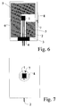
- FIG. 6 an embodiment is illustrated having the insulation material 5 (Wacker WDS1000) acting as both the radiant surface and the insulation material, whereby no separate radiant surface need be fabricated.
- the construction of the radiation source shown in Fig. 6 is shown in a front view as seen from the gas analyzer side.
- the infrared radiation can pass from both the coiled heater element 1 and the inner surface of the insulation material block 5 heated by the coiled heater element through the aperture 7 and the window 8 to the gas analyzer.
- FIG. 8 an embodiment according to the invention is shown having the insulation material block 5 (Wacker WDS100) shaped by laser machining during which the insulation material 5 is heated very intensely at the machined point, whereby its top surface is burnt forming a mechanically durable and nondusting protective layer.
- the radiant surface 11 is formed by applying a coat of the heat-resistant paint type QF 180.
- the thermal resistance R TH of the insulation material 5 is advantageously greater than 200 K/W.
- the radiant surface 11 may also be an independent structure adapted between the radiant element 1 and the insulation 5.
- the radiation emitted by the radiant surface 11 forms at least 20 % of the total infrared radiant flux of the infrared radiation source.
- the proportion of the radiant surface 11 in the total radiant flux is greater than 40 %.
Landscapes
- Physics & Mathematics (AREA)
- Spectroscopy & Molecular Physics (AREA)
- General Physics & Mathematics (AREA)
- Investigating Or Analysing Materials By Optical Means (AREA)
- Resistance Heating (AREA)
Abstract
Description
- The invention is related to an infrared radiation source according to the preamble of claim 1 for a gas analyzer.
- The invention also concerns a method for generating infrared radiation.
- Infrared radiation in gas analyzers is typically generated using a thermal radiation source whose surface is heated to such a sufficiently elevated temperature that the surface in accordance with Planck's radiation law and the spectral emissivity of the surface emits the required amount of radiant power at the measurement wavelengths employed in the gas analyzer.
- The spectral emissivity of the radiating surface in the infrared source should be maximized for the wavelengths used in the analyzer. The area of the radiating surface and its temperature are selected according to the operating principle and optical construction of the analyzer. If the source must desirably have a very narrow-angle collimated beam, the radiant element shall have a small area and it must operate at a high temperature (cf. US Pat. No. 4,449,382/Vincent, according to which: element diameter 1.57 mm and temperature 2000 K). If a collimated beam is not necessary, an emissive surface of larger area and lower operating temperature can be used.
- Radiation sources can be complemented with optical systems such as mirrors or lenses employed to collect the radiation and direct it via the sample chamber of the gas analyzer to the detectors whose output signals are then processed by computational methods to determine the concentrations of the gases to be measured. This kind of arrangement has the shortcoming that the radiation source must be small and easy to align accurately. To achieve a sufficiently intense radiant flux, a high operating temperature must be used in the small and easy-to-align radiation source which is coupled to the radiation-collecting optical system. Such a high operating temperature limits the selection of materials suitable for use in the radiation source, and particularly, the life of the radiation source. Furthermore, the optical radiation-collecting system degrades the thermal insulation level of the radiation source.
- The construction of the thermal radiation source can be, e.g., the Nernst glower, an incandescent filament wound onto a ceramic body, a silicon carbide glower or a glower spiral made from a suitable metal wire. Commercially available are also so-called black-body radiation sources principally intended for laboratory use and based on a cavity of special construction which is surrounded by an effective thermal insulation and kept very accurately at a constant temperature, whereby the cavity emits a spectral distribution accurately obeying Planck's radiation law, the effective spectral emissivity of the cavity being close to the theoretical maximum value (that is, 1.0). Cited US Pat. No. 4,449,382 (Vincent) discloses an infrared radiation source which combines some benefits of the incandescent wire radiator and the laboratory-level Planck radiator. According to the cited patent application, the radiation source is formed by a cavity drilled in a ceramic rod which is heated by means of an incandescent wire placed on the outer surface of the rod.
- A benefit of the incandescent-wire-heated cavity radiator disclosed in cited US Pat. No. 4,449,382 is its high effective spectral emissivity, mechanical strength and a construction facilitating effective thermal insulation, whereby a good efficiency results. A disadvantage lies in that the radiant flux of the hottest part of the radiation source, namely the radiation emitted by the incandescent wire, cannot be utilized.
- The Nernst glower is a bar or tube made of yttrium, thorium or ceramic material heated by electric current flowing through it. A disadvantage of the Nernst glower is that the electrical resistance of the glower at room temperature is so high that at start-up the glower must be heated by an external auxiliary heater to a value close to its operating temperature. Furthermore, the glower rod or tube has a low emissivity, typically varying in the range 0.15-0.75 over the wavelength range 3-20 µm.
- While a resistive heater wire wound inside a ceramic body is capable of self-starting without heat applied from its exterior, its shortcoming is the same as that of the Nernst glower, namely the low spectral emissivity of the ceramic radiant surface.
- A silicon carbide glower is frequently used as the radiation source in, e.g., infrared spectrometers. This type of glower comprises a silicon carbide bar having metallic electrode end caps conventionally made of silver. Electric current used for heating the glower passes through the silicon carbide body heating it up. A disadvantage of this radiation source is that water cooling is usually necessary to avoid overheating of the electrodes. Such cooling degrades the efficiency of the source and requires a complicated coolant circulation system.
- A coiled incandescent filament element made from chromium-nickel alloy wire may also be used as a radiation source with an emissivity exceeding 0.9 over a wide wavelength range. The coiled incandescent filament typically needs to be supported by a ceramic body which conducts heat away from the radiator proper, thus lowering its spectral efficiency. This type of radiation source is disclosed in the publication WO 93/09412 (Herrera, Braig, Goldberger).
- It is an object of the present invention to overcome the drawbacks of the above-described prior-art techniques and to achieve an entirely novel type of infrared radiation source for a gas analyzer and a method for generating infrared radiation.
- The goal of the invention is accomplished by at least partially surrounding the radiation source by a thermal insulation material whose thermal conductivity is selected low, typically lower than 0.1 W/(m·K) and by making the emissivity of the background surrounding the radiation source high at the operating temperature, typically higher than 0.5. In an advantageous embodiment of the invention the radiation source proper is placed close to the thermal insulation material.
- More specifically, the infrared radiation source for a gas analyzer according to the invention is characterized by what is stated in the characterizing part of claim 1.
- Furthermore, the method according to the invention is characterized by what is stated in the characterizing part of
claim 12. - The invention offers significant benefits.
- The gas analyzer radiation source according to the invention is suited for use without high-efficiency collimating optics, and owing to its good thermal insulation level and cavity construction, it achieves high spectral efficiency. An additional factor improving the spectral efficiency is that a significant portion of the radiation emitted by the radiant surface impinges on the radiant element thus increasing its temperature. As the radiation source according to the invention has a large radiant surface, the operating temperature of the source can be kept sufficiently low to achieve a very long life of the source. By virtue of the invention, the power consumption of the lamp may be reduced and simultaneously the spatial emission pattern of the lamp can be made insensitive to variations in the mechanical dimensions of the source. An additional benefit of essential importance offered by the present radiation source construction is that the mechanical alignment of the radiant element within the insulating material cavity has no significant effect on the radiant flux of the source. As the infrared radiation source according to the invention emits radiation from both the radiant element and the radiant surface surrounding it, the radiant flux of the infrared radiation source is not particularly sensitive to the location of theradiant element within the surrounding cavity. Consequently, the source construction according to the invention does not require accurate alignment of the radiant element. In the contrasting constructions of the prior art, focusing reflective surfaces are employed requiring minimum emissivity, typically less than 0.5. Due to the use of such focusing reflective surfaces, these embodiments require an accurate alignment of the radiant element at its correct place.
- In the following, the invention will be examined in more detail by means of exemplifying embodiments with reference to the attached drawings, in which:
- Figure 1 is a longitudinally sectional side view of an infrared radiation source according to the invention;
- Figure 2 is a longitudinally sectional side view of the infrared radiation source construction illustrated in Fig. 1 complemented with a measurement channel and a detector;
- Figure 3 is a front view of the aperture in the infrared radiation source constructions illustrated in Figs. 1 and 2;
- Figure 4 is a graph elucidating the effect of the construction according to the invention on the amount of infrared radiation flux as a function of the wavelength;
- Figure 5 is a side view of the infrared radiation source illustrated in Fig. 1 complemented with a body structure and a feed arrangement for the electrical heating current;
- Figure 6 is a longitudinally sectional side view of another embodiment of the infrared radiation source according to the invention;
- Figure 7 is a front view of the infrared radiation source illustrated in Fig. 6; and
- Figure 8 is a longitudinally sectional side view of a third embodiment of the infrared radiation source according to the invention;
- Obviously, the infrared radiation source according to the invention may be classified into the category of radiation sources having a relatively large emitting area and a relatively low operating temperature as the source typically has an emitting area of approx. 10 mm and an operating temperature of approx. 1200 K.
- The radiation source according to the invention is diagrammatically illustrated in Figs. 1 - 3.
- Referring to the diagrams, the infrared radiation source comprises a radiant element 1, a
radiant surface 11 at least partially surrounding the radiant element and a thermal insulation as well as acavity 7 fabricated in the thermal insulation, whereby the opening of the cavity serves as an aperture for the emitted infrared radiation. - The radiant element 1 is heated by external energy passed thereto and functions as a source of infrared radiation whose characteristics are determined by the Planck radiation law. A portion of the radiation emitted by the element can reach the detector of the analyzer via the aperture of the
cavity 7 and the sample chamber. - A significant portion, or, preferably, most of the radiation emitted by the radiant element 1 is incident on the
radiant surface 11. As thethermal insulation 5 permits only a minimal heat loss from the interior of the radiation source to the environment, the temperature of theradiant surface 11 is substantially elevated, whereby the surface starts to emit infrared radiation in accordance with Planck's radiation law, a portion of which can reach the gas analyzer via theaperture 7. To make the radiant surface act as an effective infrared radiator, its emissivity should be maximally high, preferably higher than 0.5. - Fig. 2 provides a diagrammatic illustration of also the
sample chamber 9 and theinfrared detector 10 of the gas analyzer, although these components are not directly associated with infrared radiation source proper. Referring to Fig. 2, the part marked with dashed lines represents that portion of the infrared radiation source according to the invention which comprises the radiant element 1 and theradiant surface 11 and constitutes the radiation emitting portion of the infrared radiation source, the rays of infrared radiation being incident on thedetector 10 from this portion. This geometry has a remarkable benefit in that the output flux of the radiation source is not particularly sensitive to the location of the coiled heater element 1. Hence, the alignment of the coiled heater element 1 is relatively noncritical. - Referring to Fig. 3, the infrared radiation source is shown as viewed from the detector.
- In the embodiment according to the invention, the inner surface of the thermal insulation is adapted as close as possible to the outer surface of the coiled heater element in order to maximize the heat flow to the inner surface of the insulation. The distance between the coiled heater element 1 and the inner surface of the
thermal insulation 11 is advantageously made as small as is feasible within the manufacturing tolerances. Alternatively, the coiled heater element 1 can be manufactured directly adhering to the inner surface of theinsulation 11, whereby it will be mechanically supported. Furthermore, adapting the inner surface of theinsulation 11 very close to the outer surface of the coiled heater element 1, or even in contact with the element, is advantageous as the thickness of the thermal insulation can thus be maximized within the constraints of the available space. - Referring to Fig. 4, the dotted line in the graph represents the spectral distribution of the coiled heater element operating at 1100 K and the dash-dotted line represents the spectral distribution of the radiant surface operating at 900 K, while the continuous line shows the actual spectral distribution of the source over the wavelength range 7 - 12 µm, this spectral distribution being formed as the sum of the spectral distributions of the coiled heater element 1 and the
radiant surface 11. - The curves plotted in Fig. 4 are based on the following calculations:
h = 6.6256·10⁻³⁴ c = 2.2979·10⁸ k = 1.3805·10⁻³
C₁ = 8·π·h·c C₁ = 4.992·10⁻⁴
C₂ = h·c/k C₂ = 0.014 - Emission spectral distribution E1 of the coiled heater element 1:

- Emission spectral distribution E2 of the thermal insulation:

- Total spectral distribution Etot: Etot(λ) = E1(λ) + E2(λ)
- The calculations are carried out with the assumption that the emissivity of the coiled heater element 1 and the
radiant surface 11 is 0.9 and that the areas of theradiant surface 11 and the coiled heater element 1 projected toward thedetector 10 are equal. The diagram shows that at 8.5 µm wavelength, for instance, approximately 40 % of the output flux of the infrared source is emitted from theradiant surface 11. - Referring to Fig. 5, the practical embodiment of the radiation source illustrated therein is comprised of an air-core coiled heater element 1, a
radiant surface 11,electrodes collar 4, athermal insulation 5, abody piece 6, acavity 7 and awindow 8 mounted on thebody piece 6 at the aperture of thecavity 7. - In a preferred embodiment of the invention, the coiled heater element 1 acting as the radiant element may be made from, e.g., dia. 0.28 mm resistance wire type AF manufactured by Kanthal AB. The coiled heater element 1 may have a diameter of, e.g., 3.5 mm comprising 15 turns of the resistance wire.
- The electric current is passed to the radiant element 1 by means of
electrodes electrodes electrode 2 made from Kanthal AF wire while theother electrode 3 is made from nickel wire. - The mounting
collar 4 may be a glass piece adhesive-bonded or fused to theelectrodes electrodes - The
thermal insulation 5 shall be made from a material whose thermal conductivity at the operating temperature of the coiled heater element 1 is the lowest possible. The emissivity of theradiant surface 11 over the operating wavelength band of the radiation source shall be as high as possible. In practice it has been found that the thermal insulation becomes disadvantageously thick if the thermal conductivity of the wall of theradiant surface 11 exceeds 0.1 W/(m·K) and that the radiation emitted by the inner surface of the thermal insulation has a minor role in the total spectral distribution if the emissivity of the surface is below 0.5. A suitable insulation material is, e.g., type WDS1000 manufactured by Wacker Chemie GmbH and specified to have a thermal conductivity of 0.05 W/(m·K) and an emissivity of approx. 0.9 at 900 °C. When the coiled heater element 1 is surrounded from as many angles as possible by the above-mentioned insulation material, the coiled element can be heated to the required operating temperature (approx. 900 °C) using a relatively low electric input power. Acavity 7 and a feed-throughhole 13 for theelectrodes insulation material block 5 by drilling. - The
radiant surface 11 may be formed by a layer of heat-resistant paint, e.g., type QF 180 manufactured by The Carborundum Company, Ltd., applied onto the inner surface of thethermal insulation block 5. The emissivity of such a coating is approx. 9.0 over the 8 - 9 µm wavelength band. On the basis of the graph plotted in Fig. 4 it can be said that the emissivity of the radiant surface must be greater than 0.5 to make the radiation emitted by the surface form a significant portion (more than 20 %) of the total radiant flux of the infrared source. - The
body piece 6 can be made from a metal, e.g., aluminium, whereby its cooling is easy to arrange. Thebody piece 6 is provided with anopening 12 with dimensions equal to the cross section of thecavity 7, whereby the emitted radiation can pass through the opening and thewindow 8 to the gas analyzer. - The
window 8 is made from a material transparent to infrared radiation such as sapphire or calcium fluoride depending on the wavelength passband required in the gas analyzer. Thewindow 8 may also be an optical filter optimized for the gas analyzer, whereby the filter passes only the desired wavelength band required in the gas analyzer and reflects infrared radiation at other wavelengths back to thecavity 7. - Referring to Fig. 6, an embodiment is illustrated having the insulation material 5 (Wacker WDS1000) acting as both the radiant surface and the insulation material, whereby no separate radiant surface need be fabricated.
- Referring to Fig. 7, the construction of the radiation source shown in Fig. 6 is shown in a front view as seen from the gas analyzer side. In the radiation source according to the invention the infrared radiation can pass from both the coiled heater element 1 and the inner surface of the
insulation material block 5 heated by the coiled heater element through theaperture 7 and thewindow 8 to the gas analyzer. - Referring to Fig. 8, an embodiment according to the invention is shown having the insulation material block 5 (Wacker WDS100) shaped by laser machining during which the
insulation material 5 is heated very intensely at the machined point, whereby its top surface is burnt forming a mechanically durable and nondusting protective layer. As the emissivity of such a protective layer is low, theradiant surface 11 is formed by applying a coat of the heat-resistant paint type QF 180. - According to a preferred embodiment of the invention, the thermal resistance RTH of the
insulation material 5 is advantageously greater than 200 K/W. In the context of this text the term thermal resistance is defined as the property
where - L
- = thickness of insulation
- S
- = thermal conductivity, and
- A
- = surface area of insulation.
- The
radiant surface 11 may also be an independent structure adapted between the radiant element 1 and theinsulation 5. - According to the invention, the radiation emitted by the
radiant surface 11 forms at least 20 % of the total infrared radiant flux of the infrared radiation source. In a preferred embodiment of the invention, the proportion of theradiant surface 11 in the total radiant flux is greater than 40 %.
Claims (15)
- An infrared radiation source for a gas analyzer, said source comprising- a radiant element (1) suited for emitting radiation via a gas mixture to be analyzed to a detector (10),- elements (2, 3) for passing electric energy to said radiant element (1), and- insulation material (5) adapted to at least partially enclose said radiant element without, however, blocking the path of radiation from the element to the detector (10),characterized in that
- a radiant surface (11) is adapted in close proximity to said radiant element (1) to which surface a heating effect is imposed by the radiant element (1), whereby the radiation emitted by the surface comprises at least 20 % of the total infrared radiant output flux of the infrared radiation source. - A radiation source as defined in claim 1, characterized in that the emissivity of the radiant surface (11) adapted in close proximity to the radiant element is greater than 0.5 at the operating temperature of the source.
- A radiation source as defined in claim 1 or 2, having the radiant element (1) formed by a coiled incandescent filament, characterized in that the thermal conductivity of the thermal insulation material (5) at the operating temperature of the source is lower than 0.1 W/(m·K)
- A radiation source as defined in any foregoing claim, characterized in that the thermal conductivity of the thermal insulation material (5) at a temperature of 900 °C is maximally approx. 0.05 W/(m·K).
- A radiation source as defined in any foregoing claim, characterized in that the emissivity of the thermal insulation material (5) at the temperature of 900 °C is at least 0.9.
- A radiation source as defined in claim 1, characterized in that the radiant element (1) is adapted very close to inner surface of the thermal insulation material (5).
- A radiation source as defined in claim 1, charcterized in that the thermal insulation material (5) is fabricated by means of laser machining in order to achieve a hard, thin structure of the cutting surface.
- A radiation source as defined in claim 1, characterized in that a radiant surface (11) of high emissivity is formed between the thermal insulation material (5) and the radiant element (1).
- A radiation source as defined in any foregoing claim, characterized in that the thermal insulation material (5) functions as both the thermal insulation and the radiant surface.
- A radiation source as defined in any foregoing claim, characterized in that the thermal insulation material (5) and the radiant surface (11) are made from different materials.
- A radiation source as defined in any foregoing claim, characterized in that the radiant surface (11) heated by means of the radiant element (1) emits infrared radiation, whereby the contribution of the radiant surface in the total radiant output flux of the source is at least 40 %.
- A method of generating infrared radiation, in which method energy is fed to a radiant element (1) at least partially enclosed by a thermal insulation material (5),
characterized in that
- said radiant element (1) is adapted in close proximity to such a thermal insulation material (5) whose thermal conductivity in the vicinity of the radiant element (1) is low at the operating temperature of the source and the emissivity of the radiant surface (11) adapted in close proximity to the radiant element (1) is greater than 0.5 at the operating temperature of the source. - A method as defined in claim 12, characterized in that a specific radiant surface (11) is formed between the thermal insulation material (5) and the radiant element (1).
- A method as defined in claim 12, characterized in that radiation is generated principally over the wavelength range of 7 - 12 µm.
- An infrared radiation source for a gas analyzer, said source comprising- a thermal insulation material (5),- a radiant element (1) adapted in the interior of said thermal insulation material (5),- elements (2, 3) for feeding electric energy to said radiant element (1), and- a channel (7) formed in said thermal insulation material (5) in order to pass the radiation generated by said radiant element (1) to the gas under measurement,characterized in that
- at least the thermal insulation material (5) adapted in close proximity to the radiant element (1) has a low thermal conductivity at the operating temperature of the source and the emissivity of the radiant surface (11) adapted in close proximity to the radiant element (1) is greater than 0.5 at the operating temperature of the source.
Applications Claiming Priority (2)
| Application Number | Priority Date | Filing Date | Title |
|---|---|---|---|
| FI943305A FI97082C (en) | 1994-07-11 | 1994-07-11 | Infrared source of the gas analyzer and a method for generating infrared radiation |
| FI943305 | 1994-07-11 |
Publications (2)
| Publication Number | Publication Date |
|---|---|
| EP0692702A1 true EP0692702A1 (en) | 1996-01-17 |
| EP0692702B1 EP0692702B1 (en) | 2001-04-18 |
Family
ID=8541088
Family Applications (1)
| Application Number | Title | Priority Date | Filing Date |
|---|---|---|---|
| EP95304828A Expired - Lifetime EP0692702B1 (en) | 1994-07-11 | 1995-07-11 | Infrared radiation source for a gas analyzer and a method for generating infrared radiation |
Country Status (4)
| Country | Link |
|---|---|
| US (1) | US5747820A (en) |
| EP (1) | EP0692702B1 (en) |
| DE (1) | DE69520710T2 (en) |
| FI (1) | FI97082C (en) |
Cited By (2)
| Publication number | Priority date | Publication date | Assignee | Title |
|---|---|---|---|---|
| WO2000004350A2 (en) * | 1998-07-14 | 2000-01-27 | Simrad Optronics Asa | Radiation source |
| EP1347290A1 (en) * | 2002-03-22 | 2003-09-24 | Instrumentarium Corporation | Gas analyzer using thermal detectors |
Families Citing this family (3)
| Publication number | Priority date | Publication date | Assignee | Title |
|---|---|---|---|---|
| US7119904B2 (en) * | 2004-01-13 | 2006-10-10 | Thermo Electron Scientific Instruments Corporation | Stabilized infrared source for infrared spectrometers |
| US8975604B2 (en) * | 2009-09-18 | 2015-03-10 | Thermo Electron Scientific Instruments Llc | Emissivity enhanced mid IR source |
| US10466174B2 (en) * | 2016-12-13 | 2019-11-05 | Infineon Technologies Ag | Gas analyzer including a radiation source comprising a black-body radiator with at least one through-hole and a collimator |
Citations (5)
| Publication number | Priority date | Publication date | Assignee | Title |
|---|---|---|---|---|
| EP0106431A2 (en) * | 1982-10-18 | 1984-04-25 | Hewlett-Packard Company | Infrared source element |
| US4449382A (en) | 1981-08-20 | 1984-05-22 | Morton Jablin | Warp knitting machine equipped with latch-type needles |
| DE3618690A1 (en) * | 1985-06-06 | 1986-12-11 | Horiba Ltd., Kyoto | Radiation source for an infrared gas analyser |
| WO1993009412A1 (en) * | 1991-10-28 | 1993-05-13 | Critikon, Inc. | Regulated infrared source |
| EP0577261A2 (en) * | 1992-07-01 | 1994-01-05 | Nicolet Instrument Corporation | High efficiency infrared source |
Family Cites Families (7)
| Publication number | Priority date | Publication date | Assignee | Title |
|---|---|---|---|---|
| US4673031A (en) * | 1983-11-01 | 1987-06-16 | Sundstrand Corporation | Variable speed integrator |
| FR2623297B1 (en) * | 1987-11-13 | 1991-09-27 | Cit Alcatel | COUPLING DEVICE BETWEEN AN OPTICAL FIBER AND AN OPTOELECTRONIC COMPONENT |
| JP2826337B2 (en) * | 1988-04-12 | 1998-11-18 | シチズン時計株式会社 | Radiation thermometer |
| US5059397A (en) * | 1989-02-15 | 1991-10-22 | Watlow/Winona, Inc. | Gas detector system |
| JPH0356831A (en) * | 1989-07-25 | 1991-03-12 | Fujitsu Ltd | Cooling type infrared detection device |
| BE1003409A6 (en) * | 1989-09-13 | 1992-03-17 | Daele Marleen Van | Slab. |
| US5479025A (en) * | 1994-11-18 | 1995-12-26 | Hughes Aircraft Company | Boresight thermal reference source |
-
1994
- 1994-07-11 FI FI943305A patent/FI97082C/en active IP Right Grant
-
1995
- 1995-07-07 US US08/499,177 patent/US5747820A/en not_active Expired - Lifetime
- 1995-07-11 DE DE69520710T patent/DE69520710T2/en not_active Expired - Fee Related
- 1995-07-11 EP EP95304828A patent/EP0692702B1/en not_active Expired - Lifetime
Patent Citations (5)
| Publication number | Priority date | Publication date | Assignee | Title |
|---|---|---|---|---|
| US4449382A (en) | 1981-08-20 | 1984-05-22 | Morton Jablin | Warp knitting machine equipped with latch-type needles |
| EP0106431A2 (en) * | 1982-10-18 | 1984-04-25 | Hewlett-Packard Company | Infrared source element |
| DE3618690A1 (en) * | 1985-06-06 | 1986-12-11 | Horiba Ltd., Kyoto | Radiation source for an infrared gas analyser |
| WO1993009412A1 (en) * | 1991-10-28 | 1993-05-13 | Critikon, Inc. | Regulated infrared source |
| EP0577261A2 (en) * | 1992-07-01 | 1994-01-05 | Nicolet Instrument Corporation | High efficiency infrared source |
Non-Patent Citations (1)
| Title |
|---|
| R. LE DOUCEN ET AL., JOURNAL OF PHYSICS E SCIENTIFIC INSTRUMENTS., vol. 17, no. 12, WOLVERHAMPTON GB, pages 1107 * |
Cited By (5)
| Publication number | Priority date | Publication date | Assignee | Title |
|---|---|---|---|---|
| WO2000004350A2 (en) * | 1998-07-14 | 2000-01-27 | Simrad Optronics Asa | Radiation source |
| WO2000004350A3 (en) * | 1998-07-14 | 2000-04-20 | Simrad Optronics Asa | Radiation source |
| US6573521B1 (en) | 1998-07-14 | 2003-06-03 | Simrad Optronics Asa | Radiation source |
| EP1347290A1 (en) * | 2002-03-22 | 2003-09-24 | Instrumentarium Corporation | Gas analyzer using thermal detectors |
| US6694800B2 (en) | 2002-03-22 | 2004-02-24 | Instrumentarium Corp. | Gas analyzer using thermal detectors |
Also Published As
| Publication number | Publication date |
|---|---|
| FI97082B (en) | 1996-06-28 |
| US5747820A (en) | 1998-05-05 |
| DE69520710T2 (en) | 2001-09-13 |
| FI943305A (en) | 1996-01-12 |
| FI97082C (en) | 1996-10-10 |
| DE69520710D1 (en) | 2001-05-23 |
| FI943305A0 (en) | 1994-07-11 |
| EP0692702B1 (en) | 2001-04-18 |
Similar Documents
| Publication | Publication Date | Title |
|---|---|---|
| Kostkowski et al. | Theory and methods of optical pyrometry | |
| US4556875A (en) | Irradiated power monitoring system for optical fiber | |
| US20070044540A1 (en) | Radiation source for gas sensor | |
| US4443105A (en) | Device useful for flameless atomic absorption spectroscopy | |
| AU2868492A (en) | Regulated infrared source | |
| US4774396A (en) | Infrared generator | |
| EP0692702B1 (en) | Infrared radiation source for a gas analyzer and a method for generating infrared radiation | |
| EP0106431B1 (en) | Infrared source element | |
| US5709473A (en) | Temperature sensor | |
| IE46449B1 (en) | Absorption spectrophotometry | |
| US20050121630A1 (en) | Micromechanical infrared source | |
| JP3126759B2 (en) | Optical analyzer | |
| Yubero et al. | Using a halogen lamp to calibrate an optical system for UV-VIS radiation detection. | |
| CA2018189C (en) | Low temperature infrared source | |
| FI115999B (en) | Method and arrangement for applying optical emission spectroscopy to detect a 193 nm carbon spectral line | |
| JPS6248182B2 (en) | ||
| Fu et al. | Spectroscopic measurement of radiation of high-pressure mercury discharge lamps | |
| US3225242A (en) | Infrared calibration lamp | |
| JP2004271518A (en) | Gas sensor and filament for the same | |
| JPH041557A (en) | Flow cell of infrared spectrophotometer | |
| US5743641A (en) | Apparatus for power measurement of laser irradiation | |
| Coblentz | Selective radiation from the Nernst glower | |
| GB1596693A (en) | Heating apparatus for analytical measurements | |
| JP2978716B2 (en) | Far infrared heater | |
| Katsumata et al. | Fiber-optic thermometer based on thermal radiation from holmium doped SiO2 |
Legal Events
| Date | Code | Title | Description |
|---|---|---|---|
| PUAI | Public reference made under article 153(3) epc to a published international application that has entered the european phase |
Free format text: ORIGINAL CODE: 0009012 |
|
| AK | Designated contracting states |
Kind code of ref document: A1 Designated state(s): DE FR GB SE |
|
| 17P | Request for examination filed |
Effective date: 19960619 |
|
| 17Q | First examination report despatched |
Effective date: 19990122 |
|
| GRAG | Despatch of communication of intention to grant |
Free format text: ORIGINAL CODE: EPIDOS AGRA |
|
| GRAG | Despatch of communication of intention to grant |
Free format text: ORIGINAL CODE: EPIDOS AGRA |
|
| GRAH | Despatch of communication of intention to grant a patent |
Free format text: ORIGINAL CODE: EPIDOS IGRA |
|
| GRAH | Despatch of communication of intention to grant a patent |
Free format text: ORIGINAL CODE: EPIDOS IGRA |
|
| GRAA | (expected) grant |
Free format text: ORIGINAL CODE: 0009210 |
|
| AK | Designated contracting states |
Kind code of ref document: B1 Designated state(s): DE FR GB SE |
|
| REF | Corresponds to: |
Ref document number: 69520710 Country of ref document: DE Date of ref document: 20010523 |
|
| ET | Fr: translation filed | ||
| REG | Reference to a national code |
Ref country code: GB Ref legal event code: IF02 |
|
| PLBE | No opposition filed within time limit |
Free format text: ORIGINAL CODE: 0009261 |
|
| STAA | Information on the status of an ep patent application or granted ep patent |
Free format text: STATUS: NO OPPOSITION FILED WITHIN TIME LIMIT |
|
| 26N | No opposition filed | ||
| PGFP | Annual fee paid to national office [announced via postgrant information from national office to epo] |
Ref country code: FR Payment date: 20030716 Year of fee payment: 18 |
|
| PG25 | Lapsed in a contracting state [announced via postgrant information from national office to epo] |
Ref country code: FR Free format text: LAPSE BECAUSE OF NON-PAYMENT OF DUE FEES Effective date: 20050331 |
|
| REG | Reference to a national code |
Ref country code: FR Ref legal event code: ST |
|
| PGFP | Annual fee paid to national office [announced via postgrant information from national office to epo] |
Ref country code: DE Payment date: 20070831 Year of fee payment: 13 |
|
| PGFP | Annual fee paid to national office [announced via postgrant information from national office to epo] |
Ref country code: GB Payment date: 20070727 Year of fee payment: 13 |
|
| PGFP | Annual fee paid to national office [announced via postgrant information from national office to epo] |
Ref country code: SE Payment date: 20070727 Year of fee payment: 13 |
|
| EUG | Se: european patent has lapsed | ||
| GBPC | Gb: european patent ceased through non-payment of renewal fee |
Effective date: 20080711 |
|
| PG25 | Lapsed in a contracting state [announced via postgrant information from national office to epo] |
Ref country code: DE Free format text: LAPSE BECAUSE OF NON-PAYMENT OF DUE FEES Effective date: 20090203 |
|
| PG25 | Lapsed in a contracting state [announced via postgrant information from national office to epo] |
Ref country code: GB Free format text: LAPSE BECAUSE OF NON-PAYMENT OF DUE FEES Effective date: 20080711 |
|
| PG25 | Lapsed in a contracting state [announced via postgrant information from national office to epo] |
Ref country code: SE Free format text: LAPSE BECAUSE OF NON-PAYMENT OF DUE FEES Effective date: 20080712 |
|
| PG25 | Lapsed in a contracting state [announced via postgrant information from national office to epo] |
Ref country code: FR Free format text: LAPSE BECAUSE OF NON-PAYMENT OF DUE FEES Effective date: 20040731 |