EP0692658A1 - A gear shift remote servo-control for motor vehicles - Google Patents
A gear shift remote servo-control for motor vehicles Download PDFInfo
- Publication number
- EP0692658A1 EP0692658A1 EP95110990A EP95110990A EP0692658A1 EP 0692658 A1 EP0692658 A1 EP 0692658A1 EP 95110990 A EP95110990 A EP 95110990A EP 95110990 A EP95110990 A EP 95110990A EP 0692658 A1 EP0692658 A1 EP 0692658A1
- Authority
- EP
- European Patent Office
- Prior art keywords
- gear shift
- rod
- servo
- gear
- remote control
- Prior art date
- Legal status (The legal status is an assumption and is not a legal conclusion. Google has not performed a legal analysis and makes no representation as to the accuracy of the status listed.)
- Withdrawn
Links
Images


Classifications
-
- F—MECHANICAL ENGINEERING; LIGHTING; HEATING; WEAPONS; BLASTING
- F16—ENGINEERING ELEMENTS AND UNITS; GENERAL MEASURES FOR PRODUCING AND MAINTAINING EFFECTIVE FUNCTIONING OF MACHINES OR INSTALLATIONS; THERMAL INSULATION IN GENERAL
- F16H—GEARING
- F16H61/00—Control functions within control units of change-speed- or reversing-gearings for conveying rotary motion ; Control of exclusively fluid gearing, friction gearing, gearings with endless flexible members or other particular types of gearing
- F16H61/26—Generation or transmission of movements for final actuating mechanisms
- F16H61/28—Generation or transmission of movements for final actuating mechanisms with at least one movement of the final actuating mechanism being caused by a non-mechanical force, e.g. power-assisted
- F16H61/30—Hydraulic or pneumatic motors or related fluid control means therefor
-
- F—MECHANICAL ENGINEERING; LIGHTING; HEATING; WEAPONS; BLASTING
- F16—ENGINEERING ELEMENTS AND UNITS; GENERAL MEASURES FOR PRODUCING AND MAINTAINING EFFECTIVE FUNCTIONING OF MACHINES OR INSTALLATIONS; THERMAL INSULATION IN GENERAL
- F16H—GEARING
- F16H61/00—Control functions within control units of change-speed- or reversing-gearings for conveying rotary motion ; Control of exclusively fluid gearing, friction gearing, gearings with endless flexible members or other particular types of gearing
- F16H61/26—Generation or transmission of movements for final actuating mechanisms
- F16H61/36—Generation or transmission of movements for final actuating mechanisms with at least one movement being transmitted by a cable
-
- F—MECHANICAL ENGINEERING; LIGHTING; HEATING; WEAPONS; BLASTING
- F16—ENGINEERING ELEMENTS AND UNITS; GENERAL MEASURES FOR PRODUCING AND MAINTAINING EFFECTIVE FUNCTIONING OF MACHINES OR INSTALLATIONS; THERMAL INSULATION IN GENERAL
- F16H—GEARING
- F16H61/00—Control functions within control units of change-speed- or reversing-gearings for conveying rotary motion ; Control of exclusively fluid gearing, friction gearing, gearings with endless flexible members or other particular types of gearing
- F16H61/26—Generation or transmission of movements for final actuating mechanisms
- F16H61/28—Generation or transmission of movements for final actuating mechanisms with at least one movement of the final actuating mechanism being caused by a non-mechanical force, e.g. power-assisted
- F16H61/30—Hydraulic or pneumatic motors or related fluid control means therefor
- F16H2061/301—Hydraulic or pneumatic motors or related fluid control means therefor for power assistance, i.e. servos with follow up action
-
- F—MECHANICAL ENGINEERING; LIGHTING; HEATING; WEAPONS; BLASTING
- F16—ENGINEERING ELEMENTS AND UNITS; GENERAL MEASURES FOR PRODUCING AND MAINTAINING EFFECTIVE FUNCTIONING OF MACHINES OR INSTALLATIONS; THERMAL INSULATION IN GENERAL
- F16H—GEARING
- F16H61/00—Control functions within control units of change-speed- or reversing-gearings for conveying rotary motion ; Control of exclusively fluid gearing, friction gearing, gearings with endless flexible members or other particular types of gearing
- F16H61/26—Generation or transmission of movements for final actuating mechanisms
- F16H61/28—Generation or transmission of movements for final actuating mechanisms with at least one movement of the final actuating mechanism being caused by a non-mechanical force, e.g. power-assisted
- F16H61/30—Hydraulic or pneumatic motors or related fluid control means therefor
- F16H2061/304—Hydraulic or pneumatic motors or related fluid control means therefor using telemotors, i.e. systems with master cylinder and linked shift actuator without external pressure source
Definitions
- the present invention generally refers to a gear shift remote servo-control for a motor vehicle. More particularly, the invention relates to such a control of the kind employing two Bowden cables or two rigid rods or a rigid rod and a Bowden cable.
- Cables or rods of devices of known kind are attached on one side to a shift lever through known levers and on the other side to the gear select and shift axles provided in the gearbox.
- the shift lever is manipulated so as to move along two perpendicular directions, one for reaching a gear select position, and one for reaching a gear shift position.
- an automobile gear shift remote control of the kind employing two Bowden cables or two rods or one rod and one cable, one for transmitting gear select motion and the other for transmitting gear shift motion, from the shift lever to the axles of a gearbox located in the motor compartment, characterized in that mounted in series to the cable or the lever transmitting gear shift motion is a servo-actuator device for reducing the effort required for gear shifting.
- numeral 1 designates the shift lever for remotely controlling an automobile gearbox of the type employing two Bowden cables 3 and 4 to select and shift a transmission gear ratio of gearbox 6, generally fitted in the motor compartment.
- Cable 3 for transmitting gear select motion is normally connected to the corresponding lever 7 on gearbox 6,
- a servo-actuator 9 is interposed in series on cable 4 for transmitting gear select motion.
- Servo-actuator 9 is supported by a bracket 10 anchored to the housing 11 of gearbox 6.
- a rod 12 extending out of servo-actuator 9 connects through an arm 13 to a gear select lever 14 of gearbox 6.
- rod 12 is part of servo-actuator 9, which is also composed of a distributor piston 16 inserted within a cylinder 17.
- Cylinder 17 is closed on one side 18 except for a through hole 19 letting rod 12 out, and is provided with a cap 20 on the opposite end also having a through hole 21.
- Chambers 24, 25 are defined by the opposite ends of distributor piston 16, the walls of cylinder 17 and cap 20.
- the vacuum that always occurs within cylinder 17 when the engine is running, is provided within cylinder 17 by means of a radial central bore 26 and a duct 27 communicating with the air inlet manifold (not shown) of the engine. Atmospheric air is introduced in cylinder through an axial bore 28 controlled by a non-return valve 28a. Bore 28 is obtained in plunger 23 and connected through a duct 29 to a filter (not shown).
- the servo-controlled device of the above discussed embodiment may be replaced without inconveniences, for example by a pressurised fluid device.
- FIG. 3 illustrates a gear shift remote control wherein the shift lever 1 and the gear select and shift levers of gearbox 6 are connected by two rigid rods, a resisting rod 31 and a gear select rod 32.
- gear select rod 34 mounted to gear select rod 34 is a servo-actuator 34 driven by a distributor 41 which is mounted in series to resisting rod 31.
- servo-actuator 34 consists of a cylinder 35 in which there is located a plunger 36 securely attached to a rod 37 extending out of cylinder 37 and defining therein two separate chambers 39 and 40.
- One of the ends of rod 37 is connected in known manner to the gear select rod 32, while the other end is connected to the shift lever (not shown).
- the servo-actuator is driven by a distributor 41 consisting of a hollow cylinder 43 the ends of which are closed by caps 44.
- Located within hollow cylinder 43 are two plungers 45, 46 integral with a rod 47 having one end attached to rod 31 and the other end attached to a contrasting lever 49 fitted on the gearbox 6.
- the distributor 41 provides two side chambers 51, 52 and a central chamber 53.
- the latter communicates with the air inlet manifold (not shown) of the engine through a radial port 54 and a conduit 55.
- the two side chambers 51, 52 are connected to the atmosphere through conduits 57 and 58, to said chambers 39, 40 of actuator 34 through two intermediate chambers 60, 61 controlled by plungers 45, 46, and two conduits 63, 64 by corresponding radial bores in the walls of cylinders 35 and 43.
Landscapes
- Engineering & Computer Science (AREA)
- General Engineering & Computer Science (AREA)
- Mechanical Engineering (AREA)
- Gear-Shifting Mechanisms (AREA)
Abstract
An automobile gear shift remote control, particularly of the kind employing two Bowden cables (3, 4) or two rods (31, 32) or one rod and one cable, one for transmitting gear select motion and the other for transmitting gear shift motion, from the shift lever (1) to the axles of a gearbox (6) located in the motor compartment. Mounted in series to the cable (4) or the lever (32) transmitting gear shift motion is a servo-actuator device (9, 34) which reduces the effort required for gear shifting.
Description
- The present invention generally refers to a gear shift remote servo-control for a motor vehicle. More particularly, the invention relates to such a control of the kind employing two Bowden cables or two rigid rods or a rigid rod and a Bowden cable.
- Cables or rods of devices of known kind are attached on one side to a shift lever through known levers and on the other side to the gear select and shift axles provided in the gearbox.
- The shift lever is manipulated so as to move along two perpendicular directions, one for reaching a gear select position, and one for reaching a gear shift position.
- It is an object of the present invention to provide a device capable of reducing the effort required to select and shift the gears.
- This object is accomplished by the provision of an automobile gear shift remote control, of the kind employing two Bowden cables or two rods or one rod and one cable, one for transmitting gear select motion and the other for transmitting gear shift motion, from the shift lever to the axles of a gearbox located in the motor compartment, characterized in that mounted in series to the cable or the lever transmitting gear shift motion is a servo-actuator device for reducing the effort required for gear shifting.
- In order that the present invention may be well understood there will now be described a few preferred embodiments thereof, given by way of example, reference being made to the accompanying drawings, in which:
- FIG. 1
- is a view of an embodiment of the device of the present invention mounted to a gear shift remote control composed of two Bowden cables;
- FIG. 2
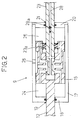
- is a schematic sectional view of the device of FIG. 1 in a rest position;
- FIG. 3
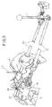
- is a view of a second embodiment of the device of the present invention mounted to a rod-type of gear shift; and
- FIG. 4
- is a schematic section view of the device of FIG. 3 in a rest position.
- With reference to the attached FIGS. 1 and 2, numeral 1 designates the shift lever for remotely controlling an automobile gearbox of the type employing two Bowden
cables gearbox 6, generally fitted in the motor compartment. -
Cable 3 for transmitting gear select motion is normally connected to the corresponding lever 7 ongearbox 6, A servo-actuator 9 is interposed in series oncable 4 for transmitting gear select motion. Servo-actuator 9 is supported by abracket 10 anchored to the housing 11 ofgearbox 6. Arod 12 extending out of servo-actuator 9 connects through anarm 13 to a gearselect lever 14 ofgearbox 6. - Referring particularly to FIG. 2, as shown,
rod 12 is part of servo-actuator 9, which is also composed of adistributor piston 16 inserted within acylinder 17.Cylinder 17 is closed on oneside 18 except for a throughhole 19 lettingrod 12 out, and is provided with acap 20 on the opposite end also having a throughhole 21. - Inserted in through
hole 21 is the end of apiston 23 co-operating with thedistributor 16 to bring either of twochambers Chambers distributor piston 16, the walls ofcylinder 17 andcap 20. The vacuum that always occurs withincylinder 17 when the engine is running, is provided withincylinder 17 by means of a radialcentral bore 26 and aduct 27 communicating with the air inlet manifold (not shown) of the engine. Atmospheric air is introduced in cylinder through anaxial bore 28 controlled by anon-return valve 28a. Bore 28 is obtained inplunger 23 and connected through aduct 29 to a filter (not shown). - Following displacement of
plunger 23 throughcable 4, atmospheric pressure in one of the twochambers distributor piston 16 and ofrod 12 which operateslever 14 througharm 13, thereby shifting the desired gear on or off. Return ofplunger 23 to its neutral position is guaranteed by the biasing force of aspring 23a. - As apparent, the servo-controlled device of the above discussed embodiment may be replaced without inconveniences, for example by a pressurised fluid device.
- FIG. 3 illustrates a gear shift remote control wherein the shift lever 1 and the gear select and shift levers of
gearbox 6 are connected by two rigid rods, a resistingrod 31 and agear select rod 32. According to the invention, mounted to gearselect rod 34 is a servo-actuator 34 driven by adistributor 41 which is mounted in series to resistingrod 31. - Referring to FIG. 4, servo-
actuator 34 consists of acylinder 35 in which there is located aplunger 36 securely attached to arod 37 extending out ofcylinder 37 and defining therein twoseparate chambers rod 37 is connected in known manner to thegear select rod 32, while the other end is connected to the shift lever (not shown). The servo-actuator is driven by adistributor 41 consisting of ahollow cylinder 43 the ends of which are closed bycaps 44. Located withinhollow cylinder 43 are twoplungers rod 47 having one end attached torod 31 and the other end attached to acontrasting lever 49 fitted on thegearbox 6. - The
distributor 41, as known to those skilled in the art, provides twoside chambers central chamber 53. The latter communicates with the air inlet manifold (not shown) of the engine through aradial port 54 and aconduit 55. The twoside chambers conduits chambers actuator 34 through twointermediate chambers plungers conduits cylinders - As apparent, displacement of
plungers rod 31 on shift lever 1 at the moment of gear selection puts one of the twochambers actuator 34 in a vacuum condition following commutation ofdistributor 41. Particularly, translation of theplungers intermediate chambers 60, 61 (and also thecorresponding chamber 39 or 40) communicating with the vacuum existing incentral chamber 53, while closing the port corresponding tochambers - In this way servo-action is accomplished in displacing
rod 32 so as to allow to reduce the effort to be exerted to perform gear selection. Springs 66 provide return ofplungers - Similarly to the first embodiment, another type of servo-actuator means may be used without departing from the scope of the present invention.
Claims (6)
- An automobile gear shift remote control, of the kind employing two Bowden cables (3, 4) or two rods (31, 32) or one rod and one cable, one for transmitting gear select motion and the other for transmitting gear shift motion, from the shift lever (1) to the axles of a gearbox (6) located in the motor compartment,
characterized in that mounted in series to the cable (4) or the lever (32) transmitting gear shift motion is a servo-actuator device (9, 34) for reducing the effort required for gear shifting. - A gear shift remote control according to claim 1, characterized in that the servo-actuator device (9, 34) is a vacuum-operated pneumatic device.
- A gear shift remote control according to claim 1, characterized in that the servo-actuator device (9, 34) is a pressure operated hydraulic device.
- A gear shift remote control according to claim 1, characterized in that the servo-actuator device (9) of the cable (3, 4) control is composed of a closed cylinder (17) wherein a vacuum distributor piston (16) is located, said distributor piston being connected to the shift lever (14) through a control rod (12) extending out of said cylinder (17); and that said distributor piston (16) being driven by a plunger (23) connected to the gear shift cable (4) to translate said piston in response to vacuum within cylinder (17) for actuating gear selection and shifting through said rod (12).
- A gear shift remote control according to claim 1, characterized in that said servo-actuator device (34) of the rod (31, 32) control is composed of a closed cylinder (35) containing a plunger (36) for translating within said cylinder and connected on one side to the gear shift lever through a rod (37) and on the other side to the gear shift rod (32); said plunger being moved by vacuum controlled by a distributor (41) disposed in series on the resisting rod (31) of the gearbox (6).
- A gear shift remote control according to claims 1 and 5, characterized in that said vacuum distributor (41) is adapted for delivering vacuum to said servo-actuator device in response to translating motion of said resisting rod (31).
Applications Claiming Priority (2)
| Application Number | Priority Date | Filing Date | Title |
|---|---|---|---|
| ITTO940573 | 1994-07-15 | ||
| IT94TO000573A IT1266878B1 (en) | 1994-07-15 | 1994-07-15 | SERVO-ASSISTED GEARBOX CONTROL FOR A CAR VEHICLE. |
Publications (1)
| Publication Number | Publication Date |
|---|---|
| EP0692658A1 true EP0692658A1 (en) | 1996-01-17 |
Family
ID=11412665
Family Applications (1)
| Application Number | Title | Priority Date | Filing Date |
|---|---|---|---|
| EP95110990A Withdrawn EP0692658A1 (en) | 1994-07-15 | 1995-07-13 | A gear shift remote servo-control for motor vehicles |
Country Status (2)
| Country | Link |
|---|---|
| EP (1) | EP0692658A1 (en) |
| IT (1) | IT1266878B1 (en) |
Cited By (10)
| Publication number | Priority date | Publication date | Assignee | Title |
|---|---|---|---|---|
| EP0809048A1 (en) * | 1996-05-23 | 1997-11-26 | Renault | Gear shift device for automotive vehicles with shifting assistance to certain ratios |
| WO1998038444A1 (en) * | 1997-02-28 | 1998-09-03 | Ace Engineering S.A. | Booster device for gear box |
| EP0872670A3 (en) * | 1997-04-18 | 1999-02-10 | Keihin Seimitsu Kogyo Co., Ltd. | Power shifter control system |
| WO2000014438A1 (en) * | 1998-09-02 | 2000-03-16 | Zf Friedrichshafen Ag | Shifting device for a variable-speed automobile transmission |
| DE102004054258B3 (en) * | 2004-11-09 | 2006-04-13 | Voith Turbo Gmbh & Co. Kg | Actuating device for controlling the gear change of a motor vehicle transmission |
| WO2007032685A1 (en) * | 2005-09-13 | 2007-03-22 | Kongsberg Automotive As | Cable valve |
| WO2012031612A2 (en) | 2010-09-08 | 2012-03-15 | Kongsberg Automotive As | Servo assisted actuating system for a multispeed gearbox of a vehicle |
| DE19900820B4 (en) * | 1998-01-16 | 2013-03-14 | Schaeffler Technologies AG & Co. KG | Power assistance device for a transmission |
| FR2979858A1 (en) * | 2011-09-09 | 2013-03-15 | Peugeot Citroen Automobiles Sa | Device for sealing passage of control cable of e.g. automatic gearbox between passenger compartment and external zone of car, has guiding unit for allowing adaptation of cable to different positions and/or angles relative to wall surface |
| FR3055385A1 (en) * | 2016-08-26 | 2018-03-02 | Dongfeng Commercial Vehicle Company Limited | A UNIVERSAL OVERSIZED GEARBOX CONTROL DEVICE AND METHOD OF USING THE SAME |
Citations (5)
| Publication number | Priority date | Publication date | Assignee | Title |
|---|---|---|---|---|
| US2245714A (en) * | 1939-02-09 | 1941-06-17 | Bendix Prod Corp | Transmission control mechanism |
| US2303937A (en) * | 1938-12-27 | 1942-12-01 | Harold O Clayton | Transmission control |
| FR2404545A1 (en) * | 1977-09-29 | 1979-04-27 | Teleflex Morse Ltd | REMOTE CONTROL MECHANISM |
| GB2127180A (en) * | 1982-09-16 | 1984-04-04 | Teleflex Morse Ltd | Power assistance device |
| FR2632038A1 (en) * | 1988-05-27 | 1989-12-01 | Renault Vehicules Ind | Gear box control movement transmission device |
-
1994
- 1994-07-15 IT IT94TO000573A patent/IT1266878B1/en active IP Right Grant
-
1995
- 1995-07-13 EP EP95110990A patent/EP0692658A1/en not_active Withdrawn
Patent Citations (5)
| Publication number | Priority date | Publication date | Assignee | Title |
|---|---|---|---|---|
| US2303937A (en) * | 1938-12-27 | 1942-12-01 | Harold O Clayton | Transmission control |
| US2245714A (en) * | 1939-02-09 | 1941-06-17 | Bendix Prod Corp | Transmission control mechanism |
| FR2404545A1 (en) * | 1977-09-29 | 1979-04-27 | Teleflex Morse Ltd | REMOTE CONTROL MECHANISM |
| GB2127180A (en) * | 1982-09-16 | 1984-04-04 | Teleflex Morse Ltd | Power assistance device |
| FR2632038A1 (en) * | 1988-05-27 | 1989-12-01 | Renault Vehicules Ind | Gear box control movement transmission device |
Cited By (15)
| Publication number | Priority date | Publication date | Assignee | Title |
|---|---|---|---|---|
| EP0809048A1 (en) * | 1996-05-23 | 1997-11-26 | Renault | Gear shift device for automotive vehicles with shifting assistance to certain ratios |
| WO1998038444A1 (en) * | 1997-02-28 | 1998-09-03 | Ace Engineering S.A. | Booster device for gear box |
| FR2760263A1 (en) * | 1997-02-28 | 1998-09-04 | Dominique Crasset | ASSISTANCE DEVICE FOR GEARBOX |
| EP0872670A3 (en) * | 1997-04-18 | 1999-02-10 | Keihin Seimitsu Kogyo Co., Ltd. | Power shifter control system |
| US5979258A (en) * | 1997-04-18 | 1999-11-09 | Keihin Seimtsu Kogyo Co., Ltd. | Power shifter control system |
| DE19900820B4 (en) * | 1998-01-16 | 2013-03-14 | Schaeffler Technologies AG & Co. KG | Power assistance device for a transmission |
| WO2000014438A1 (en) * | 1998-09-02 | 2000-03-16 | Zf Friedrichshafen Ag | Shifting device for a variable-speed automobile transmission |
| DE102004054258B3 (en) * | 2004-11-09 | 2006-04-13 | Voith Turbo Gmbh & Co. Kg | Actuating device for controlling the gear change of a motor vehicle transmission |
| CN101258344B (en) * | 2005-09-13 | 2013-02-06 | 孔斯贝格汽车公司 | Cable valve |
| WO2007032685A1 (en) * | 2005-09-13 | 2007-03-22 | Kongsberg Automotive As | Cable valve |
| WO2012031612A2 (en) | 2010-09-08 | 2012-03-15 | Kongsberg Automotive As | Servo assisted actuating system for a multispeed gearbox of a vehicle |
| CN103154536A (en) * | 2010-09-08 | 2013-06-12 | 孔斯贝格汽车公司 | Servo assisted actuating system for a multispeed gearbox of a vehicle |
| CN103154536B (en) * | 2010-09-08 | 2015-05-20 | 孔斯贝格汽车公司 | Servo assisted actuating system for a multispeed gearbox of a vehicle |
| FR2979858A1 (en) * | 2011-09-09 | 2013-03-15 | Peugeot Citroen Automobiles Sa | Device for sealing passage of control cable of e.g. automatic gearbox between passenger compartment and external zone of car, has guiding unit for allowing adaptation of cable to different positions and/or angles relative to wall surface |
| FR3055385A1 (en) * | 2016-08-26 | 2018-03-02 | Dongfeng Commercial Vehicle Company Limited | A UNIVERSAL OVERSIZED GEARBOX CONTROL DEVICE AND METHOD OF USING THE SAME |
Also Published As
| Publication number | Publication date |
|---|---|
| IT1266878B1 (en) | 1997-01-21 |
| ITTO940573A0 (en) | 1994-07-15 |
| ITTO940573A1 (en) | 1996-01-15 |
Similar Documents
| Publication | Publication Date | Title |
|---|---|---|
| US5125326A (en) | Three position actuator having a neutral normal position for shifting a two speed transfer case | |
| JP2746626B2 (en) | Coupling device | |
| EP0803651B1 (en) | Fluid-controlled actuator assembly | |
| GB2024965A (en) | Apparatus for power-assisted gear changing in mechanical gearboxes | |
| US6202812B1 (en) | Simplified transfer case shift actuator | |
| US3766793A (en) | Transmission shift controls | |
| ITTO940573A1 (en) | SERVO-ASSISTED GEARBOX CONTROL FOR A CAR VEHICLE. | |
| GB2052002A (en) | Servo actuator for vehicle clutch | |
| CN101680462A (en) | Power boosting device | |
| US4788821A (en) | Hydraulic shift for motor vehicle transmission | |
| CA1116030A (en) | Multi position fluid actuator | |
| EP0802356B1 (en) | An electro-hydraulic device for controlling a servo-actuated gearbox | |
| US4436191A (en) | Automobile hand control | |
| US4795000A (en) | Cruise control device for automotive vehicles | |
| JPH05296206A (en) | Controller for pressure medium servomotor with axial piston structure | |
| GB2191542A (en) | Vehicle engine throttle valve control in response to wheel slip | |
| CA1271391A (en) | Vehicle hydraulic actuating system | |
| US5517875A (en) | Gear shifting device of a pneumatic transmission | |
| GB2076101A (en) | A device for signalling the clutch wear in servoclutches particularly for motor vehicles | |
| GB2305699A (en) | Actuating device for actuating a selector rod of a motor vehicle gearbox | |
| EP0037197A2 (en) | Splitter control for a transmission | |
| US5142927A (en) | Device for controlling a gear box of a vehicle, particularly an agricultural tractor | |
| JPH01301933A (en) | Controller for controlling operation of fuel control member of engine for vehicle | |
| US4358988A (en) | Control elements for gearbox ratio selectors in heavy vehicles | |
| US5261235A (en) | Hydraulic pressure actuating systems and reservoirs for same |
Legal Events
| Date | Code | Title | Description |
|---|---|---|---|
| PUAI | Public reference made under article 153(3) epc to a published international application that has entered the european phase |
Free format text: ORIGINAL CODE: 0009012 |
|
| AK | Designated contracting states |
Kind code of ref document: A1 Designated state(s): DE ES FR GB SE |
|
| STAA | Information on the status of an ep patent application or granted ep patent |
Free format text: STATUS: THE APPLICATION IS DEEMED TO BE WITHDRAWN |
|
| 18D | Application deemed to be withdrawn |
Effective date: 19960718 |