EP0692425A1 - Method and system for formationkeeping between orbiting spacecraft by varying their ballistic coefficients - Google Patents
Method and system for formationkeeping between orbiting spacecraft by varying their ballistic coefficients Download PDFInfo
- Publication number
- EP0692425A1 EP0692425A1 EP95110366A EP95110366A EP0692425A1 EP 0692425 A1 EP0692425 A1 EP 0692425A1 EP 95110366 A EP95110366 A EP 95110366A EP 95110366 A EP95110366 A EP 95110366A EP 0692425 A1 EP0692425 A1 EP 0692425A1
- Authority
- EP
- European Patent Office
- Prior art keywords
- spacecraft
- surface area
- satellite
- facing
- altering
- Prior art date
- Legal status (The legal status is an assumption and is not a legal conclusion. Google has not performed a legal analysis and makes no representation as to the accuracy of the status listed.)
- Withdrawn
Links
- 238000000034 method Methods 0.000 title claims abstract description 44
- 238000000926 separation method Methods 0.000 claims abstract description 41
- 230000033001 locomotion Effects 0.000 claims abstract description 33
- 238000003780 insertion Methods 0.000 claims description 5
- 230000037431 insertion Effects 0.000 claims description 5
- 230000008859 change Effects 0.000 abstract description 7
- 230000005855 radiation Effects 0.000 description 18
- 230000000694 effects Effects 0.000 description 10
- 230000003247 decreasing effect Effects 0.000 description 8
- 230000007423 decrease Effects 0.000 description 5
- 230000001141 propulsive effect Effects 0.000 description 5
- 230000001133 acceleration Effects 0.000 description 4
- 239000003380 propellant Substances 0.000 description 4
- 230000009471 action Effects 0.000 description 3
- 230000015572 biosynthetic process Effects 0.000 description 3
- 238000009966 trimming Methods 0.000 description 3
- 238000012937 correction Methods 0.000 description 2
- 238000010586 diagram Methods 0.000 description 2
- 238000012423 maintenance Methods 0.000 description 2
- 238000005259 measurement Methods 0.000 description 2
- 230000000737 periodic effect Effects 0.000 description 2
- 230000008569 process Effects 0.000 description 2
- 230000004044 response Effects 0.000 description 2
- 230000009291 secondary effect Effects 0.000 description 2
- 230000002411 adverse Effects 0.000 description 1
- 230000005540 biological transmission Effects 0.000 description 1
- 238000004891 communication Methods 0.000 description 1
- 238000010276 construction Methods 0.000 description 1
- 230000005484 gravity Effects 0.000 description 1
- 230000007774 longterm Effects 0.000 description 1
- 230000007246 mechanism Effects 0.000 description 1
- 238000012544 monitoring process Methods 0.000 description 1
- 230000008685 targeting Effects 0.000 description 1
Images


Classifications
-
- B—PERFORMING OPERATIONS; TRANSPORTING
- B64—AIRCRAFT; AVIATION; COSMONAUTICS
- B64G—COSMONAUTICS; VEHICLES OR EQUIPMENT THEREFOR
- B64G1/00—Cosmonautic vehicles
- B64G1/22—Parts of, or equipment specially adapted for fitting in or to, cosmonautic vehicles
- B64G1/40—Arrangements or adaptations of propulsion systems
- B64G1/407—Solar sailing
-
- B—PERFORMING OPERATIONS; TRANSPORTING
- B64—AIRCRAFT; AVIATION; COSMONAUTICS
- B64G—COSMONAUTICS; VEHICLES OR EQUIPMENT THEREFOR
- B64G1/00—Cosmonautic vehicles
- B64G1/10—Artificial satellites; Systems of such satellites; Interplanetary vehicles
- B64G1/1085—Swarms and constellations
-
- B—PERFORMING OPERATIONS; TRANSPORTING
- B64—AIRCRAFT; AVIATION; COSMONAUTICS
- B64G—COSMONAUTICS; VEHICLES OR EQUIPMENT THEREFOR
- B64G1/00—Cosmonautic vehicles
- B64G1/22—Parts of, or equipment specially adapted for fitting in or to, cosmonautic vehicles
- B64G1/24—Guiding or controlling apparatus, e.g. for attitude control
- B64G1/242—Orbits and trajectories
-
- B—PERFORMING OPERATIONS; TRANSPORTING
- B64—AIRCRAFT; AVIATION; COSMONAUTICS
- B64G—COSMONAUTICS; VEHICLES OR EQUIPMENT THEREFOR
- B64G1/00—Cosmonautic vehicles
- B64G1/10—Artificial satellites; Systems of such satellites; Interplanetary vehicles
- B64G1/1007—Communications satellites
-
- B—PERFORMING OPERATIONS; TRANSPORTING
- B64—AIRCRAFT; AVIATION; COSMONAUTICS
- B64G—COSMONAUTICS; VEHICLES OR EQUIPMENT THEREFOR
- B64G1/00—Cosmonautic vehicles
- B64G1/22—Parts of, or equipment specially adapted for fitting in or to, cosmonautic vehicles
- B64G1/222—Parts of, or equipment specially adapted for fitting in or to, cosmonautic vehicles for deploying structures between a stowed and deployed state
-
- B—PERFORMING OPERATIONS; TRANSPORTING
- B64—AIRCRAFT; AVIATION; COSMONAUTICS
- B64G—COSMONAUTICS; VEHICLES OR EQUIPMENT THEREFOR
- B64G1/00—Cosmonautic vehicles
- B64G1/22—Parts of, or equipment specially adapted for fitting in or to, cosmonautic vehicles
- B64G1/24—Guiding or controlling apparatus, e.g. for attitude control
- B64G1/244—Spacecraft control systems
Definitions
- This invention relates to orbiting spacecraft and more particularly to a system and method for formationkeeping between two or more orbiting spacecraft by modulating their respective ballistic coefficients during at least a portion of their respective orbits while they are at sufficiently low altitude to experience atmospheric drag.
- Satellites in low altitude orbits are useful for a variety of applications. Many such applications require the use of a network, or constellation, of two or more cooperating satellites in a co-planar orbit.
- constellation a network of sixteen or more satellites in low Earth orbit, has been deployed for use as an ultra-precise radio location system for determining the distance between two locations separated by large distances on the surface of the Earth to an accuracy of a few centimeters.
- constellations of satellites in low Earth orbits can be used to implement systems for communication between two points on the surface of the Earth.
- the perturbative forces on an orbiting spacecraft vary due to a number of factors, including the oblateness of the Earth (which results in gravitational forces not being uniform throughout the orbit), variations in atmospheric density and temperature (which affect drag) and the magnitude of solar activity (which results in fluxuations in solar pressure). Because the forces due to these factors are not uniform over an entire orbit and because the mass and profile of each satellite can vary over time and from one satellite to another, atmospheric drag and the other perturbations affect the inter-satellite spacing of orbiting constellations over time. Fortunately, techniques known in the art can be used to predict the magnitude and variation of these perturbative forces so that orbital maintenance can be performed.
- each satellite in the constellation must compensate for the perturbative forces it experiences.
- the compensating maneuvers performed by the satellites in the formation are known in the art as “formationkeeping” or “formationflying.”
- formationkeeping When only a single satellite is involved, compensating maneuvers to maintain constant satellite-to-station distances are called “stationkeeping.”
- the studies do not provide a fully generalized technique for maintaining a formation of two or more satellites orbiting as a constellation.
- control of differential drag between two satellites was used to maintain a relative distance between a slave satellite and a master (i.e., a reference) satellite involving relatively short line-of-sight distances.
- Matthews and Leszkiewicz describe a technique for maintaining the distance between orbiting platforms and a reference satellite (i.e., the Space Station).
- the principal object of this invention is to provide an improved system and method for formationkeeping in a constellation of orbiting satellites. More specifically, it is an object of this invention to provide a system and method for maintaining the desired spacing (whether fixed or periodic) of a constellation of two or more satellites by using satellite orientation or the orientation of a portion thereof as a means for altering the surface area of the satellite and thereby altering the atmospheric drag force and/or the solar radiation pressure exerted on that satellite.
- the formationkeeping system and method includes one or more networks of co-planar constellations of spaced orbiting satellites, wherein each satellite in the network can alter its surface area facing the direction of perturbative forces acting on the satellite.
- a control system (which may be ground based or located on-board the satellite) is provided which measures the position and velocity of each satellite, computes the position and velocity differences between the satellites and compares these differences to a position and velocity threshold level. If the actual position and velocity differences exceed acceptable tolerances, the control system corrects for the positional error by altering the windward surface area of the satellite and hence its ballistic coefficient. As a result, relative satellite position and velocity are controlled by the change in magnitude of the atmospheric drag forces exerted on the satellite.
- control system can alter the surface area in the direction of solar radiation pressure to control the position and velocity of the satellites by the change in magnitude of the solar forces exerted on the satellite.
- control by variation of drag force and solar radiation pressure could be used.
- the atmospheric drag or solar radiation surface area of each satellite in the constellation can be modified by altering either the solar panel position or the yaw axis of the satellite or both.
- the solar panel on each satellite can be rotated about an axis perpendicular to the direction of satellite motion thereby varying the windward surface area of the satellite.
- solar panel adjustments can be made while the satellite is in the eclipse portion of its orbit without adverse effects on the satellite's power supply.
- the yaw angle (as well as the pitch or roll, depending upon the application) of each satellite can be varied, which also has the effect of changing the surface area of the satellite in the direction of motion.
- the methods of the present invention can be used for any constellation of satellites, preferably in co-planar orbit, at any inclination or altitude where atmospheric drag and/or solar radiation pressure is a significant cause of relative motion between the satellites.
- the method of the present invention can be used in conjunction with either a ground-based or an autonomous formationkeeping system. These methods can also be used for stationkeeping a single satellite in a desired position relative to an orbiting space station.
- the method and system of the present invention has a number of advantages over prior systems.
- the method of controlling satellite motion by modulating atmospheric drag or solar radiation forces exerted on the individual satellites produces relatively small corrective forces, thus preventing the creation of secondary errors which were common in the propulsive formationkeeping techniques used in prior systems.
- a method and system for achieving an initial orbit of one or more satellites or for establishing the initial formation of a network of deployed satellites.
- the system alters satellite surface area in the direction of motion (i.e., the ballistic coefficient) to increase or decrease drag forces exerted on the satellite in order to achieve the precise velocity profiles required by initial orbit maneuvers.
- the control system alters the spacecraft surface area in the direction of the solar radiation pressure to increase or decrease solar forces exerted on the satellite in order to control the velocity profile of the satellite.
- both drag and solar pressure are varied by modulating the respective surface areas of the satellite to control the velocity profile of the spacecraft.
- the planar separation between many coplanar constellations of satellites can be maintained by using ballistic coefficient control.
- the ballistic coefficients of all the satellites in a constellation orbiting in the same plane are adjusted relative to those orbiting in an adjacent plane.
- the rate of precession of one orbit is altered relative to the adjacent orbit so that the angular spacing between the orbits can be controlled.
- FIG. 1 shows a co-planar and co-orbital network or constellation 10 of satellites 12 in low altitude orbit around the Earth 14.
- Each satellite 12 or a portion thereof is capable of independent changes in orientation with respect to orbital motion.
- accurate spacing between satellites in low Earth orbit is critical for many applications.
- the present invention includes a control means for monitoring the spacing between satellites 12 and maintaining the inter-satellite distances within a desired tolerance. To correct for any positional errors found, the control system signals the affected satellites to change their orientation by altering the amount of surface area facing the direction of satellite motion or the direction of solar pressure as described more fully below.
- the system of this invention modulates the drag and solar forces F exerted on satellites 12 in response to the inter-satellite positional error and thereby controls the inter-satellite spacing.
- the surface area adjustments are made by changing the orientation of the solar panels 20 of the satellite or by changing the orientation of the satellite itself or both.
- the orientation of solar panels 20 on the satellite to affect its ballistic coefficient can be carried out during the portion of the orbit where the sun is in eclipse so as to not affect the solar energy available to the satellite.
- the invention is illustrated for use with satellite constellations in low Earth orbit, the invention is also suitable for use with constellations in any orbit where perturbations due to atmospheric drag and/or solar radiation pressure are significant.
- the methods of the present invention can be used to maintain constant satellite-to-station distances, where the station is in orbit along with the satellite, as well as inter-satellite distances as shown in the illustrated embodiment.
- Orbiting satellites can be subjected to significant perturbative forces F due to atmospheric drag or solar radiation pressure.
- drag force F is tangential to the satellite orbit and opposite in direction to constellation motion V.
- F S is the solar constant (1358 W/M)
- C is the speed of light (3 X 10⁸ M/S)
- a S is the surface area of the satellite 12 facing in the direction of the solar force
- q is the reflectance factor
- i is the angle of incidence to the sun
- M is the satellite mass.
- changes in the ballistic coefficient of each satellite 12 in constellation 10 are produced by varying the surface area A of each satellite that faces the direction of motion.
- equations (1) through (3) by changing the orientation of satellite 12 (or a portion thereof) such that its area A is increased, the satellite's ballistic coefficient B is decreased, thus increasing the drag force on the satellite.
- the drag surface area A is decreased, the ballistic coefficient of the satellite is increased and hence the atmospheric drag force F decreases.
- equation (4) by varying the amount of surface area A S facing the direction of force due to solar pressure, the acceleration of the satellite due to these forces can be increased or decreased.
- the satellite surface area adjustments produce corrective forces that modify the in-track spacing of the satellites. Unlike prior propellant-based systems, these corrective forces are, on average, comparable in size to perturbative forces and, therefore, are less likely to cause undesirable secondary effects.
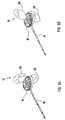
- FIG. 2 illustrates the methods by which the cross-sectional area of satellite 12 is manipulated in conformance with the present invention.
- Satellite 12 includes a body or disk 18, a nadir-pointing antenna system 16 and a pair of solar panels 20 and 22 extending perpendicularly from the disk 18 for providing power to the satellite.
- Solar panels 20 and 22 are mounted on hinges (not shown) so that the panels can be folded for convenient stowage.
- solar panels 20 and 22 are mounted for rotation about an axis 24 in the direction shown in FIG. 2 by arrow 26. The rotation of solar panels 20 and 22 about axis 24 can be used, for example, to vary the surface area of satellite 12 in the plane perpendicular to the direction of motion and for maximizing the amount of solar radiation absorbed by panels 20 and 22.
- Satellite 12 is constructed for movement about a yaw axis 28 in the direction of motion shown by arrow 30 in FIG. 2.
- the yaw movement of satellite 12 about axis 28 is substantially perpendicular to the rotational movement of solar panels 20 and 22 about axis 24, thereby providing a second axis of movement. Additionally, this second axis of movement provides a second means for increasing or decreasing the surface area of satellite 12 in the direction of motion or in the direction of solar pressure.
- the yaw movement of satellite 12 is achieved by a conventional attitude control system.
- the details of the general construction of satellite 12 is disclosed in a copending application, assigned to the assignee of the present invention, for a "Satellite Having a Stackable Configuration", Serial No. 08/191831 filed on February 4, 1994, the disclosure of which is hereby incorporated by reference into the present application.
- the surface area of satellite 12 can be varied by rotating solar panels 20 and 22 about axis 24.
- disk 18 of satellite 12 lies in the plane of the orbit of constellation 10 (i.e., at a yaw angle of 0°)
- rotating solar panels 20 and 22 toward 90° about axis 24 increases the satellite surface area thereby increasing the atmospheric drag forces F.
- FIG. 3b An illustration of satellite 12 with its solar panels 20 and 22 in the flared position is shown in FIG. 3b.
- satellite surface area, and hence atmospheric drag F can be minimized by "feathering" solar panels 20 and 22 substantially as shown in FIG. 3a.
- the surface area of satellite 12 can also be varied by rotation about yaw axis 28. As best illustrated in FIG. 2, when satellite 12 rotates about axis 28, the surface area A due to the profile of satellite disk 18 gradually increases, reaching a maximum when the yaw angle is 90°. It should be noted that in the preferred embodiment, radiation patterns emitted by antenna system 16 are substantially symmetrical about axis 28 so that yaw rotation to alter the satellite cross-sectional surface area does not affect radio transmissions. It should also be observed that the influence of solar panels 20 and 22 on drag force F diminishes as the yaw angle of satellite 12 increases.
- solar panels 20 and 22 as a means of controlling drag and solar pressure forces is somewhat constrained by the power requirements of satellite 12. While satellite 12 is exposed to the sun, it is desirable that the orientation of the satellite and the solar panels 20 and 22 be maintained to maximize the amount of solar radiation incident to the solar panels. However, the orientation of satellite 12 and solar panels 20 and 22 is virtually unconstrained for most of the period that the satellite is not exposed to the sun (i.e., when the satellite 12 is in the eclipse portion of its orbit). During this time, modulation of atmospheric drag forces can be accomplished at least partially through variation of the position of solar panels 20 and 22, the orientation of disk 18, or a combination of these.
- FIG. 5 is a schematic block diagram of the formationkeeping control system of the present invention. It is to be noted that although the control system will be described as using variations in atmospheric drag surface area (and hence in the ballistic coefficient of the satellite) to change satellite position and velocity, the control system can also use variations in surface area in the direction of solar radiation pressure to alter satellite motion where the magnitude of the solar pressure is significant.
- the control system receives the actual position of each satellite 12 in constellation 10.
- each satellite 12 is equipped with a position and velocity measuring device.
- a NAVSTARTM Global Positioning System (GPS) receiver can be used for this purpose.
- the GPS comprises a constellation of reference satellites that emit a reference signal.
- the GPS receivers 40 on board satellite 12 calculate accurate absolute position and velocity information from the reference signal. This information is then transmitted via telemetry subsystems 42 and 44 to the ground-based control system 60 on the Earth's surface.
- the operation of the control system 60 is described with reference to a ground-based system, the methods of the present invention could also be used with satellite-to-satellite crosslinks to allow for autonomous control.
- the control system 60 computes the differences in position and velocity of each satellite 12 in constellation 10.
- the current position differences i.e., phase angle as shown in block 48
- velocity i.e., phase angle rate
- the control system 60 initiates corrective action by computing new position commands at block 50 and transmitting the commands to the affected satellites through command subsystem 52 and the telemetry subsystem 42 of the spacecraft. These commands are passed to the spacecraft's attitude control system 54, which makes the required adjustments.
- the control system When the separation between any two satellites exceeds acceptable limits, at block 50 the control system generates commands so that the satellites with the greatest velocity will decrease their surface area by feathering their solar panels (hence, increasing their ballistic coefficient). The remaining (i.e., slower) satellites will increase their surface area by flaring their solar panels (hence, decreasing their ballistic coefficient). Consequently, energy is removed from the orbit of the slower satellites which causes the orbit to decay slightly. These satellites will then have a shorter orbit period and, therefore, the mean velocity of the satellites increases. Conversely, decreasing the surface area of the faster satellites decreases the rate of orbit decay and, therefore, the velocity of these satellites tends to remain constant. The process continues until all satellites attain the desired spacing and same mean velocity.
- Control system 60 also employs a predictive algorithm to compensate for the large lag times inherent in the control of satellite motion through changes in its ballistic coefficient.
- the predictor uses a model of the space environment along with measurements of actual satellite motion to initiate control before the separation between the satellites reaches its critical threshold value.
- the velocity measurements of all the satellites in the constellation are used to compute the rates of separation between all the satellites and, based on these separation rates, to estimate when the respective satellites will reach the separation threshold.
- the control system estimates the duration of the ballistic coefficient control process (i.e., "the control duration window") based on current orbit parameters and the expected magnitude of the perturbative forces.
- the control system initiates a change in the satellite surface area (if necessary) before the satellites reach the separation threshold.
- the controlled satellites are commanded to change their position so as to maximize or minimize, their ballistic coefficients (and hence to minimize or maximize, respectively, the drag force F that each satellite experiences).
- the control system can employ other algorithms that vary the ballistic coefficient as a function of the positional error magnitude, e.g., proportional or integral control or a combination thereof.
- the ballistic coefficient can be increased or decreased by feathering or flaring solar panels 20 and 22, respectively, about axis 24 or by increasing or decreasing the yaw angle of satellite 12, respectively, about axis 28 or by a combination of both maneuvers.
- FIG. 4 shows the control band of a two-satellite constellation using an on/off control method.
- the satellite position oscillates about the optimum by a small amount due to periodic gravitational effects on the orbits of the two satellites.
- the control system is stable because the variation in atmospheric drag force produced by the control maneuvers is relatively small.
- Modulation of satellite ballistic coefficients in accordance with this invention produces a 15% variation in long-term average drag force F on each satellite. This is only several times larger than the perturbations which cause the satellite to drift apart. As a result, minimal secondary errors are introduced by the control system.
- Propulsive formationkeeping systems produce forces on the order of hundreds of times these orbit perturbations, which can cause undesirable secondary effects.
- the present invention also provides a method for "formationfinding," or final orbit trimming, to initiate the orbit of a deployed satellite.
- the satellite 12 In targeting to achieve a particular orbit, the satellite 12 must undergo several precise maneuvers to eliminate the effect of the forces imposed on the satellite during separation from the launch vehicle. The satellites are detached from the launch vehicle so that their initial velocities cause the satellites to separate and move towards their final spacing. Next, initial orbit maneuvers are performed to synchronize the orbits. Where, as in prior systems, the maneuvers are performed by thrusters, orbit insertion can be incomplete because even the smallest available thrusters cannot provide energy in precise amounts. In addition, uncertainties regarding satellite position and velocity contribute to orbit insertion errors. As a result, after the insertion maneuvers are completed, the satellites may still drift apart at some small rate.
- FIG. 4 illustrates the initial separation profile of a two-satellite constellation. After separation from the launch vehicle, several thruster maneuvers are used to achieve an initial separation rate as represented by the initial slope in phase angle shown in FIG. 4. The separation rate is then reduced to achieve final orbit trimming by altering the satellite's atmospheric drag surface area or solar radiation surface area or both.
- ballistic coefficient control was employed during eclipse periods for approximately 110 days after the last thruster maneuver.
- control of atmospheric drag and solar radiation forces can be used to maintain planar separations between several adjacent constellations.
- the atmospheric drag or solar radiation pressure surface areas of each satellite in the constellation are varied through solar panel rotation or satellite yaw angle adjustments or both.
- the constellations can achieve proper right ascension separations between themselves.
- the semi-major axes of two constellations can be controlled relative to each other. Because the rate of precession of an orbit depends in part upon its semi-major axis, surface area control of all of the satellites in one orbit plane can vary the angular spacing between that orbit and an adjacent orbit plane.
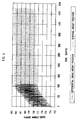
- FIG. 6 is a graph which plots the planar separation between two adjacent orbits of satellites that are being controlled in conformance with the present invention. As shown in FIG. 6 through control of the atmospheric drag forces exerted on the individual satellites in adjacent orbits, planar separation drift (represented by the dashed line trace of FIG. 6) can be eliminated so that the adjacent orbits are maintained at a constant separation (represented by the solid line trace of FIG. 6).
Abstract
The present invention provides a method and system for formationkeeping between two or more orbiting spacecraft (12) by controlling the surface area of the spacecraft facing the direction of perturbative forces acting on the spacecraft. The actual position of each spacecraft (12) is sensed and the distance between the spacecraft is computed. If this separating distance exceeds acceptable tolerances, the affected spacecraft are commanded to change their orientation so that the total surface area facing the direction of motion is altered. Alternatively, the total surface area of the spacecraft facing the direction of solar pressure can be altered. As a result, the forces acting on the spacecraft are altered which alters spacecraft position and velocity. In accordance with another aspect of the invention, surface area variations of individual spacecraft are used to maintain the planar separation between adjacent constellations (10) of orbiting spacecraft at desired distances.
Description
- This invention relates to orbiting spacecraft and more particularly to a system and method for formationkeeping between two or more orbiting spacecraft by modulating their respective ballistic coefficients during at least a portion of their respective orbits while they are at sufficiently low altitude to experience atmospheric drag.
- Satellites in low altitude orbits are useful for a variety of applications. Many such applications require the use of a network, or constellation, of two or more cooperating satellites in a co-planar orbit. For example, "geobeacon", a network of sixteen or more satellites in low Earth orbit, has been deployed for use as an ultra-precise radio location system for determining the distance between two locations separated by large distances on the surface of the Earth to an accuracy of a few centimeters. In addition, constellations of satellites in low Earth orbits can be used to implement systems for communication between two points on the surface of the Earth.
- The use of satellites for such applications often requires that the distance between each satellite in the constellation be maintained within a fairly tight tolerance. Unfortunately, orbiting satellites are subject to "perturbative" forces such as those caused by the non-uniform gravity of the Earth, gravitational effects of other bodies, solar pressure and atmospheric drag. For satellites in low altitude orbits, or orbits having a low altitude perigee about the Earth (low Earth orbit) or any other body having a surrounding atmosphere, atmospheric drag is usually the predominant perturbative force. The perturbative forces on an orbiting spacecraft vary due to a number of factors, including the oblateness of the Earth (which results in gravitational forces not being uniform throughout the orbit), variations in atmospheric density and temperature (which affect drag) and the magnitude of solar activity (which results in fluxuations in solar pressure). Because the forces due to these factors are not uniform over an entire orbit and because the mass and profile of each satellite can vary over time and from one satellite to another, atmospheric drag and the other perturbations affect the inter-satellite spacing of orbiting constellations over time. Fortunately, techniques known in the art can be used to predict the magnitude and variation of these perturbative forces so that orbital maintenance can be performed.
- In order to maintain proper inter-satellite spacing, each satellite in the constellation must compensate for the perturbative forces it experiences. The compensating maneuvers performed by the satellites in the formation are known in the art as "formationkeeping" or "formationflying." When only a single satellite is involved, compensating maneuvers to maintain constant satellite-to-station distances are called "stationkeeping."
- In prior orbital maintenance systems, propulsive corrections have been used to compensate for these orbital perturbative forces. Such techniques have also been used to maintain in-track spacing in formationkeeping or stationkeeping applications. For example, U.S. Patent No. 5,267,167 discloses a method and system that uses propellant fueled thrusters for keeping a constellation of satellites within a predetermined set of time and location goals. Using propulsion to counter perturbative forces, however, has a number of significant drawbacks. First, propulsion requires the expenditure of propellants, which limits the life of the spacecraft and requires additional launch mass. Second, for relatively small spacecraft, the action of even the smallest available propulsion system produces forces that are quite large relative to most perturbative forces, particularly atmospheric drag. This introduces secondary errors for which further corrective action must be taken.
- Some studies have proposed that variations in the atmospheric drag force itself be used to perform formationkeeping or stationkeeping of orbiting spacecraft. These studies have examined the effect of controlling the ballistic coefficient of the spacecraft on spacecraft position and velocity. For example, Matthews and Leszkiewicz derived a series of control equations for maintaining the position of a generalized spacecraft with respect to a reference satellite, such as the Space Station, using the ballistic coefficient of the satellite as the manipulated variable. See Michael Matthews & Susan J. Leszkiewicz, "Efficient Spacecraft Formationkeeping With Consideration of Ballistic Coefficient Control, "AIAA 26th Aero space Sciences Meeting, AA-88-0375, January 1988. In addition, a study by Leonard examines the use of differential drag as an actuator for formationkeeping between two satellites to maintain the position of the "slave" satellite relative to the "master" satellite. See Carolina Lee Leonard, "Formationkeeping of Spacecraft via Differential Drag," M.S. Thesis, Massachusetts Institute of Technology, July 1986. In this study, differential drag between the master and slave satellites is created by varying the angle of attack of drag plates that are attached to each satellite.
- Although these studies describe a useful technique, they fail to solve a number of important practical problems. First, the studies do not provide a fully generalized technique for maintaining a formation of two or more satellites orbiting as a constellation. For example, in the Leonard study, control of differential drag between two satellites was used to maintain a relative distance between a slave satellite and a master (i.e., a reference) satellite involving relatively short line-of-sight distances. Matthews and Leszkiewicz describe a technique for maintaining the distance between orbiting platforms and a reference satellite (i.e., the Space Station).
- Second, the studies do not describe a convenient mechanism for modifying the satellite's ballistic coefficient. In Leonard, differential drag forces between the satellites were controlled by reorienting drag plates attached to the satellites. This solution adds launch mass to the satellite. Although Matthews and Leszkiewicz mention the possibility of varying the ballistic coefficients of spacecraft by adjustments in solar array orientation, they do not provide a method for continuously altering solar panel orientation to control spacecraft position while continuing to satisfying the power requirements of the spacecraft.
- Therefore, there is a need for a method and system for maintaining the desired in-track spacing of two or more independent orbiting satellites by actively controlling the ballistic coefficient of each satellite in the constellation. In addition, there is a need for a method of formationkeeping by adjustment of satellite ballistic coefficient whereby the surface area of each satellite is modified by reorientation of the satellite itself or by reorientation of equipment normally deployed on such satellites.
- The principal object of this invention is to provide an improved system and method for formationkeeping in a constellation of orbiting satellites. More specifically, it is an object of this invention to provide a system and method for maintaining the desired spacing (whether fixed or periodic) of a constellation of two or more satellites by using satellite orientation or the orientation of a portion thereof as a means for altering the surface area of the satellite and thereby altering the atmospheric drag force and/or the solar radiation pressure exerted on that satellite.
- In accordance with the present invention, the formationkeeping system and method includes one or more networks of co-planar constellations of spaced orbiting satellites, wherein each satellite in the network can alter its surface area facing the direction of perturbative forces acting on the satellite. A control system (which may be ground based or located on-board the satellite) is provided which measures the position and velocity of each satellite, computes the position and velocity differences between the satellites and compares these differences to a position and velocity threshold level. If the actual position and velocity differences exceed acceptable tolerances, the control system corrects for the positional error by altering the windward surface area of the satellite and hence its ballistic coefficient. As a result, relative satellite position and velocity are controlled by the change in magnitude of the atmospheric drag forces exerted on the satellite. Alternatively, the control system can alter the surface area in the direction of solar radiation pressure to control the position and velocity of the satellites by the change in magnitude of the solar forces exerted on the satellite. In addition, a combination of control by variation of drag force and solar radiation pressure could be used.
- In accordance with the invention, the atmospheric drag or solar radiation surface area of each satellite in the constellation can be modified by altering either the solar panel position or the yaw axis of the satellite or both. First, the solar panel on each satellite can be rotated about an axis perpendicular to the direction of satellite motion thereby varying the windward surface area of the satellite. Significantly, solar panel adjustments can be made while the satellite is in the eclipse portion of its orbit without adverse effects on the satellite's power supply. Second, the yaw angle (as well as the pitch or roll, depending upon the application) of each satellite can be varied, which also has the effect of changing the surface area of the satellite in the direction of motion.
- The methods of the present invention can be used for any constellation of satellites, preferably in co-planar orbit, at any inclination or altitude where atmospheric drag and/or solar radiation pressure is a significant cause of relative motion between the satellites. In addition, the method of the present invention can be used in conjunction with either a ground-based or an autonomous formationkeeping system. These methods can also be used for stationkeeping a single satellite in a desired position relative to an orbiting space station.
- The method and system of the present invention has a number of advantages over prior systems. First, the system does not require the use of propellants or propulsive thrusters, thus saving on space and mass. Second, the method of controlling satellite motion by modulating atmospheric drag or solar radiation forces exerted on the individual satellites produces relatively small corrective forces, thus preventing the creation of secondary errors which were common in the propulsive formationkeeping techniques used in prior systems. Third, the methods described herein control satellite motion without adding launch mass to the satellite and without affecting the solar energy available to the satellite.
- In accordance with another aspect of the invention, a method and system is provided for achieving an initial orbit of one or more satellites or for establishing the initial formation of a network of deployed satellites. In this mode, the system alters satellite surface area in the direction of motion (i.e., the ballistic coefficient) to increase or decrease drag forces exerted on the satellite in order to achieve the precise velocity profiles required by initial orbit maneuvers. Alternatively, the control system alters the spacecraft surface area in the direction of the solar radiation pressure to increase or decrease solar forces exerted on the satellite in order to control the velocity profile of the satellite. In yet another alternative embodiment, both drag and solar pressure are varied by modulating the respective surface areas of the satellite to control the velocity profile of the spacecraft. The foregoing method allows for more precise control of satellite kinetic energy than was possible in prior propulsive formationkeeping or stationkeeping systems.
- In yet another aspect of the invention, the planar separation between many coplanar constellations of satellites can be maintained by using ballistic coefficient control. In accordance with the invention, the ballistic coefficients of all the satellites in a constellation orbiting in the same plane are adjusted relative to those orbiting in an adjacent plane. As a result, the rate of precession of one orbit is altered relative to the adjacent orbit so that the angular spacing between the orbits can be controlled.
- Other objects and features of the invention will be apparent from the following description and from the drawings.
-
- FIG. 1 is a schematic representation of a constellation of orbiting satellites in conjunction with the present invention;
- FIG. 2 is a detailed perspective view of a satellite according to the invention;
- FIG. 3a is a perspective view of a deployed satellite showing its solar panels in their low drag, or feathered, position;
- FIG. 3b is a perspective view of a deployed satellite showing its solar panels show in their high drag, or flared, position;
- FIG. 4 is a graph showing the control response of a two-satellite constellation being controlled by the methods of the present invention;
- FIG. 5 is a schematic block diagram of the formationkeeping ballistic coefficient control system; and
- FIG. 6 is a graph showing the planar separation between two adjacent orbit planes being controlled by the methods of the present invention.
- FIG. 1 shows a co-planar and co-orbital network or
constellation 10 ofsatellites 12 in low altitude orbit around theEarth 14. Eachsatellite 12 or a portion thereof is capable of independent changes in orientation with respect to orbital motion. As noted above, accurate spacing between satellites in low Earth orbit is critical for many applications. Accordingly, the present invention includes a control means for monitoring the spacing betweensatellites 12 and maintaining the inter-satellite distances within a desired tolerance. To correct for any positional errors found, the control system signals the affected satellites to change their orientation by altering the amount of surface area facing the direction of satellite motion or the direction of solar pressure as described more fully below. As a result, the system of this invention modulates the drag and solar forces F exerted onsatellites 12 in response to the inter-satellite positional error and thereby controls the inter-satellite spacing. The surface area adjustments are made by changing the orientation of thesolar panels 20 of the satellite or by changing the orientation of the satellite itself or both. Advantageously, the orientation ofsolar panels 20 on the satellite to affect its ballistic coefficient can be carried out during the portion of the orbit where the sun is in eclipse so as to not affect the solar energy available to the satellite. - Although the invention is illustrated for use with satellite constellations in low Earth orbit, the invention is also suitable for use with constellations in any orbit where perturbations due to atmospheric drag and/or solar radiation pressure are significant. In addition, the methods of the present invention can be used to maintain constant satellite-to-station distances, where the station is in orbit along with the satellite, as well as inter-satellite distances as shown in the illustrated embodiment.
- Orbiting satellites can be subjected to significant perturbative forces F due to atmospheric drag or solar radiation pressure. As shown in FIG. 1, drag force F is tangential to the satellite orbit and opposite in direction to constellation motion V. The acceleration (a) of
satellite 12 due to drag force F is approximated by the following equation:
Where ρ is the atmospheric density; A is the surface area ofsatellite 12 in the direction of satellite motion; V is the velocity ofsatellite 12; CD is the drag coefficient of the satellite; and M is the satellite mass. The ratio of the satellite mass to the product of its surface area and drag coefficient is known as the ballistic coefficient (B), i.e.,
Substituting this expression into the above expression for acceleration (a) due to drag force F yields:
- Similarly, the acceleration of
satellite 12 due to forces exerted by solar radiation pressure is given by the following expression:
Where FS is the solar constant (1358 W/M); C is the speed of light (3 X 10⁸ M/S); AS is the surface area of thesatellite 12 facing in the direction of the solar force; q is the reflectance factor; i is the angle of incidence to the sun; and M is the satellite mass. - In accordance with the present invention changes in the ballistic coefficient of each
satellite 12 inconstellation 10 are produced by varying the surface area A of each satellite that faces the direction of motion. According to equations (1) through (3), by changing the orientation of satellite 12 (or a portion thereof) such that its area A is increased, the satellite's ballistic coefficient B is decreased, thus increasing the drag force on the satellite. Conversely, if the drag surface area A is decreased, the ballistic coefficient of the satellite is increased and hence the atmospheric drag force F decreases. Similarly, according to equation (4), by varying the amount of surface area AS facing the direction of force due to solar pressure, the acceleration of the satellite due to these forces can be increased or decreased. In effect, the satellite surface area adjustments produce corrective forces that modify the in-track spacing of the satellites. Unlike prior propellant-based systems, these corrective forces are, on average, comparable in size to perturbative forces and, therefore, are less likely to cause undesirable secondary effects. - FIG. 2 illustrates the methods by which the cross-sectional area of
satellite 12 is manipulated in conformance with the present invention.Satellite 12 includes a body ordisk 18, a nadir-pointingantenna system 16 and a pair ofsolar panels disk 18 for providing power to the satellite.Solar panels solar panels axis 24 in the direction shown in FIG. 2 byarrow 26. The rotation ofsolar panels axis 24 can be used, for example, to vary the surface area ofsatellite 12 in the plane perpendicular to the direction of motion and for maximizing the amount of solar radiation absorbed bypanels -
Satellite 12 is constructed for movement about ayaw axis 28 in the direction of motion shown byarrow 30 in FIG. 2. The yaw movement ofsatellite 12 aboutaxis 28 is substantially perpendicular to the rotational movement ofsolar panels axis 24, thereby providing a second axis of movement. Additionally, this second axis of movement provides a second means for increasing or decreasing the surface area ofsatellite 12 in the direction of motion or in the direction of solar pressure. The yaw movement ofsatellite 12 is achieved by a conventional attitude control system. The details of the general construction ofsatellite 12 is disclosed in a copending application, assigned to the assignee of the present invention, for a "Satellite Having a Stackable Configuration", Serial No. 08/191831 filed on February 4, 1994, the disclosure of which is hereby incorporated by reference into the present application. - As noted above, the surface area of
satellite 12 can be varied by rotatingsolar panels axis 24. Wheredisk 18 ofsatellite 12 lies in the plane of the orbit of constellation 10 (i.e., at a yaw angle of 0°), rotatingsolar panels satellite 12 with itssolar panels solar panels solar panels satellite 12 as described more fully below. - The surface area of
satellite 12 can also be varied by rotation aboutyaw axis 28. As best illustrated in FIG. 2, whensatellite 12 rotates aboutaxis 28, the surface area A due to the profile ofsatellite disk 18 gradually increases, reaching a maximum when the yaw angle is 90°. It should be noted that in the preferred embodiment, radiation patterns emitted byantenna system 16 are substantially symmetrical aboutaxis 28 so that yaw rotation to alter the satellite cross-sectional surface area does not affect radio transmissions. It should also be observed that the influence ofsolar panels satellite 12 increases. When thesatellite 12 reaches a yaw angle of 90°,solar panels axis 24. At yaw angles between 0° and 90°, both solar panel rotation aboutaxis 24 and satellite rotation aboutyaw axis 28 influence atmospheric drag force F. - The use of
solar panels satellite 12. Whilesatellite 12 is exposed to the sun, it is desirable that the orientation of the satellite and thesolar panels satellite 12 andsolar panels satellite 12 is in the eclipse portion of its orbit). During this time, modulation of atmospheric drag forces can be accomplished at least partially through variation of the position ofsolar panels disk 18, or a combination of these. - Moreover, effective formationkeeping can be performed for some orbits that do not have a significant eclipse period. Because a relatively small period of time is needed to perform formationkeeping maneuvers, and because the spacecraft may have excess power capacity while orbiting in full daylight, in some instances the solar panel can be used to alter satellite surface area even when the satellite spends a substantial amount of time in full daylight orbits. Analysis has shown that for such orbits, the power demands of the
satellite 12 can be satisfied even where the solar panels are used for atmospheric drag surface area variation for up to 30% of the daylight orbit period. This is sufficient to maintain in-track spacing for formationkeeping purposes for many orbit configurations. - FIG. 5 is a schematic block diagram of the formationkeeping control system of the present invention. It is to be noted that although the control system will be described as using variations in atmospheric drag surface area (and hence in the ballistic coefficient of the satellite) to change satellite position and velocity, the control system can also use variations in surface area in the direction of solar radiation pressure to alter satellite motion where the magnitude of the solar pressure is significant.
- At
block 40, the control system receives the actual position of eachsatellite 12 inconstellation 10. In the preferred embodiment, eachsatellite 12 is equipped with a position and velocity measuring device. A NAVSTAR™ Global Positioning System (GPS) receiver can be used for this purpose. The GPS comprises a constellation of reference satellites that emit a reference signal. TheGPS receivers 40 onboard satellite 12 calculate accurate absolute position and velocity information from the reference signal. This information is then transmitted viatelemetry subsystems control system 60 on the Earth's surface. Although the operation of thecontrol system 60 is described with reference to a ground-based system, the methods of the present invention could also be used with satellite-to-satellite crosslinks to allow for autonomous control. - At
block 46, thecontrol system 60 computes the differences in position and velocity of eachsatellite 12 inconstellation 10. Atdecision block 48, the current position differences (i.e., phase angle as shown in block 48) and velocity (i.e., phase angle rate) are each compared to a reference value or setpoint. If the position difference between any two or more satellites is greater than the reference value (e.g., 45° plus or minus 5° for an eight-satellite constellation), thecontrol system 60 initiates corrective action by computing new position commands atblock 50 and transmitting the commands to the affected satellites throughcommand subsystem 52 and thetelemetry subsystem 42 of the spacecraft. These commands are passed to the spacecraft'sattitude control system 54, which makes the required adjustments. - When the separation between any two satellites exceeds acceptable limits, at
block 50 the control system generates commands so that the satellites with the greatest velocity will decrease their surface area by feathering their solar panels (hence, increasing their ballistic coefficient). The remaining (i.e., slower) satellites will increase their surface area by flaring their solar panels (hence, decreasing their ballistic coefficient). Consequently, energy is removed from the orbit of the slower satellites which causes the orbit to decay slightly. These satellites will then have a shorter orbit period and, therefore, the mean velocity of the satellites increases. Conversely, decreasing the surface area of the faster satellites decreases the rate of orbit decay and, therefore, the velocity of these satellites tends to remain constant. The process continues until all satellites attain the desired spacing and same mean velocity. -
Control system 60 also employs a predictive algorithm to compensate for the large lag times inherent in the control of satellite motion through changes in its ballistic coefficient. The predictor uses a model of the space environment along with measurements of actual satellite motion to initiate control before the separation between the satellites reaches its critical threshold value. First, the velocity measurements of all the satellites in the constellation are used to compute the rates of separation between all the satellites and, based on these separation rates, to estimate when the respective satellites will reach the separation threshold. Next, the control system estimates the duration of the ballistic coefficient control process (i.e., "the control duration window") based on current orbit parameters and the expected magnitude of the perturbative forces. Finally, based on the control duration window, the control system initiates a change in the satellite surface area (if necessary) before the satellites reach the separation threshold. - In the preferred embodiment, the controlled satellites are commanded to change their position so as to maximize or minimize, their ballistic coefficients (and hence to minimize or maximize, respectively, the drag force F that each satellite experiences). Alternatively, the control system can employ other algorithms that vary the ballistic coefficient as a function of the positional error magnitude, e.g., proportional or integral control or a combination thereof. As described above, the ballistic coefficient can be increased or decreased by feathering or flaring
solar panels axis 24 or by increasing or decreasing the yaw angle ofsatellite 12, respectively, aboutaxis 28 or by a combination of both maneuvers. - FIG. 4 shows the control band of a two-satellite constellation using an on/off control method. As seen in the graph of FIG. 4, the satellite position oscillates about the optimum by a small amount due to periodic gravitational effects on the orbits of the two satellites. The control system is stable because the variation in atmospheric drag force produced by the control maneuvers is relatively small. Modulation of satellite ballistic coefficients in accordance with this invention produces a 15% variation in long-term average drag force F on each satellite. This is only several times larger than the perturbations which cause the satellite to drift apart. As a result, minimal secondary errors are introduced by the control system. Propulsive formationkeeping systems, on the other hand, produce forces on the order of hundreds of times these orbit perturbations, which can cause undesirable secondary effects.
- The present invention also provides a method for "formationfinding," or final orbit trimming, to initiate the orbit of a deployed satellite. In targeting to achieve a particular orbit, the
satellite 12 must undergo several precise maneuvers to eliminate the effect of the forces imposed on the satellite during separation from the launch vehicle. The satellites are detached from the launch vehicle so that their initial velocities cause the satellites to separate and move towards their final spacing. Next, initial orbit maneuvers are performed to synchronize the orbits. Where, as in prior systems, the maneuvers are performed by thrusters, orbit insertion can be incomplete because even the smallest available thrusters cannot provide energy in precise amounts. In addition, uncertainties regarding satellite position and velocity contribute to orbit insertion errors. As a result, after the insertion maneuvers are completed, the satellites may still drift apart at some small rate. - In conformance with the present invention, final orbit insertion is completed by removing precise amounts of energy, in conformance with the satellite's desired orbit trimming profile, by varying the ballistic coefficient of the satellites or by varying the effects of solar pressure on the satellite. In effect, control of drag forces and solar radiation pressure produces a tiny thruster that is capable of more exact corrections than typical propellant-fueled thrusters. Figure 4 illustrates the initial separation profile of a two-satellite constellation. After separation from the launch vehicle, several thruster maneuvers are used to achieve an initial separation rate as represented by the initial slope in phase angle shown in FIG. 4. The separation rate is then reduced to achieve final orbit trimming by altering the satellite's atmospheric drag surface area or solar radiation surface area or both. In the example illustrated in FIG. 4, ballistic coefficient control was employed during eclipse periods for approximately 110 days after the last thruster maneuver.
- In accordance with yet another aspect of the invention, control of atmospheric drag and solar radiation forces can be used to maintain planar separations between several adjacent constellations. In this mode of operation, after each satellite in a constellation has achieved proper in-track separation using the methods described above, the atmospheric drag or solar radiation pressure surface areas of each satellite in the constellation are varied through solar panel rotation or satellite yaw angle adjustments or both. As a result, the constellations can achieve proper right ascension separations between themselves. By varying the amount of energy removed from an orbit through control of drag or solar forces, the semi-major axes of two constellations can be controlled relative to each other. Because the rate of precession of an orbit depends in part upon its semi-major axis, surface area control of all of the satellites in one orbit plane can vary the angular spacing between that orbit and an adjacent orbit plane.
- FIG. 6 is a graph which plots the planar separation between two adjacent orbits of satellites that are being controlled in conformance with the present invention. As shown in FIG. 6 through control of the atmospheric drag forces exerted on the individual satellites in adjacent orbits, planar separation drift (represented by the dashed line trace of FIG. 6) can be eliminated so that the adjacent orbits are maintained at a constant separation (represented by the solid line trace of FIG. 6).
- While illustrative embodiments of the invention are shown in the drawings and are described in detail herein, the invention is susceptible of embodiment in many different forms. It should be understood that the present disclosures are to be considered as an exemplification of the principles of the invention and are not intended to limit the invention to the embodiment illustrated.
Claims (23)
- A system for maintaining the distance between two or more orbiting spacecraft comprising:
means for determining the position of each of said spacecraft and providing an output signal therefor;
adjustment means on said spacecraft for altering the surface area of said spacecraft facing the direction of perturbative forces acting on said space-craft; and
control means operatively connected to said adjustment means for receiving said position signals, calculating separation distances between said spacecraft, comparing said separation distances to a predetermined separation limit and issuing commands to said adjustment means to modify the surface area for each of said space-craft that exceed said separation limits. - The system of claim 1 wherein said adjustment means comprises ballistic coefficient adjustment means for altering the surface area of said spacecraft facing the direction of motion of said spacecraft.
- The system of claim 2 wherein said space-craft include adjustable solar panels and wherein said ballistic coefficient adjustment means further comprises means for adjusting the orientation of said solar panels while said spacecraft is in the eclipse portion of its orbit, thereby altering the surface area of said space-craft facing the direction of motion of said spacecraft.
- The system of claim 1 wherein said adjustment means comprises means for altering the surface area of said spacecraft facing the direction of solar pressure.
- The system of claim 1 wherein said spacecraft include adjustable solar panels and wherein said adjustment means includes means for rotating said solar panels to alter the area of said solar panels facing the direction of perturbative forces acting on said spacecraft.
- The system of claim 1 wherein said adjustment means includes means for rotating said space-craft to alter the area of said spacecraft facing the direction of perturbative forces acting on said space-craft.
- The system of claim. 6 further comprising adjustable solar panels on said spacecraft and wherein said adjustment means includes means for rotating said solar panels and said spacecraft to alter the surface area of said spacecraft facing the direction of perturbative forces acting on said spacecraft.
- The system of claim 1 further comprising means for determining the velocity of said spacecraft and wherein said control means includes means for issuing commands to said adjustment means prior to said spacecraft reaching said separation limits.
- The system of claim 1 wherein said control means further comprises means for adjusting the surface area of said spacecraft in conformance with an initial separation profile of said spacecraft to achieve initial orbit insertion of said spacecraft.
- The system of claim 1 wherein said orbiting spacecraft comprise a constellation of co-planar satellites orbiting about a primary body.
- The system of claim 1 wherein at least one of said orbiting spacecraft comprises a station and the spacecraft are maintained within a predetermined separation distance from said station.
- A system for controlling the separation between two or more adjacent constellations of orbiting spacecraft comprising:
means for determining the planar separation of said adjacent constellations of orbiting spacecraft and providing an output signal therefor;
adjustment means on each of said spacecraft within the constellation for altering the surface area of said spacecraft facing the direction of perturbative forces acting on said spacecraft; and
a control means operatively connected to said adjustment means for receiving said planar separation signal, comparing said planar separations to a predetermined desired planar separation limit and issuing commands to said adjustment means to adjust the surface area of each of said spacecraft in said constellation where the planar separation between said constellation and an adjacent constellation exceeds said separation limits. - The method of claim 12 wherein said adjustment means comprises ballistic coefficient adjustment means for altering the surface area of said space-craft facing the direction of motion of said spacecraft.
- The method of claim 13 wherein said spacecraft include adjustable solar panels and wherein said ballistic coefficient adjustment means further comprises means for adjusting the orientation of said solar panels while said spacecraft is in the eclipse portion of its orbit, thereby altering the surface area of said spacecraft facing the direction of motion of said spacecraft.
- The system of claim 12 wherein said adjustment means comprises means for altering the surface area of said spacecraft facing the direction of solar pressure.
- A method for maintaining the distances between two or more spacecraft in orbit about a primary body comprising the steps of:
determining the desired inter-spacecraft spacing between adjacent spacecraft;
measuring the actual distances between said spacecraft;
comparing said actual distances to the desired spacing; and
adjusting the surface area of the spacecraft facing the direction of perturbative forces acting on said spacecraft to correct for differences between the actual distances between said spacecraft and the desired spacing. - The method of claim 16 wherein the step of adjusting the spacecraft surface area comprises the step of adjusting the ballistic coefficient of the spacecraft by altering the surface area of said spacecraft facing the direction of motion of said spacecraft.
- The method of claim 17 wherein said spacecraft include adjustable solar panels and wherein the step of adjusting the ballistic coefficient of the spacecraft includes the step of adjusting the orientation of said solar panels while said spacecraft is in the eclipse portion of its orbit, thereby altering the surface area of said spacecraft facing the direction of motion of said spacecraft.
- The method of claim 16 wherein the step of adjusting the surface area of the spacecraft comprises the step of altering the surface area of said spacecraft facing the direction of solar pressure.
- A method for controlling the planar separation between two or more adjacent constellations of spacecraft comprising the steps of:
determining the desired planar separation between adjacent constellations;
measuring the actual planar separations between said adjacent constellations;
comparing said actual planar separations to said desired planar separations; and
adjusting the surface area facing the direction of perturbative forces acting on said spacecraft within said adjacent constellations to correct for differences between the actual planar separations and the desired planar separation. - The method of claim 20 wherein the step of adjusting the surface area of the spacecraft comprises the step of adjusting the ballistic coefficient of the spacecraft by altering the surface area of said spacecraft facing the direction of motion of said spacecraft.
- The method of claim 21 wherein said spacecraft include adjustable solar panels and wherein the step of adjusting the ballistic coefficient of the spacecraft includes the step of adjusting the orientation of said solar panels while said spacecraft is in the eclipse portion of its orbit, thereby altering the surface area of said spacecraft facing the direction of motion of said spacecraft.
- The method of claim 20 wherein the step of adjusting the surface area of the satellite comprises the step of altering the surface area of said spacecraft facing the direction of solar pressure.
Applications Claiming Priority (2)
| Application Number | Priority Date | Filing Date | Title |
|---|---|---|---|
| US27521094A | 1994-07-14 | 1994-07-14 | |
| US275210 | 1994-07-14 |
Publications (1)
| Publication Number | Publication Date |
|---|---|
| EP0692425A1 true EP0692425A1 (en) | 1996-01-17 |
Family
ID=23051321
Family Applications (1)
| Application Number | Title | Priority Date | Filing Date |
|---|---|---|---|
| EP95110366A Withdrawn EP0692425A1 (en) | 1994-07-14 | 1995-07-03 | Method and system for formationkeeping between orbiting spacecraft by varying their ballistic coefficients |
Country Status (2)
| Country | Link |
|---|---|
| US (1) | US5806801A (en) |
| EP (1) | EP0692425A1 (en) |
Cited By (3)
| Publication number | Priority date | Publication date | Assignee | Title |
|---|---|---|---|---|
| US6016999A (en) * | 1997-07-05 | 2000-01-25 | Matra Marconi Space Uk Limited | Spacecraft platforms |
| WO2017212478A1 (en) * | 2016-06-06 | 2017-12-14 | Israel Aerospace Industries Ltd. | Miniaturized satellite with a body integrated antenna |
| CN113448346A (en) * | 2020-03-27 | 2021-09-28 | 中国人民解放军63729部队 | Trajectory optimization method based on telemetering information |
Families Citing this family (15)
| Publication number | Priority date | Publication date | Assignee | Title |
|---|---|---|---|---|
| US6050525A (en) * | 1997-04-29 | 2000-04-18 | Lockheed Martin Corporation | Asymmetric open rosette constellations |
| US6491257B1 (en) * | 1999-10-13 | 2002-12-10 | Motorola, Inc. | Technique for satellite constellation growth |
| US6877691B2 (en) * | 2002-03-12 | 2005-04-12 | Bae Systems Information And Electronic Systems Integration Inc. | High altitude stripping for threat discrimination |
| US6830222B1 (en) | 2002-03-21 | 2004-12-14 | Global Aerospace Corporation | Balloon device for lowering space object orbits |
| EP1676777B1 (en) * | 2004-12-31 | 2009-07-08 | Thales | Satellite equipped with means for countering the solar pressure |
| US7874520B2 (en) * | 2006-03-21 | 2011-01-25 | Lockheed Martin Corporation | Satellite with deployable, articulatable thermal radiators |
| EP1837680B1 (en) * | 2006-03-23 | 2012-11-21 | Thales | Deployment control system for spacecraft having to fly in formation using simultaneous high precision determination of their positions |
| US8437892B1 (en) * | 2010-01-20 | 2013-05-07 | The United States Of America, As Represented By The Secretary Of The Navy | Method and system for establishment and maintenance of a global formation of directionally-fixed spacecraft without the use of expendable mass |
| US8768622B2 (en) * | 2012-09-14 | 2014-07-01 | The United States Of America, As Represented By The Secretary Of The Navy | System and method for maneuver plan for satellites flying in proximity using apocentral coordinate system |
| JP5632513B2 (en) * | 2013-07-24 | 2014-11-26 | 三菱スペース・ソフトウエア株式会社 | Observation equipment |
| US9889950B2 (en) | 2015-02-20 | 2018-02-13 | Space Systems/Loral, Llc | Spacecraft with aerodynamic control |
| WO2016200451A2 (en) * | 2015-03-11 | 2016-12-15 | The Aerospace Corporation | Satellite laser communications relay node |
| US9919813B2 (en) * | 2015-04-15 | 2018-03-20 | The United States Of America, As Represented By The Secretary Of The Navy | Control system and method for a plane change for satellite operations |
| CN112357115B (en) * | 2019-01-17 | 2022-02-11 | 长沙天仪空间科技研究院有限公司 | Satellite orbit correction method |
| CN114933028B (en) * | 2022-07-21 | 2022-11-11 | 北京航天驭星科技有限公司 | Dual-star-orbit control strategy control method and device, electronic equipment and storage medium |
Citations (4)
| Publication number | Priority date | Publication date | Assignee | Title |
|---|---|---|---|---|
| US3588000A (en) * | 1968-07-29 | 1971-06-28 | Westinghouse Electric Corp | Orbit position control of planar reflector satellites |
| WO1992009479A2 (en) * | 1990-11-30 | 1992-06-11 | Aerospatiale Societe Nationale Industrielle | Method for controlling the pitch attitude of a satellite by means of solar radiation pressure, and a satellite, for implementing same |
| DE4243395A1 (en) * | 1991-12-21 | 1993-06-24 | Deutsche Forsch Luft Raumfahrt | Coordinated position maintenance of geostationary satellite cluster - measuring satellites optically relative to master within group for accurate control |
| US5267167A (en) | 1991-05-10 | 1993-11-30 | Ball Corporation | Method and system for formationfinding and formationkeeping in a constellation of satellites |
Family Cites Families (5)
| Publication number | Priority date | Publication date | Assignee | Title |
|---|---|---|---|---|
| DE2604005A1 (en) * | 1976-02-03 | 1977-08-11 | Messerschmitt Boelkow Blohm | DEVICE FOR INFLUENCING THE POSITION AND LOCATION OF A SATELLITE |
| US4759517A (en) * | 1982-06-25 | 1988-07-26 | General Electric Company | Station-keeping using solar sailing |
| GB8927867D0 (en) * | 1989-12-08 | 1990-02-14 | Cambridge Consultants | Solar spacecraft |
| US5124925A (en) * | 1990-01-16 | 1992-06-23 | Space Systems/Loral, Inc. | Method for controlling east/west motion of a geostationary satellite |
| FR2679515B1 (en) * | 1991-07-26 | 1996-01-26 | Onera (Off Nat Aerospatiale) | SOLAR SAILS. |
-
1995
- 1995-07-03 EP EP95110366A patent/EP0692425A1/en not_active Withdrawn
-
1996
- 1996-08-05 US US08/692,401 patent/US5806801A/en not_active Expired - Lifetime
Patent Citations (4)
| Publication number | Priority date | Publication date | Assignee | Title |
|---|---|---|---|---|
| US3588000A (en) * | 1968-07-29 | 1971-06-28 | Westinghouse Electric Corp | Orbit position control of planar reflector satellites |
| WO1992009479A2 (en) * | 1990-11-30 | 1992-06-11 | Aerospatiale Societe Nationale Industrielle | Method for controlling the pitch attitude of a satellite by means of solar radiation pressure, and a satellite, for implementing same |
| US5267167A (en) | 1991-05-10 | 1993-11-30 | Ball Corporation | Method and system for formationfinding and formationkeeping in a constellation of satellites |
| DE4243395A1 (en) * | 1991-12-21 | 1993-06-24 | Deutsche Forsch Luft Raumfahrt | Coordinated position maintenance of geostationary satellite cluster - measuring satellites optically relative to master within group for accurate control |
Non-Patent Citations (4)
| Title |
|---|
| "AIAA 26th Aerospace Sciences Meeting", January 1988, article MATTHEWS M., LESZKIEWICZ S.J.: "Efficient Spacecraft Formationkeeping with consideration of ballistic coefficient control" |
| CAROLINA LEE LEONARD: "Formationkeeping of Spacecraft via Differential Drag", July 1986, MASSACHUSETTS INSTITUTE OF TECHNOLOGY |
| LEONARD ET AL.: "ORBITAL FORMATIONKEEPING WITH DIFFERENTIAL DRAG", JOURNAL OF GUIDANCE, CONTROL AND DYNAMICS, vol. 12, no. 1, pages 108 - 113, XP000028008 * |
| MATHEWS ET AL.: "EFFICIENT SPACECRAFT FORMATIONKEEPING WITH CONSIDERATION OF BALLISTIC COEFFICIENT CONTROL", AIAA 26TH AEROSPACE SCIENCES MEETING, 11 January 1988 (1988-01-11) - 14 January 1988 (1988-01-14), RENO, NEVADA (USA), pages 1 - 11, XP002041746 * |
Cited By (3)
| Publication number | Priority date | Publication date | Assignee | Title |
|---|---|---|---|---|
| US6016999A (en) * | 1997-07-05 | 2000-01-25 | Matra Marconi Space Uk Limited | Spacecraft platforms |
| WO2017212478A1 (en) * | 2016-06-06 | 2017-12-14 | Israel Aerospace Industries Ltd. | Miniaturized satellite with a body integrated antenna |
| CN113448346A (en) * | 2020-03-27 | 2021-09-28 | 中国人民解放军63729部队 | Trajectory optimization method based on telemetering information |
Also Published As
| Publication number | Publication date |
|---|---|
| US5806801A (en) | 1998-09-15 |
Similar Documents
| Publication | Publication Date | Title |
|---|---|---|
| US5806801A (en) | Method and system for formationkeeping between orbiting spacecraft by varying their ballistic coefficients | |
| EP0769736B1 (en) | Method for inclined orbit attitude control for momentum bias spacecraft | |
| EP0496879B1 (en) | Satellite orbit maintenance system | |
| EP0322349B1 (en) | Satellite attitude determination and control system with agile beam sensing | |
| US5267167A (en) | Method and system for formationfinding and formationkeeping in a constellation of satellites | |
| US5806804A (en) | Adaptive harmonic disturbance compensation system | |
| EP0743249B1 (en) | Universal spacecraft attitude steering control system | |
| EP0578176B1 (en) | Method and apparatus for satellite torque balancing | |
| US6135394A (en) | Practical method and apparatus for satellite stationkeeping | |
| US10046869B2 (en) | Inertial sensing augmentation for navigation of spacecraft | |
| EP0785132A1 (en) | Dynamic bias for orbital yaw steering | |
| JP2847302B2 (en) | Autonomous orbit control method and system for geosynchronous satellite | |
| US20070228218A1 (en) | Spacecraft three-axis attitude acquisition from sun direction measurement | |
| US6288670B1 (en) | Combined roll-yaw spacecraft steering method for low earth orbit target trajectory compensation | |
| EP3854698B1 (en) | Orientation control device, satellite, orientation control method, and program | |
| US6439507B1 (en) | Closed-loop spacecraft orbit control | |
| Wertz et al. | Autonomous constellation maintenance | |
| US5855341A (en) | Method of controlling a plurality of satellites | |
| CN112357122B (en) | Satellite with inflatable antenna | |
| US5996942A (en) | Autonomous solar torque management | |
| US5411227A (en) | Satellite thruster uncertainty estimation in transition mode | |
| EP1092626B1 (en) | Solar wing thermal shock compensation using solar wing position actuator | |
| EP0544241A1 (en) | Method and apparatus for dynamic precompensation of solar wing stepping motions of a satellite | |
| Blumer | A future concept of coordinated orbit control of colocated geostationary satellites | |
| Basuthakur | DSCS III attitude control system and mission performance analysis techniques |
Legal Events
| Date | Code | Title | Description |
|---|---|---|---|
| PUAI | Public reference made under article 153(3) epc to a published international application that has entered the european phase |
Free format text: ORIGINAL CODE: 0009012 |
|
| AK | Designated contracting states |
Kind code of ref document: A1 Designated state(s): DE FR GB |
|
| 17P | Request for examination filed |
Effective date: 19960715 |
|
| 17Q | First examination report despatched |
Effective date: 19980407 |
|
| STAA | Information on the status of an ep patent application or granted ep patent |
Free format text: STATUS: THE APPLICATION IS DEEMED TO BE WITHDRAWN |
|
| 18D | Application deemed to be withdrawn |
Effective date: 20000815 |