EP0692394A2 - Bias tire having an improved crown reinforcement arrangement - Google Patents
Bias tire having an improved crown reinforcement arrangement Download PDFInfo
- Publication number
- EP0692394A2 EP0692394A2 EP95109330A EP95109330A EP0692394A2 EP 0692394 A2 EP0692394 A2 EP 0692394A2 EP 95109330 A EP95109330 A EP 95109330A EP 95109330 A EP95109330 A EP 95109330A EP 0692394 A2 EP0692394 A2 EP 0692394A2
- Authority
- EP
- European Patent Office
- Prior art keywords
- tire
- reinforcement member
- carcass
- additional
- bias
- Prior art date
- Legal status (The legal status is an assumption and is not a legal conclusion. Google has not performed a legal analysis and makes no representation as to the accuracy of the status listed.)
- Granted
Links
- 230000002787 reinforcement Effects 0.000 title claims abstract description 89
- 230000001186 cumulative effect Effects 0.000 claims abstract description 11
- 239000011324 bead Substances 0.000 claims description 20
- 238000007493 shaping process Methods 0.000 claims description 5
- 230000007423 decrease Effects 0.000 claims description 3
- 238000004519 manufacturing process Methods 0.000 claims description 2
- 238000000034 method Methods 0.000 description 9
- 239000000463 material Substances 0.000 description 8
- 230000008569 process Effects 0.000 description 7
- 238000010276 construction Methods 0.000 description 6
- 230000008901 benefit Effects 0.000 description 2
- 238000005119 centrifugation Methods 0.000 description 2
- 230000006872 improvement Effects 0.000 description 2
- 230000036961 partial effect Effects 0.000 description 2
- 229920000271 Kevlar® Polymers 0.000 description 1
- 239000004677 Nylon Substances 0.000 description 1
- 230000002411 adverse Effects 0.000 description 1
- 230000003466 anti-cipated effect Effects 0.000 description 1
- 230000008859 change Effects 0.000 description 1
- 230000006735 deficit Effects 0.000 description 1
- 238000006073 displacement reaction Methods 0.000 description 1
- 239000004744 fabric Substances 0.000 description 1
- 230000003116 impacting effect Effects 0.000 description 1
- 239000004761 kevlar Substances 0.000 description 1
- 230000000670 limiting effect Effects 0.000 description 1
- 238000005259 measurement Methods 0.000 description 1
- 229920001778 nylon Polymers 0.000 description 1
- 229920000728 polyester Polymers 0.000 description 1
- 230000000750 progressive effect Effects 0.000 description 1
- 230000002829 reductive effect Effects 0.000 description 1
- 230000003014 reinforcing effect Effects 0.000 description 1
- 239000012779 reinforcing material Substances 0.000 description 1
- 230000000452 restraining effect Effects 0.000 description 1
- 230000000153 supplemental effect Effects 0.000 description 1
- 230000001502 supplementing effect Effects 0.000 description 1
- 230000009466 transformation Effects 0.000 description 1
- 238000000844 transformation Methods 0.000 description 1
Images


Classifications
-
- B—PERFORMING OPERATIONS; TRANSPORTING
- B60—VEHICLES IN GENERAL
- B60C—VEHICLE TYRES; TYRE INFLATION; TYRE CHANGING; CONNECTING VALVES TO INFLATABLE ELASTIC BODIES IN GENERAL; DEVICES OR ARRANGEMENTS RELATED TO TYRES
- B60C9/00—Reinforcements or ply arrangement of pneumatic tyres
- B60C9/18—Structure or arrangement of belts or breakers, crown-reinforcing or cushioning layers
- B60C9/20—Structure or arrangement of belts or breakers, crown-reinforcing or cushioning layers built-up from rubberised plies each having all cords arranged substantially parallel
- B60C9/22—Structure or arrangement of belts or breakers, crown-reinforcing or cushioning layers built-up from rubberised plies each having all cords arranged substantially parallel the plies being arranged with all cords disposed along the circumference of the tyre
-
- B—PERFORMING OPERATIONS; TRANSPORTING
- B60—VEHICLES IN GENERAL
- B60C—VEHICLE TYRES; TYRE INFLATION; TYRE CHANGING; CONNECTING VALVES TO INFLATABLE ELASTIC BODIES IN GENERAL; DEVICES OR ARRANGEMENTS RELATED TO TYRES
- B60C9/00—Reinforcements or ply arrangement of pneumatic tyres
- B60C9/18—Structure or arrangement of belts or breakers, crown-reinforcing or cushioning layers
-
- B—PERFORMING OPERATIONS; TRANSPORTING
- B60—VEHICLES IN GENERAL
- B60C—VEHICLE TYRES; TYRE INFLATION; TYRE CHANGING; CONNECTING VALVES TO INFLATABLE ELASTIC BODIES IN GENERAL; DEVICES OR ARRANGEMENTS RELATED TO TYRES
- B60C15/00—Tyre beads, e.g. ply turn-up or overlap
- B60C15/04—Bead cores
- B60C15/05—Bead cores multiple, i.e. with two or more cores in each bead
-
- B—PERFORMING OPERATIONS; TRANSPORTING
- B60—VEHICLES IN GENERAL
- B60C—VEHICLE TYRES; TYRE INFLATION; TYRE CHANGING; CONNECTING VALVES TO INFLATABLE ELASTIC BODIES IN GENERAL; DEVICES OR ARRANGEMENTS RELATED TO TYRES
- B60C9/00—Reinforcements or ply arrangement of pneumatic tyres
- B60C9/02—Carcasses
- B60C9/04—Carcasses the reinforcing cords of each carcass ply arranged in a substantially parallel relationship
- B60C9/06—Carcasses the reinforcing cords of each carcass ply arranged in a substantially parallel relationship the cords extend diagonally from bead to bead and run in opposite directions in each successive carcass ply, i.e. bias angle ply
-
- B—PERFORMING OPERATIONS; TRANSPORTING
- B60—VEHICLES IN GENERAL
- B60C—VEHICLE TYRES; TYRE INFLATION; TYRE CHANGING; CONNECTING VALVES TO INFLATABLE ELASTIC BODIES IN GENERAL; DEVICES OR ARRANGEMENTS RELATED TO TYRES
- B60C2200/00—Tyres specially adapted for particular applications
- B60C2200/02—Tyres specially adapted for particular applications for aircrafts
-
- Y—GENERAL TAGGING OF NEW TECHNOLOGICAL DEVELOPMENTS; GENERAL TAGGING OF CROSS-SECTIONAL TECHNOLOGIES SPANNING OVER SEVERAL SECTIONS OF THE IPC; TECHNICAL SUBJECTS COVERED BY FORMER USPC CROSS-REFERENCE ART COLLECTIONS [XRACs] AND DIGESTS
- Y10—TECHNICAL SUBJECTS COVERED BY FORMER USPC
- Y10S—TECHNICAL SUBJECTS COVERED BY FORMER USPC CROSS-REFERENCE ART COLLECTIONS [XRACs] AND DIGESTS
- Y10S152/00—Resilient tires and wheels
- Y10S152/19—Sandwich breakers
-
- Y—GENERAL TAGGING OF NEW TECHNOLOGICAL DEVELOPMENTS; GENERAL TAGGING OF CROSS-SECTIONAL TECHNOLOGIES SPANNING OVER SEVERAL SECTIONS OF THE IPC; TECHNICAL SUBJECTS COVERED BY FORMER USPC CROSS-REFERENCE ART COLLECTIONS [XRACs] AND DIGESTS
- Y10—TECHNICAL SUBJECTS COVERED BY FORMER USPC
- Y10T—TECHNICAL SUBJECTS COVERED BY FORMER US CLASSIFICATION
- Y10T152/00—Resilient tires and wheels
- Y10T152/10—Tires, resilient
- Y10T152/10495—Pneumatic tire or inner tube
- Y10T152/10765—Characterized by belt or breaker structure
- Y10T152/10783—Reinforcing plies made up from wound narrow ribbons
-
- Y—GENERAL TAGGING OF NEW TECHNOLOGICAL DEVELOPMENTS; GENERAL TAGGING OF CROSS-SECTIONAL TECHNOLOGIES SPANNING OVER SEVERAL SECTIONS OF THE IPC; TECHNICAL SUBJECTS COVERED BY FORMER USPC CROSS-REFERENCE ART COLLECTIONS [XRACs] AND DIGESTS
- Y10—TECHNICAL SUBJECTS COVERED BY FORMER USPC
- Y10T—TECHNICAL SUBJECTS COVERED BY FORMER US CLASSIFICATION
- Y10T152/00—Resilient tires and wheels
- Y10T152/10—Tires, resilient
- Y10T152/10495—Pneumatic tire or inner tube
- Y10T152/10765—Characterized by belt or breaker structure
- Y10T152/10792—Structure where each bias angle reinforcing cord ply has no opposingly angled ply
-
- Y—GENERAL TAGGING OF NEW TECHNOLOGICAL DEVELOPMENTS; GENERAL TAGGING OF CROSS-SECTIONAL TECHNOLOGIES SPANNING OVER SEVERAL SECTIONS OF THE IPC; TECHNICAL SUBJECTS COVERED BY FORMER USPC CROSS-REFERENCE ART COLLECTIONS [XRACs] AND DIGESTS
- Y10—TECHNICAL SUBJECTS COVERED BY FORMER USPC
- Y10T—TECHNICAL SUBJECTS COVERED BY FORMER US CLASSIFICATION
- Y10T152/00—Resilient tires and wheels
- Y10T152/10—Tires, resilient
- Y10T152/10495—Pneumatic tire or inner tube
- Y10T152/10855—Characterized by the carcass, carcass material, or physical arrangement of the carcass materials
Definitions
- the present invention relates to a bias tire having an improved tread wear capability and, more particularly, to a bias tire for an aircraft having an improved tread wear capability and reduced weight; and a method to make the said bias tire.
- An aircraft tire must be capable of handling several diverse usage conditions such as, for example, relatively high centrifugal force loading at take-off and landing due to relatively high rotational speeds, impact loading, and relatively high internal pressures.
- Tires of a bias construction have shown themselves to be well suited for many aircraft tire applications.
- a bias tire in its inflated profile, has a rounded transverse cross sectional shape which is further pronounced due to centrifugation-that is, the radially outward growth of a rotating tire caused by centrifugal forces.
- centrifugation may cause disproportionately greater radial growth of some regions of the tire. For example, if the crown region of the bias tire grows disproportionately relative to the shoulder regions of the tire, the crown region may suffer excessive wear due to the correspondingly larger amount of contact which the crown region has with the surface on which the tire travels. This disproportionate loading leads to unacceptably rapid wear of the crown region of the tread and may, as well, create a condition in which less than optimum tire performance is seen.
- One approach to restricting circumferential growth of the crown region of a bias tire includes providing a restricting structure under the tread.
- US Patent No. 1,188,062 to Gammeter discloses a tire having a layer of rubberized cord wound circumferentially below the tread in the crown region of the tire and having longitudinally extending, inextensible fabric bands or cords. While this prior art configuration may limit growth of the tire circumferentially, the need still exists for a bias tire having the capability to limit or control crown region radial growth in a manner which both optimizes tire performance and permits a more efficient tire building process.
- the present invention provides a bias tire which restricts radial growth in the crown region while not adversely impacting the tire performance.
- a bias ply tire comprising at least one pair of bead members, a pair of sidewall portions each being disposed on a respective side of a mid circumferential plane of the tire and having a bead member disposed therein, and a first carcass having at least one bias ply as well as at least one additional carcass.
- the tire also includes a circumferentially extending reinforcement member which enhances the ability of the tire to resist circumferential growth.
- the additional carcass has at least one bias ply and the first and additional carcasses are each secured around a bead member in one respective sidewall portion and a bead member in the other sidewall portion.
- each carcass has a lateral extent extending transversely of the mid circumferential plane on both sides thereof with the lateral extent of the additional carcass being radially outward of the lateral extent of the first carcass.
- the tire includes a tread portion radially outward of the lateral extents of the first and additional carcass plies, the tread portion being connected through shoulder portions with the pair of sidewall portions.
- the reinforcement member extends circumferentially of, and disposed radially intermediate, the lateral extents of the first and additional carcasses.
- the reinforcement member includes at least one non-metallic cord extending substantially parallel to the mid circumferential plane of the tire.
- the first and additional carcasses each include a plurality of cords, the respective cords of each carcass all being disposed at the same bias angle relative to the mid circumferential plane, the circumferential strength of the carcasses is ST.
- the reinforcement member includes a plurality of cords and the circumferential strength of the reinforcing member is SB.
- SB is berween 0,20 ST and 1,50 ST.
- the tread portion has a tread width as measured laterally perpendicular to the mid circumferential plane of the tire and the reinforcement member includes a pair of lateral side portions and a central portion disposed intermediate the lateral side portions and the cumulative circumferential strength of the reinforcement member is distributed such that at least about 50% of the circumferential strength is provided by the central portion of the reinforcement member is disposed substantially laterally coextensive with the middle third of the tread width.
- the cumulative circumferential strength of each of the lateral side portions of the reinforcement member progressively decreases in the laterally outward direction relative to the mid circumferential plane of the tire.
- the overall lateral extent of the reinforcement member is preferably less than about 75% of the tread width.
- the reinforcement member includes a plurality of non-metallic cords extending circumferentially in generally parallel orientation to one another.
- the non-metallic cords are preferably arranged in an arrangement having an overall lenticular cross-sectional shape.
- the arrangement of the non-metallic cords is preferably configured to define an upper laterally extending side and a lower laterally extending side radially inward of the upper side, the lower side having a lateral extent less than about 33% of the tread width and the upper side having a lateral extent less than about 75% of the tread width.
- the bias tire is an aircraft tire comprising a second pair of bead members, each respective pair of bead members being disposed in a respective one of the pair of sidewall portions.
- the tire 10 also includes a tread portion 24 radially outward of the lateral extents of the first and additional carcass plies.
- the tread portion 24 is connected through shoulder portions 26A, 26B with the pair of sidewall portions 14A, 14B, respectively.
- the tire 10 additionally includes a reinforcement member 28 extending circumferentially of, and disposed radially intermediate, the lateral extents of the first and additional carcasses.
- the reinforcement member 28 includes a plurality of non-metallic cords 38 extending parallel to one another and parallel to the mid circumferential plane MD of the tire.
- the tire 10 additionally includes a belt package 30 disposed intermediate the additional carcass 20 and the tread portion 24.
- an aircraft tire 110 is of substantially the same general bias construction as the bias tire 10 illustrated in Figure 1-5 except the aircraft tire 110 additionally includes some tire features common to aircraft tires.
- the tire 110 includes a first pair of bead members 112A, 112B and a second pair of bead members 114A, 114B, each respective pair of bead members being disposed on a respective side of a mid circumferential plane MD of the tire.
- the tire 110 also includes a first upper carcass 116 having a plurality of bias plies and a second upper carcass 118 having a plurality of bias plies.
- Each of the upper carcasses 116, 118 has an extent in the crown region of the tire which is substantially parallel to the axis of the tire.
- the tire 110 further includes a lower carcass 120 having a plurality of bias plies, a first reinforcement insert 122 and a second reinforcement insert 124.
- a tread portion 126 is disposed radially outwardly of the lateral extents of the carcasses.
- the tire 110 additionally includes a crown region reinforcement member 128 extending circumferentially of, and disposed radially intermediate, the lateral extents of the radially innermost one of the upper carcasses 116,118 and the lower carcass 120.
- the reinforcement member 128 includes a plurality of non-metallic cords extending parallel to one another and parallel to the mid circumferential plane MD of the tire.
- the bias plies of the first carcass 16 and the bias plies of the additional carcass 20 together have a total or cumulative circumferential strength ST as measured parallel to the mid circumferential plane MD of the tire.
- the reinforcement member 28 has a circumferential strength SB of between approximately 20 to 150 percent of the total circumferential strength of the first and additional carcasses. This relationship of the circumferential strength of the reinforcement member 28 relative to the total circumferential strength of the first and additional carcasses is exemplarily illustrated in Fig. 5, in which it can be seen that each cord 22 of the additional carcass ply 20 is disposed at the same bias angle alpha relative to the mid circumferential plane MD whereas each cord 38 of the reinforcement member 28 is disposed parallel to the mid circumferential plane MD.
- the term "circumferential strength" is intended to mean the strength in tension of the particular tire component and is thus a measure of the ability of the particular tire component to resist radially outward growth.
- the tread portion 24 has a tread width TW as measured laterally perpendicular to the mid circumferential plane MD of the tire which is a measurement of the lateral extent of that area of the tire 10 in contact with the surface at the nominal loaded condition of the tire.
- the reinforcement member 28 includes a pair of lateral side portions 32A, 32B and a central portion 34 disposed intermediate the lateral side portions 32A, 32B and the non-metallic cords of the reinforcement member 28 are arranged in the lateral side portions 32A, 32B and the central portion 34 such that at least about 50% of the circumferential strength is provided by the central portion 34 of the reinforcement member 28.
- the central portion 34 of the reinforcement member 28 is disposed substantially laterally coextensive with the middle third of the tread width TW.
- the cumulative circumferential strength of each of the lateral side portions 32A, 32B of the reinforcement member 28 progressively decreases in the laterally outward direction relative to the mid circumferential plane MD.
- the overall lateral extent of the reinforcement member 28 is less than about 75% of the tread width TW.
- each non-metallic cord 38 is preferably at a value in the range of between 900 MPa to 7000 MPa and this value is preferably selected to be substantially equal to the modulus of elasticity of a cord of one of the bias plies 18 of the first carcass ply 16 or a cord of one of the bias plies 18 of the additional carcass ply 20.
- the tire manufacturing and tire performance advantages of the present invention are not solely limited to non-metallic cords having a preferred modulus of elasticity value.
- a cord comprising polyaramide such as may be obtained commercially under the registered trademark Kevlar may be best suited for a particular tire application although the modulus of elasticity of such a cord may lie outside the preferred modulus of elasticity range.
- any non-metallic cord material should be acceptable so long as the elongation property of the reinforcing material is basically in the same range as that of the bias plies.
- the reinforcement member 28 can be configured with any suitable selection of non-metallic cord materials, arrangement of the cords relative to one another, or overall assembled configuration of the reinforcement member 28 on the tire 10 itself.
- a non-metallic cord material nylon or polyester are preferred.
- the cord material is preferably provided as a component of a reinforced ply and an example of a preferred configuration of such a reinforced ply is disclosed in US Patent No. 5,134,024 to Carrier.
- the preferred reinforced ply as disclosed in the Carrier patent and as seen in Figures 3 and 4 hereof, has cords which, in an intermediate, not fully elongated state, have a longitudinal shape which may be referred to as "wavy" or “sinusoidal” or "chevron shaped".
- the reinforcement member 28 is comprised one or more wraps of a reinforced ply 36 formed of a plurality of the cords 38 in an initial "chevron" shape disposed between a pair of rubber skims 40.
- the rubber skims 40 may themselves maintain the cords 38 in the desired initial "chevron" shape or another means such as a pick yarn arrangement may be used for this purpose.
- the cords 38 are maintained in a "chevron" shape in which each cord has a series of linear segments forming vertices with one another although the term "chevron” is to be understood to mean any cord geometry in which the cord is non-linear in one plane, such as the cord 38, or non-linear in more than one plane, such as a cord having an overall helical shape.
- the choice of material of the cords 38, and the specifications of the material must take into consideration the several transformations which the cords will undergo during the tire building process as well as the performance criteria that is desired for the reinforcement member 28 in the inflated cured tire.
- the amplitude of the cords 38 e.g., the spacing between two vertices connected by two linear segments which themselves form a third vertex
- the amplitude of the cords 38 is preferably selected to accommodate the "lift" which occurs due to the change in diameter of a green or uncured tire after it has been cured into a cured tire.
- the "lift” phenomenon will cause further elongation of the cords 38 and, if too large an amplitude is selected, the cords 38 may be already elongated into their linear dispositions prior to curing so that, when the tire expands radially during curing, the cords will be placed in tension to such a degree that the elastic limit of the cords will be prematurely reached during tire use.
- the "chevron" shape of the cords 38 disappears as the reinforced ply 36 is elongated such as occurs after the reinforced ply has been shaped into a toroidal shape.
- the cords 38 are correspondingly elongated and thereby transform from their "chevron" shape to a substantially linear shape.
- the cord 38 in their substantially linear shape are oriented parallel to the longitudinal extent of the reinforced ply 36 so that, upon assembly of the reinforced ply 36 onto the other tire components, the cords 38 extend parallel to the mid circumferential plane MD - that is, they are at a so-called zero degree bias.
- the cord construction may feature a resiliently elongatable core made of rubber or another "stretch" type material and an outer covering enclosing the resiliently elongatable core such as, for example, a helically wound thread covering.
- a ply such as the reinforced ply 36 composed of cords which can be elongated without significant impairment of their tensile strength properties permits efficiencies to be achieved in the tire building process.
- such a reinforced ply can be assembled with other tire components prior to shaping of the uncured tire into a toroidal shape while still providing the reinforcement benefit of a ply having cords extending substantially parallel or parallel to the mid circumferential plane of the tire.
- the reinforcement member 28 is preferably formed by several layers of the reinforced ply 36 which may be disposed on the underlying tire components by wrapping a single length of the reinforced ply several times about itself or, alternatively, placing several lengths of the reinforced ply in a process in which each length of the reinforced ply is cut and lapped after one or several wraps.
- the reinforcement member 28 is preferably disposed between the belt package 30 which extends in the tread region of the tire 10 and the radially innermost one of the first carcass 16 and the additional carcass 20 and, most preferably, the reinforcement member 28 is disposed in an intra-carcass disposition such as, for example, between the first carcass 16 and the additional carcass 20.
- the reinforcement member 28 is disposed between the two radially innermost carcasses 116 and 120.
- the reinforcement member 28 preferably has, in the cured tire, an overall lenticular cross-sectional shape as defined by the reinforced plies 36 with a laterally extending upper side UL and a laterally extending lower side LL radially inward of the upper side UL
- the lower side LL has a lateral extent less than about 33% of the tread width TW and the upper side UL has a lateral extent less than about 75% of the tread width.
- the upper side UL has a lateral or width extent W(UL) which is preferably greater than the lateral or width extent W(LL) of the lower side and both the upper and lower sides are laterally centered (e.g., they are bisected by the mid circumferential plane MD).
- the present invention also contemplates that the overall cross-sectional shape of the reinforcement member 28 (or of all of the reinforcement members, if additional reinforcement members are provided) need not necessarily be centered on the mid circumferential plane MD but may, instead, be in an off-center disposition.
- the tire 10 is specifically designed for use as an aircraft tire to be mounted on a type of landing gear which supports the tire at a significant camber angle, it may be desirable to construct the tire such that the cross-sectional shape of the reinforcement member 28 is at an offset from the midcircumferential plane MD to thereby specifically compensate asymmetric wear of the tire which will occur due to the significant camber position of the tire.
- the overall lenticular shape of the reinforcement member 28 can be achieved by appropriate selection of the materials comprising the cords 38 and/or the rubber skims 40 and appropriate placement of the reinforced plies 36 during the tire building process.
- the reinforcement member 28 preferably forms a part of the cured tire in such a manner that the upper forms a part of the cured tire in such a manner that the upper side UL extends, in the crown region of the tire 10, radially inward of, and concentric to, the additional ply 20 with no radial displacement of the additional ply 20 (e.g., the ply 20 extends laterally beyond the reinforcement member 28 in opposite lateral directions at the same radial spacing from the tire axis) and the lower side LL extends radially outward of, and concentric to, a portion of the first ply 16 in the crown region of the tire which is displaced radially inwardly of the other portions of the first ply extending laterally beyond the lateral endpoints of the lower side.
- the reinforcement member 28 enhances the ability of the tire 10 to resist circumferential growth in the crown region of the tire by supplementing the circumferential growth restricting properties of the first carcass 16 and the additional carcass 20.
- the inherent tensile strength of the cords 38 acts to resist any force such as a radially outward force acting on the reinforcement member 28 and thereby impart to the reinforcement member 28 a circumferential growth restricting ability.
- the bias plies of the first carcass 16 and the additional carcass 20 also resist to some degree the radially outward forces and this resistance, together with the supplemental restraining action of the reinforcement member 28, prevents the crown region of the tire 10 from undesirable circumferential growth which would otherwise cause the tread portion 24 in the crown region to extend radially outwardly of the shoulders of the tire. In a tire with such a radially extended tread portion in the crown region, this radially extending tread portion would undesirably experience a disproportionately higher loading than the shoulder regions of the tread.
- bias tires In comparison with radial tires, bias tires typically have a transverse profile in their inflated condition which is relatively closer to the "natural contour" of the tire.
- the transverse radius of the bias tire is thus relatively smaller than the transverse radius of a radial tire.
- the use of a crown reinforcement structure, such as the reinforcement member 28, permits a bias tire construction with a relatively greater transverse radius.
- the tire 10 of the present invention thus represents an improvement over conventional bias tires in that the improved tire exhibits a relatively greater transverse radius than conventional bias tires, thus leading to tread wear improvement and permitting the tire to be constructed with fewer carcass or belt plies and, thus, less weight.
- the method to make a composent of the said bias tire comprises
Landscapes
- Engineering & Computer Science (AREA)
- Mechanical Engineering (AREA)
- Tires In General (AREA)
- Tyre Moulding (AREA)
Abstract
Description
- The present invention relates to a bias tire having an improved tread wear capability and, more particularly, to a bias tire for an aircraft having an improved tread wear capability and reduced weight; and a method to make the said bias tire.
- An aircraft tire must be capable of handling several diverse usage conditions such as, for example, relatively high centrifugal force loading at take-off and landing due to relatively high rotational speeds, impact loading, and relatively high internal pressures. Tires of a bias construction have shown themselves to be well suited for many aircraft tire applications. Typically, a bias tire, in its inflated profile, has a rounded transverse cross sectional shape which is further pronounced due to centrifugation-that is, the radially outward growth of a rotating tire caused by centrifugal forces.
- While radial growth due to centrifugation is a normally anticipated phenomenon, centrifugation may cause disproportionately greater radial growth of some regions of the tire. For example, if the crown region of the bias tire grows disproportionately relative to the shoulder regions of the tire, the crown region may suffer excessive wear due to the correspondingly larger amount of contact which the crown region has with the surface on which the tire travels. This disproportionate loading leads to unacceptably rapid wear of the crown region of the tread and may, as well, create a condition in which less than optimum tire performance is seen.
- One approach to restricting circumferential growth of the crown region of a bias tire includes providing a restricting structure under the tread. For example, US Patent No. 1,188,062 to Gammeter discloses a tire having a layer of rubberized cord wound circumferentially below the tread in the crown region of the tire and having longitudinally extending, inextensible fabric bands or cords. While this prior art configuration may limit growth of the tire circumferentially, the need still exists for a bias tire having the capability to limit or control crown region radial growth in a manner which both optimizes tire performance and permits a more efficient tire building process.
- The present invention provides a bias tire which restricts radial growth in the crown region while not adversely impacting the tire performance. According to one aspect of the present invention, there is provided a bias ply tire comprising at least one pair of bead members, a pair of sidewall portions each being disposed on a respective side of a mid circumferential plane of the tire and having a bead member disposed therein, and a first carcass having at least one bias ply as well as at least one additional carcass. The tire also includes a circumferentially extending reinforcement member which enhances the ability of the tire to resist circumferential growth.
- The additional carcass has at least one bias ply and the first and additional carcasses are each secured around a bead member in one respective sidewall portion and a bead member in the other sidewall portion. Additionally, in the one aspect of the present invention, each carcass has a lateral extent extending transversely of the mid circumferential plane on both sides thereof with the lateral extent of the additional carcass being radially outward of the lateral extent of the first carcass. Also, the tire includes a tread portion radially outward of the lateral extents of the first and additional carcass plies, the tread portion being connected through shoulder portions with the pair of sidewall portions.
- The reinforcement member extends circumferentially of, and disposed radially intermediate, the lateral extents of the first and additional carcasses. The reinforcement member includes at least one non-metallic cord extending substantially parallel to the mid circumferential plane of the tire.
- According to a further aspect of tire of the present invention, the first and additional carcasses each include a plurality of cords, the respective cords of each carcass all being disposed at the same bias angle relative to the mid circumferential plane, the circumferential strength of the carcasses is ST.
The reinforcement member includes a plurality of cords and the circumferential strength of the reinforcing member is SB. Preferably, SB is berween 0,20 ST and 1,50 ST.
In an additional feature of the tire, the tread portion has a tread width as measured laterally perpendicular to the mid circumferential plane of the tire and the reinforcement member includes a pair of lateral side portions and a central portion disposed intermediate the lateral side portions and the cumulative circumferential strength of the reinforcement member is distributed such that at least about 50% of the circumferential strength is provided by the central portion of the reinforcement member is disposed substantially laterally coextensive with the middle third of the tread width. - In yet another feature of the tire, the cumulative circumferential strength of each of the lateral side portions of the reinforcement member progressively decreases in the laterally outward direction relative to the mid circumferential plane of the tire. Furthermore, the overall lateral extent of the reinforcement member is preferably less than about 75% of the tread width.
- In further additional features of the tire, the reinforcement member includes a plurality of non-metallic cords extending circumferentially in generally parallel orientation to one another.The non-metallic cords are preferably arranged in an arrangement having an overall lenticular cross-sectional shape. The arrangement of the non-metallic cords is preferably configured to define an upper laterally extending side and a lower laterally extending side radially inward of the upper side, the lower side having a lateral extent less than about 33% of the tread width and the upper side having a lateral extent less than about 75% of the tread width.
- According to another aspect of the present invention, the bias tire is an aircraft tire comprising a second pair of bead members, each respective pair of bead members being disposed in a respective one of the pair of sidewall portions.
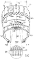
The invention will be better described and better understood with the aid of the description of the non-limiting embodiments illustrated in the accompanying drawings, in which: - Fig. 1 is a perspective view of one preferred embodiment of the tire of the present invention, the tire being shown in a progressive cut-away manner to reveal the reinforcement member of the tire;
- Fig. 2 is a cross-sectional view of the one preferred embodiment of the tire shown in Fig. 1;
- Fig. 3 is an exploded perspective view, in partial vertical section, of the reinforcement member of the tire shown in Fig. 1 prior to assembly of the reinforcement member onto the tire during a tire building process and showing the sinusoidal cords of the plies of the reinforcement member;
- Fig. 4 is an exploded perspective view, in partial vertical section, of the reinforcement member of the tire shown in Fig. 1 after the reinforcement member has been assembled onto the tire during a tire building process and the tire has been disposed in a toroidal shape;
- Fig. 5 is an enlarged perspective view of a portion of the one preferred embodiment of the tire shown in Fig. 1, showing in detail the orientation of the respective cords of the reinforcement member and a bias ply carcass of the tire; and
- Fig. 6 is a cross-sectional view of another preferred embodiment of the tire of the present invention in which the tire includes two pairs of beads.
- The
tire 10 also includes atread portion 24 radially outward of the lateral extents of the first and additional carcass plies. Thetread portion 24 is connected throughshoulder portions 26A, 26B with the pair ofsidewall portions tire 10 additionally includes areinforcement member 28 extending circumferentially of, and disposed radially intermediate, the lateral extents of the first and additional carcasses. As seen in Fig. 5, thereinforcement member 28 includes a plurality ofnon-metallic cords 38 extending parallel to one another and parallel to the mid circumferential plane MD of the tire. Thetire 10 additionally includes abelt package 30 disposed intermediate theadditional carcass 20 and thetread portion 24. - As seen in Figure 6, in another preferred embodiment of the tire of the present invention, an
aircraft tire 110 is of substantially the same general bias construction as thebias tire 10 illustrated in Figure 1-5 except theaircraft tire 110 additionally includes some tire features common to aircraft tires. Specifically, thetire 110 includes a first pair of bead members 112A, 112B and a second pair ofbead members 114A, 114B, each respective pair of bead members being disposed on a respective side of a mid circumferential plane MD of the tire. Thetire 110 also includes a firstupper carcass 116 having a plurality of bias plies and a secondupper carcass 118 having a plurality of bias plies. Each of theupper carcasses - The
tire 110 further includes alower carcass 120 having a plurality of bias plies, a first reinforcement insert 122 and asecond reinforcement insert 124. Atread portion 126 is disposed radially outwardly of the lateral extents of the carcasses. Thetire 110 additionally includes a crownregion reinforcement member 128 extending circumferentially of, and disposed radially intermediate, the lateral extents of the radially innermost one of the upper carcasses 116,118 and thelower carcass 120. Thereinforcement member 128 includes a plurality of non-metallic cords extending parallel to one another and parallel to the mid circumferential plane MD of the tire. - As seen in Figure 1, the bias plies of the
first carcass 16 and the bias plies of theadditional carcass 20 together have a total or cumulative circumferential strength ST as measured parallel to the mid circumferential plane MD of the tire. Thereinforcement member 28 has a circumferential strength SB of between approximately 20 to 150 percent of the total circumferential strength of the first and additional carcasses.
This relationship of the circumferential strength of thereinforcement member 28 relative to the total circumferential strength of the first and additional carcasses is exemplarily illustrated in Fig. 5, in which it can be seen that each cord 22 of theadditional carcass ply 20 is disposed at the same bias angle alpha relative to the mid circumferential plane MD whereas eachcord 38 of thereinforcement member 28 is disposed parallel to the mid circumferential plane MD. - The total circumferential strength of the
first carcass 16 and theadditional carcass 20 may be described as follows:

where:
Σei is the number of cords i₁...in per unit width of each carcass;
ti is the tensile strength of a cord i; and
alphai is the uniform bias angle of a cord i relative to the mid circumferential plane. The reinforcement member includes a plurality of cords and the circumferential strength of the reinforcement member is:
erm is the number of cords per unit width of the reinforcement member; and
trm is the tensile strength of a cord of the reinforcement member, and 0.20 ST < SB < 1.50 ST.
The term "circumferential strength" is intended to mean the strength in tension of the particular tire component and is thus a measure of the ability of the particular tire component to resist radially outward growth. - The
tread portion 24 has a tread width TW as measured laterally perpendicular to the mid circumferential plane MD of the tire which is a measurement of the lateral extent of that area of thetire 10 in contact with the surface at the nominal loaded condition of the tire. Thereinforcement member 28 includes a pair oflateral side portions 32A, 32B and acentral portion 34 disposed intermediate thelateral side portions 32A, 32B and the non-metallic cords of thereinforcement member 28 are arranged in thelateral side portions 32A, 32B and thecentral portion 34 such that at least about 50% of the circumferential strength is provided by thecentral portion 34 of thereinforcement member 28. Thecentral portion 34 of thereinforcement member 28 is disposed substantially laterally coextensive with the middle third of the tread width TW. - The cumulative circumferential strength of each of the
lateral side portions 32A, 32B of thereinforcement member 28 progressively decreases in the laterally outward direction relative to the mid circumferential plane MD. The overall lateral extent of thereinforcement member 28 is less than about 75% of the tread width TW. - The modulus of elasticity of each
non-metallic cord 38 is preferably at a value in the range of between 900 MPa to 7000 MPa and this value is preferably selected to be substantially equal to the modulus of elasticity of a cord of one of the bias plies 18 of the first carcass ply 16 or a cord of one of the bias plies 18 of theadditional carcass ply 20. However, the tire manufacturing and tire performance advantages of the present invention are not solely limited to non-metallic cords having a preferred modulus of elasticity value. For example, a cord comprising polyaramide such as may be obtained commercially under the registered trademark Kevlar may be best suited for a particular tire application although the modulus of elasticity of such a cord may lie outside the preferred modulus of elasticity range. Generally, it is believed that any non-metallic cord material should be acceptable so long as the elongation property of the reinforcing material is basically in the same range as that of the bias plies. - To obtain a cumulative circumferential strength SB of the
reinforcement member 28 having the desired value relative to the value of the cumulative circumferential strength ST of thecarcasses reinforcement member 28 can be configured with any suitable selection of non-metallic cord materials, arrangement of the cords relative to one another, or overall assembled configuration of thereinforcement member 28 on thetire 10 itself. With regard to selection of a non-metallic cord material, nylon or polyester are preferred. Moreover, the cord material is preferably provided as a component of a reinforced ply and an example of a preferred configuration of such a reinforced ply is disclosed in US Patent No. 5,134,024 to Carrier. - The preferred reinforced ply, as disclosed in the Carrier patent and as seen in Figures 3 and 4 hereof, has cords which, in an intermediate, not fully elongated state, have a longitudinal shape which may be referred to as "wavy" or "sinusoidal" or "chevron shaped". As seen in Figure 3, the
reinforcement member 28 is comprised one or more wraps of a reinforcedply 36 formed of a plurality of thecords 38 in an initial "chevron" shape disposed between a pair of rubber skims 40. The rubber skims 40 may themselves maintain thecords 38 in the desired initial "chevron" shape or another means such as a pick yarn arrangement may be used for this purpose. In any event, thecords 38 are maintained in a "chevron" shape in which each cord has a series of linear segments forming vertices with one another although the term "chevron" is to be understood to mean any cord geometry in which the cord is non-linear in one plane, such as thecord 38, or non-linear in more than one plane, such as a cord having an overall helical shape. - The choice of material of the
cords 38, and the specifications of the material (such as denier, twist characteristic, amplitude, or tensile strength), must take into consideration the several transformations which the cords will undergo during the tire building process as well as the performance criteria that is desired for thereinforcement member 28 in the inflated cured tire. For example, the amplitude of the cords 38 (e.g., the spacing between two vertices connected by two linear segments which themselves form a third vertex) is preferably selected to accommodate the "lift" which occurs due to the change in diameter of a green or uncured tire after it has been cured into a cured tire. The "lift" phenomenon will cause further elongation of thecords 38 and, if too large an amplitude is selected, thecords 38 may be already elongated into their linear dispositions prior to curing so that, when the tire expands radially during curing, the cords will be placed in tension to such a degree that the elastic limit of the cords will be prematurely reached during tire use. - The "chevron" shape of the
cords 38 disappears as the reinforcedply 36 is elongated such as occurs after the reinforced ply has been shaped into a toroidal shape. As seen in Figure 4, when the reinforcedply 36 has been thus stretched or elongated, thecords 38 are correspondingly elongated and thereby transform from their "chevron" shape to a substantially linear shape. Moreover, thecord 38 in their substantially linear shape are oriented parallel to the longitudinal extent of the reinforcedply 36 so that, upon assembly of the reinforcedply 36 onto the other tire components, thecords 38 extend parallel to the mid circumferential plane MD - that is, they are at a so-called zero degree bias. - It is also contemplated that other cord constructions may be employed in lieu of a "chevron" shaped cord. For example, the cord construction may feature a resiliently elongatable core made of rubber or another "stretch" type material and an outer covering enclosing the resiliently elongatable core such as, for example, a helically wound thread covering. In any event, a ply such as the reinforced
ply 36 composed of cords which can be elongated without significant impairment of their tensile strength properties permits efficiencies to be achieved in the tire building process. For example, such a reinforced ply can be assembled with other tire components prior to shaping of the uncured tire into a toroidal shape while still providing the reinforcement benefit of a ply having cords extending substantially parallel or parallel to the mid circumferential plane of the tire. - As seen in Figure 1, the
reinforcement member 28 is preferably formed by several layers of the reinforcedply 36 which may be disposed on the underlying tire components by wrapping a single length of the reinforced ply several times about itself or, alternatively, placing several lengths of the reinforced ply in a process in which each length of the reinforced ply is cut and lapped after one or several wraps. Thereinforcement member 28 is preferably disposed between thebelt package 30 which extends in the tread region of thetire 10 and the radially innermost one of thefirst carcass 16 and theadditional carcass 20 and, most preferably, thereinforcement member 28 is disposed in an intra-carcass disposition such as, for example, between thefirst carcass 16 and theadditional carcass 20. - Additionally, while in some tire applications it may be desirable to dispose the
reinforcement member 28 radially outward of all the carcasses, it is believed that, in particular in an aircraft tire application, such a disposition of the reinforcement member may subject the underlying carcasses to a radially inward force in the crown region of the tire would tend to produce unacceptable stress on the carcasses in the shoulder regions of the tire. Accordingly, as seen in Figure 6, thereinforcement member 128 is disposed between the two radiallyinnermost carcasses - With further reference to Figure 2, it can be seen that the
reinforcement member 28 preferably has, in the cured tire, an overall lenticular cross-sectional shape as defined by the reinforced plies 36 with a laterally extending upper side UL and a laterally extending lower side LL radially inward of the upper side UL The lower side LL has a lateral extent less than about 33% of the tread width TW and the upper side UL has a lateral extent less than about 75% of the tread width. Moreover, the upper side UL has a lateral or width extent W(UL) which is preferably greater than the lateral or width extent W(LL) of the lower side and both the upper and lower sides are laterally centered (e.g., they are bisected by the mid circumferential plane MD). - The present invention also contemplates that the overall cross-sectional shape of the reinforcement member 28 (or of all of the reinforcement members, if additional reinforcement members are provided) need not necessarily be centered on the mid circumferential plane MD but may, instead, be in an off-center disposition. For example, if the
tire 10 is specifically designed for use as an aircraft tire to be mounted on a type of landing gear which supports the tire at a significant camber angle, it may be desirable to construct the tire such that the cross-sectional shape of thereinforcement member 28 is at an offset from the midcircumferential plane MD to thereby specifically compensate asymmetric wear of the tire which will occur due to the significant camber position of the tire. - The overall lenticular shape of the
reinforcement member 28 can be achieved by appropriate selection of the materials comprising thecords 38 and/or the rubber skims 40 and appropriate placement of the reinforced plies 36 during the tire building process. Also, thereinforcement member 28 preferably forms a part of the cured tire in such a manner that the upper forms a part of the cured tire in such a manner that the upper side UL extends, in the crown region of thetire 10, radially inward of, and concentric to, theadditional ply 20 with no radial displacement of the additional ply 20 (e.g., theply 20 extends laterally beyond thereinforcement member 28 in opposite lateral directions at the same radial spacing from the tire axis) and the lower side LL extends radially outward of, and concentric to, a portion of thefirst ply 16 in the crown region of the tire which is displaced radially inwardly of the other portions of the first ply extending laterally beyond the lateral endpoints of the lower side. This cured tire configuration is preferred in that it reduces the extent to which thereinforcement member 28 exerts a radially outward force against thetread portion 24 in the crown region of the tire. - The
reinforcement member 28 enhances the ability of thetire 10 to resist circumferential growth in the crown region of the tire by supplementing the circumferential growth restricting properties of thefirst carcass 16 and theadditional carcass 20. The inherent tensile strength of thecords 38 acts to resist any force such as a radially outward force acting on thereinforcement member 28 and thereby impart to the reinforcement member 28 a circumferential growth restricting ability. The bias plies of thefirst carcass 16 and theadditional carcass 20 also resist to some degree the radially outward forces and this resistance, together with the supplemental restraining action of thereinforcement member 28, prevents the crown region of thetire 10 from undesirable circumferential growth which would otherwise cause thetread portion 24 in the crown region to extend radially outwardly of the shoulders of the tire. In a tire with such a radially extended tread portion in the crown region, this radially extending tread portion would undesirably experience a disproportionately higher loading than the shoulder regions of the tread. - In comparison with radial tires, bias tires typically have a transverse profile in their inflated condition which is relatively closer to the "natural contour" of the tire. The transverse radius of the bias tire is thus relatively smaller than the transverse radius of a radial tire. However, the use of a crown reinforcement structure, such as the
reinforcement member 28, permits a bias tire construction with a relatively greater transverse radius. Thetire 10 of the present invention thus represents an improvement over conventional bias tires in that the improved tire exhibits a relatively greater transverse radius than conventional bias tires, thus leading to tread wear improvement and permitting the tire to be constructed with fewer carcass or belt plies and, thus, less weight.
The method to make a composent of the said bias tire comprises - disposing a first carcass on a tire building drum;
- providing a reinforcement member having, in an intermediate configuration of the reinforcement member, at least one non-metallic cord of a sinusoidal shape;
- disposing the reinforcement member on the first carcass situated on the tire building drum;
- disposing an additional carcass on the reinforcement member and the first carcass such that the reinforcement member is disposed between the first carcass and the additional carcass, the first and additional carcass and the reinforcement member thereby forming a green tire component for subsequent shaping in a tire mold, the properties of the non-metallic cord including its sinusoidal shape being selected such that the non-metallic cord elongates into a substantially linear shape during final shaping of the tire.
Claims (11)
- A bias ply tire (10) comprising:
at least one pair of bead members (12A, 12B)
a pair of sidewall portions (14A,14B) each being disposed on a respective side of a mid circumferential plane MD of the tire (10) and having a bead member disposed therein;
a first carcass having at least one bias ply (16),
at least one additional carcass, the additional carcass having at least one bias ply (20), at least the first carcass being anchored to a bead member in one respective sidewall portion and a bead member in the other sidewall portion and each carcass having a lateral extent extending transversely of the mid circumferential plane on both sides thereof with the lateral extent of the additional carcass being radially outward of the lateral extent of the first carcass;
a tread portion (24) radially outward of the lateral extents of the first and additional carcass plies, the tread portion being connected through shoulder portions (26A, 26B) with the pair of sidewall portions; and
a circumferentially extending reinforcement member (28) disposed radially intermediate the lateral extents (28) of the first and additional carcasses, the reinforcement member including at least one non-metallic cord (38) extending substantially parallel to the mid circumferential plane of the tire. - A bias ply tire (10) according to claim 1 wherein the bias plies of the first and additional carcasses have a cumulative circumferential strength as measured parallel to the mid circumferential plane MD of the tire and the reinforcement member has a circumferential strength of between approximately 20 to 150% percent of the cumulative circumferential strength of the first and additional carcasses (16,20).
- A bias ply tire (10) according to claim 2 wherein the tread portion (24) has a tread width TW as measured laterally perpendicular to the mid circumferential plane MD of the tire and the reinforcement member (28) includes a pair of lateral side portions (32A, 32B) and a central portion (34) disposed intermediate the lateral side portions and the cumulative circumferential strength of the reinforcement member is distributed such that at least about 50% of the circumferential strength is provided by the central portion (34) of the reinforcement member (28) and the central portion (34) of the reinforcement member is disposed substantially laterally coextensive with the middle third of the tread width.
- A bias ply tire (10) according to claim 3 wherein the cumulative circumferential strength of each of the lateral side portions (32A, 32B) of the reinforcement member (28) progressively decreases in the laterally outward direction relative to the mid circumferential plane MD of the tire.
- A bias ply tire (10) according to claim 4 wherein the overall lateral extent of the reinforcement member (28) is less than about 75% of the tread width TW.
- A bias ply tire (10) according to claim 2 wherein the reinforcement member (28) includes a plurality of non-metallic cords (38) extending circumferentially in generally parallel orientation to one another.
- A bias ply tire (10) according to claim 6 wherein the non-metallic cords (38) are arranged in an arrangement having an overall lenticular cross-sectional shape.
- A bias ply tire (10) according to claim 7 wherein the arrangement of the non-metallic cords are arranged to define an upper laterally extending side UL and a lower laterally extending side LL radially inward of the upper side UL and extending generally parallel thereto, the lower side having a lateral extent less than about 33% of the tread width and the upper side having a lateral extent less than about 75% of the tread width.
- A bias ply tire (10) according to claim 6 wherein the modulus of elasticity of each non-metallic cord (38) is substantially equal to the modulus of elasticity of a cord of a carcass ply (16, 20).
- A bias ply tire (10) according to claim 1 wherein the tire is an aircraft tire and further comprising a second pair of bead members, each respective pair of bead members being disposed in a respective one of the pair of sidewall portions.
- A method of making a component of a bias ply tire, comprising:- disposing a first carcass (16) on a tire building drum;- providing a reinforcement member (28) having, in an intermediate configuration of the reinforcement member, at least one non-metallic cord (38) of a sinusoidal shape ;- disposing the reinforcement member (28) on the first carcass (16) situated on the tire building drum; and- disposing an additional carcass (20) on the reinforcement member (28) and the first carcass (16) such that the reinforcement member is disposed between the first carcass (16) and the additional carcass (20), the first and additional carcass and the reinforcement member thereby forming a green tire component for subsequent shaping in a tire mold, the properties of the non-metallic cord including its sinusoidal shape being selected such that the non-metallic cord elongates into a substantially linear shape during final shaping of the tire.
Applications Claiming Priority (2)
| Application Number | Priority Date | Filing Date | Title |
|---|---|---|---|
| US27569494A | 1994-07-15 | 1994-07-15 | |
| US275694 | 1994-07-15 |
Publications (3)
| Publication Number | Publication Date |
|---|---|
| EP0692394A2 true EP0692394A2 (en) | 1996-01-17 |
| EP0692394A3 EP0692394A3 (en) | 1996-04-03 |
| EP0692394B1 EP0692394B1 (en) | 1999-08-18 |
Family
ID=23053423
Family Applications (1)
| Application Number | Title | Priority Date | Filing Date |
|---|---|---|---|
| EP95109330A Expired - Lifetime EP0692394B1 (en) | 1994-07-15 | 1995-06-16 | Bias tire having an improved crown reinforcement arrangement |
Country Status (7)
| Country | Link |
|---|---|
| US (1) | US5759314A (en) |
| EP (1) | EP0692394B1 (en) |
| JP (1) | JP3169792B2 (en) |
| KR (1) | KR100339947B1 (en) |
| CN (1) | CN1053622C (en) |
| CA (1) | CA2153949C (en) |
| ES (1) | ES2135630T3 (en) |
Families Citing this family (16)
| Publication number | Priority date | Publication date | Assignee | Title |
|---|---|---|---|---|
| FR2823698B1 (en) * | 2001-04-19 | 2004-05-07 | Michelin Soc Tech | AIR TIRES FOR AIRCRAFT |
| ATE332814T1 (en) * | 2001-10-29 | 2006-08-15 | Michelin Soc Tech | TIRES WITH DOUBLE HALF-CASSIS LAYERS AND LOWER REINFORCEMENT BELT |
| US6622764B2 (en) * | 2002-02-01 | 2003-09-23 | The Goodyear Tire & Rubber Company | Underlay structure for increased crown stiffening |
| JP4381982B2 (en) * | 2002-08-09 | 2009-12-09 | ソシエテ ド テクノロジー ミシュラン | Tires for vehicles with two wheels |
| WO2004065141A1 (en) * | 2003-01-17 | 2004-08-05 | Societe De Technologie Michelin | Mounted sets for a plane, wheels and tyres |
| BRPI0414490B1 (en) * | 2003-09-18 | 2013-02-19 | pneumatic. | |
| JP4561633B2 (en) * | 2003-10-01 | 2010-10-13 | 横浜ゴム株式会社 | Manufacturing method of radial tire for construction vehicle |
| US20090178750A1 (en) * | 2008-01-15 | 2009-07-16 | Maurice Taylor | Multiple bead radial tire |
| FR2933031B1 (en) * | 2008-06-30 | 2011-08-19 | Michelin Soc Tech | SUMMIT FOR TIRE AIRCRAFT |
| CN102317088B (en) * | 2009-02-17 | 2013-11-20 | 株式会社普利司通 | Tire and tire manufacturing method |
| KR101069017B1 (en) * | 2010-02-19 | 2011-09-29 | 금호타이어 주식회사 | Tread Reinforcement Cord Structure for Aircraft Bias Tires |
| FR2962371B1 (en) * | 2010-07-07 | 2014-03-21 | Michelin Soc Tech | TOP REINFORCEMENT FOR AIR TIRE |
| BR112014010181B1 (en) * | 2011-11-07 | 2020-07-07 | Compagnie Générale Des Establissements Michelin | tire with multiple bead cores and closure insert |
| JP2014061065A (en) * | 2012-09-20 | 2014-04-10 | Casio Comput Co Ltd | Connection structure of piece body |
| WO2015134181A1 (en) * | 2014-03-01 | 2015-09-11 | Bridgestone Americas Tire Operations, Llc | Tire assembly including an inner tire and an outer tire |
| JP2018075898A (en) * | 2016-11-08 | 2018-05-17 | 東洋ゴム工業株式会社 | Pneumatic tire |
Citations (2)
| Publication number | Priority date | Publication date | Assignee | Title |
|---|---|---|---|---|
| US1188062A (en) | 1914-12-02 | 1916-06-20 | Goodrich Co B F | Flat-section pneumatic tire. |
| US5134024A (en) | 1987-11-30 | 1992-07-28 | Compagnie Generale Des Etablissements Michelin - Michelin & Cie | Reinforcing ply for a penumatic tire containing reinforcing fibers in a sinusoidal pattern |
Family Cites Families (25)
| Publication number | Priority date | Publication date | Assignee | Title |
|---|---|---|---|---|
| US1309308A (en) * | 1919-07-08 | Vehicie-tibe | ||
| US1023666A (en) * | 1910-09-21 | 1912-04-16 | Lucien Liais | Cover for pneumatic tires. |
| US1165631A (en) * | 1913-06-06 | 1915-12-28 | Eureka Tire Company | Vehicle-tire. |
| US1386599A (en) * | 1920-09-04 | 1921-08-09 | James H Courvoisier | Pneumatic tire |
| US1779391A (en) * | 1927-12-13 | 1930-10-21 | Goodyear Tire & Rubber | Method of constructing pneumatic tires |
| US2348350A (en) * | 1940-10-26 | 1944-05-09 | Goodrich Co B F | Tire |
| US2388421A (en) * | 1942-06-23 | 1945-11-06 | Gen Tire & Rubber Co | Pneumatic tire |
| FR1008744A (en) * | 1948-05-19 | 1952-05-21 | Kleber Colombes | Improvements made to flexible structures such as tire casings |
| IT479133A (en) * | 1951-03-21 | |||
| DE1141551B (en) * | 1956-07-02 | 1962-12-20 | Continental Gummi Werke Ag | Pneumatic vehicle tires |
| FR1214031A (en) * | 1958-02-21 | 1960-04-05 | Gummiwerke Fulda K G A A | Cover for pneumatic tires |
| NL269768A (en) * | 1960-10-04 | |||
| NL269848A (en) * | 1960-10-07 | |||
| BE639433A (en) * | 1962-10-31 | |||
| US3780782A (en) * | 1969-01-23 | 1973-12-25 | Uniroyal Inc | Tire with belt between bias carcass plies |
| US3620279A (en) * | 1969-07-15 | 1971-11-16 | Orszagos Gumiipari Vallalat | Pneumatic tires |
| US3685564A (en) * | 1969-11-17 | 1972-08-22 | John C Smithkey Jr | Pneumatic tire |
| US4050973A (en) * | 1971-07-08 | 1977-09-27 | Uniroyal Inc. | Methods of building zero degree belted tires, using high soft stretch belt-forming tapes |
| SE448155B (en) * | 1974-12-28 | 1987-01-26 | Bridgestone Tire Co Ltd | PNEUMATIC DECK FOR CLEANING VEHICLES. |
| US4142568A (en) * | 1977-02-23 | 1979-03-06 | The Goodyear Tire & Rubber Company | Bias tire with embedded wire breakers |
| US4098315A (en) * | 1977-03-09 | 1978-07-04 | Uniroyal, Inc. | Belted pneumatic tires with zero degree breaker reinforcement, and method of building such tires |
| JPS53136202A (en) * | 1977-04-28 | 1978-11-28 | Bridgestone Corp | Pneumatic tyre for heavy duty and high speed use |
| JPS588406A (en) * | 1981-07-02 | 1983-01-18 | Bridgestone Corp | Pneumatic biased tire for heavy load |
| JPS6226102A (en) * | 1985-07-26 | 1987-02-04 | Bridgestone Corp | Antinoise pneumatic bias tire provided with reinforced plies |
| ES2038527T3 (en) * | 1990-11-03 | 1993-07-16 | Continental Aktiengesellschaft | TIRE FOR BICYCLES. |
-
1995
- 1995-04-20 JP JP09551795A patent/JP3169792B2/en not_active Expired - Lifetime
- 1995-06-16 EP EP95109330A patent/EP0692394B1/en not_active Expired - Lifetime
- 1995-06-16 ES ES95109330T patent/ES2135630T3/en not_active Expired - Lifetime
- 1995-06-26 CN CN95107674A patent/CN1053622C/en not_active Expired - Fee Related
- 1995-07-14 US US08/502,723 patent/US5759314A/en not_active Expired - Lifetime
- 1995-07-14 CA CA002153949A patent/CA2153949C/en not_active Expired - Fee Related
- 1995-07-14 KR KR1019950021245A patent/KR100339947B1/en not_active IP Right Cessation
Patent Citations (2)
| Publication number | Priority date | Publication date | Assignee | Title |
|---|---|---|---|---|
| US1188062A (en) | 1914-12-02 | 1916-06-20 | Goodrich Co B F | Flat-section pneumatic tire. |
| US5134024A (en) | 1987-11-30 | 1992-07-28 | Compagnie Generale Des Etablissements Michelin - Michelin & Cie | Reinforcing ply for a penumatic tire containing reinforcing fibers in a sinusoidal pattern |
Also Published As
| Publication number | Publication date |
|---|---|
| JP3169792B2 (en) | 2001-05-28 |
| KR100339947B1 (en) | 2002-10-31 |
| CN1053622C (en) | 2000-06-21 |
| CA2153949C (en) | 2004-12-28 |
| KR960003996A (en) | 1996-02-23 |
| ES2135630T3 (en) | 1999-11-01 |
| EP0692394B1 (en) | 1999-08-18 |
| EP0692394A3 (en) | 1996-04-03 |
| CA2153949A1 (en) | 1996-01-16 |
| CN1119598A (en) | 1996-04-03 |
| JPH0858309A (en) | 1996-03-05 |
| US5759314A (en) | 1998-06-02 |
Similar Documents
| Publication | Publication Date | Title |
|---|---|---|
| EP0908329B1 (en) | Reinforcing fabric for an article made from elastometric material and corresponding article comprising this fabric | |
| EP0335588B1 (en) | Radial tyre | |
| EP0692394B1 (en) | Bias tire having an improved crown reinforcement arrangement | |
| US5779829A (en) | Pneumatic tire having a single carcass ply reinforced with metallic cords, a high ending ply, turnup and locked bead construction | |
| EP1800902A1 (en) | Pneumatic radial tire | |
| US5115853A (en) | Pneumatic tire with belt overlay structure reinforced with low denier nylon cords | |
| EP2261059B1 (en) | Pneumatic tire with an overlay reinforcement | |
| US5054532A (en) | Pneumatic tires with wavy or zigzag cord ply between belt and carcass | |
| EP0344086A2 (en) | Pneumatic tire | |
| JPH04328003A (en) | Pneumatic radial tire | |
| US4945967A (en) | Reinforcing armouring of tires for vehicle wheels | |
| JP7475108B2 (en) | Lighter aircraft tires | |
| EP0542567B1 (en) | Pneumatic tyre | |
| KR960011997B1 (en) | Pneumatic tire for heavy equipment | |
| JP2783826B2 (en) | Pneumatic tire | |
| RU2749204C1 (en) | Breaker construction for tire | |
| EP0463273B1 (en) | Radial ply tire | |
| JP4118608B2 (en) | Pneumatic radial tire for aircraft and manufacturing method thereof | |
| JP2021091396A (en) | Shear band | |
| JP2018034789A (en) | Reduced weight aircraft tire | |
| JP5961349B2 (en) | Pneumatic radial tire | |
| US4216813A (en) | Radial tire with a belt structure of different reinforcement cords | |
| JP2004256102A (en) | Aircraft tire with improved bead structure | |
| JPH03157204A (en) | Pneumatic radial tire | |
| JP2021091397A (en) | Shear band |
Legal Events
| Date | Code | Title | Description |
|---|---|---|---|
| PUAI | Public reference made under article 153(3) epc to a published international application that has entered the european phase |
Free format text: ORIGINAL CODE: 0009012 |
|
| AK | Designated contracting states |
Kind code of ref document: A2 Designated state(s): ES FR GB IT |
|
| PUAL | Search report despatched |
Free format text: ORIGINAL CODE: 0009013 |
|
| AK | Designated contracting states |
Kind code of ref document: A3 Designated state(s): ES FR GB IT |
|
| 17P | Request for examination filed |
Effective date: 19961004 |
|
| 17Q | First examination report despatched |
Effective date: 19980224 |
|
| GRAG | Despatch of communication of intention to grant |
Free format text: ORIGINAL CODE: EPIDOS AGRA |
|
| GRAG | Despatch of communication of intention to grant |
Free format text: ORIGINAL CODE: EPIDOS AGRA |
|
| GRAH | Despatch of communication of intention to grant a patent |
Free format text: ORIGINAL CODE: EPIDOS IGRA |
|
| GRAH | Despatch of communication of intention to grant a patent |
Free format text: ORIGINAL CODE: EPIDOS IGRA |
|
| GRAA | (expected) grant |
Free format text: ORIGINAL CODE: 0009210 |
|
| AK | Designated contracting states |
Kind code of ref document: B1 Designated state(s): ES FR GB IT |
|
| ET | Fr: translation filed | ||
| ITF | It: translation for a ep patent filed | ||
| REG | Reference to a national code |
Ref country code: ES Ref legal event code: FG2A Ref document number: 2135630 Country of ref document: ES Kind code of ref document: T3 |
|
| PLBE | No opposition filed within time limit |
Free format text: ORIGINAL CODE: 0009261 |
|
| STAA | Information on the status of an ep patent application or granted ep patent |
Free format text: STATUS: NO OPPOSITION FILED WITHIN TIME LIMIT |
|
| 26N | No opposition filed | ||
| REG | Reference to a national code |
Ref country code: GB Ref legal event code: IF02 |
|
| PGFP | Annual fee paid to national office [announced via postgrant information from national office to epo] |
Ref country code: ES Payment date: 20050708 Year of fee payment: 11 |
|
| PG25 | Lapsed in a contracting state [announced via postgrant information from national office to epo] |
Ref country code: ES Free format text: LAPSE BECAUSE OF NON-PAYMENT OF DUE FEES Effective date: 20060617 |
|
| REG | Reference to a national code |
Ref country code: ES Ref legal event code: FD2A Effective date: 20060617 |
|
| PGFP | Annual fee paid to national office [announced via postgrant information from national office to epo] |
Ref country code: GB Payment date: 20120613 Year of fee payment: 18 |
|
| GBPC | Gb: european patent ceased through non-payment of renewal fee |
Effective date: 20130616 |
|
| PG25 | Lapsed in a contracting state [announced via postgrant information from national office to epo] |
Ref country code: GB Free format text: LAPSE BECAUSE OF NON-PAYMENT OF DUE FEES Effective date: 20130616 |
|
| PGFP | Annual fee paid to national office [announced via postgrant information from national office to epo] |
Ref country code: IT Payment date: 20140620 Year of fee payment: 20 |
|
| PGFP | Annual fee paid to national office [announced via postgrant information from national office to epo] |
Ref country code: FR Payment date: 20140609 Year of fee payment: 20 |