EP0692198B1 - Method and apparatus for heating and sterilizing food - Google Patents
Method and apparatus for heating and sterilizing food Download PDFInfo
- Publication number
- EP0692198B1 EP0692198B1 EP95109355A EP95109355A EP0692198B1 EP 0692198 B1 EP0692198 B1 EP 0692198B1 EP 95109355 A EP95109355 A EP 95109355A EP 95109355 A EP95109355 A EP 95109355A EP 0692198 B1 EP0692198 B1 EP 0692198B1
- Authority
- EP
- European Patent Office
- Prior art keywords
- food
- heating
- sterilizing
- chamber
- steam
- Prior art date
- Legal status (The legal status is an assumption and is not a legal conclusion. Google has not performed a legal analysis and makes no representation as to the accuracy of the status listed.)
- Expired - Lifetime
Links
Images


Classifications
-
- A—HUMAN NECESSITIES
- A23—FOODS OR FOODSTUFFS; TREATMENT THEREOF, NOT COVERED BY OTHER CLASSES
- A23L—FOODS, FOODSTUFFS, OR NON-ALCOHOLIC BEVERAGES, NOT COVERED BY SUBCLASSES A21D OR A23B-A23J; THEIR PREPARATION OR TREATMENT, e.g. COOKING, MODIFICATION OF NUTRITIVE QUALITIES, PHYSICAL TREATMENT; PRESERVATION OF FOODS OR FOODSTUFFS, IN GENERAL
- A23L3/00—Preservation of foods or foodstuffs, in general, e.g. pasteurising, sterilising, specially adapted for foods or foodstuffs
- A23L3/02—Preservation of foods or foodstuffs, in general, e.g. pasteurising, sterilising, specially adapted for foods or foodstuffs by heating materials in packages which are progressively transported, continuously or stepwise, through the apparatus
- A23L3/08—Preservation of foods or foodstuffs, in general, e.g. pasteurising, sterilising, specially adapted for foods or foodstuffs by heating materials in packages which are progressively transported, continuously or stepwise, through the apparatus with packages on a revolving platform
-
- A—HUMAN NECESSITIES
- A23—FOODS OR FOODSTUFFS; TREATMENT THEREOF, NOT COVERED BY OTHER CLASSES
- A23L—FOODS, FOODSTUFFS, OR NON-ALCOHOLIC BEVERAGES, NOT COVERED BY SUBCLASSES A21D OR A23B-A23J; THEIR PREPARATION OR TREATMENT, e.g. COOKING, MODIFICATION OF NUTRITIVE QUALITIES, PHYSICAL TREATMENT; PRESERVATION OF FOODS OR FOODSTUFFS, IN GENERAL
- A23L3/00—Preservation of foods or foodstuffs, in general, e.g. pasteurising, sterilising, specially adapted for foods or foodstuffs
- A23L3/16—Preservation of foods or foodstuffs, in general, e.g. pasteurising, sterilising, specially adapted for foods or foodstuffs by heating loose unpacked materials
- A23L3/18—Preservation of foods or foodstuffs, in general, e.g. pasteurising, sterilising, specially adapted for foods or foodstuffs by heating loose unpacked materials while they are progressively transported through the apparatus
- A23L3/185—Preservation of foods or foodstuffs, in general, e.g. pasteurising, sterilising, specially adapted for foods or foodstuffs by heating loose unpacked materials while they are progressively transported through the apparatus in solid state
-
- A—HUMAN NECESSITIES
- A23—FOODS OR FOODSTUFFS; TREATMENT THEREOF, NOT COVERED BY OTHER CLASSES
- A23L—FOODS, FOODSTUFFS, OR NON-ALCOHOLIC BEVERAGES, NOT COVERED BY SUBCLASSES A21D OR A23B-A23J; THEIR PREPARATION OR TREATMENT, e.g. COOKING, MODIFICATION OF NUTRITIVE QUALITIES, PHYSICAL TREATMENT; PRESERVATION OF FOODS OR FOODSTUFFS, IN GENERAL
- A23L3/00—Preservation of foods or foodstuffs, in general, e.g. pasteurising, sterilising, specially adapted for foods or foodstuffs
- A23L3/001—Details of apparatus, e.g. for transport, for loading or unloading manipulation, pressure feed valves
-
- A—HUMAN NECESSITIES
- A23—FOODS OR FOODSTUFFS; TREATMENT THEREOF, NOT COVERED BY OTHER CLASSES
- A23L—FOODS, FOODSTUFFS, OR NON-ALCOHOLIC BEVERAGES, NOT COVERED BY SUBCLASSES A21D OR A23B-A23J; THEIR PREPARATION OR TREATMENT, e.g. COOKING, MODIFICATION OF NUTRITIVE QUALITIES, PHYSICAL TREATMENT; PRESERVATION OF FOODS OR FOODSTUFFS, IN GENERAL
- A23L3/00—Preservation of foods or foodstuffs, in general, e.g. pasteurising, sterilising, specially adapted for foods or foodstuffs
- A23L3/003—Control or safety devices for sterilisation or pasteurisation systems
-
- A—HUMAN NECESSITIES
- A23—FOODS OR FOODSTUFFS; TREATMENT THEREOF, NOT COVERED BY OTHER CLASSES
- A23L—FOODS, FOODSTUFFS, OR NON-ALCOHOLIC BEVERAGES, NOT COVERED BY SUBCLASSES A21D OR A23B-A23J; THEIR PREPARATION OR TREATMENT, e.g. COOKING, MODIFICATION OF NUTRITIVE QUALITIES, PHYSICAL TREATMENT; PRESERVATION OF FOODS OR FOODSTUFFS, IN GENERAL
- A23L3/00—Preservation of foods or foodstuffs, in general, e.g. pasteurising, sterilising, specially adapted for foods or foodstuffs
- A23L3/02—Preservation of foods or foodstuffs, in general, e.g. pasteurising, sterilising, specially adapted for foods or foodstuffs by heating materials in packages which are progressively transported, continuously or stepwise, through the apparatus
- A23L3/04—Preservation of foods or foodstuffs, in general, e.g. pasteurising, sterilising, specially adapted for foods or foodstuffs by heating materials in packages which are progressively transported, continuously or stepwise, through the apparatus with packages on endless chain or band conveyors
Definitions
- This invention relates to method and apparatus for heating and sterilizing food and, more particularly, to food heating and sterilizing method and apparatus adapted to heat and sterilize food which is in open or unsealed condition.
- Japanese Patent Laid-Open Publication No. 4-370081 discloses a method of filling boiled rice into containers, heating and sterilizing it under pressure and thereafter sealing the containers under an aseptic condition.
- a variety of sterilizing apparatuses are already known for successively feeding food into a sealed sterilizing chamber for heating and sterilizing the food under at high temperature or at high temperature and under high pressure, including those disclosed in Japanese Patent Laid-Open Publication Nos. 49-71177, 51-42391 and 64-51069.
- a convey or means has to be arranged within the food heating and sterilizing chamber of the apparatus in order to advance the food fed to the apparatus further into the chamber.
- a conveyor means arranged within a sealed chamber can make the entire configuration of the apparatus rather complicated and disadvantageous from the viewpoint of maintaining the chamber in an aseptic state.
- a heating chamber filled with hot and pressurized steam and a cooling chamber held to a temperature lower than that of the heating chamber are connected with each other by way of a sealing gate, which is opened at regular intervals to allow the food sterilized in the heating chamber to be advanced into the cooling chamber.
- steam in the heating chamber can be condensed to water to accumulate in the heating chamber due to the cold air flow from the cooling chamber.
- the water to be drained can boil up abruptly or bump (reboiling phenomenon non is occurs) when the sealing gate is opened and the inner pressure of the heating chamber is lowered, so that the food in the chamber is wetted and degraded.
- the above object and other objects can be achieved by providing method and apparatus for heating and sterilizing food comprising steps of filling a container having an opening with solid food, moving the food into a sealable sterilizing chamber and applying straightly flowing steam to said solid food.
- an apparatus for heating and sterilizing food comprising a heating and sterilizing chamber for heating and sterilizing food under pressure higher than the atmospheric pressure, said food being contained in a container having an opening and being successively fed in, characterized in that said heating and sterilizing chamber is provided with a steam supply means for supplying steam and a drain means from draining away unnecessary fluid out of it.
- an apparatus for heating and sterilizing food comprising a food feeding section in communication with the atmosphere, a pressure upward regulating chamber, a heating and sterilizing chamber for heating and sterilizing food under pressure higher than the atmospheric pressure, a cooling chamber for cooling the heated and sterilized food, a pressure downward regulating chamber and a delivery section for discharging food arranged successively and connected by way of respective sealing gates, said food being contained in rigid containers having an opening and moved successively from said food feeding section to said heating and sterilizing chamber, said food feeding section, said heating and sterilizing chamber, said cooling chamber and said delivery section being arranged perpendicularly relative to or in parallel with each other and said food feeding section, said pressure upward regulating chamber, said heating and sterilizing chamber, said cooling chamber, said pressure downward regulating chamber and said delivery section on being provided at respective upstream portions thereof with a pusher device for pushing downstream said rigid containers, each of pusher devices having a stroke equal to or greater than the width of a rigid container, and said apparatus further comprising steam supply means for supplying
- This invention is intended to heat and sterilize solid food that does not deteriorates if directly put into contact with hot and pressurized steam.
- Solid food items to which the present invention is applicable include boiled rice, cooked rice such as pilaf, noodles such as "udon", “soba” and Chinese noodles, pasta such as macaroni and spaghetti, beans such as soy beans, peas such as green peas, vegetable such as potato, carrot and sorghum, meat such as beef and pork, and processed food such as meat balls, fried bean curd or fried "kamaboko".
- the present invention is particularly effective for food items having void spaces when contained in containers.
- This food heating and sterilizing apparatus 300 is an autoclave. It comprises a heating and sterilizing chamber 301 disposed within the apparatus and provided at a lower portion thereof with a shelf 302 having an upper plate, which is a meshy member.
- the upper plate of the shelf 302 carries thereon a cylindrical container 303 with a diameter of about 140 millimeter and a height of about 55 millimeter.
- the cylindrical container 303 is provided at the bottom thereof with holes (not shown) having a diameter of about 2 millimeter and arranged with intervals of 3 millimeter.
- the heating and sterilizing chamber 301 is additionally provided at an upper portion thereof with a steam supply pipe 305 having a plurality of steam blow out ports 304.
- the steam supply pipe 305 is connected to a steam generating means (not shown) such as a boiler and supplied steam into the heating and sterilizing chamber 301.
- the steam blow out ports 304 are located substantially right above the cylindrical container 303 placed on the shelf 302 so that steam blown out of the blow out ports 304 may directly and vertically hit the food 306 contained in the cylindrical container 303.
- the heating and sterilizing chamber 302 is further provided at a central position of the bottom opposite to the upper plate of said shelf with an exhaust port 307 and at peripheral positions of the bottom with steam supply ports 308.
- Said container 303 is made of a thermally resistive material. Specific materials that can be used for the container include plastic materials, ceramic materials and metals, although the container is preferably a plastic container having no holes at the bottom if a closure is directly fitted thereto to produce a sealed product immediately after the sterilizing operation. While the container 303 may not necessarily be cylindrical, preferably it is tray-shaped or cup-shaped and has an opening having an area equal to or greater than that of the bottom so that the food in the container may be evenly exposed to steam. Furthermore, the food is preferably made very flat in the container so that it may be exposed to steam more uniformly.
- food heating and sterilizing apparatus 300 comprises a single shelf 302 and a single con tainer 303 arranged on the shelf 302, a plurality of containers 303 may alternatively be arranged on the shelf 302 or, still alternatively, two or more shelves may be provided in the apparatus, each carrying thereon one or more than one containers 303.
- blow out ports 304 While any appropriate number of blow out ports 304 may be arranged in the apparatus, the number of blow out ports 304 may preferably made equal to the number of containers 303, if more than one containers 303 are provided in the heating and sterilizing chamber 301, so that they show a one-to-one correspondence.
- a single blow out port 304 may operate efficiently for sterilization it a plurality of containers 303 are made to move within the heating and sterilizing chamber 301.
- a steam blow out port may alternatively be arranged below the shelf 302 so that steam may hit the food in the container 303 from under.
- a tall cylindrical container having a plurality of holes along the lateral wall thereof may be used and steam blow out ports may be arranged on the lateral wall of the autoclave so that steam may horizontally hit the lateral wall of the container. If such is the case, the efficiency of the sterilizing operation of the apparatus can be improved by arranging an exhaust port at a location opposite to the blow out ports on the lateral wall of the autoclave. Still alternatively, a steam blow out port may be arranged below the container such that steam may hit the lateral wall of the autoclave having a horizontally disposed cylindrical from and an exhaust port may be arranged an the bottom of the autoclave at a position directly below the container. Then, consequently steam proceeds straightly downward from above and vertically hit the food.
- steam includes saturated steam, a superheated steam and any other types of steam that can be used for heating and sterilizing food.
- the container 303 containing food (boiled rice) 306 therein was placed on the shelf 302 and steam was fed into the sterilizing chamber 301 through the steal supply port 308.
- the supplied steam pressure was regulated to a level higher than the specified pressure of the sterilizing chamber 301 by 0.5 to 1.5kg/cm 2 . More specifically, steam was generated by a boiler (not shown) to a pressure level of 7kg/cm 2 , which was reduced to 3kg/cm 2 by means of a pressure reducing valve (not shown), before it was fed into the sterilizing chamber 301 through the steam supply port 308. At this time, the exhaust port 307 was held open so that any air remaining in the sterilizing chamber 301 was forced out of the sterilizing chamber 301 through the exhaust port 307.
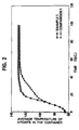
- Table 1 shows the overage of the F 0 values observed in the void spaces of the boiled rice 306 and the deviation when the F 0 value of the atmosphere in the sterilizing chamber 301 was 10. Throughout this specification, the deviation is defined as the difference between the maximum and minimum values at each point of observation.
- the container 303 containing boiled rice 306 therein was placed on the shelf 302 and steam was supplied into the sterilizing chamber 301 through the steam supply port 308 until any remaining air was forced out through the exhaust port 307 and the sterilizing chamber 301 was filled with steam. At this time (or about 10 seconds later), the exhaust port 307 was closed. The supply of steam of was continued thereafter until the inside temperature of the sterilizing chamber rose to about 130°C, which temperature was then maintained.
- Fig. 2 illustrates the average temperature rise observed in the experiment. This operation was repeated for three times.
- Table 1 shows the average of the F 0 values observed in the void spaces of the cooked rise 306 and the deviation when the F 0 value of the atmosphere in the sterilizing chamber 301 was 10.
- This example is same as Experimental Example 1 except that the container did not have any hole at the bottom and the exhaust port 307 has kept open after the start of supplying steam through the steam blow out port 304.
- Fig. 3 illustrates the average temperature rise observed in void spaces in the experiment after the start of supplying vapor. This operation was repeated for three times.
- Table 2 shows the average of the F 0 values observed in the void spaces of the cooked rise 306 and the deviation when the F 0 value of the atmosphere in the sterilizing chamber 301 was 10.
- This example is same as Experimental Example 2 except that the exhaust port 307 was closed at the start of supplying steam through the vapor blow out port 304.
- Fig. 3 illustrates the average temperature rise observed in void spaces in the experiment after the start of supplying vapor.
- Table 2 shows the average of the F 0 values observed in the void spaces of the cooked rise 306 and the deviation when the F 0 value of the atmosphere in the sterilizing chamber 301 was 10.
- This comparative example is same as Comparative Example 1 except that the container did not have any hole at the bottom
- Fig. 3 illustrates the average temperature rise observed in void spaces in the experiment after the start of supplying vapor. This operation was repeated for three times.
- Table 2 shows the average of the F 0 values observed in the void spaces of the cooked rise 306 and the deviation when the F 0 value of the atmosphere in the sterilizing chamber 301 was 10.
- the food sterilizing apparatus 100 of this embodiment is designed to heat and sterilize solid food to be packed in retort pouches at a later stage, such as boiled rice, cooked noodle, the solid ingredients of stew or curry (e.g., vegetables) with containing directly in rigid trays 90 or other containers.
- Fig. 5 schematically illustrates a tray adapted for use in the embodiment.
- the tray 90 is hollow and cylindrical and typically made of metal such as stainless steel. It has an open top 93 and a closed bottom and is designed to carry a predetermined volume of food (e.g., one portion of boiled rice). As a plurality of trays 90 successively pass through the food sterilizing apparatus 100, the food in the trays are heated and sterilized.
- the bottom plate 91 of the tray 90 is provided with a number of small through bores 92 distributed over the entire area of the bottom plate 91.
- the size of the through bores 92 are so selected that the food placed on the bottom plate 92 of the tray 90 may not fall therethrough. Steam or other heating and sterilizing fluid may freely pass the bottom plate through the small through bores 92 to get to the entire surface of the food on the bottom plate 91.
- the main body of the food sterilizing apparatus 100 has a configuration as described below.
- the food sterilizing apparatus 100 comprises, from the upstream end thereof, a food feeding section 1 held in communication with the atmosphere and designed to receive trays 90 containing food for sterilisation, a heating and sterilizing chamber 3 for heating and sterilizing food under pressure higher than the atmospheric pressure, a cooling chamber 4 for cooling the heated and sterilized food and a delivery section 6 for discharging the cooled food out of the food sterilizing apparatus 100.
- the food feeding section 1 by turn comprises a receiving section 11 located at the upstream extremity of the apparatus in order to receive food containing trays 90 and a preheating chamber 12 located downstream relative to the receiving section 11 in order to preheat the food in the trays 90 under the atmospheric pressure.
- a pressure upward regulating chamber 2 in disposed upstream relative to the heating and sterilizing chamber 3 and separated therefrom by a second gate valve 20, whereas a pressure downward regulating chamber 5 is disposed upstream relative to the delivery section 6 and separated therefrom by a fifth gate valve 50.
- the preheating chamber 12 located in a downstream area of the food feeding section is connected to the pressure upward regulating chamber 2 located in an upstream area of the heating and sterilizing chamber 3 by way of a first gate valve 10.
- the heating and sterilizing chamber 3 is connected at a downstream portion thereof with an upstream area of the cooling chamber 4 via a third gate valve 30.
- the cooling chamber 4 is connected at a downstream portion thereof with the pressure downward regulating chamber 5 located upstream relative to the delivery section 6.
- a pair of received trays 90, 90 containing food to be sterilized are placed in juxtaposition in the receiving section 11 of the food feeding section 1 by a feeding means (not shown).
- the receiving section 11 is provided at an upstream portion thereof with a first pusher device 13 for moving downstream (in direction X) the paired trays 90, 90.
- the first pusher device 13 is provided with a T-shaped extendible pusher rod 13a, which pusher rod 13a is extendible and has a stroke that enables it to push the juxtaposed trays 90, 90 downstream (in direction X) in the food feeding section 1 to the downstream end of the preheating chamber 12.
- the preheating chamber 12 is provided outside the downstream end thereof with a second pusher device 14. More specifically, the second pusher device 14 is arranged opposite to the pressure upward regulating chamber 2 with the downstream end of the preheating chamber 12 disposed therebetween. Like the first pusher device 13, the second pusher device 14 is provided with a T-shaped extendible pusher rod 14a, which pusher rod 14a is extendible in a direction (in direction Y) perpendicular to the general direction of movement of trays 90, 90 toward the pressure upward regulating chamber 2.
- the rod 14a has a stroke that enables it go into the downstream end of the preheating chamber 12 and push the juxtaposed trays 90, 90 that arrive the downstream end of the preheating chamber 12 under the pushing effect of the first pusher device 13 this time in a single row along the direction Y onto a turn table 24 arranged in the pressure upward regulating chamber 2.
- the preheating chamber 12 is open to the atmosphere and therefore held under the atmospheric pressure and has a shape and dimensions adapted to guide a pair of juxtaposed trays 90, 90 downstream.
- the preheating chamber 12 is additionally provided with a preheating means 15 as schematically illustrated in Fig. 4.
- the preheating means 15 supplies the preheating chamber 12 with steam, while deaerating the preheating chamber 12.
- the pressure upward regulating chamber 2 is connected at an upper portion thereof with a steam supply pipe 21 for feeding steam.
- the steam supply pipe 21 is by turn connected to a steam supply source (not shown) by way of a control valve 22 and a steam tank (pressurized fluid tank) for storing steam.
- a steam supply source not shown
- a steam tank pressurized fluid tank
- the steam tank 23 is designed to temporarily store steam from the steam supply source and preferably has a capacity 5 to 50 times, more preferably 10 to 30 times greater than the capacity of the pressure upward regulating chamber 2.
- the pressure of steam in the steam tank 23 is preferably between 0.5 and 3.0kg/cm 2 and more preferably between 1.0 and 2.5kg/cm 2 (as observed by a pressure gauge).
- the control valve 22 is designed to control the supply of steam to the pressure upward regulating chamber 2 by its ON/OFF action realized under the control of a control device (not shown).
- a turn table 24 is arranged within the pressure upward regulating chamber and rotatable around a vertical axis Z (See Figs. 6 and 7).
- the turn table 24 itself is a substantially rectangularly parallelepipedic cabinet-like hollow body which is open at a longitudinal smaller lateral side and dimensioned so as to contain a pair of trays in a row. Thus, a pair of trays 90, 90 can move into and out of the turn table 24 through the open side (open area 24b).
- a substantially circular hole 24a is cut through the lateral wall opposite to the open side of the turn table 24.
- the top plate 24c of the turn table 24 covers the open tops of the trays 90, 90 housed in the turn table 24. More specifically, the top plate 24c is located between the open end 21a of the steam supply pipe 21 in the pressure upward regulating chamber 2 and the open tops 93, 93 of the trays 90, 90 housed in the turn table 24 so that it effectively prevents steam blown out of the open end 21a of the pipe 21 from directly entering the trays 90, 90 through the open tops 93, 93.
- the turn table 24 is provided at the bottom thereof with a rotary shaft 25 so that it may rotate around said rotary shaft 25 by a predetermined angle. More specifically, the turn table 24 rotates by 90° between a first position where the open side area 24b faces the preheating chamber 12 and a second position where the open side area 24b faces the heating and sterilizing chamber 3 (Figs. 6 and 7).
- a pair of trays 90, 90 can be housed in the turn table 24 as they are pushed forward toward the pressure upward regulating chamber 2 (in direction Y) by the second pusher device 14, whereas, in the second position, the pair of trays 90, 90 housed in the turn table 24 can be pushed into the heating and sterilizing chamber 3 from the turn table 24 through the open side area 24b thereof by a third pusher device 26, which will be described hereinafter.
- a third pusher device 26 for pushing out a pair of trays 90, 90 housed in the turn table 24 into the heating and sterilizing chamber 3 when the turn table 24 is disposed in its second position as shown in Fig. 7.
- the third pusher device 26 is provided with an extendible pusher rod 26a, which is so shaped and dimensioned that it can move through the hole 24a cut through a wall of the turn table 24.
- the extendible pusher rod 26a has a stroke long enough to push out a pair of trays 90, 90 housed in the turn table 24 and arranged in a row as shown in Fig. 7 into the heating and sterilizing chamber 3.
- the heating and sterilizing chamber 3 is located down-stream relative to the pressure upward regulating chamber 2 and has a substantially cylindrical and oblong inner space, where a pair of rails 31a and 31b are arranged in parallel with a given distance separating them from each other and extend longitudinally over the entire length of the chamber.
- the pair of trays 90, 90 pushed out of the pressure upward regulating chamber 2 and forced into the heating and sterilizing chamber 3 by the third pusher device 26 are then moved downstream on the rails 31a and 31b, the distance separating the rails 31a and 31b being so selected for them to appropriately support the bottoms of the traveling trays 90, 90.
- the rails 31a and 31b are provided with a number of guide members 35 arranged with a predetermined distance separating any adjacent ones so that the trays 90, 90 can safely and smoothly advance along the rails 31a and 31b as shown in Figs. 6 and 7.
- the rails 31a and 31b and the guide members 35 constitute a tray transfer route for advancing trays into the heating and sterilizing chamber 3 in a row.
- the heating and sterilizing chamber 3 is provided with a heating and sterilizing means 32 for maintaining the inner pressure and the temperature of the heating and sterilizing chamber 3 to predetermined levels.
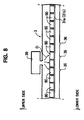
- the heating and sterilizing means 32 which is schematically illustrated in Fig. 4, comprises a steam supply means 39 for feeding steam into the heating and sterilizing chamber 3 and an exhaust means 36 for drawing unnecessary fluid out of the heating and sterilizing chamber 3 (See Fig. 8).
- the steam supply means 39 is connected to an upper portion of the heating and sterilizing chamber 3 and designed to apply steam to the trays 90, 90 traveling on the rails 31a, 31a from above.
- the exhaust means is in fact an exhaust port 36 arranged at the bottom of the heating and sterilizing chamber 3.
- the exhaust port 36 may be provided with a check valve.
- the steam supply means 39 supplies steam with pressure higher than the predetermined inner pressure of the heating and sterilizing chamber 3 by 0.05 to 0.3kg/cm 2 .
- the exhaust means 36 at the bottom of the heating and sterilizing chamber operates to draw unnecessary fluid such as air containing steam and drain water out of the heating and sterilizing chamber and, at the same time, maintains the internal pressure of the heating and sterilizing chamber to a predetermined level.
- Steam coming from the steam supply means 39 and immediately before entering the heating and sterilizing chamber preferably shows a pressure level higher than the predetermined internal pressure level of the heating and sterilizing chamber by 0.05 - 0.3kg/cm 2 , more preferably by 0.1 - 0.2kg/cm 2 . If the pressure difference is smaller than 0.05kg/cm 2 , the pressure of the entering steam is not sufficiently high for controlling the internal pressure of the heating and sterilizing chamber and the exhaust means 36 does not operate satisfactorily. If, on the other hand, the pressure difference is greater than 0.3kg/cm 2 , steam may flow violently to raise the temperature of the steam supply means 39 at the opening thereof and deteriorate the food.
- the inner pressure and the temperature of the heating and sterilizing chamber 3 are preferably held to 0.45-2.65kg/cm 2 , preferably to 1.00-2.15kg/cm 2 (as observed with a gauge), and 120-135°C respectively.
- the heating and sterilizing chamber 3 is provided at the downstream end thereof with a turn table 33 similar to the one arranged in the pressure upward regulating chamber 2.
- the heating and sterilizing chamber 3 is additionally provided outside and at the side thereof disposed opposite to the cooling chamber 4 with a fourth pusher device 34 similar to the third pusher device 26.
- the turn table 33 and the pusher device 34 operate like the turn table 24 and the third pusher device 26 respectively.
- the heating and sterilizing chamber 3 is connected at the downstream end thereof to the upstream end of the cooling chamber 4 arranged in parallel with the heating and sterilizing chamber 3 by way of the third gate valve 30.
- the cooling chamber 4 is provided at the upstream end thereof with a turn table 41 similar to the one arranged in the pressure upward regulating chamber 2.
- the cooling chamber 4 is additionally provided near the upstream end thereof with a fifth pusher device 42 similar to the third pusher device 26.
- the turn table 41 and the pusher device 42 operate like the turn table 24 and the third pusher device 26 respectively.
- the cooling chamber 4 has a configuration similar to that of the heating and sterilizing chamber 3. It has a substantially cylindrical and oblong inner space, where a pair of rails 46a and 46b are arranged in parallel with a given distance separating them from each other and extend longitudinally over the entire length of the chamber.
- the pair of trays carried in a row by the turn table 41 are advanced downstream on the rails 46a and 46b, the distance separating the rails 46a and 46b being so selected for them to appropriately support the bottoms of the traveling trays 90, 90.
- the rails 46a and 46b are provided with a number of guide members similar to the guide members 35 described above and arranged with a predetermined distance separating any adjacent ones so that the trays 90, 90 can safely and smoothly advance along the rails 46a and 46b.
- the cooling chamber 4 is provided with a cooling means 43 for maintaining the inner pressure and the temperature of the cooling chamber 4 to predetermined respective levels.
- the cooling means 43 which is schematically illustrated in Fig. 4, feed air at 80°C to the cooling chamber 4 to maintain the inner pressure and the temperature of the cooling chamber 4 typically to 1.8kg/cm 2 and 80°C respectively.
- the cooling chamber 4 is provided at the downstream end thereof with a turn table 44 similar to the one arranged in the pressure upward regulating chamber 2.
- the cooling chamber 4 is additionally provided near the downstream end thereof with a sixth pusher device 45 similar to the third pusher device 26.
- the turn table 44 and the sixth pusher device 45 operate like the turn table 24 and the third pusher device 26 respectively.
- the pressure downward regulating chamber 5 is arranged in parallel with and connected to the downstream and of the cooling chamber 4 by way of a gate valve 40 and has a configuration similar to that of the pressure upward regulating chamber 2. More specifically, it is provided with a turn table 51 for receiving a pair of trays 90, 90 arranged in a row and coming from the cooling chamber 4 and a seventh pusher device 52 for moving the trays 90, 90 housed in the turn table 51 in a row into the delivery section 6.
- the pressure downward regulating chamber 5 differs from the pressure upward regulating chamber 2 in that the steam supply pipe 21 of the latter is replaced by an air supply pipe (not shown).
- the delivery section 6 is provided at the downstream side thereof with a conveying means such as a belt conveyor.
- a conveying means such as a belt conveyor.
- the sterilized food that has been moved to the delivery section in trays 90 is then sent to a packaging station (not shown).
- the delivery section 6, the conveying means 70 and the packaging station are housed in a clean room.
- the packaging station the food is taken out of the trays 90 and packed in sterilized containers which are packages for the finishing products, the containers are then airtightly sealed after, if necessary, having been filled with sterilized liquid food.
- steam includes saturated steam, super heated steam and other vapors used for heating and sterilizing the food.
- the above described food sterilizing apparatus 100 operates in a manner as described below.
- the food contained in trays supplied by a supply means are received by the receiving section 11 of the food feeding section 1 such that a pair of juxtaposed trays 90, 90 are arranged in the receiving section 11 at a time.
- the first pusher device 13 is operated to move the juxtaposed trays 90, 90 to the downstream end of the preheating chamber 12 by means of the pusher rod 13a. Since steam is supplied to the inside of the preheating chamber 12 by the steam supply means 15, the air that fills the gaps in the food housed in the trays 90, 90 is replaced by steam to preheat the food while the food is traveling forward in the preheating chamber 12.
- the first gate valve 10 is opened to make the pressure upward regulating chamber 2 communicate with the preheating chamber 12, while the second gate valve 20 is kept closed, and the turn table 24 is put to its first position as shown in Figs. 4 and 6.
- the pusher rod 14a of the second pusher device 14 is extended to push the trays 90, 90 arranged in juxtaposition at the downstream end of the preheating chamber 12 into the turn table 24 in a row running along the pressure upward regulating chamber 2.
- the pusher rod 14a is contracted and the turn table 24 is rotated counterclockwise by 90° to its second position as illustrated in Fig. 7.
- the first gate valve 10 is shut to bring the pressure upward regulating chamber 2 into a closed state and then the control valve 22 is opened to allow steam to flow into the pressure upward regulating chamber 2 from the tank 23 until the inner pressure of the pressure upward regulating chamber becomes equal to that of the heating and sterilizing chamber 3. Since the top plate 24c of the turn table 24 covers the openings 93, 93 of the trays 90, 90, steam bursting out of the open end 21a of the pipe 21 would not directly hit the food in the trays 90, 90 and blow it away.
- the second gate valve 20 is opened and the third pusher device 26 is operated to extend the pusher rod 26a, which by turn pushes the trays 90, 90 in the turn table 24 into the tray transfer route in the heating and sterilizing chamber 3. Since the heating and sterilizing chamber 3 is already filled with trays on the transfer route as a result of preceding cycles, the frontmost pair of trays on the transfer route are pushed into the turn table 33 by the newly arrived pair of trays 90, 90 that are pushed onto the transfer route. The open lateral side of the turn table 33 is directed to the transfer route of the heating and sterilizing chamber 3 to receive the pair of trays 90, 90 pushed out of the heating and sterilizing chamber 3.
- the turn table 33 is rotated clockwise by 90° and the third gate valve 30 is opened, while the fourth pusher device 34 is operated to extend the pusher rod 34a and push the trays 90, 90 in the turn table 33 toward the cooling chamber 4 until the trays are put into the turn table 41 having its open lateral side directed to the fourth pusher device 34.
- the second gate valve 20 is closed immediately and the inner pressure of the pressure upward regulating chamber 2 is reduced to the level of the atmospheric pressure by a pressure reducing means (not shown) such as a valve. Then, the first gate valve 10 is opened and the succeeding pair of trays 90, 90 are moved into the pressure upward regulating chamber 2.
- steam coming from the steam supply means 39 hits the row of trays 90 traveling on the rails 31a, 31b from above. More specifically, steam hits the trays 90 from above substantially vertically as shown by arrow D in Fig. 8 and then runs out of the trays through the holes arranged at the bottom thereof. Thereafter, the steam passes through the exhaust port 36 arranged at the bottom of the heating and sterilizing chamber 3 and goes out of the chamber 3. Note that any drain water produced in the heating and sterilizing chamber 3 and air coming from the cooling chamber are also forced out of the chamber by the flow of steam.
- the third gate valve 30 is closed and the turn table 41 is rotated counterclockwise by 90° until the open lateral side of the turn table 41 is directed to the transfer route of the cooling chamber 4.
- the fifth pusher device 42 is operated to extend the pusher rod 42a and push the pair of trays 90, 90 on the turn table 41 onto the transfer route in the cooling chamber 4. Since the cooling chamber 4 is already filled with trays on the transfer route as a result of preceding cycles, the frontmost pair of trays on the transfer route are pushed into the turn table 44 having its open lateral side directed to the transfer route by the newly arrived pair of trays 90, 90 that are pushed onto the transfer route by the fifth pusher device 42 as in the case of the heating and sterilizing chamber 3.
- the turn table 44 is rotated clockwise by 90°.
- the fifth gate valve 50 is closed and, while keeping the open lateral side of the turn table 51 directed to the cooling chamber 4 (as shown in Fig. 1), air is suppled to the pressure downward regulating chamber 5 from the air supply pipe until the inner pressure of the pressure downward regulating chamber 5 gets to the level of that of the cooling chamber 4.
- the fourth gate valve 40 is opened to make the pressure downward regulating chamber 5 communicate with the cooling chamber 4 and the sixth pusher device 45 is operated to extend the pusher rod 45a and push the trays 90, 90 housed in the turn table 44 in a row into the turn table 51.
- the pusher rod 45a of the sixth pusher device 45 is contracted to its original state and the turn table 51 is rotated counterclockwise by 90° so that its open lateral side of the turn table is directed to the delivery section 6.
- the fourth gate valve 40 is shut to bring the pressure downward regulating chamber 5 into a closed state and then the pressure reducing means (not shown) such as a valve is opened to allow the inner pressure of the pressure downward regulating chamber 5 to fall to the level of the atmospheric pressure.
- the fifth gate valve 50 is opened and the seventh pusher device 52 is operated to extend the pusher rod 52a and push the trays 90, 90 housed in the turn table 51 in a row into the delivery section 6.
- the trays 90, 90 moved into the delivery section 6 are then transferred to a subsequent station (not shown) for packaging by means of the belt conveyor 70.
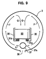
- Figs. 9 and 10 illustrate a modified steam supply means 32.
- This modified steam supply means 32 comprises a steam supply pipe 37 arranged blow a pair of rails 31a, 31b for moving trays 90 and drain holes 38 arranged at the bottom of the heating and sterilizing chamber 3.
- the steam supply pipe 37 extends substantially along the entire length of the heating and sterilizing chamber 3 and is provided with a plurality of steam blow out ports 37a.
- the drain holes 38 are used to drain unnecessary fluid out of the heating and sterilizing chamber 3.
- the steam supply means operates in a manner as described below.
- the steam supply pipe 37 is connected to a steam source and a pressure reducing valve (not shown) and steam is supplied therethrough with a predetermined pressure level. Steam arriving the steam supply pipe 37 is then laterally blown out into the heating and sterilizing chamber 3 through the steam blow out ports 37a along arrows E to collide with and run upward along the lateral wall of the cylindrical heating and sterilizing chamber 3 as indicated by arrows F. The flow of steam in then turned downward above the transfer route of the tray 90 and hits the tray 90 from above substantially vertically. Thereafter, the flow of steam passes through the hole 90 of the tray 90 and runs out of the heating and sterilizing chamber 3 through the drain holes 38 at the bottom of the chamber with drain water, if any.
- a third embodiment of food sterilizing apparatus will be described by referring to Fig. 11 Since the food sterilizing apparatus 200 of this embodiment is substantially similar to the food sterilizing apparatus 100 of the second embodiment, only the difference between the two embodiments will be described hereinafter and the components similar to those of the first embodiment will be denoted by the same reference numerals that are prefixed by 2 or 20 and their descriptions will be omitted.
- the food sterilizing apparatuses 100 and 200 are different in the way how the food feeding sections 1 and 201, the heating and sterilizing chambers 3 and 203 and the cooling chambers 4 and 204 are connected.
- the food feeding section 1, the heating and sterilizing chamber 3 and the cooling chamber 4 are arranged and connected in such a way that the directions along which trays are moved respectively in the food fooding section 1, the heating and sterilizing chamber 3 and the cooling chamber 4 are parallel to each other and, therefore, a pair of trays are transferred forward at the junctions by means of a pair of pusher devices (e.g., 14 and 26) and a turn table (e.g., 24) such that they appear like a "crank" there.
- a pair of pusher devices e.g., 14 and 26
- a turn table e.g., 24
- the food feeding section 201 and the heating and sterilizing chamber 203 are arranged perpendicularly relative to each other so that trays moving therethrough turns rectangularly at the junction thereof.
- the heating and sterilizing chamber 203 and the cooling chamber 204 are arranged perpendicularly relative to each other so that trays moving therethrough turns rectangularly again at the junction thereof.
- the pressure upward regulating chamber 202 does not require a turn table for the operation of the food sterilizing apparatus 200 while the junctions require only single pusher devices (214, 234 respectively) in order to transfer trays forward.
Description
- This invention relates to method and apparatus for heating and sterilizing food and, more particularly, to food heating and sterilizing method and apparatus adapted to heat and sterilize food which is in open or unsealed condition.
- Conventionally solid food is generally heated and sterilized under pressure after the food is filled in sealed containers. However, with such a conventional method of sterilization, the food can be susceptible to bear an odor specific to retort treatment because it is mostly contained in such sealed containers and/or take a particularly long processing time because the food has to be heated with air contained in sealed containers.
- A number of different methods have been proposed to solve this problem. For example, Japanese Patent Laid-Open Publication No. 4-370081 discloses a method of filling boiled rice into containers, heating and sterilizing it under pressure and thereafter sealing the containers under an aseptic condition.
- On the other hand, a variety of sterilizing apparatuses are already known for successively feeding food into a sealed sterilizing chamber for heating and sterilizing the food under at high temperature or at high temperature and under high pressure, including those disclosed in Japanese Patent Laid-Open Publication Nos. 49-71177, 51-42391 and 64-51069. With any of these sterilizing apparatuses, however, a convey or means has to be arranged within the food heating and sterilizing chamber of the apparatus in order to advance the food fed to the apparatus further into the chamber. A conveyor means arranged within a sealed chamber can make the entire configuration of the apparatus rather complicated and disadvantageous from the viewpoint of maintaining the chamber in an aseptic state.
- With the method disclosed in Japanese Patent Laid-Open publication No. 4-370081, the food is simply sterilized in a pressurized atmosphere and, when solid food such as a lump of boiled rice containing a large number of small void spaces therein is to be sterilized, air remaining in those spaces can prevent any quick and efficient sterilization from taking place.
- Additionally, air remaining in small void spaces can interfere with uniform temperature rise (distribution) in the food. Thus, if excessive heat is applied to the food to raise the temperature of the center of the food to a sufficiently high level for sterilization, the surface of the food can become discolored and the food itself can be degraded through the excessive heating.
- On the other hand, a variety of food heating and sterilizing apparatuses have been proposed to successively move packages of food into a sealed and heated sterilizing chamber without arranging a conveyor means in the chamber in view of the problems that may arise in known food heating and sterilizing apparatuses comprising a sterilizing chamber in which a conveyor means is installed. For example, U.S. Patent Application No.08/395,111 filed on February 27, 1995 and assigned to the assignee of the present application, discloses a food heating and sterilizing apparatus comprising a heating vessel (a heater) for sterilizing packages of food fed successively thereto at high temperature and under high pressure. In the disclosed apparatus, a heating chamber filled with hot and pressurized steam and a cooling chamber held to a temperature lower than that of the heating chamber are connected with each other by way of a sealing gate, which is opened at regular intervals to allow the food sterilized in the heating chamber to be advanced into the cooling chamber. With this arrangement, low temperature air can flow from the cooling chamber into the heating chamber whenever the sealing gate is opened to interfere with the conduction of heat to the food and consequently lower the efficiency with which the food is heated.
- Additionally, steam in the heating chamber can be condensed to water to accumulate in the heating chamber due to the cold air flow from the cooling chamber. The water to be drained can boil up abruptly or bump (reboiling phenomenon non is occurs) when the sealing gate is opened and the inner pressure of the heating chamber is lowered, so that the food in the chamber is wetted and degraded.
- It is the object of the invention to provide a method and an apparatus for effectively heating and sterilizing food within a short period of time without discoloring and degrading the food.
- This object is fulfilled by a method having the features disclosed in
claim 1 and an apparatus disclosed inclaim 5. Preferred embodiments are defined in the dependent subclaims. - According to the invention, the above object and other objects can be achieved by providing method and apparatus for heating and sterilizing food comprising steps of filling a container having an opening with solid food, moving the food into a sealable sterilizing chamber and applying straightly flowing steam to said solid food.
- According to the invention, there is also provided an apparatus for heating and sterilizing food comprising a heating and sterilizing chamber for heating and sterilizing food under pressure higher than the atmospheric pressure, said food being contained in a container having an opening and being successively fed in, characterized in that said heating and sterilizing chamber is provided with a steam supply means for supplying steam and a drain means from draining away unnecessary fluid out of it.
- According to the invention, there is also provided an apparatus for heating and sterilizing food comprising a food feeding section in communication with the atmosphere, a pressure upward regulating chamber, a heating and sterilizing chamber for heating and sterilizing food under pressure higher than the atmospheric pressure, a cooling chamber for cooling the heated and sterilized food, a pressure downward regulating chamber and a delivery section for discharging food arranged successively and connected by way of respective sealing gates, said food being contained in rigid containers having an opening and moved successively from said food feeding section to said heating and sterilizing chamber, said food feeding section, said heating and sterilizing chamber, said cooling chamber and said delivery section being arranged perpendicularly relative to or in parallel with each other and said food feeding section, said pressure upward regulating chamber, said heating and sterilizing chamber, said cooling chamber, said pressure downward regulating chamber and said delivery section on being provided at respective upstream portions thereof with a pusher device for pushing downstream said rigid containers, each of pusher devices having a stroke equal to or greater than the width of a rigid container, and said apparatus further comprising steam supply means for supplying steam and a drain means for draining unnecessary fluid out of the heating and sterilizing chamber and said containers have an opening facing upward and being provided at the bottom thereof with a hole so sized as not to allow the food to pass therethrough, steam supplied from said steam supply means being straightly applied to the food in each container and thereafter flowing downward through the hole thereof.
-
- Fig. 1 is a schematic longitudinal cross sectional view of a first embodiment of apparatus for heating and sterilizing the food according to the invention.
- Fig. 2 is a graph showing some of the results of an experiment of sterilizing food obtained by using the apparatus of Fig. 1.
- Fig. 3 is a graph showing some of the results of other experiments of sterilizing food obtained by using the apparatus of Fig. 1.
- Fig. 4 is a schematic plan view of a second embodiment of the apparatus for heating and sterilizing food according to the invention, showing its overall configuration.
- Fig. 5 is a schematic perspective view of a tray for containing food that can be used for second through embodiments of apparatus for heating and sterilizing food according to the invention.
- Fig. 6 is a schematic perspective view of the turn table arranged in the pressure upward regulating chamber of the second embodiment of the apparatus heating and sterilizing food according to the invention, showing the turn table placed in a first position.
- Fig. 7 is a schematic perspective view of the turn table arranged in the pressure upward regulating chamber of the second embodiment of the apparatus for heating and sterilizing food according to the invention, showing the turn table placed in a second position.
- Fig. 8 is a schematic partial longitudinal cross sectional view of the heating and sterilizing chamber of the second embodiment of the apparatus for heating and sterilizing food according to the invention, showing the heating and sterilizing means.
- Fig. 9 is a schematic transversal cross sectional view of the heating and sterilizing chamber of the second embodiment of the apparatus for heating and sterilizing food according to the invention, showing a modified form of the heating and sterilizing means.
- Fig. 10 is a schematic partial longitudinal cross sectional view of the heating and sterilizing chamber of the second embodiment of the apparatus for heating and sterilizing food according to the invention, showing a modified form of the heating and sterilizing means.
- Fig. 11 is a schematic plan view of a third embodiment of the apparatus for heating and sterilizing food according to the invention, showing its overall configuration.
-
- Now, the invention will be described by referring to the accompanying drawings that illustrate preferred embodiments of the invention.
- This invention is intended to heat and sterilize solid food that does not deteriorates if directly put into contact with hot and pressurized steam. Solid food items to which the present invention is applicable, include boiled rice, cooked rice such as pilaf, noodles such as "udon", "soba" and Chinese noodles, pasta such as macaroni and spaghetti, beans such as soy beans, peas such as green peas, vegetable such as potato, carrot and sorghum, meat such as beef and pork, and processed food such as meat balls, fried bean curd or fried "kamaboko". The present invention is particularly effective for food items having void spaces when contained in containers.
- Firstly a first embodiment of food heating and sterilizing
apparatus 300 will be described. This food heating and sterilizingapparatus 300 is an autoclave. It comprises a heating and sterilizingchamber 301 disposed within the apparatus and provided at a lower portion thereof with ashelf 302 having an upper plate, which is a meshy member. The upper plate of theshelf 302 carries thereon acylindrical container 303 with a diameter of about 140 millimeter and a height of about 55 millimeter. Thecylindrical container 303 is provided at the bottom thereof with holes (not shown) having a diameter of about 2 millimeter and arranged with intervals of 3 millimeter. The heating and sterilizingchamber 301 is additionally provided at an upper portion thereof with asteam supply pipe 305 having a plurality of steam blow outports 304. Thesteam supply pipe 305 is connected to a steam generating means (not shown) such as a boiler and supplied steam into the heating and sterilizingchamber 301. The steam blow outports 304 are located substantially right above thecylindrical container 303 placed on theshelf 302 so that steam blown out of the blow outports 304 may directly and vertically hit thefood 306 contained in thecylindrical container 303. The heating and sterilizingchamber 302 is further provided at a central position of the bottom opposite to the upper plate of said shelf with anexhaust port 307 and at peripheral positions of the bottom withsteam supply ports 308. - Said
container 303 is made of a thermally resistive material. Specific materials that can be used for the container include plastic materials, ceramic materials and metals, although the container is preferably a plastic container having no holes at the bottom if a closure is directly fitted thereto to produce a sealed product immediately after the sterilizing operation. While thecontainer 303 may not necessarily be cylindrical, preferably it is tray-shaped or cup-shaped and has an opening having an area equal to or greater than that of the bottom so that the food in the container may be evenly exposed to steam. Furthermore, the food is preferably made very flat in the container so that it may be exposed to steam more uniformly. - While the embodiment of food heating and sterilizing
apparatus 300 comprises asingle shelf 302 and asingle con tainer 303 arranged on theshelf 302, a plurality ofcontainers 303 may alternatively be arranged on theshelf 302 or, still alternatively, two or more shelves may be provided in the apparatus, each carrying thereon one or more than onecontainers 303. - While any appropriate number of blow out
ports 304 may be arranged in the apparatus, the number of blow outports 304 may preferably made equal to the number ofcontainers 303, if more than onecontainers 303 are provided in the heating and sterilizingchamber 301, so that they show a one-to-one correspondence. A single blow outport 304 may operate efficiently for sterilization it a plurality ofcontainers 303 are made to move within the heating and sterilizingchamber 301. - While the above embodiment of food heating and sterilizing
apparatus 300 is provided with anexhaust port 307 disposed below theshelf 302, a steam blow out port may alternatively be arranged below theshelf 302 so that steam may hit the food in thecontainer 303 from under. - Alternatively, a tall cylindrical container having a plurality of holes along the lateral wall thereof may be used and steam blow out ports may be arranged on the lateral wall of the autoclave so that steam may horizontally hit the lateral wall of the container. If such is the case, the efficiency of the sterilizing operation of the apparatus can be improved by arranging an exhaust port at a location opposite to the blow out ports on the lateral wall of the autoclave. Still alternatively, a steam blow out port may be arranged below the container such that steam may hit the lateral wall of the autoclave having a horizontally disposed cylindrical from and an exhaust port may be arranged an the bottom of the autoclave at a position directly below the container. Then, consequently steam proceeds straightly downward from above and vertically hit the food.
- For the purpose of the invention, in the specification, "steam" includes saturated steam, a superheated steam and any other types of steam that can be used for heating and sterilizing food.
- The above embodiment of food heating and sterilizing
apparatus 300 will now be described by way of a number of Experimental Examples. - The
container 303 containing food (boiled rice) 306 therein was placed on theshelf 302 and steam was fed into the sterilizingchamber 301 through thesteal supply port 308. The supplied steam pressure was regulated to a level higher than the specified pressure of the sterilizingchamber 301 by 0.5 to 1.5kg/cm2. More specifically, steam was generated by a boiler (not shown) to a pressure level of 7kg/cm2, which was reduced to 3kg/cm2 by means of a pressure reducing valve (not shown), before it was fed into the sterilizingchamber 301 through thesteam supply port 308. At this time, theexhaust port 307 was held open so that any air remaining in the sterilizingchamber 301 was forced out of the sterilizingchamber 301 through theexhaust port 307. When the sterilizingchamber 301 was filled with steam (or about 1 second later), both theexhaust port 307 and thesteam supply port 308 were closed. Thereafter, steam was introduced into the sterilizingchamber 301 through the steam blow outport 304 until the temperature in the sterilizing chamber was raised to about 130°C and held to that level until the F0 value of the atmosphere in the sterilizingchamber 301 got to 10. After the start of the supply of steam, the temperature of the void gaps in the boiledrice 306 in thecontainer 303 was observed at nine (9) points by means of thermocouples (not shown). Fig. 2 illustrates the average temperature rise observed in the experiment. This operation was repeated for three times. Table 1 shows the overage of the F0 values observed in the void spaces of the boiledrice 306 and the deviation when the F0 value of the atmosphere in the sterilizingchamber 301 was 10. Throughout this specification, the deviation is defined as the difference between the maximum and minimum values at each point of observation. - Steam was made to blow downward from the steam blow out
port 304 and hit the food vertically. The steam that had hit the food vertically then passed through the void spaces in the lump of the boiled rice and drove out the air contained in the spaces. Thus, the food was made to directly contact with steam even at the center of the lump so that the inside temperature of the lump of the food smoothly and uniformly rose with the temperature in the remaining parts of the food. Consequently, the food was not discolored nor deteriorated by superheating and any defective sterilization of the rice due to insufficient heating was avoided. - The
container 303 containing boiledrice 306 therein was placed on theshelf 302 and steam was supplied into the sterilizingchamber 301 through thesteam supply port 308 until any remaining air was forced out through theexhaust port 307 and the sterilizingchamber 301 was filled with steam. At this time (or about 10 seconds later), theexhaust port 307 was closed. The supply of steam of was continued thereafter until the inside temperature of the sterilizing chamber rose to about 130°C, which temperature was then maintained. - Under this condition, the temperature of the void gaps in the boiled
rice 306 in thecontainer 303 was observed at nine (9) points by means of thermocouples (not shown). Fig. 2 illustrates the average temperature rise observed in the experiment. This operation was repeated for three times. Table 1 shows the average of the F0 values observed in the void spaces of the cookedrise 306 and the deviation when the F0 value of the atmosphere in the sterilizingchamber 301 was 10.F0 value in spaces of rice when F0 in the atmosphere was 10 average value deviation Experimental Example 1 9.51 9.44 9.52 9.37 9.42 9.63 9.63 9.65 9.83 9.50 9.63 9.56 9.51 9.32 9.10 9.47 9.13 9.59 9.74 0.73 9.61 9.22 9.19 9.13 9.31 9.36 9.81 9.59 9.62 Comparative Example 1 4.32 7.18 7.98 7.56 4.76 3.49 6.12 7.92 8.11 6.05 7.33 4.59 6.16 6.96 6.26 4.19 4.25 8.01 6.28 5.18 8.67 4.28 4.89 5.91 5.09 7.91 6.94 6.97 7.56 - As seen from Fig. 2 showing the curves representing the temperature rise observed at nine points in void spaces of the boiled rice, the temperature in void spaces rose more smoothly in Experimental Example 1 than in Comparative Example 1. Table 1 shows that the F0 values at the observation points are substantially equal to each other in Experimental Example 1, whereas they substantially varies in Comparative Example 1.
- This example is same as Experimental Example 1 except that the container did not have any hole at the bottom and the
exhaust port 307 has kept open after the start of supplying steam through the steam blow outport 304. - Fig. 3 illustrates the average temperature rise observed in void spaces in the experiment after the start of supplying vapor. This operation was repeated for three times. Table 2 shows the average of the F0 values observed in the void spaces of the cooked
rise 306 and the deviation when the F0 value of the atmosphere in the sterilizingchamber 301 was 10. - This example is same as Experimental Example 2 except that the
exhaust port 307 was closed at the start of supplying steam through the vapor blow outport 304. - Fig. 3 illustrates the average temperature rise observed in void spaces in the experiment after the start of supplying vapor. Table 2 shows the average of the F0 values observed in the void spaces of the cooked
rise 306 and the deviation when the F0 value of the atmosphere in the sterilizingchamber 301 was 10. - This comparative example is same as Comparative Example 1 except that the container did not have any hole at the bottom
- Fig. 3 illustrates the average temperature rise observed in void spaces in the experiment after the start of supplying vapor. This operation was repeated for three times. Table 2 shows the average of the F0 values observed in the void spaces of the cooked
rise 306 and the deviation when the F0 value of the atmosphere in the sterilizingchamber 301 was 10.F0 value in spaces of rice when F0 in the atmosphere was 10 average value deviation Experimental Example 2 7.18 8.90 8.54 9.30 9.38 9.43 9.30 7.28 8.11 7.23 9.01 6.98 9.25 9.09 9.32 7.99 7.67 9.11 8.37 2.67 7.09 8.08 6.95 9.59 9.62 7.55 9.37 7.23 7.60 Example 3 6.86 6.28 6.37 9.22 8.99 6.50 8.28 7.09 6.98 7.40 2.94 Comparative Example 2 0.61 7.08 1.06 9.06 7.03 8.71 3.83 0.22 1.72 4.37 8.84 - As seen from Fig. 3 showing the curves representing the average temperature rise observed at nine points in void spaces of the boiled rice, the temperature in void spaces rose more smoothly in Experimental Examples 2 and 3 than in Comparative Example 2. Table 2 shows that the deviations in Experimental Examples 2 and 3 are smaller that that in Comparative Example 2.
- Now, a second embodiment will be described by referring to Figs. 4 through 10, where the food sterilizing apparatus is generally denoted by
reference numeral 100. - The
food sterilizing apparatus 100 of this embodiment is designed to heat and sterilize solid food to be packed in retort pouches at a later stage, such as boiled rice, cooked noodle, the solid ingredients of stew or curry (e.g., vegetables) with containing directly inrigid trays 90 or other containers. Fig. 5 schematically illustrates a tray adapted for use in the embodiment. Thetray 90 is hollow and cylindrical and typically made of metal such as stainless steel. It has an open top 93 and a closed bottom and is designed to carry a predetermined volume of food (e.g., one portion of boiled rice). As a plurality oftrays 90 successively pass through thefood sterilizing apparatus 100, the food in the trays are heated and sterilized. - The
bottom plate 91 of thetray 90 is provided with a number of small throughbores 92 distributed over the entire area of thebottom plate 91. The size of the through bores 92 are so selected that the food placed on thebottom plate 92 of thetray 90 may not fall therethrough. Steam or other heating and sterilizing fluid may freely pass the bottom plate through the small throughbores 92 to get to the entire surface of the food on thebottom plate 91. - The main body of the
food sterilizing apparatus 100 has a configuration as described below. Referring to Fig. 4, thefood sterilizing apparatus 100 comprises, from the upstream end thereof, afood feeding section 1 held in communication with the atmosphere and designed to receivetrays 90 containing food for sterilisation, a heating and sterilizingchamber 3 for heating and sterilizing food under pressure higher than the atmospheric pressure, acooling chamber 4 for cooling the heated and sterilized food and adelivery section 6 for discharging the cooled food out of thefood sterilizing apparatus 100. - The
food feeding section 1 by turn comprises a receivingsection 11 located at the upstream extremity of the apparatus in order to receivefood containing trays 90 and a preheatingchamber 12 located downstream relative to the receivingsection 11 in order to preheat the food in thetrays 90 under the atmospheric pressure. A pressure upward regulatingchamber 2 in disposed upstream relative to the heating and sterilizingchamber 3 and separated therefrom by asecond gate valve 20, whereas a pressure downward regulatingchamber 5 is disposed upstream relative to thedelivery section 6 and separated therefrom by afifth gate valve 50. - The preheating
chamber 12 located in a downstream area of the food feeding section is connected to the pressure upward regulatingchamber 2 located in an upstream area of the heating and sterilizingchamber 3 by way of afirst gate valve 10. The heating and sterilizingchamber 3 is connected at a downstream portion thereof with an upstream area of thecooling chamber 4 via athird gate valve 30. The coolingchamber 4 is connected at a downstream portion thereof with the pressure downward regulatingchamber 5 located upstream relative to thedelivery section 6. Thus,trays 90 introduced into thefood sterilizing apparatus 100 through the receivingsection 11 of thefood feeding section 1 are moved bypusher devices delivery section 6 by way of the preheatingchamber 12, the pressure upward regulatingchamber 2, the heating and sterilizingchamber 3, the coolingchamber 4 and the pressure downward regulatingchamber 5. - A pair of received
trays section 11 of thefood feeding section 1 by a feeding means (not shown). The receivingsection 11 is provided at an upstream portion thereof with afirst pusher device 13 for moving downstream (in direction X) the pairedtrays first pusher device 13 is provided with a T-shapedextendible pusher rod 13a, whichpusher rod 13a is extendible and has a stroke that enables it to push the juxtaposedtrays food feeding section 1 to the downstream end of the preheatingchamber 12. - The preheating
chamber 12 is provided outside the downstream end thereof with asecond pusher device 14. More specifically, thesecond pusher device 14 is arranged opposite to the pressure upward regulatingchamber 2 with the downstream end of the preheatingchamber 12 disposed therebetween. Like thefirst pusher device 13, thesecond pusher device 14 is provided with a T-shapedextendible pusher rod 14a, whichpusher rod 14a is extendible in a direction (in direction Y) perpendicular to the general direction of movement oftrays chamber 2. Therod 14a has a stroke that enables it go into the downstream end of the preheatingchamber 12 and push the juxtaposedtrays chamber 12 under the pushing effect of thefirst pusher device 13 this time in a single row along the direction Y onto a turn table 24 arranged in the pressure upward regulatingchamber 2. - The preheating
chamber 12 is open to the atmosphere and therefore held under the atmospheric pressure and has a shape and dimensions adapted to guide a pair of juxtaposedtrays chamber 12 is additionally provided with a preheating means 15 as schematically illustrated in Fig. 4. The preheating means 15 supplies the preheatingchamber 12 with steam, while deaerating the preheatingchamber 12. - The pressure upward regulating
chamber 2 is connected at an upper portion thereof with asteam supply pipe 21 for feeding steam. Thesteam supply pipe 21 is by turn connected to a steam supply source (not shown) by way of acontrol valve 22 and a steam tank (pressurized fluid tank) for storing steam. As steam is generated in the steam supply source and fed to the pressure upward regulatingchamber 2 by way of thesteam supply pipe 21, the inner pressure and the temperature of the pressure upward regulatingchamber 2 can be raised to the respective levels of the inner pressure and the temperature of the heating and sterilizingchamber 3. Thesteam tank 23 is designed to temporarily store steam from the steam supply source and preferably has acapacity 5 to 50 times, more preferably 10 to 30 times greater than the capacity of the pressure upward regulatingchamber 2. The pressure of steam in thesteam tank 23 is preferably between 0.5 and 3.0kg/cm2 and more preferably between 1.0 and 2.5kg/cm2 (as observed by a pressure gauge). Thecontrol valve 22 is designed to control the supply of steam to the pressure upward regulatingchamber 2 by its ON/OFF action realized under the control of a control device (not shown). - A turn table 24 is arranged within the pressure upward regulating chamber and rotatable around a vertical axis Z (See Figs. 6 and 7). The turn table 24 itself is a substantially rectangularly parallelepipedic cabinet-like hollow body which is open at a longitudinal smaller lateral side and dimensioned so as to contain a pair of trays in a row. Thus, a pair of
trays open area 24b). A substantiallycircular hole 24a is cut through the lateral wall opposite to the open side of the turn table 24. - The
top plate 24c of the turn table 24 covers the open tops of thetrays top plate 24c is located between theopen end 21a of thesteam supply pipe 21 in the pressure upward regulatingchamber 2 and the open tops 93, 93 of thetrays open end 21a of thepipe 21 from directly entering thetrays - The turn table 24 is provided at the bottom thereof with a
rotary shaft 25 so that it may rotate around saidrotary shaft 25 by a predetermined angle. More specifically, the turn table 24 rotates by 90° between a first position where theopen side area 24b faces the preheatingchamber 12 and a second position where theopen side area 24b faces the heating and sterilizing chamber 3 (Figs. 6 and 7). In the first position of the turn table 24, a pair oftrays second pusher device 14, whereas, in the second position, the pair oftrays chamber 3 from the turn table 24 through theopen side area 24b thereof by athird pusher device 26, which will be described hereinafter. - Outside the pressure upward regulating
chamber 2 and at the side thereof disposed opposite to the heating and sterilizingchamber 3, there is provided athird pusher device 26 for pushing out a pair oftrays chamber 3 when the turn table 24 is disposed in its second position as shown in Fig. 7. Thethird pusher device 26 is provided with anextendible pusher rod 26a, which is so shaped and dimensioned that it can move through thehole 24a cut through a wall of the turn table 24. Theextendible pusher rod 26a has a stroke long enough to push out a pair oftrays chamber 3. - The heating and sterilizing
chamber 3 is located down-stream relative to the pressure upward regulatingchamber 2 and has a substantially cylindrical and oblong inner space, where a pair ofrails trays chamber 2 and forced into the heating and sterilizingchamber 3 by thethird pusher device 26 are then moved downstream on therails rails trays rails guide members 35 arranged with a predetermined distance separating any adjacent ones so that thetrays rails rails guide members 35 constitute a tray transfer route for advancing trays into the heating and sterilizingchamber 3 in a row. - The heating and sterilizing
chamber 3 is provided with a heating and sterilizing means 32 for maintaining the inner pressure and the temperature of the heating and sterilizingchamber 3 to predetermined levels. The heating and sterilizing means 32, which is schematically illustrated in Fig. 4, comprises a steam supply means 39 for feeding steam into the heating and sterilizingchamber 3 and an exhaust means 36 for drawing unnecessary fluid out of the heating and sterilizing chamber 3 (See Fig. 8). The steam supply means 39 is connected to an upper portion of the heating and sterilizingchamber 3 and designed to apply steam to thetrays rails exhaust port 36 arranged at the bottom of the heating and sterilizingchamber 3. Theexhaust port 36 may be provided with a check valve. - The steam supply means 39 supplies steam with pressure higher than the predetermined inner pressure of the heating and sterilizing
chamber 3 by 0.05 to 0.3kg/cm2. The exhaust means 36 at the bottom of the heating and sterilizing chamber operates to draw unnecessary fluid such as air containing steam and drain water out of the heating and sterilizing chamber and, at the same time, maintains the internal pressure of the heating and sterilizing chamber to a predetermined level. - Steam coming from the steam supply means 39 and immediately before entering the heating and sterilizing chamber preferably shows a pressure level higher than the predetermined internal pressure level of the heating and sterilizing chamber by 0.05 - 0.3kg/cm2, more preferably by 0.1 - 0.2kg/cm2. If the pressure difference is smaller than 0.05kg/cm2, the pressure of the entering steam is not sufficiently high for controlling the internal pressure of the heating and sterilizing chamber and the exhaust means 36 does not operate satisfactorily. If, on the other hand, the pressure difference is greater than 0.3kg/cm2, steam may flow violently to raise the temperature of the steam supply means 39 at the opening thereof and deteriorate the food.
- In this embodiment, the inner pressure and the temperature of the heating and sterilizing
chamber 3 are preferably held to 0.45-2.65kg/cm2, preferably to 1.00-2.15kg/cm2 (as observed with a gauge), and 120-135°C respectively. - The heating and sterilizing
chamber 3 is provided at the downstream end thereof with a turn table 33 similar to the one arranged in the pressure upward regulatingchamber 2. The heating and sterilizingchamber 3 is additionally provided outside and at the side thereof disposed opposite to thecooling chamber 4 with afourth pusher device 34 similar to thethird pusher device 26. The turn table 33 and thepusher device 34 operate like the turn table 24 and thethird pusher device 26 respectively. As described above, the heating and sterilizingchamber 3 is connected at the downstream end thereof to the upstream end of thecooling chamber 4 arranged in parallel with the heating and sterilizingchamber 3 by way of thethird gate valve 30. - The cooling
chamber 4 is provided at the upstream end thereof with a turn table 41 similar to the one arranged in the pressure upward regulatingchamber 2. The coolingchamber 4 is additionally provided near the upstream end thereof with afifth pusher device 42 similar to thethird pusher device 26. The turn table 41 and thepusher device 42 operate like the turn table 24 and thethird pusher device 26 respectively. - The cooling
chamber 4 has a configuration similar to that of the heating and sterilizingchamber 3. It has a substantially cylindrical and oblong inner space, where a pair ofrails rails rails trays rails guide members 35 described above and arranged with a predetermined distance separating any adjacent ones so that thetrays rails - The cooling
chamber 4 is provided with a cooling means 43 for maintaining the inner pressure and the temperature of thecooling chamber 4 to predetermined respective levels. The cooling means 43, which is schematically illustrated in Fig. 4, feed air at 80°C to thecooling chamber 4 to maintain the inner pressure and the temperature of thecooling chamber 4 typically to 1.8kg/cm2 and 80°C respectively. - The cooling
chamber 4 is provided at the downstream end thereof with a turn table 44 similar to the one arranged in the pressure upward regulatingchamber 2. The coolingchamber 4 is additionally provided near the downstream end thereof with asixth pusher device 45 similar to thethird pusher device 26. The turn table 44 and thesixth pusher device 45 operate like the turn table 24 and thethird pusher device 26 respectively. - The pressure downward regulating
chamber 5 is arranged in parallel with and connected to the downstream and of thecooling chamber 4 by way of agate valve 40 and has a configuration similar to that of the pressure upward regulatingchamber 2. More specifically, it is provided with a turn table 51 for receiving a pair oftrays chamber 4 and aseventh pusher device 52 for moving thetrays delivery section 6. The pressure downward regulatingchamber 5 differs from the pressure upward regulatingchamber 2 in that thesteam supply pipe 21 of the latter is replaced by an air supply pipe (not shown). - The
delivery section 6 is provided at the downstream side thereof with a conveying means such as a belt conveyor. The sterilized food that has been moved to the delivery section intrays 90 is then sent to a packaging station (not shown). Note that thedelivery section 6, the conveyingmeans 70 and the packaging station are housed in a clean room. At the packaging station, the food is taken out of thetrays 90 and packed in sterilized containers which are packages for the finishing products, the containers are then airtightly sealed after, if necessary, having been filled with sterilized liquid food. - For the purpose of the invention, the term "steam" includes saturated steam, super heated steam and other vapors used for heating and sterilizing the food.
- The above described
food sterilizing apparatus 100 operates in a manner as described below. - The food contained in trays supplied by a supply means (not shown) are received by the receiving
section 11 of thefood feeding section 1 such that a pair of juxtaposedtrays section 11 at a time. Then thefirst pusher device 13 is operated to move the juxtaposedtrays chamber 12 by means of thepusher rod 13a. Since steam is supplied to the inside of the preheatingchamber 12 by the steam supply means 15, the air that fills the gaps in the food housed in thetrays chamber 12. - Then, the
first gate valve 10 is opened to make the pressure upward regulatingchamber 2 communicate with the preheatingchamber 12, while thesecond gate valve 20 is kept closed, and the turn table 24 is put to its first position as shown in Figs. 4 and 6. Then, thepusher rod 14a of thesecond pusher device 14 is extended to push thetrays chamber 12 into the turn table 24 in a row running along the pressure upward regulatingchamber 2. Thereafter, thepusher rod 14a is contracted and the turn table 24 is rotated counterclockwise by 90° to its second position as illustrated in Fig. 7. Simultaneously or subsequently, thefirst gate valve 10 is shut to bring the pressure upward regulatingchamber 2 into a closed state and then thecontrol valve 22 is opened to allow steam to flow into the pressure upward regulatingchamber 2 from thetank 23 until the inner pressure of the pressure upward regulating chamber becomes equal to that of the heating and sterilizingchamber 3. Since thetop plate 24c of the turn table 24 covers theopenings trays open end 21a of thepipe 21 would not directly hit the food in thetrays - Then, the
second gate valve 20 is opened and thethird pusher device 26 is operated to extend thepusher rod 26a, which by turn pushes thetrays chamber 3. Since the heating and sterilizingchamber 3 is already filled with trays on the transfer route as a result of preceding cycles, the frontmost pair of trays on the transfer route are pushed into the turn table 33 by the newly arrived pair oftrays chamber 3 to receive the pair oftrays chamber 3. Thereafter, the turn table 33 is rotated clockwise by 90° and thethird gate valve 30 is opened, while thefourth pusher device 34 is operated to extend thepusher rod 34a and push thetrays cooling chamber 4 until the trays are put into the turn table 41 having its open lateral side directed to thefourth pusher device 34. - Note that, once the
trays chamber 2, thesecond gate valve 20 is closed immediately and the inner pressure of the pressure upward regulatingchamber 2 is reduced to the level of the atmospheric pressure by a pressure reducing means (not shown) such as a valve. Then, thefirst gate valve 10 is opened and the succeeding pair oftrays chamber 2. - In the heating and sterilizing
chamber 3, steam coming from the steam supply means 39 hits the row oftrays 90 traveling on therails trays 90 from above substantially vertically as shown by arrow D in Fig. 8 and then runs out of the trays through the holes arranged at the bottom thereof. Thereafter, the steam passes through theexhaust port 36 arranged at the bottom of the heating and sterilizingchamber 3 and goes out of thechamber 3. Note that any drain water produced in the heating and sterilizingchamber 3 and air coming from the cooling chamber are also forced out of the chamber by the flow of steam. - Then, the
third gate valve 30 is closed and the turn table 41 is rotated counterclockwise by 90° until the open lateral side of the turn table 41 is directed to the transfer route of thecooling chamber 4. Subsequently, thefifth pusher device 42 is operated to extend thepusher rod 42a and push the pair oftrays cooling chamber 4. Since thecooling chamber 4 is already filled with trays on the transfer route as a result of preceding cycles, the frontmost pair of trays on the transfer route are pushed into the turn table 44 having its open lateral side directed to the transfer route by the newly arrived pair oftrays fifth pusher device 42 as in the case of the heating and sterilizingchamber 3. - Now, the turn table 44 is rotated clockwise by 90°. Then, the
fifth gate valve 50 is closed and, while keeping the open lateral side of the turn table 51 directed to the cooling chamber 4 (as shown in Fig. 1), air is suppled to the pressure downward regulatingchamber 5 from the air supply pipe until the inner pressure of the pressure downward regulatingchamber 5 gets to the level of that of thecooling chamber 4. Then, thefourth gate valve 40 is opened to make the pressure downward regulatingchamber 5 communicate with thecooling chamber 4 and thesixth pusher device 45 is operated to extend thepusher rod 45a and push thetrays - Thereafter, the
pusher rod 45a of thesixth pusher device 45 is contracted to its original state and the turn table 51 is rotated counterclockwise by 90° so that its open lateral side of the turn table is directed to thedelivery section 6. Simultaneously or subsequently, thefourth gate valve 40 is shut to bring the pressure downward regulatingchamber 5 into a closed state and then the pressure reducing means (not shown) such as a valve is opened to allow the inner pressure of the pressure downward regulatingchamber 5 to fall to the level of the atmospheric pressure. - Then, the
fifth gate valve 50 is opened and theseventh pusher device 52 is operated to extend thepusher rod 52a and push thetrays delivery section 6. - The
trays delivery section 6 are then transferred to a subsequent station (not shown) for packaging by means of thebelt conveyor 70. - A series of experiments were conducted to sterilize food by means of the above embodiment of food heating and sterilizing
apparatus 100. In Experimental Example 4, the internal pressure of the heating and sterilizingchamber 3 was held to 1.75kg/cm2 and steam under pressure of 1.80kg/cm2 was supplied to the inside of the heating and sterilizingchamber 3 by the steam supply means 39. Rigid trays each containing a 200g of boiled rice were treated for sterilization at a rate of 10 trays per minute. - In Experimental Example 5, the internal pressure of the heating and sterilizing
chamber 3 was held to 1.75kg/cm2 and steam under pressure of 1.90kg/cm2 was supplied to the inside of the heating and sterilizingchamber 3. Otherwise, this experiment was carried out in a manner same as the experiment in Experimental Example 4. - In Experimental Example 6, the internal pressure of the heating and sterilizing
chamber 3 was held to 1.75kg/cm2 and steam under pressure of 2.05kg/cm2 was supplied to the inside of the heating and sterilizingchamber 3. Otherwise, this experiment was carried out in a manner same as the experiment in Experimental Example 4. - In Comparative Example 3, the exhaust port at the bottom of the heating and sterilizing
chamber 3 was closed and the internal pressure of the heating and sterilizingchamber 3 was held to 1.75kg/cm2 and steam was supplied from above into the heating and sterilizingchamber 3 as in the case of Experimental Example 4. - When the bottom of the heating and sterilizing
chamber 3 was observed through an endoscope, practically no drain water was found in Experimental Examples 4, 5 and 6 and hence there occurred no reboiling phenomenon. The inside of the trays was heated to temperature sufficiently high for sterilization. In Comparative Example 3, on the other hand, the temperature in the inside of the trays was rather low near the outlet port of the heating and sterilizingchamber 3 be cause air strayed into the chamber and hence they were not heated to a sufficiently high temperature level. In short, in a food heating and sterilizing apparatus according to the invention, the heating and sterilizing chamber can be effectively drained and the food in the chamber can be stably heated to a temperature level necessary for sterilization.steam pressure difference (kg/cm2) temperature in trays (°C) vapor supply port (upper portion) heating and sterilizing lateral side chamber vapor exhaust port (lower portion) inlet center outlet Experimental Example 4 +0.05 130 129 128 131 130 130°C Experimental Example 5 +0.15 130 130 130 132 130 130°C Experimental Example 6 +0.3 129 129 129 134 133 130°C Comparative Example 3 0 (no exhausting) 129 127 124 130 129 126°C - Figs. 9 and 10 illustrate a modified steam supply means 32. This modified steam supply means 32 comprises a
steam supply pipe 37 arranged blow a pair ofrails trays 90 and drain holes 38 arranged at the bottom of the heating and sterilizingchamber 3. Thesteam supply pipe 37 extends substantially along the entire length of the heating and sterilizingchamber 3 and is provided with a plurality of steam blow outports 37a. The drain holes 38 are used to drain unnecessary fluid out of the heating and sterilizingchamber 3. - The steam supply means operates in a manner as described below. The
steam supply pipe 37 is connected to a steam source and a pressure reducing valve (not shown) and steam is supplied therethrough with a predetermined pressure level. Steam arriving thesteam supply pipe 37 is then laterally blown out into the heating and sterilizingchamber 3 through the steam blow outports 37a along arrows E to collide with and run upward along the lateral wall of the cylindrical heating and sterilizingchamber 3 as indicated by arrows F. The flow of steam in then turned downward above the transfer route of thetray 90 and hits thetray 90 from above substantially vertically. Thereafter, the flow of steam passes through thehole 90 of thetray 90 and runs out of the heating and sterilizingchamber 3 through the drain holes 38 at the bottom of the chamber with drain water, if any. - Now, a third embodiment of food sterilizing apparatus will be described by referring to Fig. 11 Since the
food sterilizing apparatus 200 of this embodiment is substantially similar to thefood sterilizing apparatus 100 of the second embodiment, only the difference between the two embodiments will be described hereinafter and the components similar to those of the first embodiment will be denoted by the same reference numerals that are prefixed by 2 or 20 and their descriptions will be omitted. - As seen from Figs. 4 and 11, the
food sterilizing apparatuses food feeding sections 1 and 201, the heating and sterilizingchambers cooling chambers food sterilizing apparatus 100, thefood feeding section 1, the heating and sterilizingchamber 3 and thecooling chamber 4 are arranged and connected in such a way that the directions along which trays are moved respectively in thefood fooding section 1, the heating and sterilizingchamber 3 and thecooling chamber 4 are parallel to each other and, therefore, a pair of trays are transferred forward at the junctions by means of a pair of pusher devices (e.g., 14 and 26) and a turn table (e.g., 24) such that they appear like a "crank" there. - On the other band, in the
food sterilizing apparatus 200, the food feeding section 201 and the heating and sterilizingchamber 203 are arranged perpendicularly relative to each other so that trays moving therethrough turns rectangularly at the junction thereof. Likewise, the heating and sterilizingchamber 203 and thecooling chamber 204 are arranged perpendicularly relative to each other so that trays moving therethrough turns rectangularly again at the junction thereof. - As a result, the pressure upward regulating
chamber 202 does not require a turn table for the operation of thefood sterilizing apparatus 200 while the junctions require only single pusher devices (214, 234 respectively) in order to transfer trays forward. - As described above in detail, with a food heating and sterilizing method and a food heating and sterilizing apparatus according to the invention, food can be heated and sterilized effectively and efficiently without being deteriorated.
Claims (8)
- A method for heating and sterilizing food comprising steps of filling a container (303) having an opening with solid food, bringing the food into a sealable sterilizing chamber (301) and applying straightforwardly flowing steam to said solid food, whereby the steam immediately before entering the heating and sterilizing chamber shows a pressure level higher than the predetermined internal-pressure level of the heating and sterilizing chamber by 0,05 - 0,3 kg/cm2.
- A method for heating and sterilizing food according to claim 1, wherein steam is supplied through one or more steam blow out port(s) (304) directed to the food to be sterilised.
- A method for heating and sterilizing food according to claim 2, wherein said opening of said container (303) is directed upward and steam is applied to the food substantially vertically from upside through the openings.
- A method for heating and sterilizing food according to claim 3, wherein said container (303) is provided at the bottom thereof with holes so sized as to allow steam pass therethrough but not solid food pass therethrough.
- An apparatus for heating and sterilizing food comprising a heating and sterilizing chamber (3; 301) for heating and sterilizing food under pressure higher than the atmospheric pressure, said food being contained in at least one container having an opening and being successively fed in, wherein said opening of said container (303) is directed upward and steam is applied to the food substantially straightly from upside through the openings, said container (303) is provided at the bottom thereof with holes so sized as to allow steam to pass therethrough but not allow solid food to pass therethrough, and wherein said heating and sterilizing chamber (3; 301) is provided with a steam supply means (21; 305) for supplying steam and a drain means (36; 307) for draining away unnecessary fluid out of the heating and sterilization chamber (3; 301), whereby the steam immediately before entering the heating and sterilizing chamber (3; 301) shows a pressure level higher than the predetermined internal pressure level of the heating and sterilizing chamber (3; 301) by 0,05 - 0,3 kg/cm2.
- An apparatus for heating and sterilizing food according to claim 5, wherein said drain means (307) has drain outlets arranged at a bottom of the heating and sterilizing chamber (302).
- An apparatus for heating and sterilizing food according to claim 6, wherein steam is made to hit said food substantially vertically.
- An apparatus for heating and sterilizing food according to claim 5, comprising a food feeding section (1) in communication with the atmosphere, a pressure upward regulating chamber (2), a cooling chamber (4) for cooling the heated and the sterilized food, a pressure downward regulating chamber (5) and a delivery section (6) for discharging food arranged successively and connected by way of respective sealing gates, wherein said food being contained in rigid containers (90) having an opening and moved successively from said food feeding section (1) to said heating and sterilizing chamber (3), and wherein said food feeding section (1), said heating and sterilizing chamber (3), said cooling chamber (4) and said delivery section (6) being arranged perpendicularly relative to or in parallel with each other and said food feeding section (1), said pressure upward regulating chamber (2), said heating and sterilizing chamber (3), said cooling chamber (4), said pressure downward regulating chamber (5) and said delivery section being provided at respective upstream portions thereof with a pusher device (13, 14, 26, 34, 42, 45, 52) for pushing downstream said rigid containers (90), each of pusher devices (13, 14, 26, 34, 42, 45, 52) having a stroke equal to or greater than the width or a rigid container (90), said containers (90) having an opening (93) facing upward and being provided at the bottom thereof with at least one hole (92) so sized as not to allow the food to pass therethrough, steam supplied from said steam supply means (21) being straightforwardly applied to the food in each container (90) and thereafter flowing downward through the hole thereof.
Applications Claiming Priority (6)
| Application Number | Priority Date | Filing Date | Title |
|---|---|---|---|
| JP134658/94 | 1994-06-16 | ||
| JP13465894 | 1994-06-16 | ||
| JP13465894 | 1994-06-16 | ||
| JP26736594 | 1994-10-31 | ||
| JP267365/94 | 1994-10-31 | ||
| JP26736594 | 1994-10-31 |
Publications (2)
| Publication Number | Publication Date |
|---|---|
| EP0692198A1 EP0692198A1 (en) | 1996-01-17 |
| EP0692198B1 true EP0692198B1 (en) | 2000-11-08 |
Family
ID=26468703
Family Applications (1)
| Application Number | Title | Priority Date | Filing Date |
|---|---|---|---|
| EP95109355A Expired - Lifetime EP0692198B1 (en) | 1994-06-16 | 1995-06-16 | Method and apparatus for heating and sterilizing food |
Country Status (5)
| Country | Link |
|---|---|
| US (1) | US5546854A (en) |
| EP (1) | EP0692198B1 (en) |
| KR (1) | KR0153367B1 (en) |
| CN (1) | CN1053328C (en) |
| DE (1) | DE69519337T2 (en) |
Families Citing this family (16)
| Publication number | Priority date | Publication date | Assignee | Title |
|---|---|---|---|---|
| US5617781A (en) * | 1994-06-16 | 1997-04-08 | House Foods Corporation | Food sterilizing apparatus |
| US6167432A (en) * | 1996-02-29 | 2000-12-26 | Webex Communications, Inc., | Method for creating peer-to-peer connections over an interconnected network to facilitate conferencing among users |
| JP2838198B2 (en) * | 1996-09-30 | 1998-12-16 | 株式会社シンワ機械 | Food sterilizer and method |
| US20020127315A1 (en) * | 2001-03-08 | 2002-09-12 | Doan Craig Howard | Process for preparing french fried potatoes having an extended shelf life at refrigerated temperatures and a reduced reconstitution time |
| US7402326B2 (en) | 2003-03-27 | 2008-07-22 | Nisshin Foods Inc. | Process for producing cooked noodles |
| EP1462010A1 (en) * | 2003-03-27 | 2004-09-29 | Nisshin Foods Inc. | Process for producing cooked noodles |
| EP1525806B1 (en) * | 2003-10-22 | 2007-09-19 | Nisshin Foods Inc. | Process for producing cooked noodles |
| US20090181138A1 (en) | 2008-01-11 | 2009-07-16 | David Howard | Process for producing precooked bacon slices |
| WO2011014049A1 (en) * | 2009-07-27 | 2011-02-03 | Chd Global Ip Sdn. Bhd. | A partial vacuum sterilizing method and an apparatus for partial vacuum sterilizing of fresh loose fruits and fresh fruit bunches of oil palm or other fruits\foodstuffs |
| US9980498B2 (en) | 2010-08-11 | 2018-05-29 | Hormel Foods Corporation | Hybrid bacon cooking system |
| KR101462111B1 (en) * | 2013-12-31 | 2014-11-17 | 주식회사 한국바이오플랜트 | Apparatus for instant rice and method for manufacturing instant rice |
| CN104983029A (en) * | 2015-06-10 | 2015-10-21 | 安徽宝昱电子科技有限公司 | Comprehensive high-temperature sterilization device |
| KR101738668B1 (en) | 2015-08-31 | 2017-06-09 | 태경농산 주식회사 | Device for safely sterilizing the food |
| CN109275835A (en) * | 2017-07-21 | 2019-01-29 | 广州卓诚食品科技有限公司 | The process and aseptic canning system of aseptic canning |
| JP6478427B2 (en) * | 2017-07-26 | 2019-03-06 | 株式会社日阪製作所 | Simulated specimen for heat treatment evaluation and heat treatment evaluation method using the simulated specimen |
| CN114272851B (en) * | 2021-12-28 | 2023-12-22 | 吉林农业科技学院 | A high temperature high pressure equipment for red ginseng evaporates system |
Family Cites Families (11)
| Publication number | Priority date | Publication date | Assignee | Title |
|---|---|---|---|---|
| JPS5221074B2 (en) * | 1972-11-07 | 1977-06-08 | ||
| JPS5142391A (en) * | 1974-10-05 | 1976-04-09 | Shibuya Kogyo Co Ltd | KOONSATSUKINSOCHI |
| US3951131A (en) * | 1974-10-11 | 1976-04-20 | Hobart Corporation | Pressure vessel with multiple outlet connections |
| US4169408A (en) * | 1977-02-10 | 1979-10-02 | Fmc Corporation | Continuous pressure cooker and cooler with controlled liquid flow |
| US4196225A (en) * | 1977-02-10 | 1980-04-01 | Fmc Corporation | Continuous pressure cooker and cooler with controlled liquid flow |
| US4636395A (en) * | 1982-10-19 | 1987-01-13 | Campbell Soup Company | Method for heat treating food |
| US4646629A (en) * | 1984-02-10 | 1987-03-03 | Fmc Corporation | Sterilizing apparatus |
| US4773321A (en) * | 1987-08-20 | 1988-09-27 | Fmc Corporation | Universal sterilizing apparatus |
| JPH04370081A (en) * | 1991-06-18 | 1992-12-22 | Ajinomoto Co Inc | Method for press-processing |
| JPH05142391A (en) * | 1991-11-22 | 1993-06-08 | Toshiba Corp | Preheating control device |
| JP2844043B2 (en) | 1993-08-30 | 1999-01-06 | ハウス食品株式会社 | Food sterilizer |
-
1995
- 1995-06-15 KR KR1019950015929A patent/KR0153367B1/en not_active IP Right Cessation
- 1995-06-15 US US08/490,885 patent/US5546854A/en not_active Expired - Fee Related
- 1995-06-16 DE DE69519337T patent/DE69519337T2/en not_active Expired - Fee Related
- 1995-06-16 EP EP95109355A patent/EP0692198B1/en not_active Expired - Lifetime
- 1995-06-16 CN CN95107041A patent/CN1053328C/en not_active Expired - Fee Related
Also Published As
| Publication number | Publication date |
|---|---|
| US5546854A (en) | 1996-08-20 |
| EP0692198A1 (en) | 1996-01-17 |
| KR0153367B1 (en) | 1998-10-01 |
| CN1125543A (en) | 1996-07-03 |
| DE69519337T2 (en) | 2001-06-21 |
| CN1053328C (en) | 2000-06-14 |
| KR960000089A (en) | 1996-01-25 |
| DE69519337D1 (en) | 2000-12-14 |
Similar Documents
| Publication | Publication Date | Title |
|---|---|---|
| EP0692198B1 (en) | Method and apparatus for heating and sterilizing food | |
| US5436432A (en) | Microwave autoclave apparatus | |
| US4921719A (en) | Method and apparatus for the continuous preservation of lumpy products such as food product in lump form | |
| US6976347B2 (en) | Surface pasteurization method | |
| KR19990086979A (en) | Aseptic food filling and packaging device | |
| CA2385559C (en) | Temperature coordinated through-line food packaging system | |
| FI82819B (en) | SYSTEM OCH FOERFARANDE FOER KONTINUERLIG UPPVAERMNING OCH FOERPACKNING AV EN PUMPBAR MATVARA. | |
| CA2288928C (en) | Inductive heating method and apparatus | |
| US20220095652A1 (en) | Pasteurization of convenience meals in hermetically sealed containers | |
| EP0692197B1 (en) | Apparatus and method for sterilizing food | |
| EP0692196B1 (en) | Food sterilizing apparatus | |
| JP3248909B2 (en) | Processing method and processing apparatus for fresh food | |
| US5685125A (en) | Plant for the industrial production of long-life ready-to-eat, cooked foods | |
| US6386091B2 (en) | Continuous processing apparatus | |
| JP3055759B2 (en) | Food heat sterilization method and food heat sterilization device | |
| JP3203328B2 (en) | Food heat sterilizer | |
| GB2223926A (en) | Apparatus for, and method of, processing a food product | |
| JP3176571B2 (en) | Aseptic food filling and packaging equipment | |
| JPH0298522A (en) | Drying of film packaging container and can of retort food | |
| JP3560854B2 (en) | Food processing equipment with rotary valve | |
| US20050089616A1 (en) | Aseptic process for sterilization of solid products | |
| JP2003180313A (en) | Method and device for forced heat sterilization | |
| JP2001253415A (en) | Continuous processing method and continuous processing device |
Legal Events
| Date | Code | Title | Description |
|---|---|---|---|
| PUAI | Public reference made under article 153(3) epc to a published international application that has entered the european phase |
Free format text: ORIGINAL CODE: 0009012 |
|
| 17P | Request for examination filed |
Effective date: 19950808 |
|
| AK | Designated contracting states |
Kind code of ref document: A1 Designated state(s): DE GB IT SE |
|
| 17Q | First examination report despatched |
Effective date: 19971119 |
|
| GRAG | Despatch of communication of intention to grant |
Free format text: ORIGINAL CODE: EPIDOS AGRA |
|
| GRAG | Despatch of communication of intention to grant |
Free format text: ORIGINAL CODE: EPIDOS AGRA |
|
| GRAH | Despatch of communication of intention to grant a patent |
Free format text: ORIGINAL CODE: EPIDOS IGRA |
|
| GRAH | Despatch of communication of intention to grant a patent |
Free format text: ORIGINAL CODE: EPIDOS IGRA |
|
| GRAA | (expected) grant |
Free format text: ORIGINAL CODE: 0009210 |
|
| ITF | It: translation for a ep patent filed |
Owner name: BARZANO' E ZANARDO MILANO S.P.A. |
|
| AK | Designated contracting states |
Kind code of ref document: B1 Designated state(s): DE GB IT SE |
|
| REF | Corresponds to: |
Ref document number: 69519337 Country of ref document: DE Date of ref document: 20001214 |
|
| EN | Fr: translation not filed | ||
| PGFP | Annual fee paid to national office [announced via postgrant information from national office to epo] |
Ref country code: GB Payment date: 20010410 Year of fee payment: 7 |
|
| PGFP | Annual fee paid to national office [announced via postgrant information from national office to epo] |
Ref country code: SE Payment date: 20010507 Year of fee payment: 7 |
|
| PGFP | Annual fee paid to national office [announced via postgrant information from national office to epo] |
Ref country code: DE Payment date: 20010829 Year of fee payment: 7 |
|
| PLBE | No opposition filed within time limit |
Free format text: ORIGINAL CODE: 0009261 |
|
| STAA | Information on the status of an ep patent application or granted ep patent |
Free format text: STATUS: NO OPPOSITION FILED WITHIN TIME LIMIT |
|
| 26N | No opposition filed | ||
| REG | Reference to a national code |
Ref country code: GB Ref legal event code: IF02 |
|
| PG25 | Lapsed in a contracting state [announced via postgrant information from national office to epo] |
Ref country code: GB Free format text: LAPSE BECAUSE OF NON-PAYMENT OF DUE FEES Effective date: 20020616 |
|
| PG25 | Lapsed in a contracting state [announced via postgrant information from national office to epo] |
Ref country code: SE Free format text: LAPSE BECAUSE OF NON-PAYMENT OF DUE FEES Effective date: 20020617 |
|
| PG25 | Lapsed in a contracting state [announced via postgrant information from national office to epo] |
Ref country code: DE Free format text: LAPSE BECAUSE OF NON-PAYMENT OF DUE FEES Effective date: 20030101 |
|
| EUG | Se: european patent has lapsed | ||
| GBPC | Gb: european patent ceased through non-payment of renewal fee |
Effective date: 20020616 |
|
| PG25 | Lapsed in a contracting state [announced via postgrant information from national office to epo] |
Ref country code: IT Free format text: LAPSE BECAUSE OF NON-PAYMENT OF DUE FEES Effective date: 20050616 |