EP0691181B1 - Polishing tool powered by air pressure - Google Patents
Polishing tool powered by air pressure Download PDFInfo
- Publication number
- EP0691181B1 EP0691181B1 EP19950109746 EP95109746A EP0691181B1 EP 0691181 B1 EP0691181 B1 EP 0691181B1 EP 19950109746 EP19950109746 EP 19950109746 EP 95109746 A EP95109746 A EP 95109746A EP 0691181 B1 EP0691181 B1 EP 0691181B1
- Authority
- EP
- European Patent Office
- Prior art keywords
- passage
- air
- air passage
- polishing tool
- polishing
- Prior art date
- Legal status (The legal status is an assumption and is not a legal conclusion. Google has not performed a legal analysis and makes no representation as to the accuracy of the status listed.)
- Expired - Lifetime
Links
Images



Classifications
-
- B—PERFORMING OPERATIONS; TRANSPORTING
- B24—GRINDING; POLISHING
- B24B—MACHINES, DEVICES, OR PROCESSES FOR GRINDING OR POLISHING; DRESSING OR CONDITIONING OF ABRADING SURFACES; FEEDING OF GRINDING, POLISHING, OR LAPPING AGENTS
- B24B23/00—Portable grinding machines, e.g. hand-guided; Accessories therefor
- B24B23/02—Portable grinding machines, e.g. hand-guided; Accessories therefor with rotating grinding tools; Accessories therefor
- B24B23/026—Fluid driven
-
- B—PERFORMING OPERATIONS; TRANSPORTING
- B24—GRINDING; POLISHING
- B24B—MACHINES, DEVICES, OR PROCESSES FOR GRINDING OR POLISHING; DRESSING OR CONDITIONING OF ABRADING SURFACES; FEEDING OF GRINDING, POLISHING, OR LAPPING AGENTS
- B24B55/00—Safety devices for grinding or polishing machines; Accessories fitted to grinding or polishing machines for keeping tools or parts of the machine in good working condition
- B24B55/02—Equipment for cooling the grinding surfaces, e.g. devices for feeding coolant
Definitions
- the present invention relates to a polishing tool making use of rotation of an air motor used in a wax finishing process or the like in automobile plate coating.
- DE-U1-89 04 020.1 discloses a polishing tool according to the precharacterising part of claim 1. This device has a complicated construction.
- the object of the invention is to provide a polishing tool with a simple structure, which allows for a convenient way of cooling and cleaning the working piece.
- the present invention provides the advantage of a regulation of the driving of the motor, cooling and cleaning of the working piece by valves during polishing.
- cooling air compressed air for action to be injected into the central area of the polishing surface
- Fig. 2 is a side view of appearance of a polishing tool
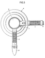
- Fig. 3 is its plan view.
- Reference numeral 1 denotes a handle
- 2 is a side handle, and the operator holds two handles 1, 2 to do the polishing work.
- Reference numeral 3 is a main body of polishing tool, in which an air motor 11 is incorporated.
- Reference numeral 4 is a pad for polishing
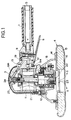
- 5 is a compressed air connection port provided at the end of the handle 1, and by opening a main valve 9 by a main lever 8, the supplied compressed air manipulates an air motor control valve 10 by an air motor control lever 7 to drive an air motor 11, thereby driving the pad 4 which is eccentrically driven by a rotary shaft 12.
- a cooling air control valve 13 By manipulating a cooling air control valve 13 by a cooling air control lever 6, the feed rate of the cooling air is controlled.
- the pad 4 is fitted to a pad base 14 which rotates and oscillates, and is composed of sponge 15 and wool buff 16.
- a pad base 14 which rotates and oscillates, and is composed of sponge 15 and wool buff 16.
- an air motor exhaust filter17 is provided at the end of the side handle 2 (Fig. 3).
- the pad base 14 is fitted to the rotary shaft 12 through a pad skirt 18.
- the compressed air introduced into the main body 3 from the compressed air connection port 5 provided at the end of the handle 1 is led into a common passage 19 in the main body by releasing the main valve 9, and is then branched into a driving source passage 19a and a cooling air passage 19b.
- the compressed air led into the driving source passage 19a side is adequately controlled by the air motor control valve 10 to rotate the air motor 11, and passes through the passage in the side handle 2, and is filtered through the air motor exhaust filter 17 to be rid of oil content or the like, and is discharged.
- the compressed air led into the cooling air passage 19b is adequately controlled by the cooling air control valve 13, penetrates obliquely in the main body 3, passes through an air passage 25 provided in a fixed shaft 24 in the upper part of the main body 3, and is injected through air vents 22, 23 through an air passage 21 in the rotary shaft 12.
- the vent hole 23 is nearly in the middle of the working surface, and the compressed air forms a flow moving from here in the outer circumferential direction (see arrow a).
- This flow of air also scatters the polishing waste chips remaining on the workpiece surface to clean the working surface.
- Fig. 5 shows an example of leading the cooling air flowing path into the air passage 21 in the rotary shaft 12 by passing through a different passage from the embodiment above after branching off from the common passage 19 in the main body 3.
- the cooling air passage 19b branching off from the common passage 19 descends the air passage 20 in the main body 3, and flows from the air passage 21a provided in the lateral direction in the rotary shaft 12 through the air passage 21 in the rotary shaft 12, and is injected through the air vents 22, 23.
- both the tool side and workpiece side are cooled.
- both the tool side and workpiece side are cooled.
- the working surface is cleaned, and therefore a favorable finished surface is obtained, while the working efficiency may be notably enhanced because it is not required to interrupt the work to cool or clean.
Landscapes
- Engineering & Computer Science (AREA)
- Mechanical Engineering (AREA)
- Grinding-Machine Dressing And Accessory Apparatuses (AREA)
- Constituent Portions Of Griding Lathes, Driving, Sensing And Control (AREA)
- Finish Polishing, Edge Sharpening, And Grinding By Specific Grinding Devices (AREA)
- Polishing Bodies And Polishing Tools (AREA)
Description
Claims (5)
- A polishing tool powered by air pressure, comprisinga driving source passage (19a) in a main body (3) for supplying compressed air for working from a single connection port (5)a cooling air passage (19b) for injecting air through an air passage (21) in a motor rotary shaft (12) in the central part of the polishing working surface,
characterized in thatthe driving source passage (19a) and the cooling air passage (19b) are both connected within the main body (3) with the single connection port (5) andan independently acting control valve (10, 13) is provided in each individual passage (19a, 19b). - The polishing tool of claim 1,
wherein a main control valve (9) is provided in a connection passage between the single connection port (5) and the connection of the driving source passage (19a) and the cooling air passage (19b). - The polishing tool of claim 1 or 2,
wherein the outlet of the air motor (11) is connected to an exhaust filter (17) at the end of a side handle (2). - The polishing tool of one of claims 1 to 3,
wherein the cooling air passage (19b) is connected with the vent hole (23) through an air passage (21) in a rotary shaft (12) driving a polishing pad (4). - The polishing tool of one of claims 1 to 3,
wherein the cooling air passage (19b) is connected with the vent hole (23) through an air passage (21a) provided in a lateral direction to a rotary shaft (12) driving a polishing pad (4) and an air passage (21) in the rotary shaft (12).
Applications Claiming Priority (2)
| Application Number | Priority Date | Filing Date | Title |
|---|---|---|---|
| JP14910194A JPH0811045A (en) | 1994-06-30 | 1994-06-30 | Abrasive tools powered by air pressure |
| JP149101/94 | 1994-06-30 |
Publications (2)
| Publication Number | Publication Date |
|---|---|
| EP0691181A1 EP0691181A1 (en) | 1996-01-10 |
| EP0691181B1 true EP0691181B1 (en) | 1998-09-16 |
Family
ID=15467724
Family Applications (1)
| Application Number | Title | Priority Date | Filing Date |
|---|---|---|---|
| EP19950109746 Expired - Lifetime EP0691181B1 (en) | 1994-06-30 | 1995-06-22 | Polishing tool powered by air pressure |
Country Status (5)
| Country | Link |
|---|---|
| EP (1) | EP0691181B1 (en) |
| JP (1) | JPH0811045A (en) |
| DE (1) | DE69504769T2 (en) |
| ES (1) | ES2124468T3 (en) |
| TW (1) | TW345521B (en) |
Cited By (6)
| Publication number | Priority date | Publication date | Assignee | Title |
|---|---|---|---|---|
| EP1688061A1 (en) | 2005-02-03 | 2006-08-09 | Monti-Werkzeuge Gmbh | Rotary tool |
| EP2147744A1 (en) | 2008-07-22 | 2010-01-27 | Peugeot Citroën Automobiles S.A. | Compressed-air polishing device equipped with cooling means |
| US7722444B2 (en) | 2005-05-13 | 2010-05-25 | Black & Decker Inc. | Angle grinder |
| DE102009013263A1 (en) * | 2009-03-14 | 2010-09-16 | Kochanski, Boris, Dipl.-Ing. | Polishing or grinding device |
| WO2011073547A1 (en) | 2009-12-16 | 2011-06-23 | Peugeot Citroën Automobiles SA | Compressed-air polishing device provided with a cooling means |
| US10818450B2 (en) | 2017-06-14 | 2020-10-27 | Black & Decker Inc. | Paddle switch |
Families Citing this family (17)
| Publication number | Priority date | Publication date | Assignee | Title |
|---|---|---|---|---|
| US6257970B1 (en) | 1997-01-23 | 2001-07-10 | Hao Chien Chao | Ergonomically friendly random orbital construction |
| US6855040B2 (en) | 1997-01-23 | 2005-02-15 | Hao Chien Chao | Ergonomically friendly orbital sander construction |
| AUPQ618800A0 (en) * | 2000-03-10 | 2000-04-06 | Bayly Design Associates Pty Ltd | Power tool |
| JP4701647B2 (en) * | 2004-07-13 | 2011-06-15 | 日産自動車株式会社 | How to repair the coating |
| KR100705310B1 (en) * | 2005-01-12 | 2007-04-10 | 최철환 | Multifunctional Chamfering Air Tool |
| KR100787822B1 (en) * | 2007-04-25 | 2007-12-21 | 인영건설 주식회사 | Air-cooled wheel blade chiller and cooling method for dry wheel saw application |
| IT1395130B1 (en) | 2009-07-31 | 2012-09-05 | Valentini | PNEUMATIC MACHINE WITH HANDLE WITH INFLATABLE SHELL. |
| DE102010006122A1 (en) | 2010-01-26 | 2011-07-28 | Kochanski, Boris, Dipl.-Ing., 46240 | Compressed air operated machine mainly for polishing or grinding a workpiece with cooling thereof, generated by unused drive power |
| US8303380B2 (en) * | 2010-01-26 | 2012-11-06 | Dynabrade, Inc. | Abrading device having a front exhaust |
| DE102011014653A1 (en) * | 2011-03-21 | 2012-09-27 | Boris Kochanski | Polishing or grinding device i.e. pressurized air power tool, for polishing or grinding coated surface i.e. motor car part, in automobile industry, has pressurized air guide device comprising work spindle rotatable in air guidance cup |
| KR101449980B1 (en) * | 2012-07-30 | 2014-10-15 | 우경섭 | Marine valve grinding rotation equipment |
| KR101497452B1 (en) * | 2013-04-26 | 2015-03-02 | 삼성중공업 주식회사 | Air Grinder and Milling Apparatus for Excluding Bead Weld |
| US20150056897A1 (en) * | 2013-08-22 | 2015-02-26 | X'pole Precision Tools Inc. | Sander providing airflow correction |
| EP2842687A1 (en) * | 2013-08-30 | 2015-03-04 | X'Pole Precision Tools, Inc. | Sander providing airflow correction |
| US9339906B2 (en) * | 2014-06-23 | 2016-05-17 | Sp Air Kabushiki Kaisha | Pneumatic beveler |
| JP6387442B1 (en) * | 2017-06-27 | 2018-09-05 | 鼎朋企業股▲ふん▼有限公司 | Polishing machine |
| JP7175531B1 (en) * | 2021-08-23 | 2022-11-21 | 株式会社信濃製作所 | chamfering machine |
Family Cites Families (7)
| Publication number | Priority date | Publication date | Assignee | Title |
|---|---|---|---|---|
| US2733562A (en) * | 1956-02-07 | Wheel spindle for grinding machines | ||
| US3871097A (en) * | 1972-07-17 | 1975-03-18 | Chris R Melde | Cooling system for a dental handpiece |
| US4091577A (en) * | 1976-11-02 | 1978-05-30 | Antonio Ortiz | Wet-sanding machine |
| ATE106300T1 (en) * | 1989-04-01 | 1994-06-15 | Messer Griesheim Gmbh | POLISHING OR GRINDING EQUIPMENT. |
| DE8904020U1 (en) * | 1989-04-01 | 1989-06-08 | Lübbering, Johannes, 33442 Herzebrock-Clarholz | Cold gas processing device |
| DE4236964A1 (en) * | 1992-11-02 | 1994-05-05 | Hilti Ag | Disc-shaped tool for angle grinders |
| EP0989584B1 (en) * | 1998-09-23 | 2004-11-24 | Advantest Corporation | Device for reducing the energy width of a particle beam and a particle beam apparatus with such a device |
-
1994
- 1994-06-30 JP JP14910194A patent/JPH0811045A/en active Pending
-
1995
- 1995-06-22 ES ES95109746T patent/ES2124468T3/en not_active Expired - Lifetime
- 1995-06-22 EP EP19950109746 patent/EP0691181B1/en not_active Expired - Lifetime
- 1995-06-22 DE DE1995604769 patent/DE69504769T2/en not_active Expired - Fee Related
- 1995-06-28 TW TW084106635A patent/TW345521B/en active
Cited By (9)
| Publication number | Priority date | Publication date | Assignee | Title |
|---|---|---|---|---|
| EP1688061A1 (en) | 2005-02-03 | 2006-08-09 | Monti-Werkzeuge Gmbh | Rotary tool |
| DE102005009854A1 (en) * | 2005-02-03 | 2006-08-17 | Monti-Werkzeuge Gmbh | rotary tool |
| US7722444B2 (en) | 2005-05-13 | 2010-05-25 | Black & Decker Inc. | Angle grinder |
| US8087977B2 (en) | 2005-05-13 | 2012-01-03 | Black & Decker Inc. | Angle grinder |
| US8087976B2 (en) | 2005-05-13 | 2012-01-03 | Black & Decker Inc. | Trigger assembly for angle grinder |
| EP2147744A1 (en) | 2008-07-22 | 2010-01-27 | Peugeot Citroën Automobiles S.A. | Compressed-air polishing device equipped with cooling means |
| DE102009013263A1 (en) * | 2009-03-14 | 2010-09-16 | Kochanski, Boris, Dipl.-Ing. | Polishing or grinding device |
| WO2011073547A1 (en) | 2009-12-16 | 2011-06-23 | Peugeot Citroën Automobiles SA | Compressed-air polishing device provided with a cooling means |
| US10818450B2 (en) | 2017-06-14 | 2020-10-27 | Black & Decker Inc. | Paddle switch |
Also Published As
| Publication number | Publication date |
|---|---|
| ES2124468T3 (en) | 1999-02-01 |
| TW345521B (en) | 1998-11-21 |
| EP0691181A1 (en) | 1996-01-10 |
| DE69504769D1 (en) | 1998-10-22 |
| JPH0811045A (en) | 1996-01-16 |
| DE69504769T2 (en) | 1999-03-18 |
Similar Documents
| Publication | Publication Date | Title |
|---|---|---|
| EP0691181A1 (en) | Polishing tool powered by air pressure | |
| DE10329828B4 (en) | Hand tool with cooling device and dust extraction | |
| US4102084A (en) | Wet sanding device | |
| US5445558A (en) | Wet sander | |
| US5582541A (en) | Abrading tool with water feed and removal system | |
| CN117817365B (en) | Turning and polishing integrated machine for numerical control machining | |
| US5597348A (en) | Water feed for sanding tool | |
| EP2073949A1 (en) | Hand machine-tool | |
| EP0549202A1 (en) | Wet-sanding tools | |
| JP2009519837A (en) | Machine Tools | |
| CN113664367A (en) | A high-precision intelligent manufacturing equipment for human-computer interaction | |
| CN112372465B (en) | Automatic grinding equipment for valve inner cavity and grinding process thereof | |
| KR20090091943A (en) | Multi-purpose disk abrader | |
| CN119347444B (en) | A CNC turning, milling and grinding composite machining machine tool | |
| JP2002283183A (en) | Eyeglass lens processing equipment | |
| JP3045258B2 (en) | Spindle head cleaning unit for machining | |
| CN207841079U (en) | Polish dust dust-extraction unit | |
| CN212601249U (en) | Cutting fluid recovery unit of grinding machine | |
| JP3033073U (en) | Water polisher | |
| JP2583801Y2 (en) | Core drill | |
| JPH0727738U (en) | Follow-up coolant nozzle device | |
| JP3969244B2 (en) | Grinding wheel-associated air layer blocking method and apparatus, and coolant supply device with a grinding wheel-associated air layer blocking device | |
| JPH0224612Y2 (en) | ||
| JPH07136918A (en) | Sand for water polishing | |
| KR102279719B1 (en) | Multi-purpose portable grinder |
Legal Events
| Date | Code | Title | Description |
|---|---|---|---|
| PUAI | Public reference made under article 153(3) epc to a published international application that has entered the european phase |
Free format text: ORIGINAL CODE: 0009012 |
|
| AK | Designated contracting states |
Kind code of ref document: A1 Designated state(s): DE ES FR GB IT PT |
|
| 17P | Request for examination filed |
Effective date: 19960322 |
|
| 17Q | First examination report despatched |
Effective date: 19970516 |
|
| GRAG | Despatch of communication of intention to grant |
Free format text: ORIGINAL CODE: EPIDOS AGRA |
|
| GRAG | Despatch of communication of intention to grant |
Free format text: ORIGINAL CODE: EPIDOS AGRA |
|
| GRAH | Despatch of communication of intention to grant a patent |
Free format text: ORIGINAL CODE: EPIDOS IGRA |
|
| GRAH | Despatch of communication of intention to grant a patent |
Free format text: ORIGINAL CODE: EPIDOS IGRA |
|
| GRAA | (expected) grant |
Free format text: ORIGINAL CODE: 0009210 |
|
| AK | Designated contracting states |
Kind code of ref document: B1 Designated state(s): DE ES FR GB IT PT |
|
| REF | Corresponds to: |
Ref document number: 69504769 Country of ref document: DE Date of ref document: 19981022 |
|
| ET | Fr: translation filed | ||
| REG | Reference to a national code |
Ref country code: ES Ref legal event code: FG2A Ref document number: 2124468 Country of ref document: ES Kind code of ref document: T3 |
|
| REG | Reference to a national code |
Ref country code: PT Ref legal event code: SC4A Free format text: AVAILABILITY OF NATIONAL TRANSLATION Effective date: 19981124 |
|
| PLBE | No opposition filed within time limit |
Free format text: ORIGINAL CODE: 0009261 |
|
| STAA | Information on the status of an ep patent application or granted ep patent |
Free format text: STATUS: NO OPPOSITION FILED WITHIN TIME LIMIT |
|
| 26N | No opposition filed | ||
| PGFP | Annual fee paid to national office [announced via postgrant information from national office to epo] |
Ref country code: DE Payment date: 20000629 Year of fee payment: 6 |
|
| PGFP | Annual fee paid to national office [announced via postgrant information from national office to epo] |
Ref country code: GB Payment date: 20000717 Year of fee payment: 6 |
|
| PGFP | Annual fee paid to national office [announced via postgrant information from national office to epo] |
Ref country code: FR Payment date: 20000718 Year of fee payment: 6 |
|
| PGFP | Annual fee paid to national office [announced via postgrant information from national office to epo] |
Ref country code: ES Payment date: 20000721 Year of fee payment: 6 |
|
| PGFP | Annual fee paid to national office [announced via postgrant information from national office to epo] |
Ref country code: PT Payment date: 20000822 Year of fee payment: 6 |
|
| PG25 | Lapsed in a contracting state [announced via postgrant information from national office to epo] |
Ref country code: GB Free format text: LAPSE BECAUSE OF NON-PAYMENT OF DUE FEES Effective date: 20010622 |
|
| PG25 | Lapsed in a contracting state [announced via postgrant information from national office to epo] |
Ref country code: ES Free format text: LAPSE BECAUSE OF NON-PAYMENT OF DUE FEES Effective date: 20010623 |
|
| PG25 | Lapsed in a contracting state [announced via postgrant information from national office to epo] |
Ref country code: PT Free format text: LAPSE BECAUSE OF NON-PAYMENT OF DUE FEES Effective date: 20011231 |
|
| GBPC | Gb: european patent ceased through non-payment of renewal fee |
Effective date: 20010622 |
|
| PG25 | Lapsed in a contracting state [announced via postgrant information from national office to epo] |
Ref country code: FR Free format text: LAPSE BECAUSE OF NON-PAYMENT OF DUE FEES Effective date: 20020228 |
|
| PG25 | Lapsed in a contracting state [announced via postgrant information from national office to epo] |
Ref country code: DE Free format text: LAPSE BECAUSE OF NON-PAYMENT OF DUE FEES Effective date: 20020403 |
|
| REG | Reference to a national code |
Ref country code: PT Ref legal event code: MM4A Free format text: LAPSE DUE TO NON-PAYMENT OF FEES Effective date: 20011231 |
|
| REG | Reference to a national code |
Ref country code: ES Ref legal event code: FD2A Effective date: 20030203 |
|
| PG25 | Lapsed in a contracting state [announced via postgrant information from national office to epo] |
Ref country code: IT Free format text: LAPSE BECAUSE OF NON-PAYMENT OF DUE FEES Effective date: 20050622 |