EP0691101A1 - Powdered and liquid detergent and additive detergent integrated dispenser for wasching machines, in particular household dish-washing machines - Google Patents
Powdered and liquid detergent and additive detergent integrated dispenser for wasching machines, in particular household dish-washing machines Download PDFInfo
- Publication number
- EP0691101A1 EP0691101A1 EP95110111A EP95110111A EP0691101A1 EP 0691101 A1 EP0691101 A1 EP 0691101A1 EP 95110111 A EP95110111 A EP 95110111A EP 95110111 A EP95110111 A EP 95110111A EP 0691101 A1 EP0691101 A1 EP 0691101A1
- Authority
- EP
- European Patent Office
- Prior art keywords
- container
- detergent
- powdered
- dispenser according
- machines
- Prior art date
- Legal status (The legal status is an assumption and is not a legal conclusion. Google has not performed a legal analysis and makes no representation as to the accuracy of the status listed.)
- Granted
Links
- 239000003599 detergent Substances 0.000 title claims abstract description 85
- 239000007788 liquid Substances 0.000 title claims abstract description 22
- 239000000654 additive Substances 0.000 title claims abstract description 21
- 230000000996 additive effect Effects 0.000 title claims abstract description 21
- 238000004851 dishwashing Methods 0.000 title claims abstract description 12
- 238000005406 washing Methods 0.000 claims abstract description 26
- 239000000463 material Substances 0.000 claims abstract description 14
- 239000002991 molded plastic Substances 0.000 claims abstract description 3
- 230000002093 peripheral effect Effects 0.000 claims description 12
- 238000003825 pressing Methods 0.000 claims description 7
- 230000004308 accommodation Effects 0.000 claims description 3
- 238000007789 sealing Methods 0.000 claims description 3
- 238000003780 insertion Methods 0.000 claims description 2
- 230000037431 insertion Effects 0.000 claims description 2
- 210000002105 tongue Anatomy 0.000 claims description 2
- 230000007246 mechanism Effects 0.000 description 3
- 238000004140 cleaning Methods 0.000 description 2
- 238000004891 communication Methods 0.000 description 2
- 238000010276 construction Methods 0.000 description 2
- 238000006073 displacement reaction Methods 0.000 description 2
- 238000012423 maintenance Methods 0.000 description 2
- 239000012780 transparent material Substances 0.000 description 2
- 230000006835 compression Effects 0.000 description 1
- 238000007906 compression Methods 0.000 description 1
- 238000001816 cooling Methods 0.000 description 1
- 238000007599 discharging Methods 0.000 description 1
- 238000001914 filtration Methods 0.000 description 1
- 239000011796 hollow space material Substances 0.000 description 1
- 238000009434 installation Methods 0.000 description 1
- 239000012858 resilient material Substances 0.000 description 1
Images


Classifications
-
- A—HUMAN NECESSITIES
- A47—FURNITURE; DOMESTIC ARTICLES OR APPLIANCES; COFFEE MILLS; SPICE MILLS; SUCTION CLEANERS IN GENERAL
- A47L—DOMESTIC WASHING OR CLEANING; SUCTION CLEANERS IN GENERAL
- A47L15/00—Washing or rinsing machines for crockery or tableware
- A47L15/42—Details
- A47L15/44—Devices for adding cleaning agents; Devices for dispensing cleaning agents, rinsing aids or deodorants
- A47L15/4409—Devices for adding cleaning agents; Devices for dispensing cleaning agents, rinsing aids or deodorants by tipping containers or opening their lids, e.g. with the help of a programmer
-
- A—HUMAN NECESSITIES
- A47—FURNITURE; DOMESTIC ARTICLES OR APPLIANCES; COFFEE MILLS; SPICE MILLS; SUCTION CLEANERS IN GENERAL
- A47L—DOMESTIC WASHING OR CLEANING; SUCTION CLEANERS IN GENERAL
- A47L15/00—Washing or rinsing machines for crockery or tableware
- A47L15/42—Details
- A47L15/4251—Details of the casing
- A47L15/4257—Details of the loading door
Definitions
- the invention refers to a powdered and liquid detergent and additive detergent integrated dispenser for washing machines, in particular household dish-washing machines, adapted to hold metered amounts of these detergent materials, such as to permit that both a plurality of washing cycles and only one washing cycle be performed, as well as such detergent materials to be delivered to the tank of these washing machines at pre-established moments of the cycle.
- the present washing machines and in particular the household dish-washing machines are substantially provided with at least a detergent dispenser, subdivided in different separate chambers for holding the detergents, particularly the powdered ones, and the liquid additive detergents like the brightness conditioner, which dispenser is generally fitted inside the machine door, and in which the respective detergent materials are introduced in the correspondent chambers, before each washing cycle, on amounts enough to perform a washing cycle, so that during the same cycle these materials are introduced in the tank with conventional mechanisms associated to the same dispenser, so as to ensure effective washings of dishes.
- a detergent dispenser subdivided in different separate chambers for holding the detergents, particularly the powdered ones, and the liquid additive detergents like the brightness conditioner, which dispenser is generally fitted inside the machine door, and in which the respective detergent materials are introduced in the correspondent chambers, before each washing cycle, on amounts enough to perform a washing cycle, so that during the same cycle these materials are introduced in the tank with conventional mechanisms associated to the same dispenser, so as to ensure effective washings of dishes.
- the detergent material dispensers of this kind require the filling thereof with the respective detergent materials to be utilized before each washing cycle of the machines and aren't designed for holding and delivering such detergent amounts as to permit to perform various washing cycles, which circumstance would simplify and facilitate considerably any setup operation of the machines before to set them at work.
- the present invention has to object to eliminate this drawback, by employing a washing detergent and additive detergent dispenser for these machines, which is made with a holding capacity of such detergent materials at such amounts as to be sufficient to perform various cycles, and which is provided for delivering automatically the doses respectively foreseen in each cycle.
- this dispenser is adapted to deliver also amounts of detergent materials for a single washing cycle and is shaped with compact dimensions, which reduce the encumbrance thereof on its position installed in the machines, and is accessible easily by the user for filling, cleaning and any maintenance operations thereof.
- This integrated dispenser which is formed by the component parts which will be described in detail in the Fig. 2, is advantageously fitted on the upper inner surface of the door 11 of the dish-washing machine 12, which door as usual is hinged frontally overturning on the same machine, and in the present case it is represented partially opened, in order to permit the access to such integrated dispenser 10 for filling it with the needed detergent materials.
- the dispenser 10 which is integrally made preferably with molded plastic material and comprises a box-like envelope 13 of parallelepiped form, or other suitable form, in which different rooms are provided on its front wall 14, for housing respectively a container 15 having a long duration storage capacity, for the introduction of powdered detergent through an upper cap 16 therein, at such amounts as to allow a plurality of washing cycles to be performed in the machine, a container 17 for liquid additive detergents like the brightness conditioner, and at least a container 18 for the powdered or liquid detergent, at such amount as to allow a single washing cycle to be performed.
- the container 15 with long duration storage capacity is advantageously shaped with an upper surface 19 and a lower one 20 having semicircular form and side surfaces 21 and 22 having rectilinear form, and is also housed in the correspondent room 23 of the box-like envelope 13, in such a way as to be hinged at the lower side of the same room, in order to be able to be displaced from an extracted position evident from the Fig. 2, for being filled with detergent through the cap 16, to a position inserted into said room, in which it enters the box-like envelope for a determinate depth thereof and its front surface flushes with the front wall 14, for the metered automatic delivery of such detergent into the machine tank on each washing cycle.
- this container 15 is provided with a peripheral outer gasket 24 (evident from the Figs. 5-7), adapted to be sealed against the correspondent peripheral edge 25 of the room 23 at the inserted position thereof into the container, for the reasons set forth below, which sealing is also made more effective thanks to the particular semicircular form of both the container upper wall 19 and lower one 20.
- the container may be made also with a different form that that described solely by way of example, by allowing always to perform the same functions thereof.
- This container 15 is provided additionally advantageously with at least a front opening 26 too, which is closed by transparent material, acting as indicator of the powdered detergent filling level into the same container, and accordingly marked with indication marks for the higher and lower detergent filling level into the container, as well as a projected handle 27, which in this case is provided on the upper side thereof, and can be grasped by the user in order to displace the same container into the above described two operative positions thereof, which handle is housed on a correspondent front recess 28 of the front wall 14 at the inserted position of said container.
- the liquid additive detergent container 17 is provided, as usual, with a removable front access cap 29 for the introduction of the liquid additive detergents therein, at least an indicator 30 for its filling level with such liquid additive detergents, made of adequate transparent material, a hole 31 for discharging the liquid additive detergents in the tank, which may be open and closed by means of per se known control means, not shown, while the container 18 is provided with an access lid 32 overturning as evident in the Figure, and movable by the machine timer from the container closed position, at the filled condition with detergents thereof, to this open position for delivering a single dose of detergent, against the action of a torsion spring 33 associated with said lid.
- the present integrated dispenser 10 also comprises a powdered detergent automatic distributing and metering system, marked with the reference numeral 34, which communicates with the inside of container 15 with long duration storage capacity, and adapted to transer automatically the detergent form the same container toward the tank, which system in the present case is arranged below the container 15 and is made and operates in a manner identical to those described in the patent application for invention n. BL93A000028, filed on 10.11.1993 by the same Applicant, to which reference is therefore made for a better comprehension of the construction and operation of the same system.
- a peripheral recess 35 is provided around the distributing and metering system 34 in the front wall 14 of the box-like envelope 13, in order to collect and discharge adequately into the tank any condensate and dripping from the inside of the same container.
- a rotor 36 and a pneumatic actuator 37 are housed therein, which are adapted respectively to generate compressed air for the detergent distribution as well as to act on the above cited distributing and metering system 34, in order to operate this latter with the means and in the manner described with particular reference to the above mentioned preceding patent application, so as to distribute and introduce through it metered amounts of powdered detergent from the container 15 toward the machine tank, by means of control of the timer during each washing cycle.
- a first and a second electromagnet 38 and 39 or the like are also housed on the back side of the container 15, and connected in operation in the electric circuit of the machine and controlled by the timer thereof, of which the first electromagnet 38 is arranged adjacent the upper edge of the container 15, in such a way that its movable vertical core 40 interacts with a short horizontal arm 41 of a lever 42 pivoted on a bracket 43, fixed at the back and upper side of the container 15, which lever is provided with a vertical arm 44 joined to such horizontal arm and another horizontal extended arm 45, joined orthogonally to said vertical arm 44 and having its shaped end 46 entering a correspondent recess 47 provided on the upper side of the container 15.
- the lower free end 48 of the vertical arm 44 of the lever 42 is housed on the free end of a rectilinear arm 49 of another lever 50 situated below it, which is pivoted at its other end on a stud 51 fixed below the first electromagnet 38 and connected to the overturning lid 32 of the container 18 for the single dose of powdered or liquid detergent, in such a way that such lever 50 can be rotated limitedly around this fulcrum point, against the action of a torsion spring (not shown) wound around the stud 51 and urging the same lever toward its rest position of the Fig. 3, by causing at the same time the lid to be displaced on different operative positions thereof, which will be described in detail in Figs. 8-13.
- the first electromagnet 38 is able to displace with its movable core 40 both the levers 42 and 50 simultaneously from the one to the other one of their two operative positions, respectively from the first rest position thereof, illustrated by the Fig. 3, in which the lever 42 has its shaped end 46 engaging the recess 47, thereby keeping the container 15 into its engaged condition in which the powdered detergent contained therein may be distributed by a timed controlled operation into the tank, in the manner hereinafter described, while in turn the lever 50 isn't pushed downward by the overhanging lever 42 and therefore keeps the overturning lid 32 at a closed condition thereof, engaging the container 18, thereby preventing it from being opened, to the operation position thereof, not evident, in which the lever 42 is rotated around its fulcrum point 43, thereby disengaging its shaped end 46 from the recess 47 and therefore permitting the container 15 to be opened and filled with the powdered detergent in the manner hereinafter described, while in turn the lever 50 is pushed downward by the consequent lowering of the lower free
- the second electromagnet 39 is arranged at an inclined position thereof and connected to the control means for the liquid additive detergent container 17, which are constituted preferably by a conventional valve (not shown), in such a way that to actuate the same at an opened and closed position thereof for determining or preventing the distribution of such liquid additive detergents into the tank.
- a further lever 52 is housed on the back side of the container 15, at a position below the container 15 and co-operating therewith, which lever is interconnected by means of a flexible cable 53 with the lock 54 of the door 11 of the dish-washing machine, and is pivoted rotatable thereon in such a way as to be actuated by the container 15 in two different operative positions thereof, respectively from a first position in which it pulls the flexible cable 53 downward, in the direction of the arrow B of the Fig.
- the container 15 of the present integrated dispenser in three different operative conditions thereof, in which it is noted that such container is substantially made in a manner identical to that described in the patent applications for invention n. UD93A000022 and n. UD93A000023, filed on 15.2.1993 in the name of Russi Luciano and transferred on 24.12.1993 to the name of the Applicant, and to this aim it includes an additional container 151 inside it having dimensions slightly lower, which defines a hollow space 56 between it and the surrounding walls of the container 15, for circulating a flow of cooling air generated by the rotor 36 or by natural convection, and adapted to maintain the detergent within the pre-established temperature boundary which are compatible for the use thereof.
- Such container 151 is additionally provided with adequate means for locking it into its container 15, which means aren't shown and described in the above mentioned patent applications for invention n.
- UD93A000022 and UD93A000023 and also at least an inner valve member 57 of per se known kind, acting on the lower drainage hole 58 thereof and operable through the shaped end 46 of the lever 42, which can be coupled thereto, in a manner to close or open such hole, in order to prevent or permit the detergent distribution depending on the displacement of the lever 42 into different positions thereof, as well as a filtering element 59.
- the container 15 at the closed position thereof, in which condition the additional container 151 is arranged for distributing the detergent into the tank, through the automatic distributing and metering system 34 which in this case communicates with both the drainage hole 58 of the container 151 and the tank.
- the automatic distributing and metering system 34 is operated on the opened position thereof, in which the container 151 is put into communication with the tank through the flexible conduit 60 made of resilient material, which is affected by a separated pressing member 61 adapted to be pressed or not pressed against said flexible conduit 60 (the flexible conduit and pressing member are pertaining to such distributing and metering system, for the construction and operation of which reference is made therefore to the preceding patent application for invention n. BL93A000028 of the Applicant).
- the pressing member 61 is made rotatable with a limited angle of rotation, and maintained at this rest position by a suitable compression spring 62, as well as operated by a shaft 63 (evident in the Fig. 3) orthogonal to the flexible conduit 60 and actuated in rotation by the pneumatic actuator 37 under the control operation of the machine timer, in the present example such pressing member being not compressed against the flexible conduit 60.
- the detergent isn't distributed into the tank, since the drainage hole 58 of the container 151 is closed by the valve member 57 and such distribution occurs as soon as said valve means is operated into its opened position, thereby by releasing the drainage hole 58 and permitting the detergent to pass through the flexible conduit 60.
- the pressing member 61 has been actuated by the pneumatic actuator 37 into its operative position, compressed against the flexible condit 60, in which also the spring 62 is compressed, with consequent squeezing of said flexible conduit and interruption of the connection between the container 151 and the tank, in which condition the detergent distribution into the same tank is prevented.
- This lid in particular, is provided at its inner surface with a hollow 64 and a lower projected hook 65, turned toward the inside of the container 18 and adapted to co-operate both with a correspondent counter-hook 66, projected from a bent arm 67 fixed to the stud 51 acting as a fulcrum of the lever 50 and operable in rotation by such lever, which in turn is operated by as already described by the first electromagnet 38, in such a way that such counter-hook 66 may be actuated into three different positions thereof corresponding to such operative positions of the overturning lid.
- This component part is substantially formed by a thin peripheral frame 68 having the same shape and dimensions slightly larger than the box-like envelope 13 of said integrated dispenser 10, for the accommodation around the entire peripheral outline of said box-like envelope thereof, said frame being provided with two half-portions 69 and 70 identical and symmetrical to each other, having a plurality of insertion tongues 71 which can be engaged around said box-like envelope, whose ends are provided with respective folded edges 72, 73 and 74, 75 turned toward each other and matching to each other, as well as adapted to be joined reciprocally by means of screws 76 or the like after that said half-portions have been fitted around the box-like envelope 13, at the condition in which such peripheral frame 68 holds in its seat also the peripheral sealing gasket 24 of the container 15 (see Figs. 15 and 16).
- the container 15 is housed almost at the same preceding position thereof, however in this case it has different shape (square) with dimensions slightly smaller and its handle 27 is projected laterally at the left-hand side instead of upwardly, and is hinged laterally in its accommodation space, while in turn the liquid additive detergent 17 is arranged near the upper edge of the box-like envelope 13, laterally at the left-hand side of the container 15, and at the position below it there are arranged aligned vertically both the corresponding indicator 30 and the discharge hole 31, and finally the distributing and metering system 34 is arranged below the container 18 and associated lid 32, which are held at the same preceding position thereof.
- the container 15 is practically identical to that of the Figs. 19-21 and with respect thereto it is displaced at the left-hand side, so as its handle 27 be slightly projected beyond the left-hand side peripheral edge of the same container, while in turn the liquid additive detergent container 17 is arranged between the container 15 and the container 18 with relative lid 32, which are held together with the distributing and metering system 34 at the same position of the preceding figures 19-21, and at a position below the container 17 there are arranged aligned vertically said indicator 30 and discharge hole 31.
Landscapes
- Washing And Drying Of Tableware (AREA)
- Detergent Compositions (AREA)
- Detail Structures Of Washing Machines And Dryers (AREA)
Abstract
Description
- The invention refers to a powdered and liquid detergent and additive detergent integrated dispenser for washing machines, in particular household dish-washing machines, adapted to hold metered amounts of these detergent materials, such as to permit that both a plurality of washing cycles and only one washing cycle be performed, as well as such detergent materials to be delivered to the tank of these washing machines at pre-established moments of the cycle.
- As it is known, the present washing machines and in particular the household dish-washing machines are substantially provided with at least a detergent dispenser, subdivided in different separate chambers for holding the detergents, particularly the powdered ones, and the liquid additive detergents like the brightness conditioner, which dispenser is generally fitted inside the machine door, and in which the respective detergent materials are introduced in the correspondent chambers, before each washing cycle, on amounts enough to perform a washing cycle, so that during the same cycle these materials are introduced in the tank with conventional mechanisms associated to the same dispenser, so as to ensure effective washings of dishes.
- However, the detergent material dispensers of this kind, require the filling thereof with the respective detergent materials to be utilized before each washing cycle of the machines and aren't designed for holding and delivering such detergent amounts as to permit to perform various washing cycles, which circumstance would simplify and facilitate considerably any setup operation of the machines before to set them at work.
- The present invention has to object to eliminate this drawback, by employing a washing detergent and additive detergent dispenser for these machines, which is made with a holding capacity of such detergent materials at such amounts as to be sufficient to perform various cycles, and which is provided for delivering automatically the doses respectively foreseen in each cycle.
- Moreover, this dispenser is adapted to deliver also amounts of detergent materials for a single washing cycle and is shaped with compact dimensions, which reduce the encumbrance thereof on its position installed in the machines, and is accessible easily by the user for filling, cleaning and any maintenance operations thereof.
- This detergent material integrated dispenser is made with the features substantially described with particular reference to the enclosed patent claims.
- The invention will be disclosed better by the following description, given solely by way of not-limiting example and with reference to the accompanying drawings, wherein :
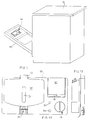
- Fig. 1 shows a perspective view of the present integrated dispenser fitted on a dish-washing machine ;
- Fig. 2 shows a perspective front and enlarged view of the present dispenser ;
- Fig. 3 shows the back side of the dispenser of Figs. 1 and 2, fitted on a dish-washing machine ;
- Fig. 4 shows a side view of the dispenser of Fig. 3 ;
- Figs. 5 and 6 show a partially cut side view of the present dispenser, displaced into two different operative positions thereof and with the closed lid ;
- Fig. 7 shows a side view of the dispenser of Figs. 5 and 6, which is partially cut at an other position thereof, and with the opened lid ;
- Figs. 8 and 9 show respective cut front and side views of a constructive item of the dispenser in accordance with the invention, displaced into a first operative position thereof;
- Figs. 10 and 11 show the item of Figs. 8 and 9, displaced into a second operative position thereof ;
- Figs. 12 and 13 show the item of Figs. 8 and 9 displaced into a third operative position thereof ;
- Fig. 14 shows a front view of a further constructive item of the present dispenser ;
- Fig. 15 shows a side view of the detail of the installation of the present dispenser on a dish-washing machine ;
- Fig. 16 shows the detail of Fig. 15 in an enlarged view ;
- Figs. 17 and 18 show a front and side view of the dispenser in accordance to the invention, in an embodiment thereof ;
- Figs. 19, 20 and 21 show respectively a front, a side and a plan view of the present dispenser, in a second embodiment thereof ;
- Fig. 22 shows a front view of another embodiment of the present dispenser.
- In the Figures referred to, it is schematically represented an integrated
dispenser 10 for powdered and liquid detergents and additive detergents for washing machines, in particular household dish-washing machines, adapted to hold such detergent materials and to deliver them into the tank of these machines at determined moments of each selected washing cycle. This integrated dispenser, which is formed by the component parts which will be described in detail in the Fig. 2, is advantageously fitted on the upper inner surface of thedoor 11 of the dish-washing machine 12, which door as usual is hinged frontally overturning on the same machine, and in the present case it is represented partially opened, in order to permit the access to such integrateddispenser 10 for filling it with the needed detergent materials. - In the Fig. 2 it is now represented the
dispenser 10, which is integrally made preferably with molded plastic material and comprises a box-like envelope 13 of parallelepiped form, or other suitable form, in which different rooms are provided on itsfront wall 14, for housing respectively acontainer 15 having a long duration storage capacity, for the introduction of powdered detergent through anupper cap 16 therein, at such amounts as to allow a plurality of washing cycles to be performed in the machine, acontainer 17 for liquid additive detergents like the brightness conditioner, and at least acontainer 18 for the powdered or liquid detergent, at such amount as to allow a single washing cycle to be performed. - In particular, the
container 15 with long duration storage capacity is advantageously shaped with anupper surface 19 and a lower one 20 having semicircular form andside surfaces correspondent room 23 of the box-like envelope 13, in such a way as to be hinged at the lower side of the same room, in order to be able to be displaced from an extracted position evident from the Fig. 2, for being filled with detergent through thecap 16, to a position inserted into said room, in which it enters the box-like envelope for a determinate depth thereof and its front surface flushes with thefront wall 14, for the metered automatic delivery of such detergent into the machine tank on each washing cycle. - Besides, this
container 15 is provided with a peripheral outer gasket 24 (evident from the Figs. 5-7), adapted to be sealed against the correspondentperipheral edge 25 of theroom 23 at the inserted position thereof into the container, for the reasons set forth below, which sealing is also made more effective thanks to the particular semicircular form of both the containerupper wall 19 and lower one 20. - Of course, the container may be made also with a different form that that described solely by way of example, by allowing always to perform the same functions thereof.
- This
container 15 is provided additionally advantageously with at least a front opening 26 too, which is closed by transparent material, acting as indicator of the powdered detergent filling level into the same container, and accordingly marked with indication marks for the higher and lower detergent filling level into the container, as well as aprojected handle 27, which in this case is provided on the upper side thereof, and can be grasped by the user in order to displace the same container into the above described two operative positions thereof, which handle is housed on a correspondent front recess 28 of thefront wall 14 at the inserted position of said container. - In turn, the liquid
additive detergent container 17 is provided, as usual, with a removablefront access cap 29 for the introduction of the liquid additive detergents therein, at least anindicator 30 for its filling level with such liquid additive detergents, made of adequate transparent material, ahole 31 for discharging the liquid additive detergents in the tank, which may be open and closed by means of per se known control means, not shown, while thecontainer 18 is provided with anaccess lid 32 overturning as evident in the Figure, and movable by the machine timer from the container closed position, at the filled condition with detergents thereof, to this open position for delivering a single dose of detergent, against the action of atorsion spring 33 associated with said lid. - The Figs. 8-13 will show better this lid.
- Finally, the present integrated
dispenser 10 also comprises a powdered detergent automatic distributing and metering system, marked with thereference numeral 34, which communicates with the inside ofcontainer 15 with long duration storage capacity, and adapted to transer automatically the detergent form the same container toward the tank, which system in the present case is arranged below thecontainer 15 and is made and operates in a manner identical to those described in the patent application for invention n. BL93A000028, filed on 10.11.1993 by the same Applicant, to which reference is therefore made for a better comprehension of the construction and operation of the same system. Advantageously, aperipheral recess 35 is provided around the distributing andmetering system 34 in thefront wall 14 of the box-like envelope 13, in order to collect and discharge adequately into the tank any condensate and dripping from the inside of the same container. - By examining now the Fig. 3, in which the back side of the
container 15 with long duration storage capacity is shown, it is noted that arotor 36 and apneumatic actuator 37 are housed therein, which are adapted respectively to generate compressed air for the detergent distribution as well as to act on the above cited distributing andmetering system 34, in order to operate this latter with the means and in the manner described with particular reference to the above mentioned preceding patent application, so as to distribute and introduce through it metered amounts of powdered detergent from thecontainer 15 toward the machine tank, by means of control of the timer during each washing cycle. - Moreover, a first and a
second electromagnet container 15, and connected in operation in the electric circuit of the machine and controlled by the timer thereof, of which thefirst electromagnet 38 is arranged adjacent the upper edge of thecontainer 15, in such a way that its movable vertical core 40 interacts with a shorthorizontal arm 41 of alever 42 pivoted on abracket 43, fixed at the back and upper side of thecontainer 15, which lever is provided with a vertical arm 44 joined to such horizontal arm and another horizontal extendedarm 45, joined orthogonally to said vertical arm 44 and having its shapedend 46 entering acorrespondent recess 47 provided on the upper side of thecontainer 15. - In turn, the lower
free end 48 of the vertical arm 44 of thelever 42 is housed on the free end of arectilinear arm 49 of another lever 50 situated below it, which is pivoted at its other end on a stud 51 fixed below thefirst electromagnet 38 and connected to the overturninglid 32 of thecontainer 18 for the single dose of powdered or liquid detergent, in such a way that such lever 50 can be rotated limitedly around this fulcrum point, against the action of a torsion spring (not shown) wound around the stud 51 and urging the same lever toward its rest position of the Fig. 3, by causing at the same time the lid to be displaced on different operative positions thereof, which will be described in detail in Figs. 8-13. In this manner, thefirst electromagnet 38 is able to displace with its movable core 40 both thelevers 42 and 50 simultaneously from the one to the other one of their two operative positions, respectively from the first rest position thereof, illustrated by the Fig. 3, in which thelever 42 has its shapedend 46 engaging therecess 47, thereby keeping thecontainer 15 into its engaged condition in which the powdered detergent contained therein may be distributed by a timed controlled operation into the tank, in the manner hereinafter described, while in turn the lever 50 isn't pushed downward by the overhanginglever 42 and therefore keeps the overturninglid 32 at a closed condition thereof, engaging thecontainer 18, thereby preventing it from being opened, to the operation position thereof, not evident, in which thelever 42 is rotated around itsfulcrum point 43, thereby disengaging its shapedend 46 from therecess 47 and therefore permitting thecontainer 15 to be opened and filled with the powdered detergent in the manner hereinafter described, while in turn the lever 50 is pushed downward by the consequent lowering of the lowerfree end 48 of the vertical arm 44 of thelever 42, so that such lever 50 by rotating in the direction indicated by the arrow A causes the displacement of the overturninglid 32 of thecontainer 18 in the released position thereof, in which it is opened and therefore permits the detergent contained therein to be distributed in the tank. Besides, thesecond electromagnet 39 is arranged at an inclined position thereof and connected to the control means for the liquidadditive detergent container 17, which are constituted preferably by a conventional valve (not shown), in such a way that to actuate the same at an opened and closed position thereof for determining or preventing the distribution of such liquid additive detergents into the tank. Finally, afurther lever 52 is housed on the back side of thecontainer 15, at a position below thecontainer 15 and co-operating therewith, which lever is interconnected by means of aflexible cable 53 with the lock 54 of thedoor 11 of the dish-washing machine, and is pivoted rotatable thereon in such a way as to be actuated by thecontainer 15 in two different operative positions thereof, respectively from a first position in which it pulls theflexible cable 53 downward, in the direction of the arrow B of the Fig. 4, when thecontainer 15 is housed on its seat and engaged by thelever 42, in which condition acontrol mechanism 55 of conventional kind provided on the free end ofsuch cable 53 does not affect said lock 54 and therefore any opening and closing operation of said door by means of said lock is permitted, to a second operative position thereof in which thelever 52 displaces the cable upward, in the direction of the arrow C of Fig. 4, when thecontainer 15 is released by thelever 42 and therefore moved to its opened position, in which condition thecontrol mechanism 55 of thecable 53 affects the lock 54, thereby preventing thedoor 11 from being closed. - By referring now to the Figs. 5, 6 and 7, shown therein is the
container 15 of the present integrated dispenser in three different operative conditions thereof, in which it is noted that such container is substantially made in a manner identical to that described in the patent applications for invention n. UD93A000022 and n. UD93A000023, filed on 15.2.1993 in the name of Russi Luciano and transferred on 24.12.1993 to the name of the Applicant, and to this aim it includes anadditional container 151 inside it having dimensions slightly lower, which defines ahollow space 56 between it and the surrounding walls of thecontainer 15, for circulating a flow of cooling air generated by therotor 36 or by natural convection, and adapted to maintain the detergent within the pre-established temperature boundary which are compatible for the use thereof.Such container 151 is additionally provided with adequate means for locking it into itscontainer 15, which means aren't shown and described in the above mentioned patent applications for invention n. - UD93A000022 and UD93A000023, and also at least an
inner valve member 57 of per se known kind, acting on thelower drainage hole 58 thereof and operable through theshaped end 46 of thelever 42, which can be coupled thereto, in a manner to close or open such hole, in order to prevent or permit the detergent distribution depending on the displacement of thelever 42 into different positions thereof, as well as afiltering element 59. In the Figs. 5 and 6 is shown thecontainer 15 at the closed position thereof, in which condition theadditional container 151 is arranged for distributing the detergent into the tank, through the automatic distributing andmetering system 34 which in this case communicates with both thedrainage hole 58 of thecontainer 151 and the tank. - In Fig. 5, in particular, it is noted that the automatic distributing and
metering system 34 is operated on the opened position thereof, in which thecontainer 151 is put into communication with the tank through theflexible conduit 60 made of resilient material, which is affected by a separated pressingmember 61 adapted to be pressed or not pressed against said flexible conduit 60 (the flexible conduit and pressing member are pertaining to such distributing and metering system, for the construction and operation of which reference is made therefore to the preceding patent application for invention n. BL93A000028 of the Applicant). - In this case, the
pressing member 61 is made rotatable with a limited angle of rotation, and maintained at this rest position by asuitable compression spring 62, as well as operated by a shaft 63 (evident in the Fig. 3) orthogonal to theflexible conduit 60 and actuated in rotation by thepneumatic actuator 37 under the control operation of the machine timer, in the present example such pressing member being not compressed against theflexible conduit 60. - Under these circumstances, however, the detergent isn't distributed into the tank, since the
drainage hole 58 of thecontainer 151 is closed by thevalve member 57 and such distribution occurs as soon as said valve means is operated into its opened position, thereby by releasing thedrainage hole 58 and permitting the detergent to pass through theflexible conduit 60. On the contrary, in the Fig. 6 it is noted that thepressing member 61 has been actuated by thepneumatic actuator 37 into its operative position, compressed against theflexible condit 60, in which also thespring 62 is compressed, with consequent squeezing of said flexible conduit and interruption of the connection between thecontainer 151 and the tank, in which condition the detergent distribution into the same tank is prevented. - Finally, in the Fig. 7 it is noted that in this case the
container 15 is displaced into the opened position thereof, being extracted forward and rotated around its lower hinged position, in which condition the shapedend 46 of thelever 42 is disengaged from therecess 47 of the same container, with consequent access to theadditional container 151 for filling it with the powdered detergent or for any possible cleaning or maintenance operation thereof, in which circumstance the communication between thedrainage hole 58 of said additional container and theflexible conduit 60 is interrupted. By examining now the Figs. 8-13, it is shown schematically theoverturning lid 32 for the access to the detergentsingle dose container 18, which is represented into three different operative positions thereof. - This lid, in particular, is provided at its inner surface with a hollow 64 and a lower projected
hook 65, turned toward the inside of thecontainer 18 and adapted to co-operate both with acorrespondent counter-hook 66, projected from abent arm 67 fixed to the stud 51 acting as a fulcrum of the lever 50 and operable in rotation by such lever, which in turn is operated by as already described by thefirst electromagnet 38, in such a way thatsuch counter-hook 66 may be actuated into three different positions thereof corresponding to such operative positions of the overturning lid. - In the Figs. 8 and 9, in particular, it is noted that the
lid 32 is closed in front of thecontainer 18, in which condition thecounter-hook 66 has been displaced upward by the rotation of the lever 50, so as to engage the hollow 64 only and to be disengaged from thehook 65. - Then, at this operative position of the
lid 32, it is kept engaged and permits thecontainer 18 to be filled with detergent, and may be disengaged manually therefrom for any possible introduction of additional detergent therein. - In the Figs. 10 and 11 it is noted that the
counter-hook 66 has been displaced by the rotation of the lever 50 at a position intermediate between the hollow 64 and thehook 65, in which it is disengaged from both and therefore permits thelid 32 to be opened and the dose of detergent to be distributed from thecontainer 18 toward the machine tank. - Finally, in the Figs. 12 and 13 it is noted that the
counter-hook 66 has been displaced downward by the rotation of the lever 50, so as to engage thehook 65 only and to be disengaged from the hollow 64. - Then, at this operative position of the
lid 32, it remains engaged permanently and cannot be opened automatically therefrom, thereby excluding the possibility to add still detergent in thecontainer 18 during the carrying out of each washing cycle, with subsequent lid unlocking which is made possible by displacing thecounter-hook 66 again into its other operative positions in the same manners as described above. In the Figs. 14-16 it is now illustrated another constructive component part of the present integrated dispenser, which permits a simple and quick assembling and disassembling thereof with respect to the dish-washing machine. This component part is substantially formed by a thinperipheral frame 68 having the same shape and dimensions slightly larger than the box-like envelope 13 of said integrateddispenser 10, for the accommodation around the entire peripheral outline of said box-like envelope thereof, said frame being provided with two half-portions insertion tongues 71 which can be engaged around said box-like envelope, whose ends are provided with respective foldededges screws 76 or the like after that said half-portions have been fitted around the box-like envelope 13, at the condition in which suchperipheral frame 68 holds in its seat also theperipheral sealing gasket 24 of the container 15 (see Figs. 15 and 16). - By examining now the remaining Figures 17-22, shown therein are different possible embodiments of the present integrated dispenser, obtained by modifying adequately the reciprocal arrangement of the different component parts of the same dispenser. In the Figs. 17 and 18 it is noted that the arrangement of the different component parts is practically the same of the Fig. 2, except that in this case the
container 15 is shaped in a reversed mode and both theindicator 30 and thedischarge hole 31 of the liquidadditive detergent container 17 are aligned with each other in a vertical direction instead of horizontal one, as from the Fig. 2. In the Figs. 19, 20 and 21 it is noted that thecontainer 15 is housed almost at the same preceding position thereof, however in this case it has different shape (square) with dimensions slightly smaller and itshandle 27 is projected laterally at the left-hand side instead of upwardly, and is hinged laterally in its accommodation space, while in turn theliquid additive detergent 17 is arranged near the upper edge of the box-like envelope 13, laterally at the left-hand side of thecontainer 15, and at the position below it there are arranged aligned vertically both thecorresponding indicator 30 and thedischarge hole 31, and finally the distributing andmetering system 34 is arranged below thecontainer 18 and associatedlid 32, which are held at the same preceding position thereof. - Finally, in the Fig. 22 it is noted that the
container 15 is practically identical to that of the Figs. 19-21 and with respect thereto it is displaced at the left-hand side, so as itshandle 27 be slightly projected beyond the left-hand side peripheral edge of the same container, while in turn the liquidadditive detergent container 17 is arranged between thecontainer 15 and thecontainer 18 withrelative lid 32, which are held together with the distributing andmetering system 34 at the same position of the preceding figures 19-21, and at a position below thecontainer 17 there are arranged aligned vertically saidindicator 30 anddischarge hole 31. Of course, it is also possible to arrange these component parts in different manners and combinations with respect to those described by way of example only, as well as it is also possible to operate these component parts with different criteria with respect to those previously described, provided that it is always obtained an identical operation of the present integrated dispenser, thereby without departing from the protection field of the invention.
Claims (11)
- Powdered and liquid detergent and additive detergent integrated dispenser for washing machines, in particular household dish-washing machines, which may be fitted preferably on the front closing door of these machines, adapted to contain such detergents and additive detergents and to distribute them into the tank of these machines during each washing cycle, with the aid of pneumatic generator means and pneumatic actuator means of per se known type, associated to an automatic distributing and metering system adapted to permit or prevent said powdered detergent to pass therethrough, as described in the patent application for invention n. BL93A000028, filed on 10.11.1993 by the same Applicant, characterized in that it includes, embodied into at least a box-like envelope (13) made preferably of molded plastic material or the like, at least a first container (15) having a long duration storage capacity containing powdered detergent, at such amounts as to allow a plurality of washing cycles to be performed, at least a second container (17) for liquid additive detergents like the brightness conditioner and the like, and at least a third container (18) for the powdered or liquid detergent, at such amount as to allow a single washing cycle to be performed, as well as said pneumatic generator means (36) and said distributing and metering system (34) which communicate with the inside of said first container (15), and finally said pneumatic actuator means (37) adapted to control said distributing and metering system (34) in a manner to permit or prevent the passage of said powdered detergents, said box-like envelope (13) being embodying also first and second control means (38, 39) respectively adapted to displace contemporaneously said first and third container (15, 18) form a first position of filling with detergents thereof, to a second position of detergent distribution therefrom, and vice versa, as well as to displace said second container (17) from a detergent filling position to a detergent distribution position, and vice versa.
- Dispenser according to claim 1, characterized in that said first container (15) is housed hinged on a correspondent front room (23) of said box-like envelope (13) and is provided with at least a peripheral sealing gasket (24) or the like, adapted to be tightly sealed against the correspondent peripheral edges of said room (23) when said first container (15) is displaced into its filling position, as well as at least a projected handle (27) which can be grasped by the user, and valve means (57) operable at the opened or closed position thereof, for permitting or preventing the detergent distribution.
- Dispenser according to claim 2, characterized in that said first container (15) is provided with lever means (42) pivoted thereto and removaly couplable to said valve means (57), an end of which can engage and disengage the same container, and the other end of which interacts with said first control means (38) in such a way that to be able to be displaced by this latter from a position in which said lever means (42) engage said first container (15), at the condition in which it is arranged for the detergent distribution through said valve means (57), to a position in which said lever means (42) are released from said first container (15) at the filling condition with detergent thereof.
- Dispenser according to claim 1, characterized in that said second container (17) is provided with a removable front access cap (29) and inner valve means operable by said second control means (39) from a closed to an opened position thereof, and vice versa, in order to prevent or permit the distribution in the tank of the detergent contained therein.
- Dispenser according to claim 1, characterized in that said third container (18) is provided with an overturning access lid (32), displaceable by means of additional lever means (50, 51, 67) operable by said first control means (38) into a first, a second and a third operative position thereof, in which said lid (32) is respectively engaged, with the possibility of manual releasing thereof, or disengaged with respect to said third container (18), as well as engages this latter without the possibility of automatic releasing thereof.
- Dispenser according to claim 5, characterized in that said lid (32) is provided at its inner surface with a hollow (64) and a lower projected hook (65), turned toward the inside of said third container (18) and adapted to co-operate both with a correspondent counter-hook (66) fixed to said additional lever means (50, 51, 67), in a way that said counter-hook (66) can engage either said hollow (64) or said hook (65) at the respective first and third operative position of said lid (32), and disengages said hollow (64) and said hook (65) at the second operative position of said lid (32).
- Dispenser according to the preceding claims, characterized in that it comprises additional lever means (52) associated to said first container (15) and interconnected by means of a flexible cable (53) or the like with the lock (54) of said machine door (11), said lever means (52) being operable by said first container (15) from a first operative position thereof, in which said cable (53) does not affect said lock (54) therefore allowing the opening and closing of said door (11), when said first container (15) is housed into its seat and engaged by said lever means (42), to a second operative position thereof in which said cable (53) affects said lock (54), thereby preventing said door (11) from being closed when said first container (15) is released by said lever means (42).
- Dispenser according to the preceding claims, characterized in that said distributing and metering system (34) is associated with pressing means (61) rotatably fixed to a shaft (63), operable by said pneumatic actuator (37), said pressing means (61) being operable by said pneumatic actuator (37) from the one to the other one of two operative positions thereof, in which they act against said distributing and metering system (34) in a way that to permit or prevent the passage of the detergent toward the tank.
- Dispenser according to the preceding claims, characterized in that said first and second control means (38, 39) are formed by a respective electromagnet or the like.
- Dispenser according to the preceding claims, characterized in that it is enclosed by a thin peripheral frame (68) for the assembling and disassembling with respect to the machine thereof, said frame (68) having preferably the same shape and dimensions slightly larger than said box-like envelope (13), for the accommodation around the entire peripheral outline of said box-like envelope (13), and being provided with two half-portions (69, 70) identical and symmetrical to each other provided with a plurality of insertion tongues (71), whose ends have respective folded edges (72, 73; 74, 75) turned toward each other and matching to each other, as well as which can be joined reciprocally by means of screws (76) or the like.
- Dispenser according to the preceding claims, characterized in that said first, second and third container (15, 17, 18) and said distributing and metering system (34) may be fitted with different arrangements thereof on said box-like envelope (13).
Applications Claiming Priority (2)
| Application Number | Priority Date | Filing Date | Title |
|---|---|---|---|
| ITBL940006 IT230721Y1 (en) | 1994-07-05 | 1994-07-05 | INTEGRATED DISPENSER OF DETERGENTS AND ADDITIVES IN POWDER AND LIQUIDS FOR WASHING MACHINES, IN PARTICULAR DOMESTIC DISHWASHER MACHINES |
| ITBL940006U | 1994-07-05 |
Publications (2)
| Publication Number | Publication Date |
|---|---|
| EP0691101A1 true EP0691101A1 (en) | 1996-01-10 |
| EP0691101B1 EP0691101B1 (en) | 2000-03-22 |
Family
ID=11336881
Family Applications (1)
| Application Number | Title | Priority Date | Filing Date |
|---|---|---|---|
| EP19950110111 Expired - Lifetime EP0691101B1 (en) | 1994-07-05 | 1995-06-29 | Powdered and liquid detergent and additive detergent integrated dispenser for wasching machines, in particular household dish-washing machines |
Country Status (3)
| Country | Link |
|---|---|
| EP (1) | EP0691101B1 (en) |
| DE (1) | DE69515744D1 (en) |
| IT (1) | IT230721Y1 (en) |
Cited By (21)
| Publication number | Priority date | Publication date | Assignee | Title |
|---|---|---|---|---|
| WO2001026533A1 (en) * | 1999-10-13 | 2001-04-19 | Eltek S.P.A. | Washing agents dispenser for a domestic washing machine, namely a dishwasher |
| WO2003022121A1 (en) * | 2001-09-11 | 2003-03-20 | Arçelik A.S. | A household appliance |
| EP1557122A3 (en) * | 2004-01-21 | 2006-08-02 | Electrolux Home Products Corporation N.V. | Electric cleaning device having a chamber for cleaning material |
| WO2007074007A1 (en) * | 2005-12-23 | 2007-07-05 | BSH Bosch und Siemens Hausgeräte GmbH | Dishwasher with an improved arrangement of the feed device in the door |
| US7754026B2 (en) | 2007-11-08 | 2010-07-13 | Whirlpool Corporation | Dishwasher with sonic cleaner |
| US7931032B1 (en) * | 2006-05-19 | 2011-04-26 | Knight, Llc | Bulk dispensing of chemicals into a residential dishwasher |
| EP2363057A1 (en) * | 2010-03-03 | 2011-09-07 | BSH Bosch und Siemens Hausgeräte GmbH | Domestic appliance, in particular cooking device and supply container |
| DE19924897B4 (en) * | 1999-06-01 | 2012-01-26 | Aweco Appliance Systems Gmbh & Co. Kg | Dosing device for a dishwasher |
| US8210188B2 (en) | 2008-02-13 | 2012-07-03 | Whirlpool Corporation | Dishwasher with dispensing system |
| EP2982288A1 (en) * | 2014-08-08 | 2016-02-10 | Miele & Cie. KG | Dishwasher, in particular household dishwasher |
| DE102016116417A1 (en) | 2016-09-02 | 2018-03-08 | Miele & Cie. Kg | Dishwasher, in particular household dishwasher |
| US20210287267A1 (en) * | 2016-07-15 | 2021-09-16 | Henkel Ag & Co. Kgaa | Method and device for monitoring supply |
| IT202000013432A1 (en) | 2020-06-05 | 2021-12-05 | Eltek Spa | WASHING AGENTS DISPENSER FOR DISHWASHERS |
| IT202000013435A1 (en) | 2020-06-05 | 2021-12-05 | Eltek Spa | WASHING AGENTS DISPENSER FOR DISHWASHERS |
| IT202000013441A1 (en) | 2020-06-05 | 2021-12-05 | Eltek Spa | WASHING AGENTS DISPENSER FOR DISHWASHERS |
| IT202000013459A1 (en) | 2020-06-05 | 2021-12-05 | Eltek Spa | WASHING AGENTS DISPENSER FOR DISHWASHERS |
| IT202000013468A1 (en) | 2020-06-05 | 2021-12-05 | Eltek Spa | WASHING AGENTS DISPENSER FOR DISHWASHERS |
| IT202000013444A1 (en) | 2020-06-05 | 2021-12-05 | Eltek Spa | WASHING AGENTS DISPENSER FOR DISHWASHERS |
| IT202000013453A1 (en) | 2020-06-05 | 2021-12-05 | Eltek Spa | WASHING AGENTS DISPENSER FOR DISHWASHERS |
| IT202200007283A1 (en) | 2022-04-12 | 2023-10-12 | Eltek Spa | Washing agent dispenser for dishwashers |
| USD1035187S1 (en) * | 2021-08-31 | 2024-07-09 | Foshan Shunde Midea Washing Appliances Manufacturing Co., Ltd. | Detergent bottle |
Families Citing this family (3)
| Publication number | Priority date | Publication date | Assignee | Title |
|---|---|---|---|---|
| US7083071B1 (en) | 2000-06-08 | 2006-08-01 | Beverage Works, Inc. | Drink supply canister for beverage dispensing apparatus |
| US6799085B1 (en) | 2000-06-08 | 2004-09-28 | Beverage Works, Inc. | Appliance supply distribution, dispensing and use system method |
| US7754025B1 (en) | 2000-06-08 | 2010-07-13 | Beverage Works, Inc. | Dishwasher having a door supply housing which holds dish washing supply for multiple wash cycles |
Citations (5)
| Publication number | Priority date | Publication date | Assignee | Title |
|---|---|---|---|---|
| EP0457137A1 (en) * | 1990-05-17 | 1991-11-21 | Sandrin, Giannino | Dispenser of stored materials and products |
| US5211188A (en) * | 1992-01-03 | 1993-05-18 | General Electric Company | Dishwater additive dispensing apparatus |
| EP0554676A1 (en) * | 1992-02-05 | 1993-08-11 | RO-SA MICROMECCANICA S.a.S. | Improvement in the detergent dispenser of a dishwashing machine |
| DE8602245U1 (en) * | 1986-01-29 | 1994-01-27 | Elbi International S.p.A., Collegno, Turin/Torino | Device for dispensing detergents and rinse aids in dishwashers |
| EP0602672A1 (en) * | 1992-12-17 | 1994-06-22 | Honda Giken Kogyo Kabushiki Kaisha | Speed ratio control method and device for continuously variable transmission |
-
1994
- 1994-07-05 IT ITBL940006 patent/IT230721Y1/en active IP Right Grant
-
1995
- 1995-06-29 DE DE69515744T patent/DE69515744D1/en not_active Expired - Lifetime
- 1995-06-29 EP EP19950110111 patent/EP0691101B1/en not_active Expired - Lifetime
Patent Citations (5)
| Publication number | Priority date | Publication date | Assignee | Title |
|---|---|---|---|---|
| DE8602245U1 (en) * | 1986-01-29 | 1994-01-27 | Elbi International S.p.A., Collegno, Turin/Torino | Device for dispensing detergents and rinse aids in dishwashers |
| EP0457137A1 (en) * | 1990-05-17 | 1991-11-21 | Sandrin, Giannino | Dispenser of stored materials and products |
| US5211188A (en) * | 1992-01-03 | 1993-05-18 | General Electric Company | Dishwater additive dispensing apparatus |
| EP0554676A1 (en) * | 1992-02-05 | 1993-08-11 | RO-SA MICROMECCANICA S.a.S. | Improvement in the detergent dispenser of a dishwashing machine |
| EP0602672A1 (en) * | 1992-12-17 | 1994-06-22 | Honda Giken Kogyo Kabushiki Kaisha | Speed ratio control method and device for continuously variable transmission |
Cited By (28)
| Publication number | Priority date | Publication date | Assignee | Title |
|---|---|---|---|---|
| DE19924897B4 (en) * | 1999-06-01 | 2012-01-26 | Aweco Appliance Systems Gmbh & Co. Kg | Dosing device for a dishwasher |
| WO2001026533A1 (en) * | 1999-10-13 | 2001-04-19 | Eltek S.P.A. | Washing agents dispenser for a domestic washing machine, namely a dishwasher |
| WO2003022121A1 (en) * | 2001-09-11 | 2003-03-20 | Arçelik A.S. | A household appliance |
| EP1557122A3 (en) * | 2004-01-21 | 2006-08-02 | Electrolux Home Products Corporation N.V. | Electric cleaning device having a chamber for cleaning material |
| EP1965686B1 (en) | 2005-12-23 | 2017-01-11 | BSH Hausgeräte GmbH | Dishwasher with an improved arrangement of the feed device in the door |
| WO2007074007A1 (en) * | 2005-12-23 | 2007-07-05 | BSH Bosch und Siemens Hausgeräte GmbH | Dishwasher with an improved arrangement of the feed device in the door |
| JP2009520537A (en) * | 2005-12-23 | 2009-05-28 | ベーエスハー ボッシュ ウント ジーメンス ハウスゲレーテ ゲゼルシャフト ミット ベシュレンクテル ハフツング | Dishwasher with additive device with improved door layout |
| AU2006331455B2 (en) * | 2005-12-23 | 2011-04-28 | Bsh Hausgerate Gmbh | Dishwasher with an improved arrangement of the feed device in the door |
| US8840732B2 (en) | 2005-12-23 | 2014-09-23 | Bsh Bosch Und Siemens Hausgeraete Gmbh | Dishwasher with an improved arrangement of the feed device in the door |
| US7931032B1 (en) * | 2006-05-19 | 2011-04-26 | Knight, Llc | Bulk dispensing of chemicals into a residential dishwasher |
| US7754026B2 (en) | 2007-11-08 | 2010-07-13 | Whirlpool Corporation | Dishwasher with sonic cleaner |
| US8210188B2 (en) | 2008-02-13 | 2012-07-03 | Whirlpool Corporation | Dishwasher with dispensing system |
| EP2363057A1 (en) * | 2010-03-03 | 2011-09-07 | BSH Bosch und Siemens Hausgeräte GmbH | Domestic appliance, in particular cooking device and supply container |
| EP2982288A1 (en) * | 2014-08-08 | 2016-02-10 | Miele & Cie. KG | Dishwasher, in particular household dishwasher |
| US11521167B2 (en) * | 2016-07-15 | 2022-12-06 | Henkel Ag & Co. Kgaa | Method and device for monitoring supply |
| US20210287267A1 (en) * | 2016-07-15 | 2021-09-16 | Henkel Ag & Co. Kgaa | Method and device for monitoring supply |
| DE102016116417A1 (en) | 2016-09-02 | 2018-03-08 | Miele & Cie. Kg | Dishwasher, in particular household dishwasher |
| IT202000013435A1 (en) | 2020-06-05 | 2021-12-05 | Eltek Spa | WASHING AGENTS DISPENSER FOR DISHWASHERS |
| IT202000013441A1 (en) | 2020-06-05 | 2021-12-05 | Eltek Spa | WASHING AGENTS DISPENSER FOR DISHWASHERS |
| IT202000013459A1 (en) | 2020-06-05 | 2021-12-05 | Eltek Spa | WASHING AGENTS DISPENSER FOR DISHWASHERS |
| IT202000013468A1 (en) | 2020-06-05 | 2021-12-05 | Eltek Spa | WASHING AGENTS DISPENSER FOR DISHWASHERS |
| IT202000013444A1 (en) | 2020-06-05 | 2021-12-05 | Eltek Spa | WASHING AGENTS DISPENSER FOR DISHWASHERS |
| IT202000013453A1 (en) | 2020-06-05 | 2021-12-05 | Eltek Spa | WASHING AGENTS DISPENSER FOR DISHWASHERS |
| WO2021245618A1 (en) * | 2020-06-05 | 2021-12-09 | Eltek S.P.A. | Washing agent dispenser for dishwashing machines |
| IT202000013432A1 (en) | 2020-06-05 | 2021-12-05 | Eltek Spa | WASHING AGENTS DISPENSER FOR DISHWASHERS |
| CN116056618A (en) * | 2020-06-05 | 2023-05-02 | 埃尔特克有限公司 | Detergent dispensers for dishwashers |
| USD1035187S1 (en) * | 2021-08-31 | 2024-07-09 | Foshan Shunde Midea Washing Appliances Manufacturing Co., Ltd. | Detergent bottle |
| IT202200007283A1 (en) | 2022-04-12 | 2023-10-12 | Eltek Spa | Washing agent dispenser for dishwashers |
Also Published As
| Publication number | Publication date |
|---|---|
| IT230721Y1 (en) | 1999-06-09 |
| EP0691101B1 (en) | 2000-03-22 |
| ITBL940006V0 (en) | 1994-07-05 |
| ITBL940006U1 (en) | 1996-01-05 |
| DE69515744D1 (en) | 2000-04-27 |
Similar Documents
| Publication | Publication Date | Title |
|---|---|---|
| EP0691101A1 (en) | Powdered and liquid detergent and additive detergent integrated dispenser for wasching machines, in particular household dish-washing machines | |
| US5261432A (en) | Dishwashing machine with multidose dispenser of powder detergent | |
| US8980014B2 (en) | Cartridge and water-conducting domestic appliance comprising a detergent dosing system for a cartridge | |
| US4009598A (en) | Automatic treating agent dispenser for washing appliance | |
| JP2667897B2 (en) | Washing machine | |
| EP1379156B1 (en) | Washing agents dispenser device for a dishwashing machine | |
| EP2743393B1 (en) | A front-loading laundry washing machine for household use, in particular a washing or washing/drying machine | |
| US6923191B2 (en) | Washing agents dispenser device for a domestic washing machine, namely a dishwasher | |
| AU6695700A (en) | Device for the take up and dosed release of at least one active compound mixture in a washing machine, a dryer or a dish washer. | |
| CA1101759A (en) | Dishwasher multiple additive dispensing apparatus | |
| EP3882392B1 (en) | A method of using a laundry washing machine and laundry washing machine | |
| US3426944A (en) | Treating agent dispenser for automatic washing machine | |
| GB1599246A (en) | Washing machine | |
| AU758082B2 (en) | Dishwashing machine, in particular for home use, having a functional loading door | |
| CA2011589C (en) | Detergent-additive dispenser | |
| US3419190A (en) | Treating agent dispensing means for automatic washing machine | |
| EP0486790B1 (en) | Dish-washing machine with multidose dispenser of powder detergent | |
| US3029826A (en) | Water-using appliance with water-conditioner dispenser | |
| US10646099B2 (en) | Dispensing device | |
| US11624141B2 (en) | Fabric treating appliance comprising a bulk dispenser | |
| US4277002A (en) | Ice dispensing mechanism | |
| EP0554676A1 (en) | Improvement in the detergent dispenser of a dishwashing machine | |
| EP3372123A1 (en) | Removable filter holder for beverage preperation machines | |
| EP4166049A1 (en) | Coffee machine with beans container module | |
| WO2025016531A1 (en) | Appliance for washing kitchen items |
Legal Events
| Date | Code | Title | Description |
|---|---|---|---|
| PUAI | Public reference made under article 153(3) epc to a published international application that has entered the european phase |
Free format text: ORIGINAL CODE: 0009012 |
|
| AK | Designated contracting states |
Kind code of ref document: A1 Designated state(s): DE ES FR GB NL SE |
|
| 17P | Request for examination filed |
Effective date: 19960703 |
|
| 17Q | First examination report despatched |
Effective date: 19970908 |
|
| GRAG | Despatch of communication of intention to grant |
Free format text: ORIGINAL CODE: EPIDOS AGRA |
|
| GRAG | Despatch of communication of intention to grant |
Free format text: ORIGINAL CODE: EPIDOS AGRA |
|
| GRAH | Despatch of communication of intention to grant a patent |
Free format text: ORIGINAL CODE: EPIDOS IGRA |
|
| GRAH | Despatch of communication of intention to grant a patent |
Free format text: ORIGINAL CODE: EPIDOS IGRA |
|
| GRAA | (expected) grant |
Free format text: ORIGINAL CODE: 0009210 |
|
| AK | Designated contracting states |
Kind code of ref document: B1 Designated state(s): DE ES FR GB NL SE |
|
| PG25 | Lapsed in a contracting state [announced via postgrant information from national office to epo] |
Ref country code: SE Free format text: THE PATENT HAS BEEN ANNULLED BY A DECISION OF A NATIONAL AUTHORITY Effective date: 20000322 Ref country code: NL Free format text: LAPSE BECAUSE OF FAILURE TO SUBMIT A TRANSLATION OF THE DESCRIPTION OR TO PAY THE FEE WITHIN THE PRESCRIBED TIME-LIMIT Effective date: 20000322 Ref country code: FR Free format text: LAPSE BECAUSE OF FAILURE TO SUBMIT A TRANSLATION OF THE DESCRIPTION OR TO PAY THE FEE WITHIN THE PRESCRIBED TIME-LIMIT Effective date: 20000322 Ref country code: ES Free format text: THE PATENT HAS BEEN ANNULLED BY A DECISION OF A NATIONAL AUTHORITY Effective date: 20000322 |
|
| REF | Corresponds to: |
Ref document number: 69515744 Country of ref document: DE Date of ref document: 20000427 |
|
| PG25 | Lapsed in a contracting state [announced via postgrant information from national office to epo] |
Ref country code: DE Free format text: LAPSE BECAUSE OF FAILURE TO SUBMIT A TRANSLATION OF THE DESCRIPTION OR TO PAY THE FEE WITHIN THE PRESCRIBED TIME-LIMIT Effective date: 20000624 |
|
| PG25 | Lapsed in a contracting state [announced via postgrant information from national office to epo] |
Ref country code: GB Free format text: LAPSE BECAUSE OF NON-PAYMENT OF DUE FEES Effective date: 20000629 |
|
| EN | Fr: translation not filed | ||
| NLV1 | Nl: lapsed or annulled due to failure to fulfill the requirements of art. 29p and 29m of the patents act | ||
| PLBE | No opposition filed within time limit |
Free format text: ORIGINAL CODE: 0009261 |
|
| STAA | Information on the status of an ep patent application or granted ep patent |
Free format text: STATUS: NO OPPOSITION FILED WITHIN TIME LIMIT |
|
| GBPC | Gb: european patent ceased through non-payment of renewal fee |
Effective date: 20000629 |
|
| 26N | No opposition filed |