EP0690402A2 - Device for detecting the use of false cards - Google Patents
Device for detecting the use of false cards Download PDFInfo
- Publication number
- EP0690402A2 EP0690402A2 EP95304607A EP95304607A EP0690402A2 EP 0690402 A2 EP0690402 A2 EP 0690402A2 EP 95304607 A EP95304607 A EP 95304607A EP 95304607 A EP95304607 A EP 95304607A EP 0690402 A2 EP0690402 A2 EP 0690402A2
- Authority
- EP
- European Patent Office
- Prior art keywords
- card
- follower
- detector
- light
- card reader
- Prior art date
- Legal status (The legal status is an assumption and is not a legal conclusion. Google has not performed a legal analysis and makes no representation as to the accuracy of the status listed.)
- Ceased
Links
Images


Classifications
-
- G—PHYSICS
- G06—COMPUTING; CALCULATING OR COUNTING
- G06K—GRAPHICAL DATA READING; PRESENTATION OF DATA; RECORD CARRIERS; HANDLING RECORD CARRIERS
- G06K7/00—Methods or arrangements for sensing record carriers, e.g. for reading patterns
- G06K7/04—Methods or arrangements for sensing record carriers, e.g. for reading patterns by mechanical means, e.g. by pins operating electric contacts
Definitions
- the present invention is concerned with a device for detecting the use of false cards such as credit cards and bank cards. It is particularly suitable for incorporation into card readers such as the magnetic card readers found in automatic banking and automatic product dispensing machines.
- cards comprising a strip of magnetisable material in which information can be magnetically stored is widespread.
- Familiar examples are the credit and bank cards which comprise a strip of magnetisable material bearing digital information identifying a bank account.
- Such cards are also sometimes used in security systems, and also in product dispensing systems, for example for the dispensing of fuel to road vehicles.
- swipe reader comprising an elongate slot which is adapted to receive an edge of the card and through which the card is drawn. As the card is drawn through the slot, the magnetic strip passes a magnetic reader by means of which the information on the card is read.
- One simple type contains an electrically conductive strip which can be severed at a selected point, the unbroken length of the conductor representing, for example, a number of credit units remaining.
- cards with a magnetic strip it is known to produce "white cards" - cards of a suitable size and shape to be received in a reader and bearing a magnetisable strip on which a known identifying code has been recorded. Such cards can, for example, be used to make fraudulent withdrawals from banking machines and fuel dispensers.
- White cards are moderately cheap to produce because they need not have the appearance or the exact outer shape of the original card in order to be accepted by conventional card readers.
- Cards have an additional distinctive feature: they are embossed with an identifying number and with other characters, the positioning of some of the embossed characters being subject to an ISO standard.
- the letters and numerals stand proud of the card surface on one face while the other face bears a corresponding set of recesses.
- a further object of the present invention is to provide a device capable of reading information encoded in the embossed characters.
- a card reader comprising a detector for detecting raised projections or recesses in a surface of a machine-readable card.
- the card reader further comprises machine readable information storage means.
- This may, for example, take the form of a magnetic reader.
- the card reader in accordance with the present invention can detect the use of false cards which lack the surface features (such as embossed lettering) of genuine cards.
- signals from the detector are fed to control electronics.
- the signals may be subject to tests to establish whether they conform to the pattern expected.
- the control electronics may establish whether the ratio of the projections to a card dimension is characteristic of a genuine card.
- the card may be drawn or propelled past the detector.
- Such an arrangement would be appropriate eg. for "swipe" readers.
- means may be provided to move the detector across the card surface.
- the detector comprises a mechanical follower which is adapted to contact a surface of a card being read and to be displaced by raised projections or depressions in the card, an electrical signal being controlled in dependence on the displacement of the follower.
- the follower may be biased toward the surface of the card being read.
- the follower is mechanically connected to a switch in such a way that displacement of the mechanical follower due to a projection or recess in the card being read causes a change in the state of the switch.
- the detector further comprises a light source, an optical detector arranged to detect the light from said source and a shutter which is mechanically connected to the follower, wherein displacement of the follower causes a change in the light level at the optical detector.
- the light source may be electrical - most preferably a light emitting diode - or could comprise means for admitting ambient light - eg. an opening or window in a casing.
- the shutter may comprise an opaque member which is movable by the follower into or away from a position between the light source and the follower.
- a card reader comprising a piezo-electric transducer mechanically connected to the follower so that displacement of the follower changes a stress exerted on the piezo-electric transducer.
- a transitory electro-motive force is generated across a piezo-electric crystal when the stress exerted thereon is varied.
- a simple detector in accordance with the present invention may comprise a single piezo-electric transducer which generates a signal voltage each time the follower is moved.
- the detector comprises first and second piezo-electric transducers, a time varying electric signal being applied to the first piezo-electric transducer to produce vibrations which are detected by the second piezo-electric transducer and which are detectably varied by the follower.
- contact of the follower with a surface of the card being read and/or displacement of the follower due to projections or depressions of said card alters the vibrations detected by the first piezo-electric transducer.
- This alteration can be electronically detected to provide information about the card.
- the detector of the card reader in accordance with the present invention does not have to comprise a mechanical follower.
- the detector comprises a light source positioned to emit light toward a surface of a card being read, a light detector positioned to detect light reflected from the surface of the card, and electronic means for detecting changes in light level at the detector due to raised projections or recesses in the surface of the card.
- the light is incident on the surface of the card at an oblique angle.
- the detector comprises means for providing a flow of air, an air duct which is connected to said means for providing a flow of air and has an opening which, in use, is adjacent a surface of a card being read, and a transducer for detecting changes in the pressure within said air duct.
- variations in back pressure in the air duct are indicative of passage of projections or depressions of the card surface past the opening of the duct. Again, these variations may be interpreted by electronic means.
- two or more detectors are provided for detecting raised projections or recesses in a surface of a machine readable card, said detectors being connected to electronic means for interpreting information encoded in said projections or recesses.
- three detectors are provided.
- three detectors are positioned to detect upper, middle and lower portions of a line of characters being read.
- the card reader may comprise electronic means connected to the two or more detectors for reading a series of characters embossed on a surface of the card being read.
- a detector for use in a card reader comprising a mechanical follower, a light source, an optical detector arranged to detect the light from the source, and a shutter which is arranged to be displaced by the follower, wherein displacement of the shutter causes a change in the light level at the optical detector.
- the card reader in accordance with the present invention will normally additionally comprise means for enabling relative motion of the card and the detector.
- this is achieved in a "swipe" reader by the provision of a slot dimensioned to receive an edge of the card; the detector in such a reader would be provided at an internal face of this slot.
- provision may be made to propel the card past the reader, for example using rollers, or the card may remain stationary while the detector is moved.
- the card reader in accordance with the present invention will typically comprise means, such as a magnetic reading head, for reading machine-readable information encoded on the card.
- a detector 1 for detecting projections or depressions in a card comprises a switch 2 mounted on a downwardly projecting arm 3 of a bracket 4.
- the switch 2 comprises a follower 6 which is downwardly spring biased.
- the state of the switch (whether the switch is "off” or "on") is dependent on the vertical position of the follower.
- a card 8 is shown in the process of being checked. The card is moved in a direction perpendicular to the plane of the paper, so that embossed characters 12 move past the follower 6, which is thereby moved up and down, changing the state of the switch.
- a separation 10 between the switch 2 and the upper surface of the card 8 is defined by the downwardly projecting arm 3, the lower end of which abuts against said upper surface of the card 8.
- the bracket 4 has a degree of flexibility in order to allow the downwardly projecting arm 3 and hence the switch 2 to be displaced slightly by the card.
- FIG. 2 A further specific embodiment of the present invention, again comprising a switch, is shown in Fig. 2 and comprises resiliently deformable upper and lower arms 20,22, each of the arms being mounted at a proximal end (the left hand end in Fig. 2) on a bracket 24. Adjacent the distal end of the upper arm 20, at the lower surface thereof, is provided a switch contact 26. A corresponding switch contact 28 is provided adjacent the distal end of the upper surface of the lower arm 22. Further, a shaped follower 30 is provided at the lower surface of the lower arm 22, adjacent the distal end thereof.
- Fig. 2 could equally well be adapted to detect depressions in the card surface.
- the switch could be normally closed by upward pressure exerted on the follower 30 by the card surface, and be opened when the follower moves downward into depressions.
- the third embodiment of the detector in accordance with the present invention shown in Fig. 3 comprises a follower 40 connected via a follower arm 42 to an electrical or electronic transducer 44.
- the transducer is electrically connected via an amplifier 46 to an electronic controller 48.
- the follower arm 42 is downwardly spring biased so that the follower 40 stays in contact with the card while the card is drawn past the follower.
- the card 43 is drawn in a direction towards the left or right in Fig. 2.
- the raised embossed characters 50 cause displacement of the follower 40 which in turn causes the transducer 44 to send an electrical signal to the amplifier.
- a variety of types of transducer is suitable for this embodiment.
- the transducer 44 may be in the form of a microphone, in which case vibrations caused by displacement of the follower 40 are transmitted along the follower arm 42 and detected by the microphone.
- the transducer may comprise a piezo-electric crystal, the follower arm 42 being mounted-in such a way that displacement of the follower 40 causes a force to be exerted on the piezo-electric crystal. This force may be magnified using mechanical advantage - for example by using a substantially rigid follower arm pivoted about a point close to the piezo-electric crystal and bearing on said crystal.
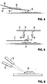
- a piezo-electric crystal is used to detect motion of the follower in the fourth embodiment of the present invention illustrated in Fig. 4.
- a shaped follower 60 is mounted at the distal end of an elongate resilient arm 62 whose proximal end 63 is rigidly mounted.
- a piezo-electric crystal 64 extends along a surface of the arm 62 (in this case the upper surface) and is affixed thereto, so that bending of the arm caused by movement of the follower 60 causes a change of dimension of the piezo-electric crystal, and a consequent voltage between electrical contacts connected to said crystal, which is transmitted via wires 66 to control electronics.
- a transitory voltage is generated each time the follower 60 is moved, allowing the edges of projections or recesses in a card to be detected.
- More sophisticated embodiments can utilise a piezo-electric crystal to generate a continuous signal.
- One such embodiment of the present invention (not illustrated) comprises all of the components shown in Fig. 4 plus a second piezo-electric crystal which is driven by a time varying electrical signal to vibrate the arm 62.
- the vibrations of the arm 62 are modified depending on the position of the follower 60, and on whether the follower is in contact with a surface. For example, contact of the follower 60 reduces the amplitude of the vibrations. Displacement of the follower by projections on a card may further reduce the amplitude.
- the first piezo-electric crystal (labelled 64 in Fig. 4) continuously detects the vibrations, and control electronics of the card reader can interpret variations in the signal from the first piezo-electric crystal to yield information about the shape of the card.
- FIG. 5 A particularly advantageous embodiment of the present invention is illustrated in Fig. 5. Again, this comprises a shaped follower 70 mounted adjacent the distal end of a resiliently bendable arm 72. In this embodiment however, a shutter is provided adjacent the said distal end. The shutter takes the form of an opaque, planar member 74 projecting upwardly from the upper surface of the arm 72.
- the detector further comprises a horizontally extending printed circuit board 76 having first and second downward projections 78,80.
- Mounted on the first downward projection 80 is a light emitter 82, which may be a light emitting diode, and which is positioned to illuminate a light detector 84 mounted on the second downward projection 84.
- the printed circuit board 76 is disposed above the arm 72, and is aligned so that upward movement of the follower 70 causes the shutter to be interposed between the light emitter 82 and the light detector 84. The consequent reduction in light level at the detector is communicated to control electronics.
- a mechanical follower is not essential to the card reader in accordance with the present invention, as the embodiment illustrated in Fig. 6 demonstrates.
- reflected light is used to detect the presence of projections and/or recesses.
- a light emitter 90 is directed toward the surface of a card being read. In the illustrated embodiment, the emitted light is obliquely incident on the card surface.
- a light detector 92 is disposed adjacent the light emitter and is directed to receive light from a direction almost anti-parallel to the direction of the light emitted by the emitter 90.
- the emitted light strikes an angled surface defining the periphery of a projection, it is reflected through almost 180 degrees, towards the light detector.
- the consequent variation of detected light level during scanning of the card is communicated to control electronics.
- a flow of air is used to detect the presence or absence of projections or depressions on the surface of the card being read.
- the air flow is provided by a fan 100 via a pressure vessel 102, which smooths the air flow to flexible supply tubes 104 connected to a reading head 106.
- the reading head of the present embodiment is a cuboid having a lower surface which, in use, lies adjacent a card being scanned, and which is penetrated by vertical through-going bores 108, the upper ends of which are connected to respective supply tubes 104 and are thereby supplied with air while the bottom ends of the bores are open towards the card being scanned.
- a detector may be constructed with a single bore 108 and a single supply tube, the embodiment illustrated, which comprises three supply tubes and three corresponding bores, is preferred for reasons which will be explained below.
- the detector in accordance with the present embodiment of the invention further comprises a pressure transducer 110 arranged to detect pressure in the flexible tubes 104.
- the transducer could, alternatively, be disposed in or on the reading head to detect pressure in the bores 108.
- a card being read is shown at 112 in Fig. 7.
- the card is moved past the reading head in a direction which, in the Figure, is perpendicular to the plane of the paper. Air flowing out of the lower ends of the bores 108 interacts with the surface of the card, generating a back pressure in the supply tubes and in the vertical bores 108 which varies with the distance of the card surface from the bottom ends of the bores 108. Consequently, the total pressure within the tubes (measured by the transducer 110) is indicative of the distance of the lower ends of the bores 108 from the card surface, and varies detectably when projections or recesses of the card traverse the lower ends of the bores.
- the present embodiment may be provided with a single pressure transducer which measures pressure in one or more tubes, or may comprise a plurality of pressure transducers, each measuring pressure in a single respective tube or bore. In either case, the signal(s) from the transducers are electronically interpreted to yield information about the card surface.
- the signal it produces will normally be passed to an electronic controller.
- This controller can further process the signal to establish whether it corresponds to embossed characters of the appropriate form. Where, as in the embodiments shown in Figs. 1 to 6, a single detector is provided, analysis may be made of the start and end positions of the embossed characters and of the number and length of the gaps between embossed projections or depressions.
- a minimum height of the projections or depressions at which a card will be accepted.
- a maximum value of the signal could also be set.
- an embossed character falls into one of a number of groups. For example, it is possible to detect whether a character is a 1, 4 or 7. If an embossed character is found to fall within this group, it can be classed as, say "group A"; any other character is "group B".
- group A any other character is "group B”.
- group B any other character is "group B”.
- the sequence of group A and group B characters can be compared to those read from the magnetic strip for validation. Because of the length of a typical card number, often 18 digits, the A,B sequence goes a long way in verifying reasonably conclusively the embossing with the magnetic stripe.
- the flexibility of the present invention can be greatly increased by providing a plurality of detectors, as in the embodiment already described with reference to Fig. 7 and the further embodiment of the present invention schematically illustrated in Fig. 8.
- three detectors 120 (which may be any of the above described types of detector, or could even take some other form), laterally spaced with regard to the direction of travel of the card (which is left to right in the Figure) are provided to detect the bottom, top and middle or a row of embossed characters 122. By comparing the signals from the three detectors, control electronics may actually read the characters, thereby greatly increasing the security of the card reader.
Abstract
Description
- The present invention is concerned with a device for detecting the use of false cards such as credit cards and bank cards. It is particularly suitable for incorporation into card readers such as the magnetic card readers found in automatic banking and automatic product dispensing machines.
- The use of cards comprising a strip of magnetisable material in which information can be magnetically stored is widespread. Familiar examples are the credit and bank cards which comprise a strip of magnetisable material bearing digital information identifying a bank account. Such cards are also sometimes used in security systems, and also in product dispensing systems, for example for the dispensing of fuel to road vehicles.
- There are several devices in widespread use for reading the information on cards of this type. One of the simplest of these is the "swipe" reader, comprising an elongate slot which is adapted to receive an edge of the card and through which the card is drawn. As the card is drawn through the slot, the magnetic strip passes a magnetic reader by means of which the information on the card is read.
- There are other types of card which carry electronically readable information. One simple type contains an electrically conductive strip which can be severed at a selected point, the unbroken length of the conductor representing, for example, a number of credit units remaining.
- It is widely anticipated that still another type of information bearing card - "smart cards", comprising electronic memory and microprocessors will shortly find applications in a range of fields.
- A problem with cards of the above types is fraud by copying. In the case of cards with a magnetic strip, it is known to produce "white cards" - cards of a suitable size and shape to be received in a reader and bearing a magnetisable strip on which a known identifying code has been recorded. Such cards can, for example, be used to make fraudulent withdrawals from banking machines and fuel dispensers.
- White cards are moderately cheap to produce because they need not have the appearance or the exact outer shape of the original card in order to be accepted by conventional card readers.
- Credit and bank cards have an additional distinctive feature: they are embossed with an identifying number and with other characters, the positioning of some of the embossed characters being subject to an ISO standard. The letters and numerals stand proud of the card surface on one face while the other face bears a corresponding set of recesses.
- It is an object of the present invention to provide a device for detecting the presence or absence of these embossed characters or other projections/depressions on a surface of a card, and a card reader incorporating such a device.
- A further object of the present invention is to provide a device capable of reading information encoded in the embossed characters.
- In accordance with a first aspect of the present invention, there is provided a card reader comprising a detector for detecting raised projections or recesses in a surface of a machine-readable card.
- Preferably, the card reader further comprises machine readable information storage means. This may, for example, take the form of a magnetic reader.
- By checking for projections/recesses, the card reader in accordance with the present invention can detect the use of false cards which lack the surface features (such as embossed lettering) of genuine cards.
- Preferably, signals from the detector are fed to control electronics. In this way, the signals may be subject to tests to establish whether they conform to the pattern expected. For example, in accordance with the present invention, the control electronics may establish whether the ratio of the projections to a card dimension is characteristic of a genuine card.
- Preferably, provision is made for relative motion of the card and the detector. The card may be drawn or propelled past the detector. Such an arrangement would be appropriate eg. for "swipe" readers. Alternatively, means may be provided to move the detector across the card surface.
- Preferably, the detector comprises a mechanical follower which is adapted to contact a surface of a card being read and to be displaced by raised projections or depressions in the card, an electrical signal being controlled in dependence on the displacement of the follower.
- The follower may be biased toward the surface of the card being read.
- Preferably, the follower is mechanically connected to a switch in such a way that displacement of the mechanical follower due to a projection or recess in the card being read causes a change in the state of the switch.
- In accordance with another preferred embodiment of the present invention, the detector further comprises a light source, an optical detector arranged to detect the light from said source and a shutter which is mechanically connected to the follower, wherein displacement of the follower causes a change in the light level at the optical detector.
- The light source may be electrical - most preferably a light emitting diode - or could comprise means for admitting ambient light - eg. an opening or window in a casing.
- The shutter may comprise an opaque member which is movable by the follower into or away from a position between the light source and the follower.
- In accordance with yet another preferred embodiment of the present invention, there is provided a card reader comprising a piezo-electric transducer mechanically connected to the follower so that displacement of the follower changes a stress exerted on the piezo-electric transducer.
- As is well known, a transitory electro-motive force is generated across a piezo-electric crystal when the stress exerted thereon is varied. Thus, a simple detector in accordance with the present invention may comprise a single piezo-electric transducer which generates a signal voltage each time the follower is moved.
- More preferably, however, the detector comprises first and second piezo-electric transducers, a time varying electric signal being applied to the first piezo-electric transducer to produce vibrations which are detected by the second piezo-electric transducer and which are detectably varied by the follower.
- In such a detector, contact of the follower with a surface of the card being read and/or displacement of the follower due to projections or depressions of said card alters the vibrations detected by the first piezo-electric transducer. This alteration can be electronically detected to provide information about the card.
- The detector of the card reader in accordance with the present invention does not have to comprise a mechanical follower.
- In a particularly preferred embodiment of the present invention, the detector comprises a light source positioned to emit light toward a surface of a card being read, a light detector positioned to detect light reflected from the surface of the card, and electronic means for detecting changes in light level at the detector due to raised projections or recesses in the surface of the card.
- Preferably, the light is incident on the surface of the card at an oblique angle.
- In an alternative preferred embodiment, the detector comprises means for providing a flow of air, an air duct which is connected to said means for providing a flow of air and has an opening which, in use, is adjacent a surface of a card being read, and a transducer for detecting changes in the pressure within said air duct.
- In such a detector, variations in back pressure in the air duct are indicative of passage of projections or depressions of the card surface past the opening of the duct. Again, these variations may be interpreted by electronic means.
- Preferably, two or more detectors are provided for detecting raised projections or recesses in a surface of a machine readable card, said detectors being connected to electronic means for interpreting information encoded in said projections or recesses.
- More preferably, three detectors are provided. Preferably, there is motion of the card relative to the detectors in a first direction in use, and the detectors are separated from each other in a second direction which is substantially perpendicular to said first direction.
- Still more preferably, three detectors are positioned to detect upper, middle and lower portions of a line of characters being read.
- In accordance with still a further preferred embodiment of the present invention, the card reader may comprise electronic means connected to the two or more detectors for reading a series of characters embossed on a surface of the card being read.
- In accordance with a further aspect of the present invention, there is provided a detector for use in a card reader, comprising a mechanical follower, a light source, an optical detector arranged to detect the light from the source, and a shutter which is arranged to be displaced by the follower, wherein displacement of the shutter causes a change in the light level at the optical detector.
- Specific embodiments of the present invention will now be described, by way of example only, with reference to the accompanying drawings, in which:-
- Fig. 1 is a front view of a first embodiment of a detector in accordance with the present invention;
- Fig. 2 is a side view of a second embodiment of a detector in accordance with the present invention;
- Fig. 3 shows a third embodiment of a detector in accordance with the present invention in side view;
- Fig. 4 is a side view of a fourth embodiment of a detector in accordance with the present invention;
- Fig. 5 is a side view of a fifth embodiment of a detector in accordance with the present invention;
- Fig. 6 is a side view of a sixth embodiment of a detector in accordance with the present invention;
- Fig. 7 is a side view of a seventh embodiment of a detector in accordance with the present invention; and
- Fig. 8 is a schematic plan view of an eighth embodiment of a detector in accordance with the present invention.
- The illustrations show only those components which are directly related to the detection of projections or depressions in the surface of the card. It is to be understood that the card reader in accordance with the present invention will normally additionally comprise means for enabling relative motion of the card and the detector. For example, this is achieved in a "swipe" reader by the provision of a slot dimensioned to receive an edge of the card; the detector in such a reader would be provided at an internal face of this slot. Alternatively, provision may be made to propel the card past the reader, for example using rollers, or the card may remain stationary while the detector is moved.
- In addition, the card reader in accordance with the present invention will typically comprise means, such as a magnetic reading head, for reading machine-readable information encoded on the card.
- As shown in Fig. 1, a
detector 1 for detecting projections or depressions in a card comprises a switch 2 mounted on a downwardly projecting arm 3 of a bracket 4. The switch 2 comprises a follower 6 which is downwardly spring biased. The state of the switch (whether the switch is "off" or "on") is dependent on the vertical position of the follower.
In Fig 1, a card 8 is shown in the process of being checked. The card is moved in a direction perpendicular to the plane of the paper, so that embossed characters 12 move past the follower 6, which is thereby moved up and down, changing the state of the switch. - During the checking process, a
separation 10 between the switch 2 and the upper surface of the card 8 is defined by the downwardly projecting arm 3, the lower end of which abuts against said upper surface of the card 8. The bracket 4 has a degree of flexibility in order to allow the downwardly projecting arm 3 and hence the switch 2 to be displaced slightly by the card. - If a card without surface projections were passed through the detector shown in Fig. 1, even if the card had an increased thickness, the state of the switch 2 would not be changed since the
separation 10 of the switch from the upper surface of the card would be maintained by the abutment of the lower end of the downwardly projecting arm 3 against the upper surface of the card. - A further specific embodiment of the present invention, again comprising a switch, is shown in Fig. 2 and comprises resiliently deformable upper and
lower arms bracket 24. Adjacent the distal end of theupper arm 20, at the lower surface thereof, is provided aswitch contact 26. Acorresponding switch contact 28 is provided adjacent the distal end of the upper surface of thelower arm 22. Further, a shapedfollower 30 is provided at the lower surface of thelower arm 22, adjacent the distal end thereof. - In use, a
card 32 whose surface bears projections 34 moves past thefollower 30. When thefollower 30 is upwardly displaced by the projections 34, it brings thecontacts - The embodiment illustrated in Fig. 2 could equally well be adapted to detect depressions in the card surface. In such an embodiment of the present invention, the switch could be normally closed by upward pressure exerted on the
follower 30 by the card surface, and be opened when the follower moves downward into depressions. - The third embodiment of the detector in accordance with the present invention shown in Fig. 3 comprises a
follower 40 connected via afollower arm 42 to an electrical or electronic transducer 44. The transducer is electrically connected via anamplifier 46 to anelectronic controller 48.
Thefollower arm 42 is downwardly spring biased so that thefollower 40 stays in contact with the card while the card is drawn past the follower.
In use, thecard 43 is drawn in a direction towards the left or right in Fig. 2. The raisedembossed characters 50 cause displacement of thefollower 40 which in turn causes the transducer 44 to send an electrical signal to the amplifier.
A variety of types of transducer is suitable for this embodiment. The transducer 44 may be in the form of a microphone, in which case vibrations caused by displacement of thefollower 40 are transmitted along thefollower arm 42 and detected by the microphone. Alternatively, the transducer may comprise a piezo-electric crystal, thefollower arm 42 being mounted-in such a way that displacement of thefollower 40 causes a force to be exerted on the piezo-electric crystal. This force may be magnified using mechanical advantage - for example by using a substantially rigid follower arm pivoted about a point close to the piezo-electric crystal and bearing on said crystal. - A piezo-electric crystal is used to detect motion of the follower in the fourth embodiment of the present invention illustrated in Fig. 4.
- As in the Fig. 2 embodiment, a shaped
follower 60 is mounted at the distal end of an elongateresilient arm 62 whoseproximal end 63 is rigidly mounted. A piezo-electric crystal 64 extends along a surface of the arm 62 (in this case the upper surface) and is affixed thereto, so that bending of the arm caused by movement of thefollower 60 causes a change of dimension of the piezo-electric crystal, and a consequent voltage between electrical contacts connected to said crystal, which is transmitted viawires 66 to control electronics. - In the embodiment illustrated in Fig. 4, a transitory voltage is generated each time the
follower 60 is moved, allowing the edges of projections or recesses in a card to be detected. - More sophisticated embodiments can utilise a piezo-electric crystal to generate a continuous signal. One such embodiment of the present invention (not illustrated) comprises all of the components shown in Fig. 4 plus a second piezo-electric crystal which is driven by a time varying electrical signal to vibrate the
arm 62. The vibrations of thearm 62 are modified depending on the position of thefollower 60, and on whether the follower is in contact with a surface. For example, contact of thefollower 60 reduces the amplitude of the vibrations. Displacement of the follower by projections on a card may further reduce the amplitude. - The first piezo-electric crystal (labelled 64 in Fig. 4) continuously detects the vibrations, and control electronics of the card reader can interpret variations in the signal from the first piezo-electric crystal to yield information about the shape of the card.
- A particularly advantageous embodiment of the present invention is illustrated in Fig. 5. Again, this comprises a shaped follower 70 mounted adjacent the distal end of a resiliently
bendable arm 72. In this embodiment however, a shutter is provided adjacent the said distal end. The shutter takes the form of an opaque,planar member 74 projecting upwardly from the upper surface of thearm 72. The detector further comprises a horizontally extending printedcircuit board 76 having first and seconddownward projections downward projection 80 is alight emitter 82, which may be a light emitting diode, and which is positioned to illuminate alight detector 84 mounted on the seconddownward projection 84. The printedcircuit board 76 is disposed above thearm 72, and is aligned so that upward movement of the follower 70 causes the shutter to be interposed between thelight emitter 82 and thelight detector 84. The consequent reduction in light level at the detector is communicated to control electronics. - A mechanical follower is not essential to the card reader in accordance with the present invention, as the embodiment illustrated in Fig. 6 demonstrates. In this embodiment, reflected light is used to detect the presence of projections and/or recesses. A
light emitter 90 is directed toward the surface of a card being read. In the illustrated embodiment, the emitted light is obliquely incident on the card surface. Alight detector 92 is disposed adjacent the light emitter and is directed to receive light from a direction almost anti-parallel to the direction of the light emitted by theemitter 90. - When the emitted light falls on a planar portion of the card surface, it is reflected away from the
detector 92 in the direction shown by fine dottedlines 94 in Fig. 6. - However when, as in the Figure, the emitted light strikes an angled surface defining the periphery of a projection, it is reflected through almost 180 degrees, towards the light detector. The consequent variation of detected light level during scanning of the card is communicated to control electronics.
- In yet another specific embodiment of the present invention illustrated in Fig. 7, a flow of air is used to detect the presence or absence of projections or depressions on the surface of the card being read. The air flow is provided by a
fan 100 via apressure vessel 102, which smooths the air flow toflexible supply tubes 104 connected to areading head 106. As shown, the reading head of the present embodiment is a cuboid having a lower surface which, in use, lies adjacent a card being scanned, and which is penetrated by vertical through-goingbores 108, the upper ends of which are connected torespective supply tubes 104 and are thereby supplied with air while the bottom ends of the bores are open towards the card being scanned. - While a detector may be constructed with a
single bore 108 and a single supply tube, the embodiment illustrated, which comprises three supply tubes and three corresponding bores, is preferred for reasons which will be explained below. - The detector in accordance with the present embodiment of the invention further comprises a
pressure transducer 110 arranged to detect pressure in theflexible tubes 104. The transducer could, alternatively, be disposed in or on the reading head to detect pressure in thebores 108. - A card being read is shown at 112 in Fig. 7. The card is moved past the reading head in a direction which, in the Figure, is perpendicular to the plane of the paper. Air flowing out of the lower ends of the
bores 108 interacts with the surface of the card, generating a back pressure in the supply tubes and in thevertical bores 108 which varies with the distance of the card surface from the bottom ends of thebores 108. Consequently, the total pressure within the tubes (measured by the transducer 110) is indicative of the distance of the lower ends of thebores 108 from the card surface, and varies detectably when projections or recesses of the card traverse the lower ends of the bores. - The present embodiment may be provided with a single pressure transducer which measures pressure in one or more tubes, or may comprise a plurality of pressure transducers, each measuring pressure in a single respective tube or bore. In either case, the signal(s) from the transducers are electronically interpreted to yield information about the card surface.
Although all of the Figures show devices detecting raised projections on a card, all of the embodiments described herein would be suitable for detecting depressions. Clearly, the embodiment shown (for example) in Fig. 1 would require slight modification in that the follower 6 would need to be spring biased to project below the lower end of the downwardly projecting arm 3, so that it would extend into the depressions. - For increased security, devices adapted to detect depressions on one face and projections on the opposite face could be used in conjunction.
- Whatever the exact form of the detector, the signal it produces will normally be passed to an electronic controller. This controller can further process the signal to establish whether it corresponds to embossed characters of the appropriate form. Where, as in the embodiments shown in Figs. 1 to 6, a single detector is provided, analysis may be made of the start and end positions of the embossed characters and of the number and length of the gaps between embossed projections or depressions.
- Additionally, it is possible to set a minimum height of the projections or depressions) at which a card will be accepted. Similarly, in the embodiments in which a variable signal is generated depending on the height of the projections or depression, a maximum value of the signal could also be set.
- In a further development of this invention, it is possible, even using a single detector, to detect whether an embossed character falls into one of a number of groups. For example, it is possible to detect whether a character is a 1, 4 or 7. If an embossed character is found to fall within this group, it can be classed as, say "group A"; any other character is "group B". When the card is being scanned magnetically, it is also scanned for the character sequence on the embossing. Whilst the exact characters are not known, the sequence of group A and group B characters can be compared to those read from the magnetic strip for validation. Because of the length of a typical card number, often 18 digits, the A,B sequence goes a long way in verifying reasonably conclusively the embossing with the magnetic stripe.
- However, the flexibility of the present invention can be greatly increased by providing a plurality of detectors, as in the embodiment already described with reference to Fig. 7 and the further embodiment of the present invention schematically illustrated in Fig. 8.
- In the Fig. 8 embodiment three detectors 120 (which may be any of the above described types of detector, or could even take some other form), laterally spaced with regard to the direction of travel of the card (which is left to right in the Figure) are provided to detect the bottom, top and middle or a row of
embossed characters 122. By comparing the signals from the three detectors, control electronics may actually read the characters, thereby greatly increasing the security of the card reader.
Claims (10)
- A card reader comprising a detector (1) adapted to detect raised projections (12,34,50) or recesses in a surface of a machine-readable card (8,32,43).
- A card reader as claimed in claim 1, wherein the detector comprises a mechanical follower (6,30,40,60,70) which is adapted to contact a surface of a card (8,32,43) being read and to be displaced by raised projections (12,34,50) or depressions in the card, an electrical signal being controlled in dependence on the displacement of the follower (6,30,40,60,70).
- A card reader as claimed in claim 2, wherein the follower (6,30) is mechanically connected to a switch (26,28) in such a way that displacement of the mechanical follower (6,30) due to a projection (12,34) or recess in the card (8,32) being read causes a change in the state of the switch (26,28).
- A card reader as claimed in claim 2, wherein the detector further comprises a light source (82), an optical detector (84) arranged to detect the light from said source (82) and a shutter (74) which is mechanically connected to the follower (70), wherein displacement of the follower causes a change in the light level at the optical detector (84).
- A card reader as claimed in claim 2, further comprising a piezo-electric transducer (64) mechanically connected to the follower (60) so that displacement of the follower (60) changes a stress exerted on the piezo-electric transducer (64).
- A card reader as claimed in claim 1, wherein the detector comprises a light source (90) positioned to emit light toward a surface of a card being read, a light detector (92) positioned to detect light reflected from the surface of the card, and electronic means for reacting to changes in light level at the detector due to raised projections or recesses in the surface of the card.
- A card reader as claimed in claim 1, wherein the detector comprises means (100,102) for providing a flow of air, an air duct (104) which is connected to said means (100,102) for providing a flow of air and has an opening which, in use, is adjacent a surface of a card being read, and a transducer (110) for detecting changes in the pressure within said air duct (104).
- A card reader as claimed in any preceding claim, wherein two or more detectors (120) are provided for detecting raised projections (122) or recesses in a surface of a machine readable card, said detectors being connected to electronic means for interpreting information encoded in said projections or recesses.
- A card reader as claimed in claim 8, wherein there is motion of the card relative to the detectors (120) in a first direction in use, and the detectors (120) are separated from each other in a second direction which is substantially perpendicular to said first direction.
- A detector for use in a card reader, comprising a mechanical follower (70), a light source (82), an optical detector (84) arranged to detect the light from said source, and a shutter (74) which is arranged to be displaced by the follower (70), wherein displacement of the shutter (74) causes a change in the light level at the optical detector (84).
Applications Claiming Priority (2)
| Application Number | Priority Date | Filing Date | Title |
|---|---|---|---|
| GB9413121 | 1994-06-30 | ||
| GB9413121A GB9413121D0 (en) | 1994-06-30 | 1994-06-30 | Device for detecting the use of false cards |
Publications (2)
| Publication Number | Publication Date |
|---|---|
| EP0690402A2 true EP0690402A2 (en) | 1996-01-03 |
| EP0690402A3 EP0690402A3 (en) | 1998-01-14 |
Family
ID=10757557
Family Applications (1)
| Application Number | Title | Priority Date | Filing Date |
|---|---|---|---|
| EP95304607A Ceased EP0690402A3 (en) | 1994-06-30 | 1995-06-29 | Device for detecting the use of false cards |
Country Status (3)
| Country | Link |
|---|---|
| US (1) | US5814800A (en) |
| EP (1) | EP0690402A3 (en) |
| GB (1) | GB9413121D0 (en) |
Cited By (1)
| Publication number | Priority date | Publication date | Assignee | Title |
|---|---|---|---|---|
| EP1107175A2 (en) * | 1999-12-10 | 2001-06-13 | Sony Corporation | Embossed IC card and information reading system therefor |
Families Citing this family (3)
| Publication number | Priority date | Publication date | Assignee | Title |
|---|---|---|---|---|
| US6615194B1 (en) * | 1998-06-05 | 2003-09-02 | Lucent Technologies Inc. | System for secure execution of credit based point of sale purchases |
| JP2003085525A (en) * | 2001-09-13 | 2003-03-20 | Konica Corp | Ic card, and card authentication method |
| DE102015212265B4 (en) * | 2015-07-01 | 2017-05-04 | Carl Zeiss Industrielle Messtechnik Gmbh | Component for a coordinate measuring machine with feature for mapping data |
Family Cites Families (11)
| Publication number | Priority date | Publication date | Assignee | Title |
|---|---|---|---|---|
| US3743817A (en) * | 1970-11-12 | 1973-07-03 | Audac Corp | Data card terminal |
| US3763355A (en) * | 1971-12-29 | 1973-10-02 | Texas Instruments Inc | Dynamic position-actuated card reader |
| US3705416A (en) * | 1971-12-29 | 1972-12-05 | Texas Instruments Inc | Method of operating a computer to read information from cards |
| US3814905A (en) * | 1972-08-22 | 1974-06-04 | Amron Res & Dev Corp | Embossed card reader |
| US3917925A (en) * | 1974-05-10 | 1975-11-04 | Rca Corp | Embossed character reader |
| US4119270A (en) * | 1976-09-14 | 1978-10-10 | Dynetics Engineering Corp. | Embossed character reader |
| US4845770A (en) * | 1986-11-20 | 1989-07-04 | Oki Electric Industry Co., Ltd. | Method and apparatus for processing embossed card |
| DE3801378A1 (en) * | 1987-01-23 | 1988-08-04 | Oki Electric Ind Co Ltd | METHOD AND DEVICE FOR THE PROCESSING OF EMBOSSED CARDS |
| US5428210A (en) * | 1992-01-10 | 1995-06-27 | National Bancard Corporation | Data card terminal with embossed character reader and signature capture |
| US5334823A (en) * | 1992-01-10 | 1994-08-02 | National Bancard Corporation | Systems and methods for operating data card terminals for transaction chargeback protection |
| US5369263A (en) * | 1992-10-30 | 1994-11-29 | Microbilt Corporation | Embossed card reader |
-
1994
- 1994-06-30 GB GB9413121A patent/GB9413121D0/en active Pending
-
1995
- 1995-06-29 EP EP95304607A patent/EP0690402A3/en not_active Ceased
- 1995-06-30 US US08/497,226 patent/US5814800A/en not_active Expired - Fee Related
Non-Patent Citations (1)
| Title |
|---|
| None |
Cited By (2)
| Publication number | Priority date | Publication date | Assignee | Title |
|---|---|---|---|---|
| EP1107175A2 (en) * | 1999-12-10 | 2001-06-13 | Sony Corporation | Embossed IC card and information reading system therefor |
| EP1107175A3 (en) * | 1999-12-10 | 2002-05-22 | Sony Corporation | Embossed IC card and information reading system therefor |
Also Published As
| Publication number | Publication date |
|---|---|
| US5814800A (en) | 1998-09-29 |
| EP0690402A3 (en) | 1998-01-14 |
| GB9413121D0 (en) | 1994-08-24 |
Similar Documents
| Publication | Publication Date | Title |
|---|---|---|
| US5682103A (en) | Infrared detection of authenticity of security documents comprising electromagnetic particles | |
| US5173597A (en) | Card reader with tapered card slot guide surface | |
| JP2660912B2 (en) | Banknote security thread confirmation device | |
| US3639905A (en) | Credit card system having means for sensing if object is living | |
| US5434427A (en) | Currency verification device | |
| US20080315989A1 (en) | Security functionality for magnetic card readers and point of sales devices | |
| US20050111708A1 (en) | Sweep-type fingerprint sensor device capable of guiding a finger in a fixed sweeping direction | |
| RU94040373A (en) | DEVICE FOR REGISTRATION OF SIGNS OF INFORMATION PRINTED ON DOCUMENTS (OPTIONS) | |
| US6616043B2 (en) | Multi sensor information reader | |
| US5814800A (en) | Device for detecting the use of false cards by reading embossed characters | |
| US5810146A (en) | Wide edge lead currency thread detection system | |
| US4673368A (en) | Toy bank with novel coin discriminating mechanism | |
| US6216843B1 (en) | Apparatus for taking out information using magnetic sensor and carrying out test of article by using that information | |
| EP0837414B1 (en) | Magnetic card sensor | |
| US3814905A (en) | Embossed card reader | |
| RU2155989C2 (en) | Method and device for checking documents, which are protection against faking | |
| JPH09237362A (en) | Electrostatic capacity sensor and paper money recognition device | |
| WO1990006070A1 (en) | Toy bank with novel coin discriminating mechanism | |
| US6079705A (en) | Method and apparatus for verifying the integrity of a mail piece | |
| US5764054A (en) | Contiguously matched magnetic sensor array and magnetic media for authentication of documents and products | |
| WO1995026537A2 (en) | Method and means for reading a permanent bar code | |
| CN216310906U (en) | Currency detector with bar code reading function | |
| JPH08180239A (en) | Apparatus and method for discrimination of document | |
| US8141779B1 (en) | Sensor and markers for speed feedback in a hand-operated document reader/imager | |
| JPH0235586A (en) | Ic card reader |
Legal Events
| Date | Code | Title | Description |
|---|---|---|---|
| PUAI | Public reference made under article 153(3) epc to a published international application that has entered the european phase |
Free format text: ORIGINAL CODE: 0009012 |
|
| AK | Designated contracting states |
Kind code of ref document: A2 Designated state(s): BE DE FR GB IT NL |
|
| PUAL | Search report despatched |
Free format text: ORIGINAL CODE: 0009013 |
|
| AK | Designated contracting states |
Kind code of ref document: A3 Designated state(s): BE DE FR GB IT NL |
|
| 17P | Request for examination filed |
Effective date: 19981005 |
|
| 17Q | First examination report despatched |
Effective date: 19991126 |
|
| GRAG | Despatch of communication of intention to grant |
Free format text: ORIGINAL CODE: EPIDOS AGRA |
|
| STAA | Information on the status of an ep patent application or granted ep patent |
Free format text: STATUS: THE APPLICATION HAS BEEN REFUSED |
|
| 18R | Application refused |
Effective date: 20011011 |