EP0689976A1 - Operating angle adjusting structure for wiper - Google Patents
Operating angle adjusting structure for wiper Download PDFInfo
- Publication number
- EP0689976A1 EP0689976A1 EP95303661A EP95303661A EP0689976A1 EP 0689976 A1 EP0689976 A1 EP 0689976A1 EP 95303661 A EP95303661 A EP 95303661A EP 95303661 A EP95303661 A EP 95303661A EP 0689976 A1 EP0689976 A1 EP 0689976A1
- Authority
- EP
- European Patent Office
- Prior art keywords
- wiper
- axis
- ball joint
- link
- operating angle
- Prior art date
- Legal status (The legal status is an assumption and is not a legal conclusion. Google has not performed a legal analysis and makes no representation as to the accuracy of the status listed.)
- Granted
Links
- 230000002093 peripheral effect Effects 0.000 claims description 7
- 230000002265 prevention Effects 0.000 claims 1
- 238000003754 machining Methods 0.000 abstract description 9
- 238000004519 manufacturing process Methods 0.000 description 8
- 230000008878 coupling Effects 0.000 description 7
- 238000010168 coupling process Methods 0.000 description 7
- 238000005859 coupling reaction Methods 0.000 description 7
- 230000002452 interceptive effect Effects 0.000 description 5
- 238000000034 method Methods 0.000 description 3
- 238000004904 shortening Methods 0.000 description 3
- 230000005540 biological transmission Effects 0.000 description 1
Images



Classifications
-
- B—PERFORMING OPERATIONS; TRANSPORTING
- B60—VEHICLES IN GENERAL
- B60S—SERVICING, CLEANING, REPAIRING, SUPPORTING, LIFTING, OR MANOEUVRING OF VEHICLES, NOT OTHERWISE PROVIDED FOR
- B60S1/00—Cleaning of vehicles
- B60S1/02—Cleaning windscreens, windows or optical devices
- B60S1/04—Wipers or the like, e.g. scrapers
- B60S1/06—Wipers or the like, e.g. scrapers characterised by the drive
- B60S1/16—Means for transmitting drive
- B60S1/18—Means for transmitting drive mechanically
- B60S1/24—Means for transmitting drive mechanically by rotary cranks
-
- F—MECHANICAL ENGINEERING; LIGHTING; HEATING; WEAPONS; BLASTING
- F16—ENGINEERING ELEMENTS AND UNITS; GENERAL MEASURES FOR PRODUCING AND MAINTAINING EFFECTIVE FUNCTIONING OF MACHINES OR INSTALLATIONS; THERMAL INSULATION IN GENERAL
- F16C—SHAFTS; FLEXIBLE SHAFTS; ELEMENTS OR CRANKSHAFT MECHANISMS; ROTARY BODIES OTHER THAN GEARING ELEMENTS; BEARINGS
- F16C3/00—Shafts; Axles; Cranks; Eccentrics
- F16C3/04—Crankshafts, eccentric-shafts; Cranks, eccentrics
- F16C3/22—Cranks; Eccentrics
- F16C3/28—Adjustable cranks or eccentrics
-
- F—MECHANICAL ENGINEERING; LIGHTING; HEATING; WEAPONS; BLASTING
- F16—ENGINEERING ELEMENTS AND UNITS; GENERAL MEASURES FOR PRODUCING AND MAINTAINING EFFECTIVE FUNCTIONING OF MACHINES OR INSTALLATIONS; THERMAL INSULATION IN GENERAL
- F16C—SHAFTS; FLEXIBLE SHAFTS; ELEMENTS OR CRANKSHAFT MECHANISMS; ROTARY BODIES OTHER THAN GEARING ELEMENTS; BEARINGS
- F16C2326/00—Articles relating to transporting
- F16C2326/01—Parts of vehicles in general
- F16C2326/09—Windscreen wipers, e.g. pivots therefore
-
- Y—GENERAL TAGGING OF NEW TECHNOLOGICAL DEVELOPMENTS; GENERAL TAGGING OF CROSS-SECTIONAL TECHNOLOGIES SPANNING OVER SEVERAL SECTIONS OF THE IPC; TECHNICAL SUBJECTS COVERED BY FORMER USPC CROSS-REFERENCE ART COLLECTIONS [XRACs] AND DIGESTS
- Y10—TECHNICAL SUBJECTS COVERED BY FORMER USPC
- Y10T—TECHNICAL SUBJECTS COVERED BY FORMER US CLASSIFICATION
- Y10T403/00—Joints and connections
- Y10T403/32—Articulated members
- Y10T403/32606—Pivoted
- Y10T403/32951—Transverse pin or stud
-
- Y—GENERAL TAGGING OF NEW TECHNOLOGICAL DEVELOPMENTS; GENERAL TAGGING OF CROSS-SECTIONAL TECHNOLOGIES SPANNING OVER SEVERAL SECTIONS OF THE IPC; TECHNICAL SUBJECTS COVERED BY FORMER USPC CROSS-REFERENCE ART COLLECTIONS [XRACs] AND DIGESTS
- Y10—TECHNICAL SUBJECTS COVERED BY FORMER USPC
- Y10T—TECHNICAL SUBJECTS COVERED BY FORMER US CLASSIFICATION
- Y10T74/00—Machine element or mechanism
- Y10T74/20—Control lever and linkage systems
- Y10T74/20576—Elements
- Y10T74/20582—Levers
- Y10T74/206—Adjustable
-
- Y—GENERAL TAGGING OF NEW TECHNOLOGICAL DEVELOPMENTS; GENERAL TAGGING OF CROSS-SECTIONAL TECHNOLOGIES SPANNING OVER SEVERAL SECTIONS OF THE IPC; TECHNICAL SUBJECTS COVERED BY FORMER USPC CROSS-REFERENCE ART COLLECTIONS [XRACs] AND DIGESTS
- Y10—TECHNICAL SUBJECTS COVERED BY FORMER USPC
- Y10T—TECHNICAL SUBJECTS COVERED BY FORMER US CLASSIFICATION
- Y10T74/00—Machine element or mechanism
- Y10T74/21—Elements
- Y10T74/211—Eccentric
- Y10T74/2114—Adjustable
-
- Y—GENERAL TAGGING OF NEW TECHNOLOGICAL DEVELOPMENTS; GENERAL TAGGING OF CROSS-SECTIONAL TECHNOLOGIES SPANNING OVER SEVERAL SECTIONS OF THE IPC; TECHNICAL SUBJECTS COVERED BY FORMER USPC CROSS-REFERENCE ART COLLECTIONS [XRACs] AND DIGESTS
- Y10—TECHNICAL SUBJECTS COVERED BY FORMER USPC
- Y10T—TECHNICAL SUBJECTS COVERED BY FORMER US CLASSIFICATION
- Y10T74/00—Machine element or mechanism
- Y10T74/21—Elements
- Y10T74/2142—Pitmans and connecting rods
- Y10T74/2153—Sheet metal type
Definitions
- the present invention relates to an operating angle adjusting structure for a wiper for wiping windshield surfaces of motor vehicles such as automobiles, buses and trucks.
- a wiper has a wiper arm which is driven by a motor to reciprocally swing for wiping a windshield surface. It is desirable for a wiper to have a greater wiping angle for providing a wider field of view.
- the wiping angle of a wiper arm is determined by an axis-to-axis distance between an axis of a turnable shaft at a proximal end side of a link member and a center axis of a ball joint at a distal end side thereof, the link member being disposed in a power transmission path extending from a motor to a wiper shaft. The longer the axis-to-axis distance, the greater the wiping angle.
- the wiping angle is maximized. Due to manufacturing errors caused when machining and mounting the turnable shaft and the ball joint to the link member, however, the wiping angle may exceed the maximum axis-to-axis distance. This raises a problem that the wiping angle of the wiper arm is increased to such an extent so as to interfere with a pillar.
- the above problem can be avoided by employing special precision machining which provides higher accuracy than usual, when machining and mounting the turnable shaft and the ball joint to the link member, or by shortening the axis-to-axis distance in anticipation of the manufacture errors.
- the former method has poor production efficiency and requires a special precision machining apparatus, thus increasing the equipment cost.
- the latter method is free from the problems of the former method, but the wiping angle is necessarily reduced.
- An opposing type wiper comprises a crank arm rotatably driven by a motor, an intermediate link pivotally supported at a middle position, and a connecting rod disposed between the crank arm and the intermediate link for converting a rotating motion of the crank arm into a reciprocal swing motion of the intermediate link.
- upper and lower ends of the intermediate link are connected respectively to right and left wiper shafts via drive rods, causing right and left wiper arms to be operated for wiping the windshield surface in oppositely moving relation.
- changes in angular speeds of the right and left wiper arms are set to be asymmetrical therebetween so that wiper blades of the right and left wiper arms are overlapped with each other in their lower inverting positions.
- the right and left wiper blades are laid one above the other without interfering with each other, by setting the angular speed of the overlying wiper arm (on the side of a driver's seat) to be larger than that of the underlying wiper arm (on the side of an assistant's seat) in the vicinity of the lower inverting positions.
- the opposing type wiper includes many components, and even a small error significantly affects the wiping angle and often leads to a risk that the wiper arms may interfere with each other. Also, because the angular speeds of the wiper arms are intentionally made different between the driver's side and the passenger's side, high accuracy is required in setting of the components and setting errors result in a significant influence.
- the object of the present invention is to provide an operating angle adjusting structure for a wiper which can overcome the drawbacks described above.
- the present invention provides an operating angle adjusting structure for a wiper having a ball joint disposed in one end portion of a link member and a ball retainer disposed on a connecting rod.
- the ball retainer is supported by the ball joint in such a manner as to rotate through a spherical slide contact.
- the ball joint is integrally mounted to one surface of an adjusting member.
- the adjusting member is attached to one surface of the link member and is rotatable for adjustment through a setting shaft fixedly inserted in the ball joint at an eccentric position with respect to the center axis of the ball joint.
- an anti-rotation assembly is provided for checking rotation of the adjusting member after adjustment.
- the anti-rotation assembly is disposed between the other surface of the adjusting member and the one surface of the link member opposing each other.
- a maximally wide wiping angle can be realized within the range such that the wiper arms will not interfere with the window pillars and each other, without requiring a precision machining apparatus.
- the wiper 1 comprises a motor 2 equipped with an integral speed reducing mechanism.
- a crank arm 3 is integrally mounted to an output shaft of the motor 2 for rotation with the output shaft.
- An intermediate link 4 is pivotally supported at a middle position about a pivot 4a.
- a connecting rod 5 is coupled between a lower end of the intermediate link 4 and a distal end of the crank arm 3.
- a pair of right and left wiper drive shafts 6 are disposed laterally, one on either side of the intermediate link 4.
- a right drive rod 8 is coupled between a drive link 7 of the right wiper drive shaft 6 and an upper end of the intermediate link 4.
- a left drive rod 9 is coupled between a drive link 7 of the left wiper drive shaft 6 and a lower end of the intermediate link 4.
- a pair of right and left wiper arms 10 are integrally mounted to the right and left wiper drive shafts 6, respectively.
- the rotating motion of the crank arm 3 driven by the motor 2 is converted into a reciprocal swing motion of the intermediate link 4 through the coupling of the crank arm 3 to the connecting rod 5.
- the drive links 7 of the right and left wiper drive shafts 6 which are operatively coupled to the upper and lower ends of the intermediate link 4 through the drive rods 8 and 9, respectively, are turned to operate the wiper arms 10 joined to the right and left wiper drive shaft 6 for wiping the windshield surface in oppositely moving relation.
- the angular speeds of the left and right wiper arms 10 are set to change asymmetrically therebetween in the vicinity of their lower inverting positions, as described later, so that wiper blades 11 overlap vertically in the lower inverting position without interfering with each other.
- the right wiper blade 11 on the driver's seat side (Dr) overlies the left wiper blade 11 on the passenger's seat side.
- a drive unit 12 is constructed by integrally mounting the motor 2 and the pivot point 4a of the intermediate link 4 to a motor bracket 13.
- the crank arm 3, the connecting rod 5 and the intermediate link 4 are also mounted to the drive unit 12.
- the length of the connecting rod 5 and its coupling position to the intermediate link i.e., the distance and the phase angle with respect to the link pivot point) are set so that the actual angular speed of the intermediate link 4 is changed substantially symmetrically between the right and left sides.
- a pair of right and left wiper shaft sleeves 14 is constructed by mounting the wiper drive shaft 6 and the drive link 7 to a wiper shaft bracket 15.
- the wiper shaft sleeves 14 are disposed in respective positions laterally of the drive unit 12 to the right and left.
- the wiper shaft sleeves 14 are operatively coupled to the intermediate link 4 through the drive rods 8 and 9.
- the lengths of the drive rods 8 and 9 and their coupling positions to the intermediate link 4 are set so that angular speeds of the right and left wiper arms 10 are changed asymmetrically between the right and left sides.
- the wiper blades 11 of the right and left wiper arms 10 are laid one above the other at the lower inverting positions without interfering with each other.
- Each of the wiper drive shafts 6 is integrally fixed to a proximal end of a link body 7a of the drive link 7.
- An attachment hole 7b is bored in one end portion of the link body 7a, and the one end portion of the link body 7a has a peripheral edge 7c formed into an arc shape concentric with the attachment hole 7b.
- a joint assembly 16 for coupling the link body 7a and each of the right and left drive rods 8 and 9 comprises a ball joint 16a attached to the one end portion of the link body 7a.
- a ball retainer 16b integrally provided on each of the right and left drive rods 8 and 9 is fitted over the ball joint 16a so that it can rotate through a spherical slide contact.
- the ball joint 16a is attached to one surface of the link body 7a in such a manner that it is eccentric with respect to the attachment hole 7b by a distance ⁇ . More specifically, a proximal end of the ball joint 16a is integrally attached to one surface of a plate-like adjusting member 16c. A screw hole 16d to which a screw pin 17 (described below) for fixing the ball joint 16a is inserted is bored in each of the adjusting member 16c and the ball joint 16a at a position eccentric with respect to the center axis of the ball joint 16a by the distance ⁇ .
- the ball joint 16a may be mounted to one surface of the link body 7a by placing the adjusting member 16c into abutment against one surface of the link body 7a.
- the screw pin 17 is screwed into the link body 7a until it penetrates and enters the screw holes 16d in the adjusting member 16c and the ball joint 16a.
- the axis-to-axis distance D between the center axis of the ball joint 16a and the axis of the wiper shaft 6 can be adjusted by turning the adjusting member 16c about the axis of the screw pin 17 in a condition when the screw pin 17 has been loosened.
- the adjusting member 16c has a peripheral edge with an arc shape concentric with the screw hole 16d.
- the adjusting member 16c has a plurality of rectangular anti-rotation projections 16e formed in a radial pattern on a surface of the adjusting member 16c.
- the projections 16e may have a rectangular cross section, as shown in Fig. 6(D).
- the link body 7a has a plurality of recesses 7d formed on a surface in a radial pattern to receive the anti-rotation projections 16e.
- the projections 16e when located within the recesses 7d prevent the adjusting member 16c attached to the link body 7a from rotating.
- the rectangular projections may extend from the linkbody 7a and engage recesses in the adjusting member 16c.
- a position adjusting tongue 16f projects from a peripheral edge of the adjusting member 16c to extend in a radial direction Y passing the center O of the screw hole 16d substantially perpendicularly to a straight line X that passes the center O of the screw hole 16d and the center axis P of the ball joint 16a.
- the tongue 16f is bent toward the other surface of the link body 7a and has a nearly L-shape of which leg is extended facing the peripheral edge 7c of the one end portion of the link body 7a.
- the position of the ball joint 16a can be adjusted within a range Z exceeding 180 degrees.
- the tongue 16f comes into abutment against the respective side edges of the link body 7a limiting the adjusting range of the joint ball 16a.
- a notch 16g is formed in a distal end of the tongue 16f.
- the position of the ball joint 16a may be adjusted by inserting a tool such as a screwdriver into the notch 16g.
- graduations 7e numbered from “1" to “9” indicate respective positions of the tongue 16f for adjustment.
- the link body 7a is stepwisely curved at an intermediate portion such that one surface of the link body 7a is recessed toward the opposite surface thereof by a distance corresponding to the thickness C of the adjusting member 16c.
- the one surface of the link body 7a at the end adjacent the wiper drive shaft 6 is substantially flush with the one surface of the adjusting member 16c.
- the connecting rod 5, which operatively couples the crank arm 3 driven by the motor to rotate and the intermediate link 4 coupled to the right and left wiper drive shafts 6 through the drive rods 8 and 9, is set in its length and its coupling positions to the intermediate link 4 so as to change the actual angular speed of the intermediate link 4 substantially symmetrically between the right and left sides.
- the angular speeds of the right and left wiper arms 10 are changed asymmetrically between the right and left sides based on setting of the lengths of the drive rods 8 and 9 and setting of their coupling positions to the intermediate link 4.
- the right and left wiper arms 10 are operated to swing reciprocally, causing the wiper blades 11 to wipe the windshield surface W.
- the ball joint 16a attached in an eccentric condition is turned about the center of the screw hole 16d to adjust the axis-to-axis distance between the ball joint 16a and the wiper drive shaft 6 for thereby absorbing the manufacturing errors.
- the wiping angle can be set to an ideal value depending on an extent of the windshield surface, an angle of the windshield surface with respect to the vehicle body, etc. within the range where the wiper arms will not interfere with the window pillars and each other.
- the ideal wiping angle initially intended can be easily realized without reducing the wiping angle, i.e., shortening the axis-to-axis distance, to prevent the wiper arms from interfering with the window pillars and each other, nor requiring special precision machining that has poor production efficiency.
- the position of the ball joint 16a is prevented from rotating by engagement between the rectangular projections 16e on the adjusting member 16c and the recesses 7d formed in the link body 7a.
- the rotational force produced is borne by vertical walls of the rectangular projections 16e and recesses 7d engaging each other. Accordingly, the ball joint 16a is prevented from deviating from its adjusted position, resulting in high reliability.
- the ball joint 16a is positioned and prevented from rotating by the screw pin 17 by which the ball joint 16a is fixed to the link body 7a and the engagement of the rectangular projections 16e with recesses 7d.
- the stresses produced by the rotating force and the pushing/pulling force exerted on the joint ball 16a are not concentrated on one point, but borne in a distributed manner.
- the rotating force is borne by the rectangular projections 16e and recesses 7d engaging with each other, and the pushing/pulling force is borne by the screw pin 17 fixedly screwed in place.
- the wiper has superior durability.
- the adjusting member 16c can be conveniently adjusted by using the tongue 16f projecting from the adjusting member 16c. Since the notch 16g is formed in the tongue 16f, the adjustment can be made by inserting a tool such as a screwdriver to the notch 16g. The adjusting operation can be easily performed even in a condition where the wiper is assembled on the vehicle body and it is difficult for an assemblyman to access to the tongue 16f by a finger.
- the tongue 16f projects in the radial direction Y of the screw hole 16d substantially perpendicular to the straight line X that passes the center O of the screw hole 16d and the center axis P of the ball joint 16a.
- the center axis P of the joint ball 16a is positioned, as shown in Fig. 4, at the central position of the adjustment range, i.e., with the tongue 16f set to the position of the number "5" on the gradations.
- the axis-to-axis distance between the axis Q of the wiper drive shaft 6 and the center axis P of the ball joint 16a is substantially equal to the distance D between the center O of the screw hole 16d and the axis Q of the wiper drive shaft 6.
- the center axis P of the ball joint 16a is displaced toward the wiper drive shaft 6 while following the path in the form of an arc-shaped line about the center O of the screw hole 16d, as shown in Fig. 7. Accordingly, the axis-to-axis distance between the axis Q of the wiper drive shaft 6 and the center axis P of the ball joint 16a can be adjusted to become shorter (i.e., increasing the wiping angle of the wiper arm).
- the amount by which the axis-to-axis distance is adjusted is maximized when the tongue 16f is swung from the central position to the number "9" on the gradations by 90 degrees.
- the maximum amount of adjustment corresponds to the eccentricity a of the ball joint 16a.
- the axis-to-axis distance can be adjusted to become longer (i.e., reducing the wiping angle of the wiper arm) by a distance corresponding to the maximum eccentricity a.
- the axis-to-axis distance can be adjusted totally by an amount twice the eccentricity a, which is advantageous in providing a wide adjustment range.
- the adjustment of the axis-to-axis distance is restricted by tongue 16f abutting the link body 7a in such a manner as not to exceed the positions between which the amount of adjustment is doubled (i.e., the positions of numbers "1" and "9" on the gradations).
- the gradations are numbered by integers from “1” to “9", to avoid misreading by the assemblyman which may occur when the scale is graduated by "0" at the central value and then "+1" to "+4" and “-1” to "-4" successively from "0" on each side.
- the tongue 16f is bent toward the other surface of the link body 7a to have substantially an L-shape and the peripheral edge 7c of the one end portion of the link body 7a is in the form of an arc about the center of the screw hole 16d.
- the adjusting operation can be performed by turning the tongue 16f along the arc-shaped peripheral edge 7c with good working efficiency. Since the gradations 7e are formed on the other surface of the link body 7a, the assemblyman can recognize the adjustment position in a quantitative manner by looking at the graduations 7e. As a result, the axis-to-axis distance can be easily adjusted with higher accuracy.
- the link body 7a is stepwisely curved in its intermediate portion such that the one surface of the link body is recessed toward the other surface thereof by a distance corresponding to the thickness C of the adjusting member 16c.
- the one surface of the link body 7a on the same side as the wiper drive shaft 6 is kept substantially flush with the one surface of the adjusting member 16c.
- the link body 7a can be flat on the side of one surface thereof even with the presence of the adjusting member 16c thereon.
- the present invention is not limited to the above-described embodiment.
- the present invention is also applicable to a ball joint by which a connecting rod is coupled to, rather than the drive link, a drive arm having a proximal end integrally fixed to the output shaft of the wiper motor.
- the output shaft corresponds to the wiper shaft and the crank arm corresponds to the wiper link.
- the present invention is similarly applicable to a ball joint for the intermediate link.
- the axis-to-axis distance between the ball joint and the wiper drive shaft can be adjusted by turning the ball joint to which the connecting rod is coupled in such a manner that it can rotate through a spherical slide contact, about the axis of the screw pin by which the ball joint is attached to the link member.
- the manufacturing errors can be absorbed and the wiping angle of each wiper arm can be set to a maximum value depending on an extent of the windshield surface, an angle of the windshield surface with respect to the vehicle body, etc. within the range where the wiper arms will not interfere with the window pillars and each other.
- the maximum wiping angle initially intended can be easily realized without reducing the wiping angle, i.e., shortening the axis-to-axis distance, to prevent the wiper arms from interfering with the window pillars and each other, nor requiring special precision machining that has poor production efficiency.
Landscapes
- Engineering & Computer Science (AREA)
- General Engineering & Computer Science (AREA)
- Mechanical Engineering (AREA)
- Ocean & Marine Engineering (AREA)
- Transmission Devices (AREA)
- Pivots And Pivotal Connections (AREA)
Abstract
Description
- The present invention relates to an operating angle adjusting structure for a wiper for wiping windshield surfaces of motor vehicles such as automobiles, buses and trucks.
- Generally, a wiper has a wiper arm which is driven by a motor to reciprocally swing for wiping a windshield surface. It is desirable for a wiper to have a greater wiping angle for providing a wider field of view. The wiping angle of a wiper arm is determined by an axis-to-axis distance between an axis of a turnable shaft at a proximal end side of a link member and a center axis of a ball joint at a distal end side thereof, the link member being disposed in a power transmission path extending from a motor to a wiper shaft. The longer the axis-to-axis distance, the greater the wiping angle. From this standpoint, it is desirable to set the axis-to-axis distance so that the wiping angle is maximized. Due to manufacturing errors caused when machining and mounting the turnable shaft and the ball joint to the link member, however, the wiping angle may exceed the maximum axis-to-axis distance. This raises a problem that the wiping angle of the wiper arm is increased to such an extent so as to interfere with a pillar.
- The above problem can be avoided by employing special precision machining which provides higher accuracy than usual, when machining and mounting the turnable shaft and the ball joint to the link member, or by shortening the axis-to-axis distance in anticipation of the manufacture errors. However, the former method has poor production efficiency and requires a special precision machining apparatus, thus increasing the equipment cost. On the other hand, the latter method is free from the problems of the former method, but the wiping angle is necessarily reduced.
- An opposing type wiper comprises a crank arm rotatably driven by a motor, an intermediate link pivotally supported at a middle position, and a connecting rod disposed between the crank arm and the intermediate link for converting a rotating motion of the crank arm into a reciprocal swing motion of the intermediate link. Further, upper and lower ends of the intermediate link are connected respectively to right and left wiper shafts via drive rods, causing right and left wiper arms to be operated for wiping the windshield surface in oppositely moving relation. Additionally, changes in angular speeds of the right and left wiper arms are set to be asymmetrical therebetween so that wiper blades of the right and left wiper arms are overlapped with each other in their lower inverting positions. Specifically, the right and left wiper blades are laid one above the other without interfering with each other, by setting the angular speed of the overlying wiper arm (on the side of a driver's seat) to be larger than that of the underlying wiper arm (on the side of an assistant's seat) in the vicinity of the lower inverting positions.
- Thus, the opposing type wiper includes many components, and even a small error significantly affects the wiping angle and often leads to a risk that the wiper arms may interfere with each other. Also, because the angular speeds of the wiper arms are intentionally made different between the driver's side and the passenger's side, high accuracy is required in setting of the components and setting errors result in a significant influence.
- In view of the foregoing state of the art, the object of the present invention is to provide an operating angle adjusting structure for a wiper which can overcome the drawbacks described above. Specifically, the present invention provides an operating angle adjusting structure for a wiper having a ball joint disposed in one end portion of a link member and a ball retainer disposed on a connecting rod. The ball retainer is supported by the ball joint in such a manner as to rotate through a spherical slide contact. The ball joint is integrally mounted to one surface of an adjusting member. The adjusting member is attached to one surface of the link member and is rotatable for adjustment through a setting shaft fixedly inserted in the ball joint at an eccentric position with respect to the center axis of the ball joint.
- In the above operating angle adjusting structure, preferably, an anti-rotation assembly is provided for checking rotation of the adjusting member after adjustment. The anti-rotation assembly is disposed between the other surface of the adjusting member and the one surface of the link member opposing each other.
- With the present invention arranged as set forth above, a maximally wide wiping angle can be realized within the range such that the wiper arms will not interfere with the window pillars and each other, without requiring a precision machining apparatus.
- The invention will be described now by way of example only, with particular reference to the accompanying drawings. In the drawings:
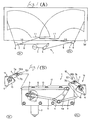
- Fig. 1(A) is a schematic front view of an opposing type wiper, and Fig. 1(B) is a front view of principal parts of the wiper.
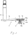
- Fig. 2 is a perspective view of a drive link mechanism.Fig. 3 is a front view of the drive link mechanism with a drive link partly broken away.
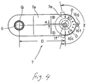
- Fig. 4 is a plan view of the drive link.
- Fig. 5 is a bottom view of the drive link.
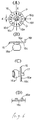
- Fig. 6(A) is a front view of a ball joint, Fig. 6(B) is a plan view of the ball joint, Fig. 6(C) is a side view of the ball joint partly broken, and Fig. 6(D) is a sectional view, in the developed form, of an adjusting member having projections.
- Fig. 7 is a view of a mechanism for adjusting an eccentric condition.
- An embodiment of the present invention will be described below with reference to the accompanying drawings. In the drawings, denoted by 1 is an opposing type wiper. The
wiper 1 comprises amotor 2 equipped with an integral speed reducing mechanism. Acrank arm 3 is integrally mounted to an output shaft of themotor 2 for rotation with the output shaft. Anintermediate link 4 is pivotally supported at a middle position about apivot 4a. A connectingrod 5 is coupled between a lower end of theintermediate link 4 and a distal end of thecrank arm 3. A pair of right and leftwiper drive shafts 6 are disposed laterally, one on either side of theintermediate link 4. Aright drive rod 8 is coupled between adrive link 7 of the rightwiper drive shaft 6 and an upper end of theintermediate link 4. Aleft drive rod 9 is coupled between adrive link 7 of the leftwiper drive shaft 6 and a lower end of theintermediate link 4. A pair of right andleft wiper arms 10 are integrally mounted to the right and leftwiper drive shafts 6, respectively. - In the above arrangement, the rotating motion of the
crank arm 3 driven by themotor 2 is converted into a reciprocal swing motion of theintermediate link 4 through the coupling of thecrank arm 3 to the connectingrod 5. As the upper and lower ends of theintermediate link 4 swing transversely in opposite directions, thedrive links 7 of the right and leftwiper drive shafts 6 which are operatively coupled to the upper and lower ends of theintermediate link 4 through thedrive rods wiper arms 10 joined to the right and leftwiper drive shaft 6 for wiping the windshield surface in oppositely moving relation. The angular speeds of the left andright wiper arms 10 are set to change asymmetrically therebetween in the vicinity of their lower inverting positions, as described later, so thatwiper blades 11 overlap vertically in the lower inverting position without interfering with each other. Theright wiper blade 11 on the driver's seat side (Dr) overlies theleft wiper blade 11 on the passenger's seat side. - A
drive unit 12 is constructed by integrally mounting themotor 2 and thepivot point 4a of theintermediate link 4 to amotor bracket 13. Thecrank arm 3, the connectingrod 5 and theintermediate link 4 are also mounted to thedrive unit 12. The length of the connectingrod 5 and its coupling position to the intermediate link (i.e., the distance and the phase angle with respect to the link pivot point) are set so that the actual angular speed of theintermediate link 4 is changed substantially symmetrically between the right and left sides. - A pair of right and left
wiper shaft sleeves 14 is constructed by mounting thewiper drive shaft 6 and thedrive link 7 to awiper shaft bracket 15. Thewiper shaft sleeves 14 are disposed in respective positions laterally of thedrive unit 12 to the right and left. Thewiper shaft sleeves 14 are operatively coupled to theintermediate link 4 through thedrive rods drive rods left wiper arms 10 are changed asymmetrically between the right and left sides. Specifically, thewiper blades 11 of the right andleft wiper arms 10 are laid one above the other at the lower inverting positions without interfering with each other. - This is accomlished by setting the angular speed of the
right wiper arm 10 to be larger than that of theleft wiper arm 10 in the vicinity of the lower inverting positions. In this respect, since the angular speed of theintermediate link 4 is set to change substantially symmetrically between the right and left sides as described above, the angular speeds of the right andleft wiper arms 10 are set to change asymmetrically between the right and left sides based on only setting of the lengths of thedrive rods intermediate link 4. When thewiper motor 2 is energized to rotate, thewiper arms 10 are angularly moved in a reciprocal manner, causing thewiper blades 11 to wipe the windshield surface W. - Each of the
wiper drive shafts 6 is integrally fixed to a proximal end of alink body 7a of thedrive link 7. Anattachment hole 7b is bored in one end portion of thelink body 7a, and the one end portion of thelink body 7a has aperipheral edge 7c formed into an arc shape concentric with theattachment hole 7b. Ajoint assembly 16 for coupling thelink body 7a and each of the right andleft drive rods ball joint 16a attached to the one end portion of thelink body 7a. Aball retainer 16b integrally provided on each of the right and leftdrive rods link body 7a in such a manner that it is eccentric with respect to theattachment hole 7b by a distance α. More specifically, a proximal end of the ball joint 16a is integrally attached to one surface of a plate-like adjusting member 16c. Ascrew hole 16d to which a screw pin 17 (described below) for fixing the ball joint 16a is inserted is bored in each of the adjustingmember 16c and the ball joint 16a at a position eccentric with respect to the center axis of the ball joint 16a by the distance α. - The ball joint 16a may be mounted to one surface of the
link body 7a by placing the adjustingmember 16c into abutment against one surface of thelink body 7a. Thescrew pin 17 is screwed into thelink body 7a until it penetrates and enters thescrew holes 16d in the adjustingmember 16c and the ball joint 16a. The axis-to-axis distance D between the center axis of the ball joint 16a and the axis of thewiper shaft 6 can be adjusted by turning the adjustingmember 16c about the axis of thescrew pin 17 in a condition when thescrew pin 17 has been loosened. - The adjusting
member 16c has a peripheral edge with an arc shape concentric with thescrew hole 16d. The adjustingmember 16c has a plurality of rectangularanti-rotation projections 16e formed in a radial pattern on a surface of the adjustingmember 16c. Theprojections 16e may have a rectangular cross section, as shown in Fig. 6(D). Thelink body 7a has a plurality ofrecesses 7d formed on a surface in a radial pattern to receive theanti-rotation projections 16e. Theprojections 16e when located within therecesses 7d prevent the adjustingmember 16c attached to thelink body 7a from rotating. Alternatively, the rectangular projections may extend from thelinkbody 7a and engage recesses in the adjustingmember 16c. - A
position adjusting tongue 16f projects from a peripheral edge of the adjustingmember 16c to extend in a radial direction Y passing the center O of thescrew hole 16d substantially perpendicularly to a straight line X that passes the center O of thescrew hole 16d and the center axis P of the ball joint 16a. Thetongue 16f is bent toward the other surface of thelink body 7a and has a nearly L-shape of which leg is extended facing theperipheral edge 7c of the one end portion of thelink body 7a. The position of the ball joint 16a can be adjusted within a range Z exceeding 180 degrees. Thetongue 16f comes into abutment against the respective side edges of thelink body 7a limiting the adjusting range of thejoint ball 16a. Additionally, anotch 16g is formed in a distal end of thetongue 16f. The position of the ball joint 16a may be adjusted by inserting a tool such as a screwdriver into thenotch 16g. On an opposite surface of thelink body 7a,graduations 7e numbered from "1" to "9" indicate respective positions of thetongue 16f for adjustment. Thelink body 7a is stepwisely curved at an intermediate portion such that one surface of thelink body 7a is recessed toward the opposite surface thereof by a distance corresponding to the thickness C of the adjustingmember 16c. The one surface of thelink body 7a at the end adjacent thewiper drive shaft 6 is substantially flush with the one surface of the adjustingmember 16c. - In the embodiment of the present invention arranged as described above, since the connecting
rod 5, which operatively couples thecrank arm 3 driven by the motor to rotate and theintermediate link 4 coupled to the right and leftwiper drive shafts 6 through thedrive rods intermediate link 4 so as to change the actual angular speed of theintermediate link 4 substantially symmetrically between the right and left sides. The angular speeds of the right and leftwiper arms 10 are changed asymmetrically between the right and left sides based on setting of the lengths of thedrive rods intermediate link 4. The right and leftwiper arms 10 are operated to swing reciprocally, causing thewiper blades 11 to wipe the windshield surface W. When the adjustingmember 16c attached to the ball joint 16a is turned to a desired position about the axis of thescrew pin 17, the ball joint 16a is turned eccentrically with respect to the center of thescrew hole 16d. As a result, the axis-to-axis distance between the ball joint 16a fixed by thescrew pin 17 and thewiper drive shaft 6 changes. With this arrangement, the wiping angle of each wiper blade can be simply adjusted to a maximum angle initially intended within the range where the wiper blade will not strike against the pillar, and manufacturing errors of individual products can be surely accommodated. Unlike the prior art, special precision machining which provides higher accuracy than usual is not required to machine and mount the turnable shaft (wiper driver shaft) and the ball joint to the link member. - As described above, in an embodiment of the present invention, the ball joint 16a attached in an eccentric condition is turned about the center of the
screw hole 16d to adjust the axis-to-axis distance between the ball joint 16a and thewiper drive shaft 6 for thereby absorbing the manufacturing errors. The wiping angle can be set to an ideal value depending on an extent of the windshield surface, an angle of the windshield surface with respect to the vehicle body, etc. within the range where the wiper arms will not interfere with the window pillars and each other. As a result, the ideal wiping angle initially intended can be easily realized without reducing the wiping angle, i.e., shortening the axis-to-axis distance, to prevent the wiper arms from interfering with the window pillars and each other, nor requiring special precision machining that has poor production efficiency. - Also, after the ball joint 16a is adjusted, the position of the ball joint 16a is prevented from rotating by engagement between the
rectangular projections 16e on the adjustingmember 16c and therecesses 7d formed in thelink body 7a. As a result when any external force is applied to thewiper arm 10 tending to rotate the ball joint 16a about the axis ofscrew pin 17, the rotational force produced is borne by vertical walls of therectangular projections 16e and recesses 7d engaging each other. Accordingly, the ball joint 16a is prevented from deviating from its adjusted position, resulting in high reliability. - Additionally, the ball joint 16a is positioned and prevented from rotating by the
screw pin 17 by which the ball joint 16a is fixed to thelink body 7a and the engagement of therectangular projections 16e withrecesses 7d. The stresses produced by the rotating force and the pushing/pulling force exerted on thejoint ball 16a are not concentrated on one point, but borne in a distributed manner. Thus, the rotating force is borne by therectangular projections 16e and recesses 7d engaging with each other, and the pushing/pulling force is borne by thescrew pin 17 fixedly screwed in place. As a result, the wiper has superior durability. - The adjusting
member 16c can be conveniently adjusted by using thetongue 16f projecting from the adjustingmember 16c. Since thenotch 16g is formed in thetongue 16f, the adjustment can be made by inserting a tool such as a screwdriver to thenotch 16g. The adjusting operation can be easily performed even in a condition where the wiper is assembled on the vehicle body and it is difficult for an assemblyman to access to thetongue 16f by a finger. - The
tongue 16f projects in the radial direction Y of thescrew hole 16d substantially perpendicular to the straight line X that passes the center O of thescrew hole 16d and the center axis P of the ball joint 16a. The center axis P of thejoint ball 16a is positioned, as shown in Fig. 4, at the central position of the adjustment range, i.e., with thetongue 16f set to the position of the number "5" on the gradations. In such an orientation, the axis-to-axis distance between the axis Q of thewiper drive shaft 6 and the center axis P of the ball joint 16a is substantially equal to the distance D between the center O of thescrew hole 16d and the axis Q of thewiper drive shaft 6. - When the
tongue 16f is turned toward the "+" mark, the center axis P of the ball joint 16a is displaced toward thewiper drive shaft 6 while following the path in the form of an arc-shaped line about the center O of thescrew hole 16d, as shown in Fig. 7. Accordingly, the axis-to-axis distance between the axis Q of thewiper drive shaft 6 and the center axis P of the ball joint 16a can be adjusted to become shorter (i.e., increasing the wiping angle of the wiper arm). The amount by which the axis-to-axis distance is adjusted is maximized when thetongue 16f is swung from the central position to the number "9" on the gradations by 90 degrees. The maximum amount of adjustment corresponds to the eccentricity a of the ball joint 16a. - When the
tongue 16f is turned toward the "-" mark, the axis-to-axis distance can be adjusted to become longer (i.e., reducing the wiping angle of the wiper arm) by a distance corresponding to the maximum eccentricity a. As a result, the axis-to-axis distance can be adjusted totally by an amount twice the eccentricity a, which is advantageous in providing a wide adjustment range. The adjustment of the axis-to-axis distance is restricted bytongue 16f abutting thelink body 7a in such a manner as not to exceed the positions between which the amount of adjustment is doubled (i.e., the positions of numbers "1" and "9" on the gradations). There is no risk that the ball joint 16a may be excessively rotated and the assemblyman may miss the adjustment position. Moreover, the gradations are numbered by integers from "1" to "9", to avoid misreading by the assemblyman which may occur when the scale is graduated by "0" at the central value and then "+1" to "+4" and "-1" to "-4" successively from "0" on each side. - The
tongue 16f is bent toward the other surface of thelink body 7a to have substantially an L-shape and theperipheral edge 7c of the one end portion of thelink body 7a is in the form of an arc about the center of thescrew hole 16d. The adjusting operation can be performed by turning thetongue 16f along the arc-shapedperipheral edge 7c with good working efficiency. Since thegradations 7e are formed on the other surface of thelink body 7a, the assemblyman can recognize the adjustment position in a quantitative manner by looking at thegraduations 7e. As a result, the axis-to-axis distance can be easily adjusted with higher accuracy. - Still another advantage, the
link body 7a is stepwisely curved in its intermediate portion such that the one surface of the link body is recessed toward the other surface thereof by a distance corresponding to the thickness C of the adjustingmember 16c. The one surface of thelink body 7a on the same side as thewiper drive shaft 6 is kept substantially flush with the one surface of the adjustingmember 16c. As a result, thelink body 7a can be flat on the side of one surface thereof even with the presence of the adjustingmember 16c thereon. - The present invention is not limited to the above-described embodiment. For example, the present invention is also applicable to a ball joint by which a connecting rod is coupled to, rather than the drive link, a drive arm having a proximal end integrally fixed to the output shaft of the wiper motor. In this modified case, the output shaft corresponds to the wiper shaft and the crank arm corresponds to the wiper link. Further, the present invention is similarly applicable to a ball joint for the intermediate link.
- In short, according to the present arrangement described above, the axis-to-axis distance between the ball joint and the wiper drive shaft can be adjusted by turning the ball joint to which the connecting rod is coupled in such a manner that it can rotate through a spherical slide contact, about the axis of the screw pin by which the ball joint is attached to the link member. As a result, the manufacturing errors can be absorbed and the wiping angle of each wiper arm can be set to a maximum value depending on an extent of the windshield surface, an angle of the windshield surface with respect to the vehicle body, etc. within the range where the wiper arms will not interfere with the window pillars and each other. Thus, the maximum wiping angle initially intended can be easily realized without reducing the wiping angle, i.e., shortening the axis-to-axis distance, to prevent the wiper arms from interfering with the window pillars and each other, nor requiring special precision machining that has poor production efficiency.
Claims (6)
- An operating angle adjusting structure for a wiper in which a ball joint is disposed in one end portion of a link member and a ball retainer disposed on a connecting rod is supported by said joint ball in such a manner as to be rotatable through a spherical slide contact, wherein said ball joint is integrally mounted to one surface of an adjusting member, and said adjusting member is attached to one surface of said link member to be rotatable for adjustment through a setting shaft fixedly inserted to said joint ball at an eccentric position with respect to the center axis of said ball joint.
- An operating angle adjusting structure for a wiper according to Claim 1, wherein a rotation prevention means for preventing rotation of said adjusting member after once adjusted is disposed between the other surface of said adjusting member and the one surface of said link member opposing each other.
- An operating angle adjusting structure for a wiper according to Claim 1 or 2, wherein a tongue projects from said adjusting member for adjustment of its position.
- An operating angle adjusting structure for a wiper according to Claim 3, wherein said tongue is bent toward the other surface of said link member to have substantially an L-shape and the one end portion of said link member has a peripheral edge formed into an arc shape about the axis of said setting shaft.
- An operating angle adjusting structure for a wiper according to Claim 4, wherein gradations as indexes for positions of said tongue are formed on the other surface of said link member.
- An operating angle adjusting structure for a wiper according to any one of Claims 1 to 5, wherein the axis-to-axis distance between a drive shaft and said joint ball is adjusted to change over a range which is twice the eccentricity of said ball joint from the axis of said setting shaft.
Applications Claiming Priority (2)
| Application Number | Priority Date | Filing Date | Title |
|---|---|---|---|
| JP171715/94 | 1994-06-30 | ||
| JP6171715A JP2963846B2 (en) | 1994-06-30 | 1994-06-30 | Operating angle adjustment structure of wiper device |
Publications (2)
| Publication Number | Publication Date |
|---|---|
| EP0689976A1 true EP0689976A1 (en) | 1996-01-03 |
| EP0689976B1 EP0689976B1 (en) | 1998-09-30 |
Family
ID=15928339
Family Applications (1)
| Application Number | Title | Priority Date | Filing Date |
|---|---|---|---|
| EP95303661A Expired - Lifetime EP0689976B1 (en) | 1994-06-30 | 1995-05-30 | Operating angle adjusting structure for wiper |
Country Status (4)
| Country | Link |
|---|---|
| US (1) | US5619886A (en) |
| EP (1) | EP0689976B1 (en) |
| JP (1) | JP2963846B2 (en) |
| DE (1) | DE69505055T2 (en) |
Cited By (6)
| Publication number | Priority date | Publication date | Assignee | Title |
|---|---|---|---|---|
| WO2000048875A1 (en) * | 1999-02-19 | 2000-08-24 | Robert Bosch Gmbh | Reverse rotation wiper system |
| WO2003059709A1 (en) * | 2001-11-13 | 2003-07-24 | Roca Industry Ab | Driving means for wipers |
| EP1419945A3 (en) * | 2002-11-15 | 2005-01-26 | HONDA MOTOR CO., Ltd. | Wiper system |
| DE10331853A1 (en) * | 2003-07-14 | 2005-02-10 | Volkswagen Ag | Opposed windscreen wiper system for vehicle has two oscillating levers installed on first wiper shaft, the first pivot-connected to drive crank and second pivot-connected via drive rod to oscillating lever fixed on second wiper shaft |
| WO2005073040A1 (en) * | 2004-02-02 | 2005-08-11 | Robert Bosch Gmbh | Method for adjusting a wiping angle |
| US20170239897A1 (en) * | 2016-02-23 | 2017-08-24 | Fuji Jukogyo Kabushiki Kaisha | Composite material shaping device and composite material shaping method |
Families Citing this family (7)
| Publication number | Priority date | Publication date | Assignee | Title |
|---|---|---|---|---|
| DE19948772B4 (en) * | 1999-10-09 | 2010-09-02 | Valeo Wischersysteme Gmbh | wiper |
| DE10035042A1 (en) * | 2000-07-19 | 2002-01-31 | Bosch Gmbh Robert | Wiper device for a window |
| FR2835496B1 (en) | 2002-02-04 | 2004-04-02 | Valeo Systemes Dessuyage | METHOD FOR ADJUSTING THE ANGULAR WIPING STROKE BY MODIFYING THE LENGTH OF A CRANK, AND CRANK HAVING A DEFORMABLE SECTION |
| JP2004314954A (en) * | 2003-04-18 | 2004-11-11 | Johnson Electric Sa | Wiper mechanism |
| US20080085151A1 (en) * | 2006-10-04 | 2008-04-10 | Pazdirek Jiri V | Light weight ball joint |
| JP2013023176A (en) * | 2011-07-26 | 2013-02-04 | Mitsuba Corp | Motor control device |
| JP6065882B2 (en) | 2014-06-30 | 2017-01-25 | 株式会社豊田中央研究所 | Adsorption heat pump system and cold heat generation method |
Citations (5)
| Publication number | Priority date | Publication date | Assignee | Title |
|---|---|---|---|---|
| FR1197442A (en) * | 1957-08-22 | 1959-12-01 | Avog Elektro Und Feinmechanik | Windscreen wiper crank drive |
| GB1228176A (en) * | 1967-10-13 | 1971-04-15 | ||
| DE2036704A1 (en) * | 1970-07-24 | 1972-01-27 | Rau Swf Autozubehoer | Drive crank, in particular for the drive motor of a windshield wiper linkage |
| FR2356542A1 (en) * | 1976-07-03 | 1978-01-27 | Bosch Gmbh Robert | WINDSCREEN WIPER DEVICE FOR MOTOR VEHICLE WINDOWS |
| DE8715065U1 (en) * | 1987-11-12 | 1989-03-09 | Robert Bosch Gmbh, 7000 Stuttgart | Wiper device for windows of motor vehicles |
Family Cites Families (9)
| Publication number | Priority date | Publication date | Assignee | Title |
|---|---|---|---|---|
| US4149607A (en) * | 1977-09-29 | 1979-04-17 | Caterpillar Tractor Co. | Support link adjustment means |
| US4231588A (en) * | 1979-04-09 | 1980-11-04 | Ford Motor Company | Adjusting sleeve assembly |
| JPH0613284B2 (en) * | 1985-01-16 | 1994-02-23 | アイシン精機株式会社 | Wiper device |
| DE3512941C2 (en) * | 1985-04-11 | 1994-09-01 | Teves Gmbh Alfred | Windscreen wiper system, in particular for motor vehicles |
| DE3523546C1 (en) * | 1985-07-02 | 1986-10-09 | SWF Auto-Electric GmbH, 7120 Bietigheim-Bissingen | Windscreen wiper system |
| JP2586525B2 (en) * | 1987-11-26 | 1997-03-05 | アイシン精機株式会社 | Variable wiping angle wiper |
| JPH03284445A (en) * | 1990-03-30 | 1991-12-16 | Aisin Seiki Co Ltd | Wiper device |
| JP2976476B2 (en) * | 1990-03-31 | 1999-11-10 | アイシン精機株式会社 | Wiper device |
| JP2575572Y2 (en) * | 1992-08-27 | 1998-07-02 | 株式会社ミツバ | Wiper device |
-
1994
- 1994-06-30 JP JP6171715A patent/JP2963846B2/en not_active Expired - Lifetime
-
1995
- 1995-05-11 US US08/439,350 patent/US5619886A/en not_active Expired - Fee Related
- 1995-05-30 EP EP95303661A patent/EP0689976B1/en not_active Expired - Lifetime
- 1995-05-30 DE DE69505055T patent/DE69505055T2/en not_active Expired - Lifetime
Patent Citations (5)
| Publication number | Priority date | Publication date | Assignee | Title |
|---|---|---|---|---|
| FR1197442A (en) * | 1957-08-22 | 1959-12-01 | Avog Elektro Und Feinmechanik | Windscreen wiper crank drive |
| GB1228176A (en) * | 1967-10-13 | 1971-04-15 | ||
| DE2036704A1 (en) * | 1970-07-24 | 1972-01-27 | Rau Swf Autozubehoer | Drive crank, in particular for the drive motor of a windshield wiper linkage |
| FR2356542A1 (en) * | 1976-07-03 | 1978-01-27 | Bosch Gmbh Robert | WINDSCREEN WIPER DEVICE FOR MOTOR VEHICLE WINDOWS |
| DE8715065U1 (en) * | 1987-11-12 | 1989-03-09 | Robert Bosch Gmbh, 7000 Stuttgart | Wiper device for windows of motor vehicles |
Cited By (11)
| Publication number | Priority date | Publication date | Assignee | Title |
|---|---|---|---|---|
| WO2000048875A1 (en) * | 1999-02-19 | 2000-08-24 | Robert Bosch Gmbh | Reverse rotation wiper system |
| WO2003059709A1 (en) * | 2001-11-13 | 2003-07-24 | Roca Industry Ab | Driving means for wipers |
| EP1419945A3 (en) * | 2002-11-15 | 2005-01-26 | HONDA MOTOR CO., Ltd. | Wiper system |
| US7003845B2 (en) | 2002-11-15 | 2006-02-28 | Honda Motor Co., Ltd. | Wiper system |
| DE10331853A1 (en) * | 2003-07-14 | 2005-02-10 | Volkswagen Ag | Opposed windscreen wiper system for vehicle has two oscillating levers installed on first wiper shaft, the first pivot-connected to drive crank and second pivot-connected via drive rod to oscillating lever fixed on second wiper shaft |
| WO2005073040A1 (en) * | 2004-02-02 | 2005-08-11 | Robert Bosch Gmbh | Method for adjusting a wiping angle |
| US7565728B2 (en) | 2004-02-02 | 2009-07-28 | Robert Bosch Gmbh | Method for adjusting a wiping angle |
| CN100542859C (en) * | 2004-02-02 | 2009-09-23 | 罗伯特·博世有限公司 | Method for setting a wiping angle |
| KR101045772B1 (en) * | 2004-02-02 | 2011-07-04 | 로베르트 보쉬 게엠베하 | How to adjust the wiping angle |
| US20170239897A1 (en) * | 2016-02-23 | 2017-08-24 | Fuji Jukogyo Kabushiki Kaisha | Composite material shaping device and composite material shaping method |
| US11155049B2 (en) * | 2016-02-23 | 2021-10-26 | Subaru Corporation | Composite material shaping device and composite material shaping method |
Also Published As
| Publication number | Publication date |
|---|---|
| DE69505055T2 (en) | 1999-06-17 |
| EP0689976B1 (en) | 1998-09-30 |
| JPH0811680A (en) | 1996-01-16 |
| JP2963846B2 (en) | 1999-10-18 |
| DE69505055D1 (en) | 1998-11-05 |
| US5619886A (en) | 1997-04-15 |
Similar Documents
| Publication | Publication Date | Title |
|---|---|---|
| EP0689976B1 (en) | Operating angle adjusting structure for wiper | |
| US20030131436A1 (en) | Wiper drive | |
| CA1213753A (en) | Windshield wiper transmission | |
| US7420346B2 (en) | Drive arrangement for a wiper device for windows of motor vehicles | |
| EP0369428B1 (en) | A windshield wiper structure | |
| US5005249A (en) | Vehicle windshield wiper | |
| KR20040041571A (en) | Wiper system | |
| EP0294526A1 (en) | Windshield wiper | |
| EP0239201B1 (en) | Air deflecting device for wiper blades | |
| US5070572A (en) | Wiping device for windows of power vehicles | |
| US4858268A (en) | Windshield wiper device for use in vehicles | |
| US4791696A (en) | Windscreen wiper system | |
| US5226200A (en) | Space crank wiper system with adjustable wipe pattern | |
| EP0631913A1 (en) | Opposed wiping type wiper unit | |
| JPH03284445A (en) | Wiper device | |
| US5289607A (en) | Motor vehicle screen wiping apparatus including means for varying wiping pressure | |
| US5090081A (en) | Windshield wiper with variable arcuate pattern | |
| US6044518A (en) | Wiper apparatus for vehicles | |
| WO2007122111A1 (en) | Windscreen wiper device | |
| JP2000052938A (en) | Wiper device | |
| CN1118393C (en) | Windscreen wiper system | |
| ES2000564A6 (en) | Windscreen wiper for motor vehicles. | |
| US5392486A (en) | Depressed park mechanism for a windshield wiper system | |
| EP0288228B1 (en) | Wiper arm assembly for motor vehicles | |
| GB2278536A (en) | Screen wiper having means for varying the value of the wiping moment |
Legal Events
| Date | Code | Title | Description |
|---|---|---|---|
| PUAI | Public reference made under article 153(3) epc to a published international application that has entered the european phase |
Free format text: ORIGINAL CODE: 0009012 |
|
| AK | Designated contracting states |
Kind code of ref document: A1 Designated state(s): DE FR GB |
|
| 17P | Request for examination filed |
Effective date: 19960411 |
|
| 17Q | First examination report despatched |
Effective date: 19961205 |
|
| RAP1 | Party data changed (applicant data changed or rights of an application transferred) |
Owner name: MITSUBA CORPORATION |
|
| GRAG | Despatch of communication of intention to grant |
Free format text: ORIGINAL CODE: EPIDOS AGRA |
|
| GRAG | Despatch of communication of intention to grant |
Free format text: ORIGINAL CODE: EPIDOS AGRA |
|
| GRAH | Despatch of communication of intention to grant a patent |
Free format text: ORIGINAL CODE: EPIDOS IGRA |
|
| GRAH | Despatch of communication of intention to grant a patent |
Free format text: ORIGINAL CODE: EPIDOS IGRA |
|
| GRAA | (expected) grant |
Free format text: ORIGINAL CODE: 0009210 |
|
| AK | Designated contracting states |
Kind code of ref document: B1 Designated state(s): DE FR GB |
|
| REF | Corresponds to: |
Ref document number: 69505055 Country of ref document: DE Date of ref document: 19981105 |
|
| ET | Fr: translation filed | ||
| PLBE | No opposition filed within time limit |
Free format text: ORIGINAL CODE: 0009261 |
|
| STAA | Information on the status of an ep patent application or granted ep patent |
Free format text: STATUS: NO OPPOSITION FILED WITHIN TIME LIMIT |
|
| 26N | No opposition filed | ||
| REG | Reference to a national code |
Ref country code: GB Ref legal event code: IF02 |
|
| PGFP | Annual fee paid to national office [announced via postgrant information from national office to epo] |
Ref country code: GB Payment date: 20050525 Year of fee payment: 11 |
|
| PG25 | Lapsed in a contracting state [announced via postgrant information from national office to epo] |
Ref country code: GB Free format text: LAPSE BECAUSE OF NON-PAYMENT OF DUE FEES Effective date: 20060530 |
|
| GBPC | Gb: european patent ceased through non-payment of renewal fee |
Effective date: 20060530 |
|
| PGFP | Annual fee paid to national office [announced via postgrant information from national office to epo] |
Ref country code: DE Payment date: 20130522 Year of fee payment: 19 |
|
| PGFP | Annual fee paid to national office [announced via postgrant information from national office to epo] |
Ref country code: FR Payment date: 20130531 Year of fee payment: 19 |
|
| REG | Reference to a national code |
Ref country code: DE Ref legal event code: R082 Ref document number: 69505055 Country of ref document: DE Representative=s name: REICHERT & LINDNER PARTNERSCHAFT PATENTANWAELT, DE |
|
| REG | Reference to a national code |
Ref country code: DE Ref legal event code: R119 Ref document number: 69505055 Country of ref document: DE |
|
| REG | Reference to a national code |
Ref country code: FR Ref legal event code: ST Effective date: 20150130 |
|
| REG | Reference to a national code |
Ref country code: DE Ref legal event code: R119 Ref document number: 69505055 Country of ref document: DE Effective date: 20141202 |
|
| PG25 | Lapsed in a contracting state [announced via postgrant information from national office to epo] |
Ref country code: DE Free format text: LAPSE BECAUSE OF NON-PAYMENT OF DUE FEES Effective date: 20141202 |
|
| PG25 | Lapsed in a contracting state [announced via postgrant information from national office to epo] |
Ref country code: FR Free format text: LAPSE BECAUSE OF NON-PAYMENT OF DUE FEES Effective date: 20140602 |