EP0689972A1 - Seatbelt pretensionner for vehicles - Google Patents
Seatbelt pretensionner for vehicles Download PDFInfo
- Publication number
- EP0689972A1 EP0689972A1 EP95108904A EP95108904A EP0689972A1 EP 0689972 A1 EP0689972 A1 EP 0689972A1 EP 95108904 A EP95108904 A EP 95108904A EP 95108904 A EP95108904 A EP 95108904A EP 0689972 A1 EP0689972 A1 EP 0689972A1
- Authority
- EP
- European Patent Office
- Prior art keywords
- drive device
- vehicle chassis
- deflection
- section
- belt
- Prior art date
- Legal status (The legal status is an assumption and is not a legal conclusion. Google has not performed a legal analysis and makes no representation as to the accuracy of the status listed.)
- Granted
Links
Images
Classifications
-
- B—PERFORMING OPERATIONS; TRANSPORTING
- B60—VEHICLES IN GENERAL
- B60R—VEHICLES, VEHICLE FITTINGS, OR VEHICLE PARTS, NOT OTHERWISE PROVIDED FOR
- B60R22/00—Safety belts or body harnesses in vehicles
- B60R22/18—Anchoring devices
- B60R22/195—Anchoring devices with means to tension the belt in an emergency, e.g. means of the through-anchor or splitted reel type
- B60R22/1952—Transmission of tensioning power by cable; Return motion locking means therefor
Definitions
- the invention relates to a seat belt pretensioner for motor vehicles which can be fastened to the vehicle chassis according to the preamble of patent claims 1, 7 and 8.
- a tensioning device for a rear seat belt in motor vehicles is already known (EP 0 186 880 B1), in which the drive device is structurally combined with a deflection block which deflects the flexible tension element from the horizontal into a substantially vertical direction.
- the deflection block with the drive device in turn is attached to the vehicle chassis with special fasteners.
- the deflection block must first absorb the high deflection forces that arise when the belt tensioner is triggered and then transmit it to the vehicle chassis via the fastening means that fix it to the vehicle chassis.
- the deflection of the flexible tension element within the deflection block therefore requires a correspondingly stable design of the same.
- the aim of the present invention is to provide a further seat belt pretensioner of the type mentioned at the beginning.
- the seat belt pretensioner be significantly simplified in terms of both manufacture and assembly and particularly compact.
- the deflecting member Due to the direct attachment or support of the deflection member to the vehicle chassis, correspondingly massive intermediate links, which in turn have to be fixed on the vehicle chassis, are avoided.
- the deflecting member has a double function in that, in addition to its task of deflecting the flexible tension element, it is also used for fastening the drive device or extensions and / or bends provided on it.
- the deflection member thus not only relieves the components, such as extensions and / or bends of deflection forces, which are preferably connected in one piece to the drive device, but at the same time also serves to firmly connect them to the vehicle chassis.
- the deflecting member can be the only attachment for the drive device to the vehicle chassis, it is possible, in particular at the end of the drive device remote from the deflecting member, to provide one or more additional attachment points for attachment to the vehicle chassis.
- the flexible tension element can be designed so stiff that it is able to hold the buckle part in an upright position. In this case, however, the flexible tension element cannot be designed solely taking into account the required tensile force, but must be oversized to achieve the required rigidity.
- Another object of the invention is to provide a belt tensioner of the type mentioned in the introduction, in which the tension element can have a low intrinsic stiffness without the belt buckle part no longer being held securely in an upright position.
- the basic idea of this embodiment is not only to be seen in the fact that the buckle part is held stably at the bend via the spring sleeve, but also in the fact that the deflecting member which alone transmits the considerable deflecting forces to the vehicle chassis is located in the area where the extension of the Drive device passes into the essentially upward bend.
- the axis of the spring sleeve or the bend and the tension member running therein are advantageously at least substantially aligned with one another.
- the invention is used with particular advantage in a belt tensioner in which the flexible tension element is guided over the belt buckle part in the manner of a single block pulley block.
- a belt tensioner is off DE-OS 42 30 665 known per se.
- Another object of the invention is to provide a belt tensioner according to the preamble of claim 8 so that from the drive device to the belt buckle part there is a force transmission in the sense of an increase in the retraction force and a corresponding reduction in the retraction path without the safe anchoring of the free end the flexible tension element is impaired.
- a horizontally arranged on the vehicle chassis 12 drive device 11 is designed as a pyrotechnically working piston (25) -cylinder (26) unit, the rear cylinder chamber 27 of which has an opening 28 leading to the atmosphere at the end facing away from the piston 25, while the front Piston 25 located cylinder chamber 29 is connected to a pyrotechnic pressure generating device 30 which can be connected via a socket 31 to an acceleration sensor, not shown.
- the sensor connected at 31 causes the charge 32 located in the pyrotechnic pressure generating device 30 to be ignited, as a result of which a high pressure is suddenly built up in the cylinder space 29, which pushes the piston 25 backwards in the direction of the arrow F.
- a flexible tension element 13 designed as a wire rope, which passes through a tight bore 33 at the front end of the cylinder 26 and is then passed through a straight channel 34, in the area of which the wire rope 13 is only schematic indicated withdrawal lock 35 is arranged.
- the wire rope 13 emerges from the drive device 11 and extends in a straight line to the circumference of a deflection member 14, which has a bolt section 14 'provided at the bottom with an external thread, a deflection section 14' 'of larger diameter above it, and at the top a head with an even larger diameter.
- a plate-like extension 20 extends in one piece from the front end of the drive device 11 to beyond the deflection member 14. It is rounded up at 37 and there changes into an obliquely upward-pointing bend 21, which can also be plate-shaped.
- the extension 20 in the area of a threaded hole 18 provided in the vehicle chassis 12 has a through hole 19 of somewhat larger diameter, through which the bolt section 14 'of the deflecting member 14 is screwed into the threaded hole 18.
- the horizontal ring step 14 '' 'located between the bolt section 14' and the deflection section 14 '' lies on the surface of the extension 20 around the through bore 19 and thus presses the extension 20 against the vehicle chassis 12, so that the extension 20 including the drive device 11 integral with it and the bend 21 are securely attached to the vehicle chassis 12.
- an internally threaded, downwardly open sleeve section could also be provided, which is attached to a vehicle body 12, e.g. welded threaded bolt is screwed, whereby the extension 20 can also be pressed onto the chassis 12.
- the wire rope 13 has a feed part 13 ′′, which is guided around the upper region of the deflection section 14 ′′ according to FIG. 2 until it has reached the direction toward the belt buckle part 15 shown in FIG. 1.
- the feed part 13 ′′ then extends within the correspondingly hollow bend 21 to the belt buckle part 15, on which there is a deflection roller 23, around which the wire cable 13 is guided through approximately 180 °.
- the return part 13 'of the wire rope 13 thus formed is then deflected around a deflection part 38 which is fixedly arranged on the bend 21 in such a way that it reaches the front region of the deflection section 14'', where it passes below the feed part 13''in a manner similar to this the deflection section 14 '' is folded around.
- the wrap angle of the return part 13 ′ is slightly more than 180 °.
- the free end 13 '''of the return part 13' is provided with a fastening head 24, by means of which it is secured to a stop collar 39 of the extension 20 or the bend 21 against movement in the direction of the arrow f.
- the cooperating lock counterpart 17 is indicated in a reduced representation, from which the two parts 16 of a three-point belt 16 extend to the upper and lower regions of the vehicle chassis 12, where they are attached in a known manner.
- the function of the belt tensioner described is as follows:
- the belt tensioner is assembled in manufacturing operation so that the drive device 11, the extension 20, the bend 21, the spring collar 22 and the belt buckle part 15 form a structural unit in which the pull cable 13 is arranged and fixed in the shape shown in the drawing.
- the deflecting member 14 is also preferably already inserted into the through bore 19 and is secured, for example, by a spring ring which is fitted from below in FIG. 2 against falling out of the bore 19.
- the belt tensioner is delivered to the automobile manufacturer in this form.
- the belt tensioner is now fixed on the vehicle chassis 12 in such a way that the deflection forces which occur when the pyrotechnic pressure generating device 30 is triggered on the deflection member 14 are not first introduced into the extension 20 surrounding it, but directly into the vehicle chassis 12 via the bolt section 14 '.
- projections 40 can be provided directly next to the rear end of the drive device 11 on the vehicle chassis 12, between which the rear end of the drive device 11 in the assembly from FIGS. 1 and 2 during assembly apparent manner is introduced before the deflection member 14 is screwed.
- the acceleration sensor After assembly, the acceleration sensor, not shown, is connected to the socket 31. If acceleration occurs now due to an accident, the sensor ignites the pyrotechnic charge 32, and suddenly a high pressure is generated in the cylinder space 29, which accelerates the piston 25 in the direction of the arrow F. As a result, the wire rope 13 is shifted to the right, with the deflection roller 23 of the buckle part 15 being pulled downward.
- the spring collar 22 shown in a greatly shortened manner in FIG. 1 is axially compressed. The result is a tightening of the straps 16 if the strap had previously been closed by inserting the counterpart 17 into the buckle part 15.
- a rotatable cable pulley can also be provided on the peripheral section 14 ′′ for the low-friction deflection of the wire rope 13 guided around the cable pulley, but this does not change the direct transmission of the deflection forces via the deflection member 14 to the vehicle chassis 12.
- the extension 20 and the bend 21 do not have to absorb deflection forces.
Abstract
Description
Die Erfindung betrifft einen am Fahrzeugchassis befestigbaren Sicherheitsgurtstraffer für Kraftfahrzeuge nach dem Oberbegriff der Patentansprüche 1, 7 und 8.The invention relates to a seat belt pretensioner for motor vehicles which can be fastened to the vehicle chassis according to the preamble of patent claims 1, 7 and 8.
Es ist bereits bekannt, das vorzugsweise als Drahtseil ausgebildete flexible Zugelement über unmittelbar am Fahrzeugchassis befestigte Umlenkglieder in eine im wesentlichen nach oben weisende Richtung umzulenken, wo das mit den Sicherheitsgurten verbundene Gegenstück am Gurtschloßteil angreift (FR 21 80 151, DE-OS 25 43 068). Die gesonderte Befestigung von Umlenkglied und Antriebsvorrichtung erfordert jedoch einen hohen Aufwand.It is already known to deflect the flexible tension element, which is preferably in the form of a wire rope, via deflection members fastened directly to the vehicle chassis in an essentially upward direction, where the counterpart connected to the seat belts engages the belt buckle part (FR 21 80 151, DE-OS 25 43 068 ). However, the separate attachment of the deflection member and drive device requires a lot of effort.
Weiter ist bereits eine Strammvorrichtung für einen Rücksitzgurt in Kraftfahrzeugen bekannt (EP 0 186 880 B1), bei der die Antriebsvorrichtung mit einem Umlenkblock baulich vereinigt ist, der das flexible Zugelement aus der Horizontalen in eine im wesentlichen vertikale Richtung umlenkt. Der Umlenkblock mit der Antriebsvorrichtung seinerseits ist am Fahrzeugchassis mit besonderen Befestigungsmitteln befestigt. Bei diesesr Anordnung muß der Umlenkblock die bei einer Auslösung des Gurtstraffers entstehenden hohen Umlenkkräfte zunächst aufnehmen und dann über die ihn am Fahrzeugchassis festlegenden Befestigungsmittel an das Fahrzeugchassis weiterleiten. Die Umlenkung des flexiblen Zugelementes innerhalb des Umlenkblockes erfordert also eine entsprechend stabile Ausbildung desselben.Furthermore, a tensioning device for a rear seat belt in motor vehicles is already known (EP 0 186 880 B1), in which the drive device is structurally combined with a deflection block which deflects the flexible tension element from the horizontal into a substantially vertical direction. The deflection block with the drive device in turn is attached to the vehicle chassis with special fasteners. With this arrangement, the deflection block must first absorb the high deflection forces that arise when the belt tensioner is triggered and then transmit it to the vehicle chassis via the fastening means that fix it to the vehicle chassis. The deflection of the flexible tension element within the deflection block therefore requires a correspondingly stable design of the same.
Das Ziel der vorliegenden Erfindung besteht darin, einen weiteren Sicherheitsgurtstraffer der eingangs genannten Gattung zur Verfügung zu stellen. Insbesondere soll der Sicherheitsgurtstraffer sowohl herstellungs- als auch montagemäßig wesentlich vereinfacht und besonders kompakt ausgebildet sein.The aim of the present invention is to provide a further seat belt pretensioner of the type mentioned at the beginning. In particular, the seat belt pretensioner be significantly simplified in terms of both manufacture and assembly and particularly compact.
Zur Lösung dieser Aufgabe sind die Merkmale des kennzeichnenden Teils des Anspruches 1 vorgesehen.To achieve this object, the features of the characterizing part of claim 1 are provided.
Durch die unmittelbare Anbringung bzw. Abstützung des Umlenkgliedes am Fahrzeugchassis werden entsprechend massiv auszubildende Zwischenglieder, die ihrerseits am Fahrzeugchassis festgelegt werden müssen, vermieden. Außerdem erhält das Umlenkglied eine Doppelfunktion, indem es außer seiner Aufgabe, das flexible Zugelement umzulenken, auch noch für die Befestigung der Antriebsvorrichtung bzw. an ihm vorgesehener Fortsätze und/oder Abwinklungen dient. Das Umlenkglied entlastet somit nicht nur die mit der Antriebsvorrichtung vorzugsweise einstückig verbundenen Bauelemente wie Fortsätze und/oder Abwinklungen von Umlenkkräften, sondern dient gleichzeitig noch zu deren fester Verbindung mit dem Fahrzeugchassis.Due to the direct attachment or support of the deflection member to the vehicle chassis, correspondingly massive intermediate links, which in turn have to be fixed on the vehicle chassis, are avoided. In addition, the deflecting member has a double function in that, in addition to its task of deflecting the flexible tension element, it is also used for fastening the drive device or extensions and / or bends provided on it. The deflection member thus not only relieves the components, such as extensions and / or bends of deflection forces, which are preferably connected in one piece to the drive device, but at the same time also serves to firmly connect them to the vehicle chassis.
Obwohl grundsätzlich das Umlenkglied die einzige Befestigung für die Antriebsvorrichtung am Fahrzeugchassis darstellen kann, ist es möglich, insbesondere an dem vom Umlenkglied entfernten Ende der Antriebsvorrichtung noch eine oder mehrere zusätzliche Befestigungsstellen für die Anbringung am Fahrzeugchassis vorzusehen.Although in principle the deflecting member can be the only attachment for the drive device to the vehicle chassis, it is possible, in particular at the end of the drive device remote from the deflecting member, to provide one or more additional attachment points for attachment to the vehicle chassis.
Vorteilhafte Weiterbildungen der Erfindung sind durch die Ansprüche 2 bis 6 gekennzeichnet.Advantageous developments of the invention are characterized by claims 2 to 6.
Ein weiteres Problem bei derartigen Gurtstraffern besteht darin, das Gurtschloßteil so mit der Antriebsvorrichtung zu verbinden, daß es sich nach der Montage am Fahrzeugchassis in einer solchen Position am Fahrzeugsitz befindet, daß der Fahrzeuginsasse das mit dem Gurt verbundene Gegenstück problemlos in das Gurtschloßteil einstecken kann. Um dies zu erreichen, kann z.B. das flexible Zugelement so steif ausgebildet sein, daß es in der Lage ist, das Gurtschloßteil in einer aufrechten Position zu halten. In diesem Fall kann allerdings das flexible Zugelement nicht allein unter Berücksichtigung der erforderlichen Zugkraft ausgebildet werden, sondern muß zur Erzielung der erforderlichen Steifigkeit überdimensioniert werden.Another problem with such belt tensioners is to connect the belt buckle part to the drive device so that it is in a position on the vehicle seat after mounting on the vehicle chassis that the Vehicle occupant can easily insert the counterpart connected to the belt into the belt buckle part. To achieve this, for example, the flexible tension element can be designed so stiff that it is able to hold the buckle part in an upright position. In this case, however, the flexible tension element cannot be designed solely taking into account the required tensile force, but must be oversized to achieve the required rigidity.
Ein weiteres Ziel der Erfindung besteht darin, einen Gurtstraffer der eingangs genannten Gattung zu schaffen, bei dem das Zugelement eine geringe Eigensteifigkeit aufweisen kann, ohne daß das Gurtschloßteil nicht mehr sicher in einer aufrechten Position gehalten wird.Another object of the invention is to provide a belt tensioner of the type mentioned in the introduction, in which the tension element can have a low intrinsic stiffness without the belt buckle part no longer being held securely in an upright position.
Zur Lösung dieser Erfindungsaufgabe sind die Merkmale des kennzeichnenden Teiles des Anspruches 7 vorgesehen.To solve this invention task, the features of the characterizing part of claim 7 are provided.
Der Grundgedanke dieser Ausführungsform ist nicht nur darin zu sehen, daß das Gurtschloßteil über die Federmanschette stabil an der Abwinklung gehalten wird, sondern weiter auch darin, daß das allein die erheblichen Umlenkkräfte auf das Fahrzeugchassis übertragende Umlenkglied sich in dem Bereich befindet, wo der Fortsatz der Antriebsvorrichtung in die im wesentlichen nach oben gerichtete Abwinklung übergeht. Auf diese Weise sind die Achse der Federmanschette bzw. der Abwinklung und des darin verlaufenden Zuggliedes in vorteilhafter Weise zumindest im wesentlichen miteinander ausgerichtet.The basic idea of this embodiment is not only to be seen in the fact that the buckle part is held stably at the bend via the spring sleeve, but also in the fact that the deflecting member which alone transmits the considerable deflecting forces to the vehicle chassis is located in the area where the extension of the Drive device passes into the essentially upward bend. In this way, the axis of the spring sleeve or the bend and the tension member running therein are advantageously at least substantially aligned with one another.
Mit besonderem Vorteil wird die Erfindung bei einem Gurtstraffer angewendet, bei welchem das flexible Zugelement nach Art eines einblockigen Flaschenzuges über das Gurtschloßteil geführt ist. Ein derartiger Gurtstraffer ist aus der DE-OS 42 30 665 an sich bekannt.The invention is used with particular advantage in a belt tensioner in which the flexible tension element is guided over the belt buckle part in the manner of a single block pulley block. Such a belt tensioner is off DE-OS 42 30 665 known per se.
Ein wesentliches Problem bei derartigen flaschenzugartig arbeitenden Gurtstraffern ist die Verankerung des der Antriebsvorrichtung entgegengesetzten freien Endes des flexiblen Zugelements. Dieses muß im Fortsatz bzw. der Abwinklung der Antriebsvorrichtung so verankert sein, daß es sich weder losreißen noch Teile des Fortsatzes bzw. der Abwinklung ausbrechen kann.An essential problem with such belt tensioner belt tensioners is the anchoring of the free end of the flexible tension element opposite the drive device. This must be anchored in the extension or the bend of the drive device so that it can neither tear loose nor parts of the extension or the bend can break out.
Ein weiteres Ziel der Erfindung besteht also darin, einen Gurtstraffer nach dem Oberbegriff des Anspruches 8 so auszubilden, daß von der Antriebsvorrichtung zum Gurtschloßteil eine Kraftübersetzung im Sinne einer Vergrößerung der Rückzugskraft und einer entsprechenden Verkleinerung des Rückzugsweges erfolgt, ohne daß die sichere Verankerung des freien Endes des flexiblen Zugelements beeinträchtigt wird.Another object of the invention is to provide a belt tensioner according to the preamble of claim 8 so that from the drive device to the belt buckle part there is a force transmission in the sense of an increase in the retraction force and a corresponding reduction in the retraction path without the safe anchoring of the free end the flexible tension element is impaired.
Zur Lösung dieser Aufgabe sind die Merkmale des kennzeichnenden Teils des Anspruches 8 vorgesehen; eine vorteilhafte Weiterbildung ist durch Anspruch 9 gekennzeichnet.To achieve this object, the features of the characterizing part of claim 8 are provided; an advantageous further development is characterized by claim 9.
Vorteilhafte Ausgestaltungen des Erfindungsgegenstandes ergeben sich aus den Ansprüchen 10 bis 13.Advantageous refinements of the subject matter of the invention emerge from claims 10 to 13.
Die Erfindung wird im folgenden beispielsweise anhand der Zeichnung beschrieben; in dieser zeigt:
- Fig. 1
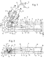
- eine schematische teilweise geschnittene Seitenansicht eines erfindungsgemäßen Gurtstraffers, welcher an einem Fahrzeugchassis angebracht ist, und
- Fig. 2
- eine schematische Schnittansicht nach Linie II-II in Fig. 1.
- Fig. 1
- is a schematic partially sectioned side view of a belt tensioner according to the invention, which is attached to a vehicle chassis, and
- Fig. 2
- 2 shows a schematic sectional view along line II-II in FIG. 1.
Nach der Zeichnung ist eine horizontal am Fahrzeugchassis 12 angeordnete Antriebsvorrichtung 11 als pyrotechnisch arbeitende Kolben(25)-Zylinder(26)-Einheit ausgebildet, deren hinterer Zylinderraum 27 am vom Kolben 25 abgewandten Ende eine zur Atmosphäre führende Öffnung 28 aufweist, während der vor dem Kolben 25 befindliche Zylinderraum 29 mit einer pyrotechnischen Druckerzeugungsvorrichtung 30 verbunden ist, die über eine Steckbuchse 31 an einen nicht dargestellen Beschleunigungssensor anschließbar ist. Im Falle einer unfallbedingten Beschleunigung bewirkt der bei 31 angeschlossene Sensor eine Zündung der in der pyrotechnischen Druckerzeugungsvorrichtung 30 befindlichen Ladung 32, wodurch im Zylinderraum 29 schlagartig ein hoher Druck aufgebaut wird, der den Kolben 25 in Richtung des Pfeiles F nach hinten verschiebt.According to the drawing, a horizontally arranged on the
Mit dem Zentrum des Kolbens 25 fest verbunden ist ein als Drahtseil ausgebildetes flexibles Zugelement 13, welches durch eine dichte Bohrung 33 am vorderen Ende des Zylinders 26 hindurchtritt und dann durch einen geraden Kanal 34 hindurchgeführt ist, in dessen Bereich rundum das Drahtseil 13 eine nur schematisch angedeutete Rückzugssperre 35 angeordnet ist.Fixed to the center of the
Bei 36 tritt das Drahtseil 13 aus der Antriebsvorrichtung 11 aus und erstreckt sich geradlinig zum Umfang eines Umlenkgliedes 14, welches unten einen mit Außengewinde versehenen Bolzenabschnitt 14', darüber einen Umlenkabschnitt 14'' größeren Durchmessers und ganz oben einen einen noch größeren Durchmesser aufweisenden Kopf-Führungsabschnitt 14'''' aufweist.At 36, the
Vom vorderen Ende der Antriebsvorrichtung 11 erstreckt sich einstückig ein plattenartiger Fortsatz 20 bis über das Umlenkglied 14 hinaus. Er ist bei 37 nach oben abgerundet und geht dort in eine schräg nach oben weisende Abwinklung 21, die ebenfalls plattenartig ausgebildet sein kann, über.A plate-
Wie insbesondere aus Fig. 2 hervorgeht, weist der Fortsatz 20 im Bereich einer im Fahrzeugchassis 12 vorgesehenen Gewindebohrung 18 eine durchgehende Bohrung 19 etwas größeren Durchmessers auf, durch die hindurch der Bolzenabschnitt 14' des Umlenkgliedes 14 in die Gewindebohrung 18 eingeschraubt ist. Dabei legt sich die zwischen dem Bolzenabschnitt 14' und dem Umlenkabschnitt 14'' befindliche horizontale Ringstufe 14''' auf die Oberfläche des Fortsatzes 20 rings um die durchgehende Bohrung 19 auf und drückt somit den Fortsatz 20 gegen das Fahrzeugchassis 12, so daß der Fortsatz 20 einschließlich der mit ihm einstückigen Antriebsvorrichtung 11 und der Abwinklung 21 sicher am Fahrzeugchassis 12 befestigt sind. Statt des Bolzenabschnitts 14' könnte auch ein mit Innengewinde versehener, nach unten offener Hülsenabschnitt vorgesehen sein, der auf einen am Fahrzeugchassis 12 befestigten, z.B. angeschweißten Gewindebolzen aufgeschraubt ist, wodurch ebenfalls der Fortsatz 20 an das Chassis 12 gepreßt werden kann.As can be seen in particular from FIG. 2, the
Das Drahtseil 13 weist einen Hinführteil 13'' auf, der nach Fig. 2 um den oberen Bereich des Umlenkabschnittes 14'' herumgeführt ist, bis er die aus Fig. 1 ersichtliche Richtung zum Gurtschloßteil 15 hin erreicht hat. Der Hinführteil 13'' erstreckt sich dann innerhalb der entsprechend hohl ausgebildeten Abwinklung 21 bis zum Gurtschloßteil 15, an dem sich eine Umlenkrolle 23 befindet, um die das Drahtseil 13 um ca. 180° herumgeführt ist. Das dadurch gebildete Rückführteil 13' des Drahtseiles 13 wird dann um ein fest an der Abwinklung 21 angeordnetes Umlenkteil 38 so herumgelenkt, daß es zum vorderen Bereich des Umlenkabschnitts 14'' gelangt, wo es unterhalb des Hinführteils 13'' in ähnlicher Weise wie dieses um den Umlenkabschnitt 14'' herumgelegt ist. Während das Hinführteil 13'' den Umlenkabschnitt 14'' über einen Winkel von etwas mehr als 90° umschlingt, beträgt der Umschlingungswinkel des Rückführteils 13' etwas mehr als 180°. Das freie Ende 13''' des Rückführteils 13' ist mit einem Befestigungskopf 24 versehen, mittels dessen es an einem Anschlagkragen 39 des Fortsatzes 20 bzw. der Abwinklung 21 gegen eine Bewegung in Richtung des Pfeiles f gesichert ist.The
Oberhalb des Gurtschloßteils 15, dessen technische Einzelheiten im einzelnen nicht dargestellt sind, ist in verkleinerter Wiedergabe das mit ihm zusammenarbeitende Schloß-Gegenstück 17 angedeutet, von dem sich die beiden Teile 16 eines Dreipunktgurtes 16 zu oberen bzw. unteren Bereichen des Fahrzeugchassis 12 erstrecken, wo sie in bekannter Weise befestigt sind.Above the
Die Funktion des beschriebenen Gurtstraffers ist wie folgt:
Der Gurtstraffer wird im Herstellerbetrieb so zusammengebaut, daß die Antriebsvorrichtung 11, der Fortsatz 20, die Abwinklung 21, die Federmanschette 22 und das Gurtschloßteil 15 eine Baueinheit bilden, in der das Zugseil 13 in der aus der Zeichnung ersichtlichen Form angeordnet und fixiert ist. Vorzugsweise ist auch das Umlenkglied 14 bereits in die durchgehende Bohrung 19 eingesteckt und beispielsweise durch einen in Fig. 2 von unten aufgesteckten Federring gegen Herausfallen aus der Bohrung 19 gesichert. In dieser Form wird der Gurtstraffer beim Automobilhersteller angeliefert.The function of the belt tensioner described is as follows:
The belt tensioner is assembled in manufacturing operation so that the
Dieser muß im Fahrzeugchassis 12 an der vorgesehenen Stelle lediglich die Gewindebohrung 18 vorsehen und - gegebenenfalls nach Entfernen des vorerwähnten Federringes - das Umlenkglied 14 mittels des Bolzenabschnittes 14' in die Gewindebohrung 18 einschrauben, bis die Ringstufe 14''' den Fortsatz 20 fest an das Fahrzeugchassis 12 angedrückt hat.This must only provide the threaded
Nunmehr ist der Gurtstraffer so am Fahrzeugchassis 12 festgelegt, daß die bei einer Auslösung der pyrotechnischen Druckerzeugungsvorrichtung 30 auftretenden Umlenkkräfte am Umlenkglied 14 nicht erst auf den es umgebenden Fortsatz 20, sondern unmittelbar über den Bolzenabschnitt 14' in das Fahrzeugchassis 12 eingeleitet werden. Um ein Verdrehen der Anordnung um die Achse des Umlenkgliedes 14 zu vermeiden, können unmittelbar neben dem hinteren Ende der Antriebsvorrichtung 11 am Fahrzeugchassis 12 Vorsprünge 40 vorgesehen sein, zwischen die bei der Montage das hintere Ende der Antriebsvorrichtung 11 in der aus Fig. 1 und 2 ersichtlichen Weise eingeführt wird, bevor das Umlenkglied 14 festgeschraubt wird.The belt tensioner is now fixed on the
Nach der Montage wird an die Buchse 31 der nicht dargestellte Beschleunigungssensor angeschlossen. Tritt jetzt eine unfallbedingte Beschleunigung auf, so zündet der Sensor die pyrotechnische Ladung 32, und es wird im Zylinderraum 29 schlagartig ein hoher Druck erzeugt, der den Kolben 25 in Richtung des Pfeiles F beschleunigt. Dadurch wird das Drahtseil 13 nach rechts verschoben, wobei die Umlenkrolle 23 des Gurtschloßteils 15 nach unten gezogen wird. Hierbei wird die in Fig. 1 stark verkürzt dargestellte Federmanschette 22 axial zusammengedrückt. Die Folge ist eine Straffung der Gurte 16, sofern der Gurt durch Einführen des Gegenstückes 17 in das Gurtschloßteil 15 zuvor geschlossen worden war.After assembly, the acceleration sensor, not shown, is connected to the
Sobald der Kolben 25 das hintere Ende des Zylinders 26 erreicht hat und sich das Gurtschloßteil 15 in der am weitesten nach unten verschobenen Position befindet, wird die von den Gurten 16 gesicherte Person nach vorn in den Gurt fallen und eine erhebliche Zugkraft in Richtung der Pfeile P in Fig. 1 auf das Gurtschloßteil 15 ausüben. Dieses versucht daraufhin über die Umlenkrolle 23 das Hinführteil 13'' des Drahtseils 13 wieder auszuziehen, wobei dann jedoch die Rückzugssperre 35 wirksam wird und ein Wieder-Ausziehen des Drahtseils 13 wirksam verhindert. Auch die hierbei auftretenden erheblichen Umlenkkräfte werden vom direkt in das Chassis 12 eingeschraubten Umlenkglied 14 unmittelbar auf das Fahrzeugchassis 12 übertragen. Das Umlenkglied 14 gibt auch die vom Rückführteil 13' ausgeübten, im wesentlichen gleich großen Umlenkkräfte unmittelbar an das Fahrzeugchassis 12 weiter.As soon as the
Das hierbei wegen des radialen Abstandes des um den Umlenkabschnitt 14'' herumgeführten Drahtseilteiles von dem Mittelpunkt des Umlenkgliedes 14 auftretende geringfügige Drehmoment wird ohne weiteres durch die hierfür besonders zweckmäßigen Vorsprünge 40 am Ende der Antriebsvorrichtung 11 aufgefangen. Die wesentlichen Kräfte werden also jeweils vom Drahtseil 13 über das Umlenkglied 14 unmittelbar auf das Chassis 12 übertragen.The slight torque occurring here due to the radial distance of the wire rope part guided around the
Auf dem Umfangsabschnitt 14'' kann auch eine drehbare Seilrolle zur reibungsarmen Umlenkung des um die Seilrolle herumgeführten Drahtseiles 13 vorgesehen sein, welche aber nichts an der unmittelbaren Übertragung der Umlenkkräfte über das Umlenkglied 14 auf das Fahrzeugchassis 12 ändert. In jedem Fall müssen der Fortsatz 20 und die Abwinklung 21 keine Umlenkkräfte aufnehmen.A rotatable cable pulley can also be provided on the
Claims (13)
dadurch gekennzeichnet,
daß das Umlenkglied (14) gleichzeitig als die Antriebsvorrichtung (11) am Fahrzeugchassis (12) festlegendes Befestigungselement ausgebildet ist, welches unmittelbar mit dem Fahrzeugchassis (12) fest verbindbar ist.Seat belt tensioners for motor vehicles which can be fastened to the vehicle chassis (12) and have an elongated drive device (11) which can be arranged essentially horizontally in the motor vehicle, a flexible tension element (13) which can be displaced in its longitudinal direction by the drive device (11) and which is driven by the drive device (11) deflection member (14) attached to the vehicle chassis (12) is guided upwards to a belt buckle part (15) which cooperates with a counterpart (17) arranged at the end of a three-point or lap belt (16) and is attached there to transmit a tensile force,
characterized,
that the deflecting member (14) is at the same time designed as a fastening element which fixes the drive device (11) on the vehicle chassis (12) and which can be directly connected to the vehicle chassis (12).
dadurch gekennzeichnet,
daß sich von der Antriebsvorrichtung (11), wo das Zugelement (13) austritt, ein Fortsatz (20) bis in den Bereich des unmittelbar am Fahrzeugchassis (12) befestigbaren Umlenkgliedes (14) erstreckt, und daß der Fortsatz (20) eine nach oben gerichtete Abwinklung (21) aufweist, an der über eine Federmanschette (22) der Gurtschloßteil (15) elastisch und relativ zur Abwinklung (21) federnd zurückziehbar angeordnet ist.Seat belt tensioners for motor vehicles which can be fastened to the vehicle chassis (12) and have an elongated drive device (11) which can be arranged essentially horizontally in the motor vehicle, a flexible tension element (13) which can be displaced in its longitudinal direction by the drive device (11) and which is driven by the drive device (11) deflection member (14) attached to the vehicle chassis (12) is guided upwards to a belt buckle part (15) which cooperates with a counterpart (17) arranged at the end of a three-point or lap belt (16) and is attached there to transmit a tensile force, in particular according to one of the claims 1 to 6,
characterized,
that an extension (20) extends from the drive device (11), where the pulling element (13) exits, into the region of the deflection member (14) which can be fastened directly to the vehicle chassis (12), and that the extension (20) extends upwards has directed angled portion (21), on which, via a spring collar (22), the belt buckle part (15) is arranged to be resilient and retractable relative to the angled portion (21).
daß ein Rückführteil (13') des Zuggliedes (13) über ein am Gurtschloßteil (15) befestigtes Umlenkelement (23) zur Antriebsvorrichtung (11) bzw. einem daran befestigten Fortsatz (20) oder einer vom Fortsatz (20) ausgehenden Abwinklung (21) zurückgeführt und mit seinem freien Ende (13'') dort befestigt ist.Seat belt tensioners for motor vehicles which can be fastened to the vehicle chassis (12) and have an elongated drive device (11) which can be arranged essentially horizontally in the motor vehicle, a flexible tension element (13) which can be displaced in its longitudinal direction by the drive device (11) and which is driven by the drive device (11) deflection member (14) attached to the vehicle chassis (12) is guided upward to a belt buckle part (15) which cooperates with a counterpart (17) arranged at the end of a three-point or lap belt (16) and is attached there to transmit a tensile force, in particular according to one of the preceding ones Claims, characterized,
that a return part (13 ') of the tension member (13) via a deflection element (23) attached to the belt buckle part (15) to the drive device (11) or an extension (20) attached thereto or an angled portion (21) extending from the extension (20) returned and fixed there with its free end (13 '').
daß das Rückführteil (13') des Zugelementes (13) bis zum Umlenkglied (14) geführt, vorzugsweise auf der gleichen Seite wie das Hinführteil (13'') des Zugelementes (13) zumindest teilweise und vorzugsweise um etwa 180° um den entsprechend hoch ausgebildeten Umlenkabschnitt (14'') herumgelegt und erst danach mit seinem freien Ende (13'') am Fortsatz (20) oder der Abwinklung (21) festgelegt ist.Belt tensioner according to claim 8, characterized in that
that the return part (13 ') of the tension element (13) is guided up to the deflection member (14), preferably on the same side as the feed part (13'') of the tension element (13) at least partially and preferably by approximately 180 ° around the correspondingly high trained deflection section (14 '') laid around and only then with its free end (13 '') on the extension (20) or the bend (21) is fixed.
Applications Claiming Priority (2)
| Application Number | Priority Date | Filing Date | Title |
|---|---|---|---|
| DE4422022A DE4422022A1 (en) | 1994-06-23 | 1994-06-23 | Seat belt tensioners for motor vehicles |
| DE4422022 | 1994-06-23 |
Publications (2)
| Publication Number | Publication Date |
|---|---|
| EP0689972A1 true EP0689972A1 (en) | 1996-01-03 |
| EP0689972B1 EP0689972B1 (en) | 1998-09-09 |
Family
ID=6521345
Family Applications (1)
| Application Number | Title | Priority Date | Filing Date |
|---|---|---|---|
| EP95108904A Expired - Lifetime EP0689972B1 (en) | 1994-06-23 | 1995-06-09 | Seatbelt pretensionner for vehicles |
Country Status (4)
| Country | Link |
|---|---|
| US (1) | US5588677A (en) |
| EP (1) | EP0689972B1 (en) |
| AT (1) | ATE170807T1 (en) |
| DE (2) | DE4422022A1 (en) |
Families Citing this family (24)
| Publication number | Priority date | Publication date | Assignee | Title |
|---|---|---|---|---|
| US5704638A (en) * | 1995-12-18 | 1998-01-06 | Alliedsignal Inc. | Integrated side impact inflator and module with seat belt pretensioning capability |
| DE29605818U1 (en) * | 1996-03-28 | 1996-07-25 | Trw Repa Gmbh | Vehicle occupant restraint system with a belt tensioner |
| US6089605A (en) * | 1996-10-07 | 2000-07-18 | Inova Gmbh Technische Entwicklungen | Device for tightening a seat belt in a motor vehicle |
| DE29702125U1 (en) * | 1997-02-07 | 1997-06-05 | Trw Repa Gmbh | Vehicle occupant restraint system |
| US5944350A (en) * | 1997-11-14 | 1999-08-31 | Takata Inc. | Buckle pretensioner |
| WO1999058377A1 (en) * | 1998-05-08 | 1999-11-18 | Breed Automotive Technology, Inc. | Pretensioner |
| US6076856A (en) * | 1999-01-12 | 2000-06-20 | General Motors Corporation | Belt tension and energy absorbing apparatus |
| GB2351948B (en) * | 1999-07-14 | 2001-10-31 | Breed Automotive Tech | Pretensioner locking mechanism |
| DE10033566B4 (en) * | 1999-07-14 | 2005-08-18 | Key Safety Systems, Inc., Sterling Heights | belt tensioner |
| US6264281B1 (en) * | 1999-08-25 | 2001-07-24 | Daimlerchrysler Corporation | Seat belt buckle pretensioner mounting mechanism |
| DE19960848B4 (en) | 1999-12-16 | 2005-07-07 | Key Safety Systems, Inc., Sterling Heights | Device for tightening a safety belt |
| DE10105500B4 (en) * | 2001-02-07 | 2004-02-05 | Breed Automotive Technology, Inc., Lakeland | Device for tightening a three-point seat belt arranged in a vehicle rear |
| JP2003054360A (en) * | 2001-06-06 | 2003-02-26 | Takata Corp | Seat belt device |
| DE10135218A1 (en) * | 2001-07-24 | 2003-02-06 | Bosch Gmbh Robert | Motor vehicle lock |
| DE50303917D1 (en) * | 2002-09-04 | 2006-08-03 | Takata Petri Gmbh Ulm | belt buckle tensioners |
| US7303209B2 (en) * | 2005-03-29 | 2007-12-04 | Ming Yat Kwok | Transportation riders web restrain system |
| US7380832B2 (en) * | 2005-04-05 | 2008-06-03 | Takata Seat Belts, Inc. | Pretensioner with integrated gas generator |
| US7862081B2 (en) * | 2008-10-09 | 2011-01-04 | Gm Global Technology Operations, Inc. | Motor vehicle safety restraint system |
| DE102008057124B4 (en) * | 2008-11-13 | 2023-03-16 | Volkswagen Ag | Safety belt arrangement in motor vehicles |
| US7905514B2 (en) * | 2008-11-14 | 2011-03-15 | GM Global Technology Operations LLC | Motor vehicle safety restraint system |
| DE102009005205A1 (en) * | 2009-01-20 | 2010-07-22 | Trw Automotive Gmbh | Vehicle part-adjustment |
| KR101326489B1 (en) * | 2012-08-30 | 2013-11-08 | 현대자동차주식회사 | Anchor pre-tensioner for safety seat belt |
| DE102012023778A1 (en) * | 2012-12-05 | 2014-06-05 | GM Global Technology Operations LLC (n. d. Ges. d. Staates Delaware) | Seat belt webbing for placement on a vehicle seat of a motor vehicle |
| DE102017101807A1 (en) * | 2016-12-16 | 2018-06-21 | Trw Automotive Gmbh | force limiters |
Citations (11)
| Publication number | Priority date | Publication date | Assignee | Title |
|---|---|---|---|---|
| FR2180151A5 (en) | 1972-04-10 | 1973-11-23 | Peugeot & Renault | |
| DE2543068A1 (en) | 1974-10-03 | 1976-04-08 | Foerenade Fabriksverken | ARRANGEMENT FOR TENSIONING A SEAT BELT |
| DE8437589U1 (en) * | 1984-12-21 | 1986-07-03 | Autoflug GmbH & Co Fahrzeugtechnik, 2084 Rellingen | Rear seat belt for motor vehicles |
| EP0186880A2 (en) * | 1984-12-21 | 1986-07-09 | Autoflug Gmbh & Co Fahrzeugtechnik | Tightening device for a back seat safety belt in vehicles |
| EP0306299A1 (en) * | 1987-09-03 | 1989-03-08 | Bsrd Limited | Tensioning device |
| EP0415418A2 (en) * | 1989-09-01 | 1991-03-06 | TRW Occupant Restraint Systems GmbH | Buckle for a safety belt system provided with a tensioning device |
| EP0502370A1 (en) * | 1991-02-27 | 1992-09-09 | FUJI KIKO CO., Ltd. | Safety belt system with emergency retraction capability |
| EP0567303A1 (en) * | 1992-04-23 | 1993-10-27 | Alliedsignal Limited | Safety restraint pretensioning |
| EP0577073A1 (en) * | 1992-06-30 | 1994-01-05 | TAKATA (EUROPE) VEHICLE, SAFETY TECHNOLOGY GmbH | Process for locking the release button, respectively locking mechanism of a seat belt buckle in vehicles and seat belt system using this process |
| DE4230665A1 (en) | 1992-09-14 | 1994-03-17 | Takata Europ Gmbh | Seat belt assembly for vehicles |
| DE9408983U1 (en) * | 1994-06-01 | 1994-09-29 | Hs Tech & Design | Pyrotechnic belt tensioner |
Family Cites Families (10)
| Publication number | Priority date | Publication date | Assignee | Title |
|---|---|---|---|---|
| FR1574856A (en) * | 1968-05-02 | 1969-07-18 | ||
| SE455184B (en) * | 1985-10-25 | 1988-06-27 | Autoliv Dev | EMERGENCY LOADING DEVICE FOR A EXTRAORDINABLE TIRE IN A VEHICLE SEED BELT |
| US4913497A (en) * | 1987-07-21 | 1990-04-03 | Britax-Kolb Gmbh & Co. | Belt tightener for seat belts in vehicles |
| EP0450914A1 (en) * | 1990-04-03 | 1991-10-09 | Bsrd Limited | Pretensioning latching mechanism |
| JPH045148A (en) * | 1990-04-23 | 1992-01-09 | Takata Kk | Buckle pretensioner |
| DE59102362D1 (en) * | 1991-02-20 | 1994-09-01 | Trw Repa Gmbh | Rear tensioning device in a seat belt system for vehicles. |
| DE9112121U1 (en) * | 1991-09-28 | 1991-12-19 | Adam Opel Ag, 6090 Ruesselsheim, De | |
| DE4136623A1 (en) * | 1991-11-07 | 1993-05-13 | Trw Repa Gmbh | BELT TENSIONERS FOR VEHICLE SAFETY BELT SYSTEMS |
| DE4215563A1 (en) * | 1992-05-12 | 1993-11-18 | Trw Repa Gmbh | Lock for vehicle seat belt systems |
| DE4230663A1 (en) * | 1992-09-14 | 1994-03-17 | Takata Europ Gmbh | Method and device for tightening seat belts |
-
1994
- 1994-06-23 DE DE4422022A patent/DE4422022A1/en not_active Withdrawn
-
1995
- 1995-06-09 EP EP95108904A patent/EP0689972B1/en not_active Expired - Lifetime
- 1995-06-09 AT AT95108904T patent/ATE170807T1/en not_active IP Right Cessation
- 1995-06-09 DE DE59503504T patent/DE59503504D1/en not_active Expired - Fee Related
- 1995-06-19 US US08/492,286 patent/US5588677A/en not_active Expired - Lifetime
Patent Citations (12)
| Publication number | Priority date | Publication date | Assignee | Title |
|---|---|---|---|---|
| FR2180151A5 (en) | 1972-04-10 | 1973-11-23 | Peugeot & Renault | |
| DE2543068A1 (en) | 1974-10-03 | 1976-04-08 | Foerenade Fabriksverken | ARRANGEMENT FOR TENSIONING A SEAT BELT |
| DE8437589U1 (en) * | 1984-12-21 | 1986-07-03 | Autoflug GmbH & Co Fahrzeugtechnik, 2084 Rellingen | Rear seat belt for motor vehicles |
| EP0186880A2 (en) * | 1984-12-21 | 1986-07-09 | Autoflug Gmbh & Co Fahrzeugtechnik | Tightening device for a back seat safety belt in vehicles |
| EP0186880B1 (en) | 1984-12-21 | 1990-06-20 | Autoflug Gmbh & Co Fahrzeugtechnik | Tightening device for a back seat safety belt in vehicles |
| EP0306299A1 (en) * | 1987-09-03 | 1989-03-08 | Bsrd Limited | Tensioning device |
| EP0415418A2 (en) * | 1989-09-01 | 1991-03-06 | TRW Occupant Restraint Systems GmbH | Buckle for a safety belt system provided with a tensioning device |
| EP0502370A1 (en) * | 1991-02-27 | 1992-09-09 | FUJI KIKO CO., Ltd. | Safety belt system with emergency retraction capability |
| EP0567303A1 (en) * | 1992-04-23 | 1993-10-27 | Alliedsignal Limited | Safety restraint pretensioning |
| EP0577073A1 (en) * | 1992-06-30 | 1994-01-05 | TAKATA (EUROPE) VEHICLE, SAFETY TECHNOLOGY GmbH | Process for locking the release button, respectively locking mechanism of a seat belt buckle in vehicles and seat belt system using this process |
| DE4230665A1 (en) | 1992-09-14 | 1994-03-17 | Takata Europ Gmbh | Seat belt assembly for vehicles |
| DE9408983U1 (en) * | 1994-06-01 | 1994-09-29 | Hs Tech & Design | Pyrotechnic belt tensioner |
Also Published As
| Publication number | Publication date |
|---|---|
| ATE170807T1 (en) | 1998-09-15 |
| US5588677A (en) | 1996-12-31 |
| EP0689972B1 (en) | 1998-09-09 |
| DE4422022A1 (en) | 1996-01-04 |
| DE59503504D1 (en) | 1998-10-15 |
Similar Documents
| Publication | Publication Date | Title |
|---|---|---|
| EP0689972B1 (en) | Seatbelt pretensionner for vehicles | |
| DE102006053563B4 (en) | Belt tensioner for a safety belt system | |
| WO2003082640A1 (en) | High performance tightener | |
| WO2012065654A1 (en) | Seatbelt tensioner with a force-limiting device, and method thereof | |
| DE10105500B4 (en) | Device for tightening a three-point seat belt arranged in a vehicle rear | |
| WO2006128615A2 (en) | Child seat for vehicles | |
| DE202006004748U1 (en) | Belt tensioner for a safety belt system | |
| DE3044951C2 (en) | Back tensioner for a seat belt | |
| EP0148747A2 (en) | Safety belt system | |
| EP1369318A1 (en) | Device for tensioning a seat belt | |
| DE2726096C2 (en) | ||
| DE10119199B4 (en) | pretensioners | |
| EP4211004A1 (en) | Belt retractor | |
| DE102016224599B4 (en) | Seat belt pretensioner and seat belt assembly having one | |
| DE2304878C2 (en) | Safety belt assembly for vehicles, in particular for motor vehicles | |
| WO2020178413A1 (en) | End fitting tensioner for a seat belt assembly of a vehicle | |
| DE102007033154B4 (en) | Safety belt system for a motor vehicle | |
| EP0588262A1 (en) | Method and means for the tightening of seat belts | |
| DE3432451A1 (en) | SAFETY BELT ARRANGEMENT | |
| DE3727666A1 (en) | Pyrotechnical drive device for the tightening devices of safety belts | |
| EP0778182A2 (en) | Vehicle restraint system | |
| DE19957794C2 (en) | Seat belt arrangement in vehicles | |
| DE10239437B4 (en) | seat belt system | |
| EP0635407B1 (en) | Vehicle safety belt device with pretensioner | |
| EP0480137B1 (en) | Pre-tensioner for a three-point safety belt system for vehicles |
Legal Events
| Date | Code | Title | Description |
|---|---|---|---|
| PUAI | Public reference made under article 153(3) epc to a published international application that has entered the european phase |
Free format text: ORIGINAL CODE: 0009012 |
|
| AK | Designated contracting states |
Kind code of ref document: A1 Designated state(s): AT DE ES FR GB IT SE |
|
| 17P | Request for examination filed |
Effective date: 19960209 |
|
| 17Q | First examination report despatched |
Effective date: 19970131 |
|
| GRAG | Despatch of communication of intention to grant |
Free format text: ORIGINAL CODE: EPIDOS AGRA |
|
| GRAG | Despatch of communication of intention to grant |
Free format text: ORIGINAL CODE: EPIDOS AGRA |
|
| GRAH | Despatch of communication of intention to grant a patent |
Free format text: ORIGINAL CODE: EPIDOS IGRA |
|
| GRAH | Despatch of communication of intention to grant a patent |
Free format text: ORIGINAL CODE: EPIDOS IGRA |
|
| GRAA | (expected) grant |
Free format text: ORIGINAL CODE: 0009210 |
|
| AK | Designated contracting states |
Kind code of ref document: B1 Designated state(s): AT DE ES FR GB IT SE |
|
| PG25 | Lapsed in a contracting state [announced via postgrant information from national office to epo] |
Ref country code: IT Free format text: LAPSE BECAUSE OF FAILURE TO SUBMIT A TRANSLATION OF THE DESCRIPTION OR TO PAY THE FEE WITHIN THE PRESCRIBED TIME-LIMIT;WARNING: LAPSES OF ITALIAN PATENTS WITH EFFECTIVE DATE BEFORE 2007 MAY HAVE OCCURRED AT ANY TIME BEFORE 2007. THE CORRECT EFFECTIVE DATE MAY BE DIFFERENT FROM THE ONE RECORDED. Effective date: 19980909 Ref country code: FR Free format text: LAPSE BECAUSE OF FAILURE TO SUBMIT A TRANSLATION OF THE DESCRIPTION OR TO PAY THE FEE WITHIN THE PRESCRIBED TIME-LIMIT Effective date: 19980909 Ref country code: ES Free format text: THE PATENT HAS BEEN ANNULLED BY A DECISION OF A NATIONAL AUTHORITY Effective date: 19980909 |
|
| REF | Corresponds to: |
Ref document number: 170807 Country of ref document: AT Date of ref document: 19980915 Kind code of ref document: T |
|
| REF | Corresponds to: |
Ref document number: 59503504 Country of ref document: DE Date of ref document: 19981015 |
|
| GBT | Gb: translation of ep patent filed (gb section 77(6)(a)/1977) |
Effective date: 19981105 |
|
| PG25 | Lapsed in a contracting state [announced via postgrant information from national office to epo] |
Ref country code: SE Free format text: LAPSE BECAUSE OF FAILURE TO SUBMIT A TRANSLATION OF THE DESCRIPTION OR TO PAY THE FEE WITHIN THE PRESCRIBED TIME-LIMIT Effective date: 19981209 |
|
| EN | Fr: translation not filed | ||
| PG25 | Lapsed in a contracting state [announced via postgrant information from national office to epo] |
Ref country code: AT Free format text: LAPSE BECAUSE OF NON-PAYMENT OF DUE FEES Effective date: 19990609 |
|
| PLBE | No opposition filed within time limit |
Free format text: ORIGINAL CODE: 0009261 |
|
| STAA | Information on the status of an ep patent application or granted ep patent |
Free format text: STATUS: NO OPPOSITION FILED WITHIN TIME LIMIT |
|
| 26N | No opposition filed | ||
| REG | Reference to a national code |
Ref country code: GB Ref legal event code: IF02 |
|
| PGFP | Annual fee paid to national office [announced via postgrant information from national office to epo] |
Ref country code: GB Payment date: 20090603 Year of fee payment: 15 Ref country code: DE Payment date: 20090604 Year of fee payment: 15 |
|
| GBPC | Gb: european patent ceased through non-payment of renewal fee |
Effective date: 20100609 |
|
| PG25 | Lapsed in a contracting state [announced via postgrant information from national office to epo] |
Ref country code: DE Free format text: LAPSE BECAUSE OF NON-PAYMENT OF DUE FEES Effective date: 20110101 |
|
| PG25 | Lapsed in a contracting state [announced via postgrant information from national office to epo] |
Ref country code: GB Free format text: LAPSE BECAUSE OF NON-PAYMENT OF DUE FEES Effective date: 20100609 |