EP0689364A2 - Recording and reproducing digital video signals - Google Patents
Recording and reproducing digital video signals Download PDFInfo
- Publication number
- EP0689364A2 EP0689364A2 EP95304378A EP95304378A EP0689364A2 EP 0689364 A2 EP0689364 A2 EP 0689364A2 EP 95304378 A EP95304378 A EP 95304378A EP 95304378 A EP95304378 A EP 95304378A EP 0689364 A2 EP0689364 A2 EP 0689364A2
- Authority
- EP
- European Patent Office
- Prior art keywords
- data
- area
- recording
- variable
- track
- Prior art date
- Legal status (The legal status is an assumption and is not a legal conclusion. Google has not performed a legal analysis and makes no representation as to the accuracy of the status listed.)
- Granted
Links
Images


Classifications
-
- H—ELECTRICITY
- H04—ELECTRIC COMMUNICATION TECHNIQUE
- H04N—PICTORIAL COMMUNICATION, e.g. TELEVISION
- H04N21/00—Selective content distribution, e.g. interactive television or video on demand [VOD]
- H04N21/20—Servers specifically adapted for the distribution of content, e.g. VOD servers; Operations thereof
- H04N21/23—Processing of content or additional data; Elementary server operations; Server middleware
- H04N21/236—Assembling of a multiplex stream, e.g. transport stream, by combining a video stream with other content or additional data, e.g. inserting a URL [Uniform Resource Locator] into a video stream, multiplexing software data into a video stream; Remultiplexing of multiplex streams; Insertion of stuffing bits into the multiplex stream, e.g. to obtain a constant bit-rate; Assembling of a packetised elementary stream
-
- G—PHYSICS
- G06—COMPUTING; CALCULATING OR COUNTING
- G06T—IMAGE DATA PROCESSING OR GENERATION, IN GENERAL
- G06T9/00—Image coding
- G06T9/007—Transform coding, e.g. discrete cosine transform
-
- H—ELECTRICITY
- H04—ELECTRIC COMMUNICATION TECHNIQUE
- H04N—PICTORIAL COMMUNICATION, e.g. TELEVISION
- H04N21/00—Selective content distribution, e.g. interactive television or video on demand [VOD]
- H04N21/40—Client devices specifically adapted for the reception of or interaction with content, e.g. set-top-box [STB]; Operations thereof
- H04N21/43—Processing of content or additional data, e.g. demultiplexing additional data from a digital video stream; Elementary client operations, e.g. monitoring of home network or synchronising decoder's clock; Client middleware
- H04N21/434—Disassembling of a multiplex stream, e.g. demultiplexing audio and video streams, extraction of additional data from a video stream; Remultiplexing of multiplex streams; Extraction or processing of SI; Disassembling of packetised elementary stream
-
- H—ELECTRICITY
- H04—ELECTRIC COMMUNICATION TECHNIQUE
- H04N—PICTORIAL COMMUNICATION, e.g. TELEVISION
- H04N9/00—Details of colour television systems
- H04N9/79—Processing of colour television signals in connection with recording
- H04N9/80—Transformation of the television signal for recording, e.g. modulation, frequency changing; Inverse transformation for playback
- H04N9/804—Transformation of the television signal for recording, e.g. modulation, frequency changing; Inverse transformation for playback involving pulse code modulation of the colour picture signal components
- H04N9/8042—Transformation of the television signal for recording, e.g. modulation, frequency changing; Inverse transformation for playback involving pulse code modulation of the colour picture signal components involving data reduction
-
- H—ELECTRICITY
- H04—ELECTRIC COMMUNICATION TECHNIQUE
- H04N—PICTORIAL COMMUNICATION, e.g. TELEVISION
- H04N5/00—Details of television systems
- H04N5/76—Television signal recording
- H04N5/78—Television signal recording using magnetic recording
- H04N5/782—Television signal recording using magnetic recording on tape
- H04N5/7824—Television signal recording using magnetic recording on tape with rotating magnetic heads
- H04N5/7826—Television signal recording using magnetic recording on tape with rotating magnetic heads involving helical scanning of the magnetic tape
- H04N5/78263—Television signal recording using magnetic recording on tape with rotating magnetic heads involving helical scanning of the magnetic tape for recording on tracks inclined relative to the direction of movement of the tape
- H04N5/78266—Television signal recording using magnetic recording on tape with rotating magnetic heads involving helical scanning of the magnetic tape for recording on tracks inclined relative to the direction of movement of the tape using more than one track for the recording of one television field or frame, i.e. segmented recording
-
- H—ELECTRICITY
- H04—ELECTRIC COMMUNICATION TECHNIQUE
- H04N—PICTORIAL COMMUNICATION, e.g. TELEVISION
- H04N5/00—Details of television systems
- H04N5/76—Television signal recording
- H04N5/78—Television signal recording using magnetic recording
- H04N5/782—Television signal recording using magnetic recording on tape
- H04N5/783—Adaptations for reproducing at a rate different from the recording rate
-
- H—ELECTRICITY
- H04—ELECTRIC COMMUNICATION TECHNIQUE
- H04N—PICTORIAL COMMUNICATION, e.g. TELEVISION
- H04N9/00—Details of colour television systems
- H04N9/79—Processing of colour television signals in connection with recording
- H04N9/80—Transformation of the television signal for recording, e.g. modulation, frequency changing; Inverse transformation for playback
- H04N9/82—Transformation of the television signal for recording, e.g. modulation, frequency changing; Inverse transformation for playback the individual colour picture signal components being recorded simultaneously only
- H04N9/8205—Transformation of the television signal for recording, e.g. modulation, frequency changing; Inverse transformation for playback the individual colour picture signal components being recorded simultaneously only involving the multiplexing of an additional signal and the colour video signal
- H04N9/8227—Transformation of the television signal for recording, e.g. modulation, frequency changing; Inverse transformation for playback the individual colour picture signal components being recorded simultaneously only involving the multiplexing of an additional signal and the colour video signal the additional signal being at least another television signal
Landscapes
- Engineering & Computer Science (AREA)
- Multimedia (AREA)
- Signal Processing (AREA)
- Physics & Mathematics (AREA)
- General Physics & Mathematics (AREA)
- Discrete Mathematics (AREA)
- Theoretical Computer Science (AREA)
- Television Signal Processing For Recording (AREA)
- Signal Processing For Digital Recording And Reproducing (AREA)
- Holo Graphy (AREA)
- Signal Processing Not Specific To The Method Of Recording And Reproducing (AREA)
Abstract
Each track is divided into a first area and a second area. The input data are directly recorded in the first area, and sequential variable-speed playback data is recorded in the second area of each track. These variable-speed playback data are data among the input data which are obtained on intra-picture recording and which are collected from plural regions divided from a full frame.
Description
- This invention relates to recording and reproducing digital video signals.
- Developments of a digital video tape recorder (digital VTR), in which video signals are converted into digital signals, discrete cosine transformed and variable length encoded by e.g., Huffman encoding by way of data compression, and in which the resulting digital video signals are recorded on a magnetic tape by a rotary head in accordance with an azimuth recording system, are currently proceeding. In such digital VTR, the mode of recording video signals of the current television system, such as the NTSC system, referred to herein as SD mode, or the mode of recording of the high-definition television signals (HDTV signals), referred to herein as the HD mode, may be set.
- In the SD mode, video signals are recorded after compression to digital video signals of approximately 25 Mbps, whereas, in the HD mode, HDTV signals are recorded after compression to digital video signals of approximately 50 Mbps.
- With the conventional digital VTR, it has been envisaged to record input digital video signals (input data) directly on a magnetic tape and to reproduce and directly output data recorded on the magnetic tape. This has an advantage in that, by adding the function of directly recording/reproducing digital video signals (data) to the conventional digital VTR, the necessity of temporarily decoding input digital video signals for reproducing e.g., HDTV signals and re-encoding the HDTV signals in accordance with a pre-set encoding system for recording on the magnetic tape may be eliminated, thus obviating waste in hardware.
- Specifically, if the digital VTR is fed with digital video signals obtained on encoding video signals in accordance with the MPEG system, that is a moving picture encoding system standardized in the Work Group (WG) 11 of the Sub-Committee of Joint Technical Committee (JTC) of the International Standardization Organization (ISO) and International Electric Committee (IEC), or with digital video signals reproduced from an optical disc, it is very convenient if the digital VTR has the function of directly recording/reproducing these digital video signals.
- The Advanced Television system (ATV system), which is a digital broadcasting employing the above MPEG system as the encoding system, is now explained. Fig.12 shows, in a block diagram, the construction of the transmission system of the ATV system. In Fig.12, the
numerals input terminal 103 to thevideo compression encoder 101, while audio signals are fed from aninput terminal 104. - The
video compression encoder 101 encodes the input HDTV signals in accordance with the MPEG system for data compression. Thus thevide compression encoder 101 encodes the input HDTV signals by a high efficiency encoding system combined from DCT and motion compensation predictive coding for data compression. - The
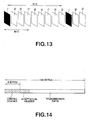
video compression encoder 101 outputs data of an intra-field or intra-frame coded picture, that is I-picture, data of a forward prediction coded picture or P-picture and data of a bidirectionally prediction coded picture or B-picture, in a preset sequence, as shown in Fig.13. In the I-picture, DCT is applied independently without employing correlation with other pictures. In the P-picture, motion compensated prediction coding is done from previous I-picture or P-picture and the difference signal, or so-called prediction error, is discrete cosine transformed. In the B-picture, motion compensated predictive coding is done from the forward and backward I-picture or P-picture and the difference signals is similarly discrete cosine transformed. The period of appearance of the I-picture is termed a group of pictures (GOP). In the present case, M and N are set so that M = 3 and N = 9. - A
transport encoder 106 generates packets from video data encoded by thevideo compression encoder 101, audio data encoded by theaudio encoder 104 and the ancillary information supplied to aninput terminal 107. - Fig.14 shows packet configuration. As shown therein, a transmitted packet has a packet length of 188 bytes. At the leading end of the packet is provided a ring header having a fixed 4-byte length and an adaptation header of a variable length, followed by transmission data consisting of video or audio data.
- In Fig.12, the packet generated by the
transport encoder 106 is supplied to achannel modulator 108 which modulates the packet using a carrier of a pre-set frequency. An output of thechannel modulator 108 is issued at anoutput terminal 109. - It is possible with the ATV system to transmit HDTV signals at a rate of e.g., 19 Mbps by the above-described picture compression. This is lower than the recording rate in the SD mode of the digital VTR (about 25 Mbps). Thus the signals (data) transmitted by the ATV system can be directly recorded with the SD mode of the digital VTR. If the transmitted signals are directly recorded by the digital VTR, there is no necessity of decoding HDTV signals from the transmitted signals and entering the decoded signals into the digital VTR thus obviating waste in hardware. In addition, since recording may be done with the SD mode, the recording time may be prolonged.
- However, if the ATV signals are directly recorded with the SD mode on the digital VTR, variable-length reproduction cannot be achieved for the following reason.
- That is, compression (encoding) pursuant to the MPEG system is done with the ATV system, as explained above. With this system, data of an intra-field or intra-frame coded picture, that is I-picture, data of a forward prediction coded picture or P-picture and data of a bidirectionally prediction coded picture or B-picture are transmitted, as also explained above. During variable-speed reproduction, data of continuous pictures cannot be produced, because the head traverses the track on the magnetic tape. If the data of the continuous pictures is not produced, data of the P-picture and the B-picture cannot be decoded. It is only the intra-picture encoded data, that is I-picture data, that can be decoded. Thus, during variable-speed reproduction, the variable-speed reproduction is enabled by employing solely the data of the I-picture among the reproduced data.
- However, if the signals transmitted in accordance with the ATV system is directly recorded on the digital VTR, the packet carrying the I-picture cannot be sufficiently picked up during the variable-length reproduction. On the other hand, it is indefinite in which position the I-picture data is recorded. Thus it occurs frequently that data of the I-picture corresponding to a pre-set portion of the frame during variable-length reproduction is missing and the frame of such portion cannot be updated for a certain time thus deteriorating the picture quality.
- The present Assignee previously proposed an arrangement in which data of an I-picture is extracted from an input signal bitstream of the ATV system and recorded in an area for variable speed reproduction, while the signals of the ATV system are directly recorded in other areas, such as a video sector. The area for variable speed reproduction is an area from which reproduction may be done during variable speed reproduction. In this case, the area for variable speed reproduction is reproduced during variable speed reproduction and a frame is formed from the data of the I-picture reproduced from this area.
- The present Assignee also proposed the relevant technology in the following two Applications:
- i) European Patent Publication No.0627855 (published data, 1994.12.07)
- ii) European Patent Publication No.0650296 (published data, 199.04.26
- The US applications corresponding to these European Patent Publications are now pending at the US Patent Office. The above-mentioned applications, owned by the present Assignee, are hereby incorporated by reference.
- However, the reproducible area at the time of variable-speed reproduction is changed with the speed of the variable-speed reproduction. Thus it is difficult to set plural variable playback speeds. For example, if data for variable-speed reproduction is recorded in a common area reproducible at 17-tuple, 9-tuple or quadruple speed, variable-speed reproduction at the quadruple speed, 9-tuple speed and 17-tuple speed becomes possible, while it is difficult to achieve variable-speed reproduction at any other speed.
- Various respective aspects of the invention are defined in the appended claims.
- Embodiments of the present invention can provide a recording method and apparatus and a reproducing apparatus for digital video signals capable of easily variable-length reproducing ATV signals directly recorded on a recording medium at plural variable playback speeds.
- Embodiments of the present invention provide a method for recording digital video signals in which encoded digital video signals obtained on adaptively switching from intra-picture encoding to inter-picture encoding and vice versa are recorded as input data on each track of a magnetic tape by azimuth recording system. The method includes the steps of dividing each track of the magnetic tape into a first area and a second area, directly recording the input data in the first area of each track, and sequentially recording variable-speed playback data in the second area of each track. The variable-speed playback data is data among the input data which is obtained on intra-picture recording and which is collected from plural regions divided from a full frame.
- Embodiments of the present invention provide an apparatus for recording digital video signals in which encoded digital video signals obtained on adaptively switching from intra-picture encoding to inter-picture encoding and vice versa are recorded as input data on each track of a magnetic tape by azimuth recording system. The apparatus has a first area in which the input data is directly recorded, a second area provided in each track of the magnetic tape for recording variable-speed playback data therein, and a signal processing circuit for extracting, from data derived from intra-picture encoding, the variable-speed playback data, collected from respective regions divided from a full frame, by variable speed playback data extracting means, to provide variable playback data, and for time-divisional multiplexing of the variable playback data and the input data by multiplexing means for recording on the track of the magnetic tape.
- Embodiments of the present invention provide an apparatus for reproducing digital video signals from a magnetic tape having a track having recorded thereon by an azimuth recording system encoded digital video signals obtained on adaptively switching from intra-picture encoding to inter-picture encoding and vice versa. The track has a first area in which the encoded digital video signals are directly recorded and a second area in which data among said input data which is obtained on intra-picture recording and which is collected from plural regions divided from a full frame is sequentially recorded. The apparatus includes data separating means for separating data reproduced from the first area and data from the second area, from each other, and memory means having a storage capacity of storing one-frame data and supplied with data reproduced from the second area via the data separating means. The apparatus also has interpolating means for interpolating missing portions of data stored in the memory means during variable-speed reproduction and reproduced from the second area, and data switching means for selecting data reproduced from the first area and supplied from the data separating means during normal reproduction and selecting data interpolated by the interpolating means during variable-speed reproduction. The apparatus also includes a signal processing circuit for interpolating missing portions of data reproduced from the second area during variable-speed reproduction and for outputting the interpolated data as playback data for one frame.
- With the method for recording digital video signals according to embodiments of the present invention, each track of the magnetic tape has a first area and a second area, the input data is directly recorded in the first area of each track, and sub-sampled set data for variable-speed reproduction is sequentially recorded in the second area of each track, which sub-sampled data set is data among said input data which is obtained on intra-picture recording and which is collected from plural regions divided from a full frame.
- With the apparatus for recording digital video signals according to embodiments of the present invention, a first area in which the input data is directly recorded and a second area provided in each track of the magnetic tape for recording variable-speed playback data are provided in each track of the magnetic tape, and the variable-speed playback data, collected from respective regions divided from a full frame, are extracted from data derived from intra-picture encoding by variable speed playback data extracting means to provide variable playback sub-sampled data set, and for time-divisional multiplexing of the variable playback sub-sampled data set and the input data by multiplexing means for recording on the track of the magnetic tape. Thus a full frame picture may be constituted on reproducing the sub-sampled set data so that variable-speed reproduction may be achieved at an optional speed.
- On the other hand, with the reproducing apparatus for reproducing digital video signals according to embodiments of the present invention, data for variable-speed playback reproduced from the second area may be stored in memory means and missing data portions may be interpolated by interpolating means for producing playback data of high picture quality.
- Thus, embodiments of the present invention provide a recording method and apparatus and a reproducing apparatus for digital video signals whereby ATV signals directly recorded on a recording medium may be easily variable-speed reproduced at an optional variable reproducing speed.
- Embodiments of the invention provide a method for recording digital video signals whereby data produced by encoding video signals by e.g., the so-called MPEG system can be directly recorded and reproduced pictures having a superior picture quality may be obtained on variable-speed reproduction.
- The invention will now be described by way of example with reference to the accompanying drawings, throughout which like parts are referred to by like references, and in which:
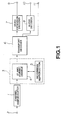
- Fig.1 is a block diagram showing the configuration of a video recording/reproducing system according to the present invention.
- Fig.2 is a block diagram showing the configuration of a VTR recording system according to the present invention.
- Fig.3 is a block diagram showing the configuration of a reproducing system of the digital VTR.
- Fig.4 illustrates the construction of a track on a magnetic tape for the digital VTR.
- Fig.5 illustrates a video sector.
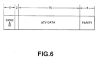
- Fig.6 illustrates a sync block.
- Fig.7 illustrates a sub-sampled set of DC coefficient data recorded in a trick play area.
- Fig.8 shows recording contents of the trick play area.
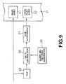
- Fig.9 is a block diagram for illustrating the principle of the recording operation in the digital VTR.
- Fig.10 is a block diagram showing an illustrative construction of a recording system of the digital VTR.
- Fig.11 is a block diagram showing an illustrative construction of a reproducing system of the digital VTR.
- Fig.12 is a block diagram illustrating the construction of a transmission system of the ATV system.
- Fig.13 illustrates the construction of a GOP of the MPEG system.
- Fig.14 illustrates the construction of a packet in the ATV system.
- Referring to the drawings, preferred embodiments of the recording method and apparatus and the reproducing apparatus for digital video signals according to the present invention.
- Fig.1 shows, in a block diagram, a configuration of a video recording/reproducing system employing a digital VTR according to the present invention. In this figure, signals of the ATV system, that is modulated transmission data, enter a
channel demodulator 1. Thechannel data modulator 1 demodulates modulated transmission data to reproduce packets of transmission data. - A
digital VTR 3 of the azimuth recording system includes an interfacing andformat converting section 4. and a recording/reproducingsection 5. Data packets from thechannel modulator 1 are supplied via the interfacing andformat converting section 4 to atransport decoder 6, while being also supplied to the recording/reproducingsection 5. The data supplied to the recording/reproducingsection 5 via the interfacing andformat converting section 4 is recorded in the recording/reproducingsection 5 on the magnetic tape by a rotary head. The interfacing andformat converting section 4 formats data sent to the recording/reproducingsection 5, so that, when the data recorded by the recording/reproducingsection 5 is reproduced, an optimum or at least improved picture will be reproduced, in a manner to be explained subsequently. - The recording/reproducing
section 5 discrete cosine transforms and variable length encodes the video signals by way of signal compression to record the resulting compressed data by the rotary head on the magnetic tape. That is, the recording/reproducingsection 5 can be set to the SD mode of recording video signals of the NTSC system or the HD mode of recording HDTV signals. When directly recording the ATV system signals, supplied via the interfacing andformat converting section 4, that is the transmission data, the recording/reproducingsection 5 is set to the SD mode. - The
transport decoder 6 corrects errors of data packets supplied thereto via the interfacing andformat converting section 4, while taking out data and ancillary information from the data packets. - A
video expansion decoder 7 decodes the Huffman code and effects inverse DCT for expanding the data supplied thereto in order to form baseband signals of the HDTV system. Thevideo expansion decoder 7 and theaudio decoder 8 are fed with an output of thetransport decoder 6. Thevideo expansion decoder 7 expands the transmitted data and converts them into analog signals in order to form HDTV signals. - The HDTV signals, thus formed, are outputted at an
output terminal 9. The audio data is decoded by theaudio decoder 8 to generate audio signals which are outputted at anoutput terminal 10. The output ancillary information from thetransport decoder 6 is outputted at an output terminal 11. - Fig.2 shows, in a block diagram, a configuration of a recording system of a
digital VTR 3 according to the present invention. - In Fig.2, the numeral 21 denotes an input terminal for video signals of the current television system, such as the NTSC system, or HDTV signals. For recording video signals from outside, component video signals of the video signals of the current television system or HDTV system are supplied to the
input terminal 21. The component video signals from theinput terminal 21 are supplied to an A/D converter 22 so as to be converted into digital signals. - A DCT
compression processing circuit 23 encodes and compresses input video signals by DCT and VLC. That is, the component video signals, converted into digital signals from the A/D converter 22, are supplied to DCTcompression processing circuit 23 so as to be blocked, shuffled and discrete cosine transformed to produce data (so-called DCT coefficients) which are buffered with a pre-set buffer unit. The total buffer-based code quantity is estimated and an optimum quantization table which will give the total code quantity less than a pre-set value is determined. Quantization is done in accordance with this optimum quantization table. The resulting quantized data is variable length encoded and subsequently framed. - A switching
circuit 24 is switched between recording the transmitted ATV system signals and recording the video signals from theinput terminal 21. The switchingcircuit 24 has its fixedinput terminal 24A supplied with the ATV signals via the interfacing andformat converting section 4. On the other hand, the switchingcircuit 24 has its fixedinput terminal 24B supplied with an output of the DCTcompression processing circuit 23. For recording the transmitted ATV system signals, the switchingcircuit 24 is set to the side of the fixedinput terminal 24A. For recording the video signals from theinput terminal 21, the switchingcircuit 24 is set to the side of the fixedinput terminal 24B. - A framing
section 25 frames recording data, supplied thereto via the switchingcircuit 24, into a pre-set sync block, while effecting error correction. - An output of the framing
section 25 is fed to achannel encoder 26 and thereby modulated. An output of thechannel encoder 26 is supplied via arecording amplifier 27 to arotary head 28. Therotary head 28 records compressed video signals or HDTV signals from theinput terminal 21 or the ATV signals from theinput terminal 2. - That is, for recording the transmitted ATV system signals in the above-described recording system, the switching
circuit 24 is set to the side of the fixedinput terminal 24A. Thus the ATV system signals, supplied via the interfacing andformat converting section 4, are framed by the framingsection 25 and modulated by thechannel encoder 26 so as to be recorded by therotary head 28 on the magnetic tape. - On the other hand, for recording video signals from the
input terminal 21, the switchingcircuit 24 is set to the side of the fixedinput terminal 24B. Thus the video signals from theinput terminal 21 are encoded and compressed by the DCTcompression processing circuit 23 and framed by the framingcircuit 25 so as to be then modulated by thechannel encoder 26 and subsequently recorded by therotary head 28 on the magnetic tape. - For recording the ATV system signals, the interfacing and
format converting section 4 arrays data so that an area reproducible during variable-speed reproduction will be a trick play area and data of an I-picture (DCT coefficients of a fixed length) will be recorded in this trick play area, in order to improve the picture quality for variable-speed reproduction, as will be explained subsequently. During variable-speed reproduction, the I-picture data is read out from this trick play area and decoded. - Fig.3 shows, in a block diagram, a configuration of a reproducing system of the
digital VTR 3. In this figure, recorded signals of a magnetic tape are reproduced by therotary head 28 and sent via aplayback amplifier 51 to achannel decoder 52. The channel decoder demodulates the playback signals in accordance with a demodulating system which is a counterpart of the modulating system of thechannel encoder 26 of the recording system described above. - A time base corrector (TBC) 53 eliminates jitter in the playback signals. That is, the
TBC 53 is fed with write clocks and readout clocks, which are respectively based on the playback signals and on reference signals, while being also fed with an output of thechannel decoder 52. The TBC eliminates jitter in the playback signals. - A
deframing section 54 is a counterpart of the framingsection 25 of the recording system, and corrects errors in the playback data from theTBC 53. - A switching
circuit 55 is switched between reproducing the ATV system signals and reproducing component video signals. An output of thedeframing section 54 is supplied to aswitching circuit 55. If the playback signals are ATV system signals, the switchingcircuit 55 is switched to the side of a fixedinput terminal 55A. If the playback signals are component video signal, the switchingcircuit 55 is switched to the side of a fixedinput terminal 55B. - A
DCT expansion circuit 56 is a counterpart of the DCTcompression processing circuit 23. That is, theDCT expansion circuit 56 decodes variable length codes, which are playback data, and inverse discrete cosine transforms the decoded data for expanding the compression-recorded component video signals into the original baseband video signals. That is, an output of the fixedinput terminal 55B of the switchingcircuit 55 is supplied to theDCT expansion circuit 56 whereby playback data is restored to baseband video signals which are outputted at anoutput terminal 57. - An output of the terminal 55A of the switching
circuit 55 is supplied to apacket selection circuit 59. For usual reproduction of the ATV system signals, thepacket selection circuit 59 selects all of the packets of the playback data supplied thereto via the switchingcircuit 55. On the other hand, for variable speed reproduction, only I-picture data are valid. Thus, for variable speed reproduction, thepacket selection circuit 59 selects and outputs data packets of the I-picture data obtained on reproducing the trick play area. An output of thepacket selection circuit 59 is issued at anoutput terminal 60. - A
controller 61 performs control of switching between normal reproduction and variable speed reproduction. Thecontroller 61 is fed with a mode setting signal from aninput section 62. Aservo circuit 63 and thepacket selection circuit 59 are controlled responsive to this mode setting signal. During variable speed reproduction of the ATV system signals, theservo circuit 63 effects phase control and tape speed control by exploiting tracking signals, such as ATF signals, for fixing the phase so that the position traced by the head will be perpetually the same position on the track. That is, during variable speed reproduction, the trick play area is reproduced, so that the I-picture data recorded in the trick play area will be reproduced. - An output of the
output terminal 60 is sent to thevideo expansion decoder 7 of Fig.1 for decoding. In the present embodiment, all I-picture data for one full frame is recorded in the trick play area. Consequently, during variable-speed reproduction, the actual picture is updated with one full frame as a unit, thus giving an easy-to-see reproduced picture. - The variable speed reproduction in the digital VTR according to the present invention is explained in detail.
- Fig.4 shows the configuration of one track in the present digital VTR. Each track is constituted by an audio sector SEC1, a video sector SEC2 and a subcode sector SEC3. The video sector SEC2 has a capacity corresponding to video data of 135 sync blocks, as shown in Fig.5. A 5-byte sync and ID are appended at the leading end of each sync block. Spare data (VAUX) corresponding to 3 sync blocks are appended to these video data. Using product codes, double error correction codes (C1 and C2) are appended.
- Thus the video data corresponding to 135 sync blocks can be recorded in each track of the video sector SEC2. For the SD mode, the rpm of the rotary drum is 150 Hz. Two heads with different azimuth angles are mounted on the rotary drum so that data is azimuth-recorded on ten tracks per frame. For recording ATV system signals, that is ATV signals, the data area in each sync block (1 SB) is 77 bytes or 77 X 8 = 616 bits, as shown in Fig.6.
- Assuming that each frame of a color input picture having a 4:2:0 structure is made up of 1920 X 10180 pixels, the number of DCT blocks for luminance data in one frame is (1920/8) X (1080/8) = 240 X 135 DCT blocks, while that for chrominance data is (240/2) X (135/2) = 120 X 68 DCT blocks.
- Then, as shown in Fig.7, a frame is divided in ten in the horizontal direction and in six in the vertical direction. From each divided area, 1 DCT block is picked up, and 9 dummy blocks are provided. Thus, luminance data becomes (240/10) X ((135 + 9)/6) = 24 X 24 blocks. On the other hand, 4 dummy blocks are provided, so that each chrominance data becomes (120/10) X ((68 + 4)/6) = 12 X 12 blocks, These blocks are termed sub-sampled DC coefficient sets.
- A first set of sub-sampled DC coefficients, denoted by O in Fig.7, is collected and sequentially recorded in the trick play area. Then, another set of sub-sample DC coefficients, denoted byin Fig.7, is collected and sequentially recorded in the trick play area. In this manner, all DC coefficient data in one frame are recorded in the trick play areas TP, as shown in Fig.8.

- If the DC coefficient data is of 10 bits, each set of the sub-sample DC coefficients is 10 X 6 X 10 = 600 bits, so that it can be recorded in the above-mentioned sync bit of 616 bits.
- Consequently, during reproduction, each frame by the sub-sampled DCT coefficients can be constituted by sub-sampled DC coefficients, if 1 SB can be reproduced. In effect, 3 SBs of the luminance data and chrominance data give sub-sampled DC coefficient sets capable of constituting one frame. With the 4:2:0 structure color picture data, since the number of the chrominance data is one-half that of the luminance data, the chrominance data can be recorded twice by way of duplex recording.
- For variable-speed reproduction, if the reproducing speed is such that three or more SBs exist in each burst, data of the sub-sampled DC coefficient sets for one frame can be reproduced at an arbitrary speed. On the other hand, the lower the speed, the shorter is the interval between head scans, so that data of many sub-sample DC coefficient sets can be reproduced. An actual playback picture is constituted by interpolating other non-reproduced DC coefficient data with data of the sub-sampled DCT coefficient sets. Consequently, since data of many sub-sampled DC coefficient sets can be reproduced at lower speeds, the sub-sampling interval becomes shorter to enable a picture of a higher quality to be constituted.
- If the trick play area for one track is of 3 SBs, trick play data is recorded over 24 × 24 = 576 tracks. Thus, all I-pictures can not necessarily be recorded, resulting in the lowering of the updating ratio during playback. For example, if the trick play area for one track is of 12 SBs, it can be recorded with 576/(12/3) = 144 tracks.
- As shown by four shaded areas of a track in Fig.8, plural trick play areas, inclusive of the trick play area in black, may be provided for one track. Plural such tracks may be arranged side-by-side.
- Fig. 9 schematically illustrates recording/reproduction of ATV signals. A main area Al and a trick play area A2 are provided on a video sector of a
magnetic tape 31. The trick play area A2 corresponds to the above-described allowance recording area which is provided in an area reproducible during variable-speed reproduction. During recording, an input bitstream of ATV signals or a data stream is directly recorded in the main area A1, while being supplied to aVLD decoding circuit 34. TheVLD decoding circuit 34 decodes the ATV signals to detect breaking points of the variable length encoded DCT coefficients in order to transmit fixed length DC coefficient data to adata separating circuit 36. - Based upon the sub-sampled pattern supplied from the
sub-sampled pattern generator 35, thedata separating circuit 36 extracts sub-sampled DC coefficient data, as data required for variable-length reproduction, from the bitstream of the DC coefficient data supplied form theVLD decoding circuit 34, based upon the sub-sampled pattern supplied from thesub-sampled pattern generator 35. - The data required for variable-speed reproduction are only DC coefficient data of respective blocks of the I-picture of ATV signals. The I-picture data required for this variable-speed reproduction is supplied to an
EOB appending circuit 37. TheEOB appending circuit 37 appends an EOB specifying an end of block. The data for the I-frame necessary for variable-speed reproduction, that is DCT coefficient data of respective blocks of the I-picture, is recorded in the trick play area A2 as sub-sampled DC coefficient set data. - During normal reproduction, playback signals from the main area A1 are decoded. During variable-speed reproduction, only the trick play area A2 is reproduced and decoded. Consequently, during variable-length reproduction, only DC coefficient data of respective blocks of the I-picture are sent to the
video expansion decoder 7. In order for these data to be decoded by a usual video expansion decoder, the transmitted data construction must be the same as the construction of a usual bitstream. For this reason, the EOB data specifying end of block is appended after extraction of the dc component from the respective blocks during recording. - The illustrative construction of the interfacing and
format converting section 4, framingsection 25,deframing section 54 and thepacket selection circuit 59, making up the present digital VTR, is now explained. The circuits having the same functions as those of the circuits shown in Figs.1 to 3 and 9 are denoted by the same numerals and the corresponding explanation is omitted. - Referring to Fig.10, the interfacing and
format converting section 4 constituting the recording system of thedigital VTR 3 includes abuffer memory 71 for temporarily storing ATV signals, and ademultiplexor 72 for extracting video signal packets from the ATV signals. The interfacing andformat converting section 4 also includes adepacketing circuit 73 for resolving the video signal packets from thedemultiplexor 72 into respective packets, and asyntax analysis circuit 74 for analyzing the header of each packet for extracting I-picture data. The interfacing andformat converting section 4 also includes the above-mentionedVLD decoding circuit 34 for detecting the breaking points of the DCT coefficients and the above-mentioneddata separating circuit 36 for extracting trick play data made up of sub-sampled DC coefficient sets of the DCT coefficient data of respective blocks of the I-picture based upon the sub-sampled pattern supplied from thesub-sampled pattern generator 35. The interfacing andformat converting section 4 finally includes amultiplexor 75 for time-divisionally multiplexing trick play data from thedata separating circuit 36 and ATV signals stored in thebuffer memory 71, and acontrol circuit 76 for controlling themultiplexor 75. - The interfacing and
format converting section 4 is so configured that, when it extracts trick play data required for variable-speed reproduction from the ATV signals and inserts the trick play data into the ATV signals for forming recording data by time-divisional multiplexing, the distance from a recording start position to the trick play area on each track differs between neighboring blocks. - That is, the
buffer memory 71 temporarily stores the input ATV signals and reads out the stored ATV signals on e.g., a sync block basis in order to transmit the read-out signals to themultiplexor 75. - On the other hand, the
demultiplexor 72 extracts the video signal packets from the ATV signals to supply the extracted packets to thedepacketing circuit 73 which then resolves the video signal packets into respective packets. - The
syntax analysis circuit 74 analyzes the headers of the respective packets resolved by thedepacketing circuit 73 and extracts the packets containing the I-picture data. The extracted packets are supplied to thedata separating circuit 36. - The
VLD decoding circuit 34 decodes the packets supplied from thedepacketing circuit 73 and detects the breaking point of the variable length encoded DCT coefficients to transmit the fixed-length DCT coefficients to thedata separating circuit 36. - The
data separating circuit 36 extracts, from the data of the packets supplied from theVLD decoding circuit 34, trick play data made up of sub-sampled DCT coefficient sets of the DCT coefficient data of respective blocks of the I-picture, based upon the sub-sampling pattern supplied from thesub-sampling pattern generator 35, and transmits the extracted data to theEOB appending circuit 37. TheEOB appending circuit 37 appends the EOB to the low-range coefficients of the respective blocks of the I-picture and transmits the resulting data on the sync block basis to themultiplexor 75. - The
multiplexor 75 time-divisionally multiplexes the ATV signals read out from thebuffer memory 71 and the trick play data from thedata separating circuit 36. - That is, the
control circuit 76 time-divisionally multiplexes the ATV signals read out from thebuffer memory 71 and the trick play data from thedata separating circuit 36. The recording data thus obtained on time-divisionally multiplexing the ATV signals and the trick play data are supplied via the switchingcircuit 24 shown in Fig.2 to the framingsection 25. - The framing
section 25 has aC2 parity circuit 77 for appending the outer parity and a framingcircuit 78 for appending the inner parity, as shown in Fig.10. TheC2 parity circuit 77 appends the outer parity C2 to recording data supplied from themultiplexor 75, while the framingcircuit 78 appends the inner parity C1 and the 5-byte sync and ID to the recording data and transmits the resulting data to thechannel encoder 26. - Thus the sub-sampling DCT coefficient sets of the DCT coefficient data of respective blocks of the I-picture are recorded on the trick play area.
- The
deframing section 54, constituting the reproducing system of thedigital VTR 3, includes adeframing circuit 81 for correcting the playback data for error by the inner parity C1 and for correcting the playback data for error by the outer parity C2, as shown in Fig.11. - The
deframing circuit 81 corrects the playback data supplied from thechannel decoder 52 via theTBC 53 shown in Fig.3 for errors by the inner parity C1 and routes the resulting data to theerror correcting circuit 82. - The
error correcting circuit 82 corrects the playback data supplied during normal reproduction for errors by the outer parity C2. However, theerror correcting circuit 82 does not perform error correction during variable-speed reproduction of ATV signals, that is, it does not correct the playback data constituted solely by the trick play data for errors. An output of theerror correction circuit 82 is supplied via the switchingcircuit 55 shown in Fig.3 to theDCT expansion circuit 56 and via the switchingcircuit 55 to thepacket selection circuit 59 during reproduction of the component video signals and during reproduction of the ATV signals, respectively. - Turning again to Fig.11, the
packet selection circuit 59 includes ademultiplexor 83 for distributing playback data between normal reproduction and variable-speed reproduction, and abuffer memory 84 for temporarily storing playback data during variable-speed reproduction. Thecircuit 59 also includes aninterpolation circuit 85 for interpolating the playback data stored in thebuffer memory 84, anerror processing circuit 86 for setting data not corrected for errors by the inner parity C1 to zero, and aselector 87. - The
demultiplexor 83 decodes the packets of the ATV signals and transmits all packets of the playback data supplied from theerror correcting circuit 82 to theselector 87 during normal reproduction of the ATV signals. while transmitting sub-sampled DCT coefficient sets of the DCT coefficient data of respective blocks of the I-picture reproduced as the trick play data required for variable-speed reproduction from the trick play area to thebuffer memory 84 during variable-speed reproduction. - The
buffer memory 84 temporarily stores data of the sub-sampled DCT coefficient data reproduced from the trick play area and, at a time point when data for one full frame is readied, transmits the stored DCT coefficient data via the interpolatingcircuit 85 to theerror processing circuit 86. The interpolatingcircuit 85 interpolates other DCT coefficient data, which have failed to be reproduced, with data of the sub-sampled DCT coefficient sets supplied from thebuffer memory 84. Theerror processing circuit 86 sets data, for which error correction was unable to be done in thedeframing circuit 81 with the aid of the inner parity C1, to zero, and transmits data of the I-picture, made up of DCT coefficient data for one frame interpolated by the interpolatingcircuit 85, to theselector 87. - The
selector 87 selects the playback data directly supplied from thedemultiplexor 83 during normal reproduction of the ATV signals, while selecting the playback data supplied from theerror processing circuit 85 during variable-speed reproduction. The selector routes the selected data to thevideo expansion decoder 7 shown in Fig.1. - In the trick play area, one full frame of the I-picture, made up only of DCT coefficients, is recorded. If simply the reproduced picture is sent to the
video expansion decoder 7, there is no insurance that the display timing (1/30 second) be matched to the timing of the I-picture boundary, such that the actual picture is not updated on the frame basis but only partial updating results. Thus, before sending playback data to thevideo expansion decoder 7, one-frame data is fully reproduced and readied and subsequently the playback data is supplied to thevideo expansion decoder 7. This enables an actual picture to be updated on the frame basis to permit a variable-speed reproduced picture which is easy to view. It is also possible to use a common buffer memory for thebuffer memory 71 of the recording system and for thebuffer memory 84 of the playback system and to switch the common buffer for recording and reproduction. - Although the foregoing description has been made of the digital VTR configured for recording ATV system signals, it is to be noted that similar techniques may be applied to a VTR configured for recording input data obtained on encoding video signals adaptively switched between intra-picture encoding and inter-picture predictive encoding.
Claims (18)
- A method for recording digital video signals in which encoded digital video signals obtained on adaptively switching from intra-picture encoding to inter-picture encoding and vice versa are recorded as input data on each track of a magnetic tape by azimuth recording system, comprising
dividing each track of the magnetic tape into a first area and a second area,
directly recording the input data in the first area of each track, and
sequentially recording variable-speed playback data in said second area of each track, said variable-speed playback data being data among said input data which is obtained on intra-picture recording and which is collected from plural regions divided from a full frame. - The method as claimed in claim 1, wherein said second area is provided across a plurality of tracks.
- The method as claimed in claim 2, wherein said second area is provided at plural places in one track.
- The method as claimed in claim 3, wherein said input data is made up of plural sync blocks.
- The method as claimed in claim 4, wherein an end-specifying data is appended to an end part of said input data constituted by plural sync blocks.
- The method as claimed in claim 5, wherein said second area is constituted by a plurality of said sync blocks.
- An apparatus for recording digital video signals in which encoded digital video signals obtained on adaptively switching from intra-picture encoding to inter-picture encoding and vice versa are recorded as input data on each track of a magnetic tape by azimuth recording system, comprising
a first area in which the input data is directly recorded,
a second area provided in each track of the magnetic tape for recording variable-speed playback data therein, and
a signal processing circuit for extracting, from data derived from intra-picture encoding, the variable-speed playback data, collected from respective regions divided from a full frame, by variable speed playback data extracting means, to provide variable playback data, and for time-divisional multiplexing of said variable playback data and said input data by multiplexing means for recording on the track of the magnetic tape. - The method as claimed in claim 7, wherein said second area is provided across a plurality of tracks.
- The method as claimed in claim 8, wherein said second area is provided at plural places in one track.
- The method as claimed in claim 9, wherein said input data is made up of plural sync blocks.
- The method as claimed in claim 10, wherein an end-specifying data is appended to an end part of said input data constituted by plural sync blocks.
- The method as claimed in claim 11, wherein said second area is constituted by a plurality of said sync blocks.
- An apparatus for reproducing digital video signals from a magnetic tape having a track having recorded thereon by an azimuth recording system encoded digital video signals obtained on adaptively switching from intra-picture encoding to inter-picture encoding and vice versa, said track having a first area in which the encoded digital video signals are directly recorded and a second area in which data among said input data which is obtained on intra-picture recording and which is collected from plural regions divided from a full frame is sequentially recorded, comprising
data separating meas for separating data reproduced from said first area and data from said second area, from each other,
memory means having a storage capacity of storing one-frame data and supplied with data reproduced from said second area via said data separating means,
interpolating means for interpolating missing portions of data stored in the memory means during variable-speed reproduction and reproduced from the second area,
data switching means for selecting data reproduced from said first area and supplied from said data separating means during normal reproduction and selecting data interpolated by said interpolating means during variable-speed reproduction, and
a signal processing circuit for interpolating missing portions of data reproduced from said second area during variable-speed reproduction and for outputting the interpolated data as playback data for one frame. - The apparatus as claimed in claim 13, wherein said second area is provided across a plurality of tracks.
- The apparatus as claimed in claim 14, wherein said second area is provided at plural places in one track.
- The apparatus as claimed in claim 15, wherein said input data is made up of plural sync blocks.
- The apparatus as claimed in claim 16, wherein an end-specifying data is appended to an end part of said input data constituted by plural sync blocks.
- The apparatus as claimed in claim 17, wherein said second area is constituted by a plurality of said sync blocks.
Applications Claiming Priority (3)
| Application Number | Priority Date | Filing Date | Title |
|---|---|---|---|
| JP142042/94 | 1994-06-23 | ||
| JP6142042A JPH089319A (en) | 1994-06-23 | 1994-06-23 | Method and device for recording and device for reproducing digital video signal |
| JP14204294 | 1994-06-23 |
Publications (3)
| Publication Number | Publication Date |
|---|---|
| EP0689364A2 true EP0689364A2 (en) | 1995-12-27 |
| EP0689364A3 EP0689364A3 (en) | 1996-06-26 |
| EP0689364B1 EP0689364B1 (en) | 2000-03-22 |
Family
ID=15306041
Family Applications (1)
| Application Number | Title | Priority Date | Filing Date |
|---|---|---|---|
| EP95304378A Expired - Lifetime EP0689364B1 (en) | 1994-06-23 | 1995-06-22 | Recording and reproducing digital video signals |
Country Status (7)
| Country | Link |
|---|---|
| US (1) | US5946446A (en) |
| EP (1) | EP0689364B1 (en) |
| JP (1) | JPH089319A (en) |
| CN (1) | CN1122987A (en) |
| AT (1) | ATE191117T1 (en) |
| CA (1) | CA2152129A1 (en) |
| DE (1) | DE69515736T2 (en) |
Cited By (1)
| Publication number | Priority date | Publication date | Assignee | Title |
|---|---|---|---|---|
| US7174055B2 (en) | 1999-01-28 | 2007-02-06 | Kabushiki Kaisha Toshiba | Image information describing method, video retrieval method, video reproducing method, and video reproducing apparatus |
Families Citing this family (30)
| Publication number | Priority date | Publication date | Assignee | Title |
|---|---|---|---|---|
| KR0165439B1 (en) * | 1995-09-14 | 1999-03-20 | 김광호 | Device and method of screen construction for dvcr |
| US6389218B2 (en) * | 1998-11-30 | 2002-05-14 | Diva Systems Corporation | Method and apparatus for simultaneously producing compressed play and trick play bitstreams from a video frame sequence |
| JP3557371B2 (en) * | 1999-07-15 | 2004-08-25 | 松下電器産業株式会社 | AV decoder control method and AV decoder control device |
| JP4328995B2 (en) * | 2000-03-30 | 2009-09-09 | ソニー株式会社 | Magnetic tape recording apparatus and method, and recording medium |
| JP3380517B2 (en) * | 2000-03-30 | 2003-02-24 | 松下電器産業株式会社 | Special reproduction data creation device and medium |
| US6859877B2 (en) * | 2000-06-12 | 2005-02-22 | Canon Kabushiki Kaisha | Image processing apparatus and method, and computer readable memory medium storing program for executing image processing |
| JP3734020B2 (en) * | 2001-04-12 | 2006-01-11 | ソニー株式会社 | Information recording apparatus and method, data structure, program recording medium, and program |
| JP2002374500A (en) * | 2001-06-18 | 2002-12-26 | Sony Corp | Device and method for image recording, device and method for image reproduction, magnetic tape, program storage medium, and program |
| US7257312B2 (en) * | 2001-10-23 | 2007-08-14 | Thomson Licensing | Fast motion trick mode using dummy predictive pictures |
| CN1321066C (en) * | 2005-08-12 | 2007-06-13 | 安泰科技股份有限公司 | Zirconium dioxide nano powder material preparation method |
| EP1999883A4 (en) | 2006-03-14 | 2013-03-06 | Divx Llc | Federated digital rights management scheme including trusted systems |
| US8997161B2 (en) * | 2008-01-02 | 2015-03-31 | Sonic Ip, Inc. | Application enhancement tracks |
| CA2749170C (en) | 2009-01-07 | 2016-06-21 | Divx, Inc. | Singular, collective and automated creation of a media guide for online content |
| US8539535B2 (en) * | 2009-11-30 | 2013-09-17 | Time Warner Cable Enterprises Llc | Methods and apparatus for supporting VOD requests in a system with hierarchical content stores |
| CA2782825C (en) | 2009-12-04 | 2016-04-26 | Divx, Llc | Elementary bitstream cryptographic material transport systems and methods |
| US9247312B2 (en) | 2011-01-05 | 2016-01-26 | Sonic Ip, Inc. | Systems and methods for encoding source media in matroska container files for adaptive bitrate streaming using hypertext transfer protocol |
| US8994214B2 (en) | 2011-08-09 | 2015-03-31 | Bae Systems Controls Inc. | Hybrid electric generator set |
| US9467708B2 (en) | 2011-08-30 | 2016-10-11 | Sonic Ip, Inc. | Selection of resolutions for seamless resolution switching of multimedia content |
| US8909922B2 (en) | 2011-09-01 | 2014-12-09 | Sonic Ip, Inc. | Systems and methods for playing back alternative streams of protected content protected using common cryptographic information |
| US8964977B2 (en) | 2011-09-01 | 2015-02-24 | Sonic Ip, Inc. | Systems and methods for saving encoded media streamed using adaptive bitrate streaming |
| US8914836B2 (en) | 2012-09-28 | 2014-12-16 | Sonic Ip, Inc. | Systems, methods, and computer program products for load adaptive streaming |
| US9313510B2 (en) | 2012-12-31 | 2016-04-12 | Sonic Ip, Inc. | Use of objective quality measures of streamed content to reduce streaming bandwidth |
| US9191457B2 (en) | 2012-12-31 | 2015-11-17 | Sonic Ip, Inc. | Systems, methods, and media for controlling delivery of content |
| US9906785B2 (en) | 2013-03-15 | 2018-02-27 | Sonic Ip, Inc. | Systems, methods, and media for transcoding video data according to encoding parameters indicated by received metadata |
| US10397292B2 (en) | 2013-03-15 | 2019-08-27 | Divx, Llc | Systems, methods, and media for delivery of content |
| US9094737B2 (en) | 2013-05-30 | 2015-07-28 | Sonic Ip, Inc. | Network video streaming with trick play based on separate trick play files |
| US9247317B2 (en) | 2013-05-30 | 2016-01-26 | Sonic Ip, Inc. | Content streaming with client device trick play index |
| US9967305B2 (en) | 2013-06-28 | 2018-05-08 | Divx, Llc | Systems, methods, and media for streaming media content |
| US9866878B2 (en) | 2014-04-05 | 2018-01-09 | Sonic Ip, Inc. | Systems and methods for encoding and playing back video at different frame rates using enhancement layers |
| US10498795B2 (en) | 2017-02-17 | 2019-12-03 | Divx, Llc | Systems and methods for adaptive switching between multiple content delivery networks during adaptive bitrate streaming |
Citations (2)
| Publication number | Priority date | Publication date | Assignee | Title |
|---|---|---|---|---|
| EP0627855A2 (en) | 1993-05-31 | 1994-12-07 | Sony Corporation | Digital video signal recording and/or reproduction |
| EP0650296A2 (en) | 1993-10-22 | 1995-04-26 | Sony Corporation | Recording and reproducing digital video data |
Family Cites Families (12)
| Publication number | Priority date | Publication date | Assignee | Title |
|---|---|---|---|---|
| JP2684695B2 (en) * | 1988-08-05 | 1997-12-03 | キヤノン株式会社 | Data recording device |
| EP0482888B1 (en) * | 1990-10-25 | 1997-06-04 | Matsushita Electric Industrial Co., Ltd. | Video signal recording/reproducing apparatus |
| US5282049A (en) * | 1991-02-08 | 1994-01-25 | Olympus Optical Co., Ltd. | Moving-picture data digital recording and reproducing apparatuses |
| DE69233538T2 (en) * | 1991-09-30 | 2006-06-29 | Kabushiki Kaisha Toshiba, Kawasaki | Device for processing band-compressed signals for recording / playback |
| EP0551694A1 (en) * | 1992-01-15 | 1993-07-21 | Matsushita Electric Industrial Co., Ltd. | Method of recording a digital video signal |
| EP0691788A1 (en) * | 1992-03-24 | 1996-01-10 | Kabushiki Kaisha Toshiba | Variable length code recording/playback apparatus |
| US5583650A (en) * | 1992-09-01 | 1996-12-10 | Hitachi America, Ltd. | Digital recording and playback device error correction methods and apparatus for use with trick play data |
| JPH06150568A (en) * | 1992-11-06 | 1994-05-31 | Sony Corp | Data recording device |
| JP2855067B2 (en) * | 1992-11-28 | 1999-02-10 | 三星電子株式会社 | Digital VCR image recording method |
| TW323875U (en) * | 1992-12-04 | 1997-12-21 | Sony Corp | Digital video and audio signal recording and reproducing apparatus |
| US5377051A (en) * | 1993-01-13 | 1994-12-27 | Hitachi America, Ltd. | Digital video recorder compatible receiver with trick play image enhancement |
| CA2115976C (en) * | 1993-02-23 | 2002-08-06 | Saiprasad V. Naimpally | Digital high definition television video recorder with trick-play features |
-
1994
- 1994-06-23 JP JP6142042A patent/JPH089319A/en not_active Withdrawn
-
1995
- 1995-06-19 CA CA002152129A patent/CA2152129A1/en not_active Abandoned
- 1995-06-22 AT AT95304378T patent/ATE191117T1/en not_active IP Right Cessation
- 1995-06-22 EP EP95304378A patent/EP0689364B1/en not_active Expired - Lifetime
- 1995-06-22 DE DE69515736T patent/DE69515736T2/en not_active Expired - Fee Related
- 1995-06-23 CN CN95107620.5A patent/CN1122987A/en active Pending
-
1997
- 1997-09-19 US US08/934,438 patent/US5946446A/en not_active Expired - Fee Related
Patent Citations (2)
| Publication number | Priority date | Publication date | Assignee | Title |
|---|---|---|---|---|
| EP0627855A2 (en) | 1993-05-31 | 1994-12-07 | Sony Corporation | Digital video signal recording and/or reproduction |
| EP0650296A2 (en) | 1993-10-22 | 1995-04-26 | Sony Corporation | Recording and reproducing digital video data |
Cited By (1)
| Publication number | Priority date | Publication date | Assignee | Title |
|---|---|---|---|---|
| US7174055B2 (en) | 1999-01-28 | 2007-02-06 | Kabushiki Kaisha Toshiba | Image information describing method, video retrieval method, video reproducing method, and video reproducing apparatus |
Also Published As
| Publication number | Publication date |
|---|---|
| US5946446A (en) | 1999-08-31 |
| EP0689364B1 (en) | 2000-03-22 |
| EP0689364A3 (en) | 1996-06-26 |
| CA2152129A1 (en) | 1995-12-24 |
| DE69515736T2 (en) | 2000-07-20 |
| CN1122987A (en) | 1996-05-22 |
| JPH089319A (en) | 1996-01-12 |
| ATE191117T1 (en) | 2000-04-15 |
| DE69515736D1 (en) | 2000-04-27 |
Similar Documents
| Publication | Publication Date | Title |
|---|---|---|
| EP0689364B1 (en) | Recording and reproducing digital video signals | |
| EP0613297B1 (en) | Digital high definition television video recorder with trick-play features | |
| KR100367195B1 (en) | Apparatus and Method for transmitting recording and reproducing digital data | |
| US7398007B2 (en) | Data recording and reproducing method and apparatus for adding synchronization data during recording and detecting synchronization data during reproduction | |
| KR100676093B1 (en) | Video data recording apparatus, video data recording method, video data reproducing apparatus, video data reproducing method, video data recording and reproducing apparatus, and video data recording and reproducing method | |
| US5712946A (en) | Recording/reproducing video signals with a plurality of playback speeds | |
| KR100838902B1 (en) | Stream processor | |
| US7536080B2 (en) | Signal processing apparatus | |
| KR100796885B1 (en) | Signal processor | |
| JP2000138897A (en) | Data processor and data recorder | |
| KR100739262B1 (en) | Recording apparatus and method, and reproducing apparatus and method | |
| US6741793B1 (en) | Data transmitting apparatus and method thereof, recording apparatus, and recording and reproducing apparatus | |
| US5648855A (en) | Method and apparatus for varying-speed reproduction of digital video signals | |
| JP2000324448A (en) | Data recording device, data recording/reproducing device, data recording method and data recording/reproducing method | |
| KR100681992B1 (en) | Recording apparatus and method | |
| JP3257243B2 (en) | Digital video signal recording method and recording apparatus | |
| JPH09130744A (en) | Digital recording and reproducing device | |
| JP3978903B2 (en) | Data recording apparatus, data recording method, data processing apparatus, and data processing method | |
| JP3572659B2 (en) | Digital video signal recording device, reproducing device, recording / reproducing device, and recording medium | |
| JPH089323A (en) | Recording method, recording device, recording medium, reproducing device and recording and recording device for digital video signal | |
| JP2000152174A (en) | Image data processor its method and image data recorder | |
| JP2000156052A (en) | Recording device and method, reproducing device and method, recording/reproducing device and video signal recording/reproducing device |
Legal Events
| Date | Code | Title | Description |
|---|---|---|---|
| PUAI | Public reference made under article 153(3) epc to a published international application that has entered the european phase |
Free format text: ORIGINAL CODE: 0009012 |
|
| AK | Designated contracting states |
Kind code of ref document: A2 Designated state(s): AT DE FR GB IT NL |
|
| PUAL | Search report despatched |
Free format text: ORIGINAL CODE: 0009013 |
|
| AK | Designated contracting states |
Kind code of ref document: A3 Designated state(s): AT DE FR GB IT NL |
|
| 17P | Request for examination filed |
Effective date: 19961112 |
|
| 17Q | First examination report despatched |
Effective date: 19980827 |
|
| GRAG | Despatch of communication of intention to grant |
Free format text: ORIGINAL CODE: EPIDOS AGRA |
|
| GRAG | Despatch of communication of intention to grant |
Free format text: ORIGINAL CODE: EPIDOS AGRA |
|
| GRAH | Despatch of communication of intention to grant a patent |
Free format text: ORIGINAL CODE: EPIDOS IGRA |
|
| GRAH | Despatch of communication of intention to grant a patent |
Free format text: ORIGINAL CODE: EPIDOS IGRA |
|
| GRAA | (expected) grant |
Free format text: ORIGINAL CODE: 0009210 |
|
| AK | Designated contracting states |
Kind code of ref document: B1 Designated state(s): AT DE FR GB IT NL |
|
| REF | Corresponds to: |
Ref document number: 191117 Country of ref document: AT Date of ref document: 20000415 Kind code of ref document: T |
|
| REF | Corresponds to: |
Ref document number: 69515736 Country of ref document: DE Date of ref document: 20000427 |
|
| ITF | It: translation for a ep patent filed |
Owner name: SOCIETA' ITALIANA BREVETTI S.P.A. |
|
| ET | Fr: translation filed | ||
| PLBE | No opposition filed within time limit |
Free format text: ORIGINAL CODE: 0009261 |
|
| STAA | Information on the status of an ep patent application or granted ep patent |
Free format text: STATUS: NO OPPOSITION FILED WITHIN TIME LIMIT |
|
| 26N | No opposition filed | ||
| PGFP | Annual fee paid to national office [announced via postgrant information from national office to epo] |
Ref country code: FR Payment date: 20010611 Year of fee payment: 7 |
|
| PGFP | Annual fee paid to national office [announced via postgrant information from national office to epo] |
Ref country code: AT Payment date: 20010613 Year of fee payment: 7 |
|
| PGFP | Annual fee paid to national office [announced via postgrant information from national office to epo] |
Ref country code: DE Payment date: 20010618 Year of fee payment: 7 |
|
| PGFP | Annual fee paid to national office [announced via postgrant information from national office to epo] |
Ref country code: GB Payment date: 20010620 Year of fee payment: 7 |
|
| PGFP | Annual fee paid to national office [announced via postgrant information from national office to epo] |
Ref country code: NL Payment date: 20010628 Year of fee payment: 7 |
|
| REG | Reference to a national code |
Ref country code: GB Ref legal event code: IF02 |
|
| PG25 | Lapsed in a contracting state [announced via postgrant information from national office to epo] |
Ref country code: GB Free format text: LAPSE BECAUSE OF NON-PAYMENT OF DUE FEES Effective date: 20020622 Ref country code: AT Free format text: LAPSE BECAUSE OF NON-PAYMENT OF DUE FEES Effective date: 20020622 |
|
| PG25 | Lapsed in a contracting state [announced via postgrant information from national office to epo] |
Ref country code: NL Free format text: LAPSE BECAUSE OF NON-PAYMENT OF DUE FEES Effective date: 20030101 Ref country code: DE Free format text: LAPSE BECAUSE OF NON-PAYMENT OF DUE FEES Effective date: 20030101 |
|
| GBPC | Gb: european patent ceased through non-payment of renewal fee |
Effective date: 20020622 |
|
| PG25 | Lapsed in a contracting state [announced via postgrant information from national office to epo] |
Ref country code: FR Free format text: LAPSE BECAUSE OF NON-PAYMENT OF DUE FEES Effective date: 20030228 |
|
| NLV4 | Nl: lapsed or anulled due to non-payment of the annual fee |
Effective date: 20030101 |
|
| REG | Reference to a national code |
Ref country code: FR Ref legal event code: ST |
|
| PG25 | Lapsed in a contracting state [announced via postgrant information from national office to epo] |
Ref country code: IT Free format text: LAPSE BECAUSE OF NON-PAYMENT OF DUE FEES Effective date: 20050622 |