EP0689057A2 - Monitoring device secured to power distribution system conductors - Google Patents
Monitoring device secured to power distribution system conductors Download PDFInfo
- Publication number
- EP0689057A2 EP0689057A2 EP95109111A EP95109111A EP0689057A2 EP 0689057 A2 EP0689057 A2 EP 0689057A2 EP 95109111 A EP95109111 A EP 95109111A EP 95109111 A EP95109111 A EP 95109111A EP 0689057 A2 EP0689057 A2 EP 0689057A2
- Authority
- EP
- European Patent Office
- Prior art keywords
- housing
- electrically conductive
- electrical conductor
- conductors
- passage
- Prior art date
- Legal status (The legal status is an assumption and is not a legal conclusion. Google has not performed a legal analysis and makes no representation as to the accuracy of the status listed.)
- Granted
Links
Images


Classifications
-
- G—PHYSICS
- G01—MEASURING; TESTING
- G01R—MEASURING ELECTRIC VARIABLES; MEASURING MAGNETIC VARIABLES
- G01R15/00—Details of measuring arrangements of the types provided for in groups G01R17/00 - G01R29/00, G01R33/00 - G01R33/26 or G01R35/00
- G01R15/14—Adaptations providing voltage or current isolation, e.g. for high-voltage or high-current networks
- G01R15/142—Arrangements for simultaneous measurements of several parameters employing techniques covered by groups G01R15/14 - G01R15/26
-
- G—PHYSICS
- G01—MEASURING; TESTING
- G01R—MEASURING ELECTRIC VARIABLES; MEASURING MAGNETIC VARIABLES
- G01R21/00—Arrangements for measuring electric power or power factor
- G01R21/133—Arrangements for measuring electric power or power factor by using digital technique
Definitions
- This invention relates to monitoring current and voltage in branches of an ac electrical power distribution system, and more particularly to apparatus which can be locked to the conductors of the ac distribution system at any location along the conductors.
- the energy monitoring system includes a modular unit at each location to be monitored.
- Each modular unit has a toroidal coil inductively coupled to each phase conductor of the ac distribution system by passing the conductor through the coil.
- the coils are mounted in a housing having through passages extending through the toroidal coils so that the conductors pass completely through the housing. Stabs extending from the housing adjacent the through passages engage the terminals on a circuit breaker together with the ac conductors to provide a voltage pick-up for the unit and to secure the unit to the circuit breaker.
- these units are referred to as piggy back units since they are mounted to the circuit breaker.
- the piggy back units include circuitry which digitizes the analog currents and voltages sensed by the toroidal coils and the stabs, respectively, and calculates power and energy consumed utilizing an on board microprocessor.
- the energy monitoring system also includes a central, personal computer (PC) which is linked to each of the piggy back units by a simple two-wire synchronous communication line daisy chained between the units and the PC. The PC gathers the calculations generated by each of the local units for use in allocating billing.
- PC personal computer
- the apparatus includes a housing having through passage means extending completely through the housing. A separate through passage is provided for each of the conductors.
- Combination mounting and voltage sensing means include elongated electrically conductive fastener means extending from the housing laterally into the through passages. These fasteners have pointed ends which pierce insulation on the conductors to electrically contact and mechanically clamp the electrical conductors passing through the passages.
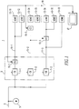
- the conductors 3 and 11 are all represented by a single line for simplicity, but it should be understood that all of these conductors can be multiphase as explicitly shown below.
- an individual monitoring unit 15-1 to 15-3 is placed on the conductors 11-1 to 11-3 for each of the loads 13-11 to 13-33.
- these monitoring units 15-1 to 15-3 can be placed anywhere in the distribution system, including anywhere along the conductors 11-1 to 11-3, because unlike the earlier monitoring units described in the above-referenced U.S. patent applications, and U.S. patent number 5,315,531 the monitoring units 15-1 to 15-3 do not have to be mounted directly on the circuit breakers 7-1 to 7-3.
Abstract
Description
- U.S. patent application 07/746,018 filed on August 15, 1991 for Energy Monitoring System for a Plurality of Local Stations with Snapshot Polling from a Central Station.
- U.S. patent application 08/185,668, filed on January 21, 1994,y for Energy Monitoring System for a Plurality of Local Stations with Snapshot Polling from a Central Station which is a division of 07/746,018.
- This invention relates to monitoring current and voltage in branches of an ac electrical power distribution system, and more particularly to apparatus which can be locked to the conductors of the ac distribution system at any location along the conductors.
- The above-referenced related applications and U.S. patent number 5,315,531 disclose a system for monitoring the energy consumed at multiple locations below the electric meter which is typically installed by a utility on the main power lines serving a customer. This system allows the customer to determine consumption for each location below the meter and allocate costs accordingly, if desired.
- The energy monitoring system includes a modular unit at each location to be monitored. Each modular unit has a toroidal coil inductively coupled to each phase conductor of the ac distribution system by passing the conductor through the coil. The coils are mounted in a housing having through passages extending through the toroidal coils so that the conductors pass completely through the housing. Stabs extending from the housing adjacent the through passages engage the terminals on a circuit breaker together with the ac conductors to provide a voltage pick-up for the unit and to secure the unit to the circuit breaker. Thus, these units are referred to as piggy back units since they are mounted to the circuit breaker.
- The piggy back units include circuitry which digitizes the analog currents and voltages sensed by the toroidal coils and the stabs, respectively, and calculates power and energy consumed utilizing an on board microprocessor. The energy monitoring system also includes a central, personal computer (PC) which is linked to each of the piggy back units by a simple two-wire synchronous communication line daisy chained between the units and the PC. The PC gathers the calculations generated by each of the local units for use in allocating billing.
- The piggy back units are dimensioned to match the dimensions of the circuit breaker and can be secured to the circuit breakers mounted in a load center without requiring modifications to either the circuit breaker or the load center. There is a need; however, to be able to tap the monitoring units into the power distribution system at locations other than at a conductor termination, as is currently required for the voltage stab.
- There is a further need for a monitoring apparatus which can monitor the current and voltage at any point along the conductors of the power distribution system and which does not require stripping of the conductor for the voltage connection.
- There is also a need for such a monitoring apparatus which can lock the monitoring unit simply to any location along the conductor.
- These needs and others are provided by the invention which is directed to apparatus for monitoring current and voltage and for making energy calculations therefrom and which can be locked to any point along the electrical conductors of an ac power distribution system. In particular, the apparatus includes a housing having through passage means extending completely through the housing. A separate through passage is provided for each of the conductors. Combination mounting and voltage sensing means include elongated electrically conductive fastener means extending from the housing laterally into the through passages. These fasteners have pointed ends which pierce insulation on the conductors to electrically contact and mechanically clamp the electrical conductors passing through the passages. The housing includes toroidal coil means, one toroidal coil for each conductor through which the through passages, and therefore, the electrical conductors pass, to inductively sense the currents in the conductors. The housing also includes circuitry connected to the toroidal coils for measuring the currents and connected to the electrically conductive fasteners to measure the voltages. Preferably, this circuitry includes analog to digital converter means for digitizing the analog currents and voltages detected by the toroidal coils and the fasteners, respectively, and digital processing means for calculating energy consumed. Also preferably, the apparatus includes a communications link for communication with a remote control unit.
- The elongated, electrically conductive fasteners are preferably threaded into electrically conductive support blocks recessed in openings in the housing and which are covered with removable electrically insulating closures to protect personnel from contact with the fasteners which are at line voltage.
- An electrically insulating sleeve fills in the through passage around smaller diameter conductors. The pointed ends of the elongated electrically conductive fasteners penetrate this sleeve as well as the insulation on the conductor.
- The invention provides a simple compact monitor which can be easily and quickly installed at any point along the conductors of an ac power distribution system for monitoring current and voltage.
- A full understanding of the invention can be gained from the following description of the preferred embodiments when read in conjunction with the accompanying drawings in which:
- Figure 1 is a schematic diagram of an ac power distribution system to which the invention has been applied.
- Figure 2 is a front elevation view of a monitoring unit in accordance with the invention shown mounted on three phase conductors of the distribution system.
- Figure 3 is a bottom plan view of the monitoring unit of Figure 2.
- Figure 4 is a vertical section view through the monitoring unit taken along the line 4-4 in Figure 2 shown with the conductor removed.
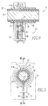
- Figure 5 is a fragmentary view illustrating a combined mount and voltage tap which forms part of the monitoring unit of Figures 2-4 shown mounted on a printed circuit board (PCB) and engaging a conductor of the distribution system.
- Figure 6 is a vertical sectional view through the assembly shown in Figure 5 taken along the line 6-6.
- Figure 7 is a laid open view of the PCBs of the monitoring unit showing the current sensing coils, voltage taps and circuitry mounted thereon.
- Figure 1 illustrates a secondary ac
power distribution system 1 to which the invention has been applied. The secondary acpower distribution system 1 includes a main ac line which provides power generated by the electric utility. The utility places a meter 5 on the main ac line to measure energy consumed by thedistribution system 1. The main ac line 3 is connected to a number of circuit breakers 7-1 to 7-3 mounted in a panel board or load center 9. Each of the circuit breakers 7 provides protection for a circuit which includes aload conductor 11 providing power to a load 13. - The
conductors 3 and 11 are all represented by a single line for simplicity, but it should be understood that all of these conductors can be multiphase as explicitly shown below. In order to be able to monitor the energy consumed by the individual loads 13, an individual monitoring unit 15-1 to 15-3 is placed on the conductors 11-1 to 11-3 for each of the loads 13-11 to 13-33. In accordance with the invention, these monitoring units 15-1 to 15-3 can be placed anywhere in the distribution system, including anywhere along the conductors 11-1 to 11-3, because unlike the earlier monitoring units described in the above-referenced U.S. patent applications, and U.S. patent number 5,315,531 the monitoring units 15-1 to 15-3 do not have to be mounted directly on the circuit breakers 7-1 to 7-3. Thus, as seen in Figure 1, the monitoring unit 15-1 can be placed in the panel board or load center 9 where it monitors energy consumed by all of the loads 13-11 and 13-12 protected by an individual circuit breaker 7-1. On the other hand, where the energy consumed by an individual load such as the load 13-21 is of interest, the monitoring unit 15-2 can be placed adjacent the load. Obviously, the invention provides a great deal of flexibility such that a monitoring unit such as 15-3 can monitor multiple loads 13-31 and 13-32, but not all of the loads (not 13-33) on a particular circuit. - The monitoring units 15-1 to 15-3 monitor the current and voltage, in a manner to be discussed below, in the conductor to which they are coupled and calculate power and energy consumed. Except as described below, the units 15-1 to 15-3 are the same as those desceibed in U.S. patent 5,315,531 which is hereby incorporated by reference. As described in that patent, the individual monitoring units 15-1 to 15-3 are linked to a central unit such as represented by the personal computer (PC) 17 in Figure 1 through a
communications link 19, which in the illustrated embodiment is an INCOM system. The INCOM communications system utilizes a simple two wire synchronous communication line which is daisy chained to the several monitoring units 15-1 to 15-3 and the PC 17. The PC 17 digitally addresses each of the monitoring units 15-1 to 15-3 in a master - slave relationship for the purpose of gathering the data generated by the individual monitoring units for central processing and allocating appropriate portions of the total billing determined by the meter 5 to the local users. - Turning to Figures 2 and 3, the
monitoring units 15 comprise ahousing 21 which includes a moldedcasing 23 with a moldedcover 25. A throughpassage 27A - 27C provided for each phase of theconductor 11 passes completely through thehousing 21. As shown in Figure 4, atubular portion 29 of thecasing 23 and a matingtubular portion 31 of thecover 25 form the through passages 27. Atoroidal coil 33A to 33C is mounted within thehousing 21 concentric with each of thethrough passages 27A - 27C. Thesetoroidal coils 33A - 33C are mounted on a printed circuit board (PCB) 35. A combined mount andvoltage tap 37 as best seen in Figures 5 and 6, comprises an electricallyconductive support block 39 which is pinned or soldered to asecond PCB 41 havingopenings support block 39 has a threaded throughbore 43. An elongated threadedfastener 45 is threaded into the threaded bore 43 and extends generally radially into the associated through passage 27. The elongated threadedfastener 45 has a sharpenedpoint 47. Both thefastener 45 and thesupport block 39 are preferably made of copper plated with silver for good electrical conductivity. - As shown in Figures 4-6, the
phase conductors 11 for the load to be monitored are passed through the throughpassages 27A-27C. And thus through thetoroidal coils 33A-33C which inductively sense the current flowing in the conductors. Eachelongated fastener 45 which is slotted at 49 is accessible through anopening 51 in thehousing 21. A screw driver engages theslot 49 to thread the fastener through theblock 39 into thepassage 27A-27C. Thepointed end 47 of thefastener 45 penetrates theinsulation 53 on theconductor 11 and theconducting wire 55 to thus make electrical contact with thewire 55.Fastener 45 also mechanically clamps theconductor 11 within the through passage 27 to thereby lock themonitoring unit 15 to the conductor. Normally thepassage 51 is plugged with an insulatingplastic plug 57 to prevent an inadvertent contact with thefastener 45 which is at line potential. - The through passages 27 are sized to accommodate various size conductors. For conductors smaller than the maximum size that can be accommodated, an insulating
sleeve 59 is provided which allows the smaller conductor to be clamped with its axis concentric with that of the toroidal coil 33. (See Figure 3). Thepointed end 45 also penetrates thissleeve 59. - As seen in Figure 7, the electrically conductive support blocks 39 are connected by
resistors 61 toPCB 35 on which thecoils 33A-33C are mounted on thePCB 41. As described in detail in patent number 5,315,531, the analog voltage signals derived by the combined mount and voltage taps 37, and the analog current signals generated by the toroidal coils 33, are transferred byribbon connector 63 toPCB 41 where they are converted to digital signals for calculation of the energy consumed by circuits identified generally by thereference character 65. Thecircuitry 65 can include the custom Sure Plus integrated circuit chip (IC) described in U.S. patent number 5,270,898 which is hereby incorporated by reference. This IC includes an analog to digital converter, a microprocessor and a communications interface by which the calculated energy consumed is provided to the communications link 19 through aconnector 67 in thehousing 21.
While specific embodiments of the invention have been described in detail, it will be appreciated by those skilled in the art that various modifications and alternatives to those details could be developed in light of the overall teachings of the disclosure. Accordingly, the particular arrangements disclosed are meant to be illustrative only and not limiting as to the scope of invention which is to be given the full breadth of the claims appended and any and all equivalents thereof.
Claims (5)
- Apparatus (15) for monitoring voltage and current anywhere along electrical conductor means (11) covered with electrical insulation (53) in an ac power distribution system (1), said apparatus comprising:
a housing (21) having through passage means through (27) which said conductor means (11) passes completely through said housing;
combined mounting and voltage tap means (37) comprising elongated electrically conductive fastener means (45) extending from said housing (21) laterally into said through passage means (27) and having a pointed end (47) which penetrates said electrical insulation (53) covering said electrical conductor means (11) and electrically contacts and mechanically clamps said electrical conductor means (11) in said through passage means (27) to lock said housing (21) on said electrical conductor means (11);
toroidal coil means (33) within said housing (21) and through which said through passage means (27) and said electrical conductor means (11) extend for sensing current flowing through said electrical conductor means (11); and
circuit means (65) within said housing (21) connected to said toroidal coil means (33) for monitoring current flowing in said electrical conductor means (11) and connected to said electrically conductive fastener means (45) for measuring voltage on said electrical conductor means (11). - The apparatus (15) of Claim 1 wherein said combined mounting and voltage tap means (37) further includes electrically insulating sleeve means (59) in said through passage means (27) and through which said electrical conductor means (11) extends, said elongated electrically conductive fastener means (45) piercing and extending through said electrically insulating sleeve means (59).
- The apparatus (15) of Claim 1 wherein said ac power distribution system (1) is a multiphase ac system comprising a plurality of electrical conductors (11) each covered with electrical insulation (53), wherein said through passage means (27) comprises a circular through passage (27A-C) through said housing for each of said electrical conductors, wherein said elongated electrically conductive fastener means (45) comprises an elongated electrically conductive fastener (45A-C) extending from said housing (21) substantially radially into each of said circular through passages (27A-C), piercing the electrical insulation (53) on an electrical conductor (11) extending through said circular through passage and electrically contacting and mechanically clamping said electrical conductor (11) in said through passage to lock said housing on said conductors, and wherein said toroidal coil means (33) comprises a separate toroidal coil (33A-C) through which each of said through passages (27A-C) extends, wherein said circuit means (65) is connected to each toroidal coil (33A-C) for measuring current in each electrical conductor and is connected to each of said elongated electrically conductive fasteners (45A-C) for measuring voltages on said electrical conductors (11).
- The apparatus (15) of Claim 3 wherein said housing (21) has electrically conductive support blocks (39A-C) with threaded bores (43) aligned substantially radially with each of said through passages (27A-C), wherein said elongated electrically conductive fasteners (45A-C) comprise pointed screws threaded into said threaded bores (43) and extending substantially radially into said through passages (27A-C), and wherein said circuit means (65) is connected to said elongated electrically conductive fasteners (45A-C) through said electrically conductive support blocks (39A-C).
- The apparatus (15) of Claim 4 wherein said support blocks (39A-C) are recessed in said housing (21), said fasteners (45A-C) threaded into said support blocks (39A-C) being accessible through openings (51) in said housing (21) and said housing further having electrically insulating removable closures (57) closing said openings (51).
Applications Claiming Priority (2)
| Application Number | Priority Date | Filing Date | Title |
|---|---|---|---|
| US262166 | 1994-06-20 | ||
| US08/262,166 US5548523A (en) | 1994-06-20 | 1994-06-20 | Monitoring device secured to power distribution system conductors |
Publications (3)
| Publication Number | Publication Date |
|---|---|
| EP0689057A2 true EP0689057A2 (en) | 1995-12-27 |
| EP0689057A3 EP0689057A3 (en) | 1997-01-08 |
| EP0689057B1 EP0689057B1 (en) | 2004-06-02 |
Family
ID=22996436
Family Applications (1)
| Application Number | Title | Priority Date | Filing Date |
|---|---|---|---|
| EP95109111A Expired - Lifetime EP0689057B1 (en) | 1994-06-20 | 1995-06-13 | Monitoring device secured to power distribution system conductors |
Country Status (10)
| Country | Link |
|---|---|
| US (1) | US5548523A (en) |
| EP (1) | EP0689057B1 (en) |
| JP (1) | JPH0815334A (en) |
| CN (1) | CN1105307C (en) |
| BR (1) | BR9502253A (en) |
| CA (1) | CA2152220C (en) |
| DE (1) | DE69533098T2 (en) |
| NZ (1) | NZ272152A (en) |
| PH (1) | PH30707A (en) |
| ZA (1) | ZA954944B (en) |
Cited By (9)
| Publication number | Priority date | Publication date | Assignee | Title |
|---|---|---|---|---|
| WO2000004392A1 (en) * | 1998-07-17 | 2000-01-27 | Honeywell Limited | An electrical supply measurement and management system |
| WO2000045183A2 (en) * | 1999-01-29 | 2000-08-03 | Suparules Limited | Electrical energy meter |
| WO2008144161A1 (en) * | 2007-05-16 | 2008-11-27 | Square D Company | Clamp-on current and voltage module for a power monitoring system |
| EP1887366A3 (en) * | 2006-08-03 | 2012-01-04 | The Boeing Company | Method and system for measurement of current flows in fastener arrays |
| EP2402769A1 (en) * | 2010-06-30 | 2012-01-04 | ABB Technology AG | Combined detection device for electrical variables |
| WO2014182425A1 (en) * | 2013-05-07 | 2014-11-13 | Eaton Corporation | Load panel branch circuit monitor employing an intelligent current sensor module |
| WO2015197911A1 (en) * | 2014-06-27 | 2015-12-30 | Efore Oyj | An electrical energy meter and a method for installing it |
| EP2506020A3 (en) * | 2011-04-01 | 2017-07-26 | Bender GmbH & Co. KG | Device for measuring currents in electricity supply networks |
| WO2017160254A1 (en) * | 2016-03-15 | 2017-09-21 | Luna Elektrik Elektronik Sanayi Ve Ticaret A. S. | Electric meter and/or electric measuring instrument without connection terminals comprising cable passage |
Families Citing this family (23)
| Publication number | Priority date | Publication date | Assignee | Title |
|---|---|---|---|---|
| US6191697B1 (en) | 1999-04-19 | 2001-02-20 | International Business Machines Corporation | Circuit continuity detection system and method |
| US6901432B2 (en) * | 2001-11-27 | 2005-05-31 | Eaton Corporation | Translator apparatus for two communication networks |
| DE10223370A1 (en) * | 2002-05-25 | 2003-12-04 | Bosch Gmbh Robert | Electronic device with a housing |
| US20050273531A1 (en) * | 2004-06-07 | 2005-12-08 | Domitrovich Thomas A | Display device including two communication ports and display system including same |
| US20060224711A1 (en) * | 2005-03-29 | 2006-10-05 | Eaton Corporation | Self-learning server communicating values from a plurality of communicating devices of one communication network to a client of another communication network |
| US7280338B2 (en) * | 2005-05-12 | 2007-10-09 | Eaton Corporation | Power supply circuit, back-pack power supply module and circuit interrupter including the same |
| US20070086133A1 (en) * | 2005-10-18 | 2007-04-19 | Eaton Corporation | Network system for safe connection of generation into a network power system |
| US20070249319A1 (en) * | 2006-04-24 | 2007-10-25 | Faulkner Mark A | Power distribution communication system employing gateway including wired and wireless communication interfaces |
| ITPD20070121A1 (en) * | 2007-04-02 | 2008-10-03 | Mario Berton | MEASUREMENT DEVICE FOR ELECTRICAL QUANTITIES FOR ENERGY TRANSPORT LINES |
| US20080192812A1 (en) * | 2007-02-09 | 2008-08-14 | Marco Naeve | Wireless communication adapter for a programmable logic controller and programmable logic controller system including the same |
| US20090291680A1 (en) * | 2008-05-23 | 2009-11-26 | Mort Deborah K | Wireless communication network and wireless control or monitoring device employing an xml schema |
| CN101634664B (en) * | 2009-08-18 | 2011-06-29 | 宁波汉克电器有限公司 | Electric energy meter |
| US8493012B2 (en) * | 2009-11-17 | 2013-07-23 | Eaton Corporation | Protection relay, electrical switching apparatus, and system for determining and outputting fault current available at a load and incident energy or personal protective equipment level operatively associated therewith |
| US8654496B2 (en) | 2011-05-13 | 2014-02-18 | Eaton Corporation | Trip unit including separable component to save and restore settings, and circuit breaker including the same |
| US8649147B2 (en) | 2011-12-13 | 2014-02-11 | Eaton Corporation | Trip unit communication adapter module employing communication protocol to communicate with different trip unit styles, and electrical switching apparatus and communication method employing the same |
| FR2998674B1 (en) * | 2012-11-28 | 2015-07-17 | Schneider Electric Ind Sas | DEVICE FOR MEASURING AT LEAST ONE ELECTRICAL SIZE OF A CURRENT CIRCULATING IN AN ELECTRICAL APPARATUS |
| US20140210455A1 (en) * | 2013-01-28 | 2014-07-31 | Marvin Dee Allgood | Voltage tap device |
| CN103595301B (en) * | 2013-11-22 | 2015-07-15 | 湖北工业大学 | Magnetic force suspension robot for operation of overhead high-tension power transmission line |
| CN103595300B (en) * | 2013-11-22 | 2015-09-02 | 湖北工业大学 | A kind of magnetic force drive robot for overhead high-tension transmission line operation |
| GB201404181D0 (en) * | 2014-03-10 | 2014-04-23 | Repl Internat Ltd | Electrical sensor |
| US10794736B2 (en) * | 2018-03-15 | 2020-10-06 | Rosemount Inc. | Elimination of floating potential when mounting wireless sensors to insulated conductors |
| US11177585B2 (en) | 2019-03-15 | 2021-11-16 | Panduit Corp. | Insulation piercing electrical tap connectors |
| US11342728B2 (en) | 2019-12-20 | 2022-05-24 | Eaton Intelligent Power Limited | Circuit interrupters with electronically controlled lock out tag out systems and related electrical distribution systems and methods |
Citations (2)
| Publication number | Priority date | Publication date | Assignee | Title |
|---|---|---|---|---|
| US5270898A (en) | 1990-12-28 | 1993-12-14 | Westinghouse Electric Corp. | Sure chip plus |
| US5315531A (en) | 1991-08-15 | 1994-05-24 | Westinghouse Electric Corp. | Energy monitoring system for a plurality of local stations with snapshot polling from a central station |
Family Cites Families (6)
| Publication number | Priority date | Publication date | Assignee | Title |
|---|---|---|---|---|
| US698218A (en) * | 1902-01-16 | 1902-04-22 | Norden Bittner Electric Company | Electric-lamp socket. |
| FR829353A (en) * | 1937-02-19 | 1938-06-24 | Device for troubleshooting electrical lines or their devices | |
| US2714196A (en) * | 1953-03-16 | 1955-07-26 | George M Melehan | Self-holding tool for testing electric circuits |
| ES2127204T3 (en) * | 1991-08-15 | 1999-04-16 | Eaton Corp | SYSTEM OF VERIFICATION OF THE ENERGY OF A SERIES OF LOCAL STATIONS BY INSTANT SURVEY FROM A CENTRAL STATION. |
| US5384712A (en) * | 1991-08-15 | 1995-01-24 | Eaton Corporation | Energy monitoring system for a plurality of local stations with snapshot polling from a central station |
| US5426360A (en) * | 1994-02-17 | 1995-06-20 | Niagara Mohawk Power Corporation | Secondary electrical power line parameter monitoring apparatus and system |
-
1994
- 1994-06-20 US US08/262,166 patent/US5548523A/en not_active Expired - Lifetime
-
1995
- 1995-05-18 NZ NZ272152A patent/NZ272152A/en unknown
- 1995-05-31 PH PH50630A patent/PH30707A/en unknown
- 1995-06-13 DE DE69533098T patent/DE69533098T2/en not_active Expired - Lifetime
- 1995-06-13 EP EP95109111A patent/EP0689057B1/en not_active Expired - Lifetime
- 1995-06-14 ZA ZA954944A patent/ZA954944B/en unknown
- 1995-06-17 JP JP17400595A patent/JPH0815334A/en active Pending
- 1995-06-19 CN CN95107382A patent/CN1105307C/en not_active Expired - Fee Related
- 1995-06-20 BR BR9502253A patent/BR9502253A/en not_active IP Right Cessation
- 1995-06-20 CA CA002152220A patent/CA2152220C/en not_active Expired - Fee Related
Patent Citations (2)
| Publication number | Priority date | Publication date | Assignee | Title |
|---|---|---|---|---|
| US5270898A (en) | 1990-12-28 | 1993-12-14 | Westinghouse Electric Corp. | Sure chip plus |
| US5315531A (en) | 1991-08-15 | 1994-05-24 | Westinghouse Electric Corp. | Energy monitoring system for a plurality of local stations with snapshot polling from a central station |
Cited By (12)
| Publication number | Priority date | Publication date | Assignee | Title |
|---|---|---|---|---|
| WO2000004392A1 (en) * | 1998-07-17 | 2000-01-27 | Honeywell Limited | An electrical supply measurement and management system |
| WO2000045183A2 (en) * | 1999-01-29 | 2000-08-03 | Suparules Limited | Electrical energy meter |
| WO2000045183A3 (en) * | 1999-01-29 | 2000-12-14 | Suparules Ltd | Electrical energy meter |
| US6825650B1 (en) | 1999-01-29 | 2004-11-30 | Suparules Limited | Current measuring probe and electrical energy meter for use therewith |
| EP1887366A3 (en) * | 2006-08-03 | 2012-01-04 | The Boeing Company | Method and system for measurement of current flows in fastener arrays |
| WO2008144161A1 (en) * | 2007-05-16 | 2008-11-27 | Square D Company | Clamp-on current and voltage module for a power monitoring system |
| EP2402769A1 (en) * | 2010-06-30 | 2012-01-04 | ABB Technology AG | Combined detection device for electrical variables |
| EP2506020A3 (en) * | 2011-04-01 | 2017-07-26 | Bender GmbH & Co. KG | Device for measuring currents in electricity supply networks |
| WO2014182425A1 (en) * | 2013-05-07 | 2014-11-13 | Eaton Corporation | Load panel branch circuit monitor employing an intelligent current sensor module |
| WO2015197911A1 (en) * | 2014-06-27 | 2015-12-30 | Efore Oyj | An electrical energy meter and a method for installing it |
| EP2960659A1 (en) * | 2014-06-27 | 2015-12-30 | Efore OYJ | An electrical energy meter and a method for installing it |
| WO2017160254A1 (en) * | 2016-03-15 | 2017-09-21 | Luna Elektrik Elektronik Sanayi Ve Ticaret A. S. | Electric meter and/or electric measuring instrument without connection terminals comprising cable passage |
Also Published As
| Publication number | Publication date |
|---|---|
| ZA954944B (en) | 1996-02-07 |
| DE69533098T2 (en) | 2005-07-07 |
| BR9502253A (en) | 1996-01-23 |
| US5548523A (en) | 1996-08-20 |
| CA2152220C (en) | 2000-08-29 |
| DE69533098D1 (en) | 2004-07-08 |
| NZ272152A (en) | 1997-04-24 |
| CA2152220A1 (en) | 1995-12-21 |
| CN1105307C (en) | 2003-04-09 |
| AU2028195A (en) | 1996-01-04 |
| AU683736B2 (en) | 1997-11-20 |
| PH30707A (en) | 1997-09-16 |
| EP0689057A3 (en) | 1997-01-08 |
| CN1126852A (en) | 1996-07-17 |
| EP0689057B1 (en) | 2004-06-02 |
| JPH0815334A (en) | 1996-01-19 |
Similar Documents
| Publication | Publication Date | Title |
|---|---|---|
| EP0689057B1 (en) | Monitoring device secured to power distribution system conductors | |
| CN102640366B (en) | Apparatus and method for scalable power distribution | |
| CA2300522C (en) | Revenue meter bayonet assembly and method of attachment | |
| US7453684B2 (en) | Current inputs interface for an electrical device | |
| US11109504B2 (en) | Power distribution unit with interior busbars | |
| EP3367111A1 (en) | Energy metering system | |
| KR20100023043A (en) | Transformer meter and system for using same | |
| US7252543B2 (en) | Methods and systems for measuring system loads and sub-metering electric power distribution | |
| EP3940395A1 (en) | Monitoring system | |
| EP1110097B1 (en) | Terminator unit for wiring networks | |
| US10663530B2 (en) | Test switch assembly having an electronic circuit | |
| JP5224766B2 (en) | Wattmeter connection adapter and wattmeter replacement work method | |
| WO1998027625A1 (en) | Telephone adaptor | |
| CN110031673B (en) | Energy metering for buildings | |
| KR20030065447A (en) | No Connection Type Electronic Watthour Meter | |
| CN219627431U (en) | Power distribution equipment | |
| WO2020013826A1 (en) | Test switch assembly having an electronic circuit | |
| CN220066319U (en) | Inlet wire plug assembly of intelligent switch cabinet | |
| KR200332001Y1 (en) | No Connection Type Electronic Watthour Meter | |
| US6538421B1 (en) | Apparatus with separated conductors | |
| CN214312915U (en) | Miniature opening current transformer is with electric wire protection device with temperature measurement function | |
| CN117406143A (en) | Intelligent connector monitoring device | |
| CN115133297A (en) | Connecting terminal for mounting on supporting guide rail | |
| CN1289046A (en) | Method of installing an on-off and control treatment unit on electric power meter | |
| JPH0797510B2 (en) | Electronics |
Legal Events
| Date | Code | Title | Description |
|---|---|---|---|
| PUAI | Public reference made under article 153(3) epc to a published international application that has entered the european phase |
Free format text: ORIGINAL CODE: 0009012 |
|
| AK | Designated contracting states |
Kind code of ref document: A2 Designated state(s): DE FR GB IE IT SE |
|
| PUAL | Search report despatched |
Free format text: ORIGINAL CODE: 0009013 |
|
| AK | Designated contracting states |
Kind code of ref document: A3 Designated state(s): DE FR GB IE IT SE |
|
| 17P | Request for examination filed |
Effective date: 19970707 |
|
| GRAP | Despatch of communication of intention to grant a patent |
Free format text: ORIGINAL CODE: EPIDOSNIGR1 |
|
| GRAS | Grant fee paid |
Free format text: ORIGINAL CODE: EPIDOSNIGR3 |
|
| GRAA | (expected) grant |
Free format text: ORIGINAL CODE: 0009210 |
|
| AK | Designated contracting states |
Kind code of ref document: B1 Designated state(s): DE FR GB IE IT SE |
|
| REG | Reference to a national code |
Ref country code: GB Ref legal event code: FG4D |
|
| PG25 | Lapsed in a contracting state [announced via postgrant information from national office to epo] |
Ref country code: IE Free format text: LAPSE BECAUSE OF NON-PAYMENT OF DUE FEES Effective date: 20040614 |
|
| REF | Corresponds to: |
Ref document number: 69533098 Country of ref document: DE Date of ref document: 20040708 Kind code of ref document: P |
|
| REG | Reference to a national code |
Ref country code: IE Ref legal event code: FG4D |
|
| REG | Reference to a national code |
Ref country code: SE Ref legal event code: TRGR |
|
| ET | Fr: translation filed | ||
| REG | Reference to a national code |
Ref country code: IE Ref legal event code: MM4A |
|
| PLBE | No opposition filed within time limit |
Free format text: ORIGINAL CODE: 0009261 |
|
| STAA | Information on the status of an ep patent application or granted ep patent |
Free format text: STATUS: NO OPPOSITION FILED WITHIN TIME LIMIT |
|
| 26N | No opposition filed |
Effective date: 20050303 |
|
| PGFP | Annual fee paid to national office [announced via postgrant information from national office to epo] |
Ref country code: IT Payment date: 20070619 Year of fee payment: 13 |
|
| PG25 | Lapsed in a contracting state [announced via postgrant information from national office to epo] |
Ref country code: IT Free format text: LAPSE BECAUSE OF NON-PAYMENT OF DUE FEES Effective date: 20080613 |
|
| PGFP | Annual fee paid to national office [announced via postgrant information from national office to epo] |
Ref country code: SE Payment date: 20120607 Year of fee payment: 18 Ref country code: GB Payment date: 20120525 Year of fee payment: 18 |
|
| PGFP | Annual fee paid to national office [announced via postgrant information from national office to epo] |
Ref country code: FR Payment date: 20130618 Year of fee payment: 19 |
|
| PGFP | Annual fee paid to national office [announced via postgrant information from national office to epo] |
Ref country code: DE Payment date: 20130628 Year of fee payment: 19 |
|
| PG25 | Lapsed in a contracting state [announced via postgrant information from national office to epo] |
Ref country code: SE Free format text: LAPSE BECAUSE OF NON-PAYMENT OF DUE FEES Effective date: 20130614 |
|
| REG | Reference to a national code |
Ref country code: SE Ref legal event code: EUG |
|
| GBPC | Gb: european patent ceased through non-payment of renewal fee |
Effective date: 20130613 |
|
| PG25 | Lapsed in a contracting state [announced via postgrant information from national office to epo] |
Ref country code: GB Free format text: LAPSE BECAUSE OF NON-PAYMENT OF DUE FEES Effective date: 20130613 |
|
| REG | Reference to a national code |
Ref country code: DE Ref legal event code: R119 Ref document number: 69533098 Country of ref document: DE |
|
| REG | Reference to a national code |
Ref country code: FR Ref legal event code: ST Effective date: 20150227 |
|
| REG | Reference to a national code |
Ref country code: DE Ref legal event code: R119 Ref document number: 69533098 Country of ref document: DE Effective date: 20150101 |
|
| PG25 | Lapsed in a contracting state [announced via postgrant information from national office to epo] |
Ref country code: DE Free format text: LAPSE BECAUSE OF NON-PAYMENT OF DUE FEES Effective date: 20150101 |
|
| PG25 | Lapsed in a contracting state [announced via postgrant information from national office to epo] |
Ref country code: FR Free format text: LAPSE BECAUSE OF NON-PAYMENT OF DUE FEES Effective date: 20140630 |