EP0687870A1 - Heat exchanger - Google Patents
Heat exchanger Download PDFInfo
- Publication number
- EP0687870A1 EP0687870A1 EP95201595A EP95201595A EP0687870A1 EP 0687870 A1 EP0687870 A1 EP 0687870A1 EP 95201595 A EP95201595 A EP 95201595A EP 95201595 A EP95201595 A EP 95201595A EP 0687870 A1 EP0687870 A1 EP 0687870A1
- Authority
- EP
- European Patent Office
- Prior art keywords
- pipes
- heat exchanger
- burner
- end plates
- space
- Prior art date
- Legal status (The legal status is an assumption and is not a legal conclusion. Google has not performed a legal analysis and makes no representation as to the accuracy of the status listed.)
- Granted
Links
- 239000003546 flue gas Substances 0.000 claims abstract description 17
- 239000007788 liquid Substances 0.000 claims abstract description 12
- 229910001220 stainless steel Inorganic materials 0.000 claims abstract description 10
- 239000010935 stainless steel Substances 0.000 claims abstract description 10
- 239000002184 metal Substances 0.000 claims abstract description 3
- 229910052751 metal Inorganic materials 0.000 claims abstract description 3
- 238000009833 condensation Methods 0.000 claims description 8
- 230000005494 condensation Effects 0.000 claims description 8
- 238000001816 cooling Methods 0.000 claims description 8
- 239000007789 gas Substances 0.000 claims description 6
- 238000005476 soldering Methods 0.000 claims description 5
- 230000005855 radiation Effects 0.000 claims description 3
- 230000008878 coupling Effects 0.000 claims description 2
- 238000010168 coupling process Methods 0.000 claims description 2
- 238000005859 coupling reaction Methods 0.000 claims description 2
- 230000001681 protective effect Effects 0.000 claims description 2
- 238000003466 welding Methods 0.000 claims description 2
- 238000006243 chemical reaction Methods 0.000 description 5
- UGFAIRIUMAVXCW-UHFFFAOYSA-N Carbon monoxide Chemical compound [O+]#[C-] UGFAIRIUMAVXCW-UHFFFAOYSA-N 0.000 description 3
- 239000000463 material Substances 0.000 description 3
- 239000000567 combustion gas Substances 0.000 description 2
- 238000000926 separation method Methods 0.000 description 2
- 238000002485 combustion reaction Methods 0.000 description 1
- 239000000470 constituent Substances 0.000 description 1
- 230000000694 effects Effects 0.000 description 1
- 230000002349 favourable effect Effects 0.000 description 1
- 239000000446 fuel Substances 0.000 description 1
- 238000010438 heat treatment Methods 0.000 description 1
- 238000004519 manufacturing process Methods 0.000 description 1
- 238000000034 method Methods 0.000 description 1
- 238000013022 venting Methods 0.000 description 1
- XLYOFNOQVPJJNP-UHFFFAOYSA-N water Substances O XLYOFNOQVPJJNP-UHFFFAOYSA-N 0.000 description 1
Images

Classifications
-
- F—MECHANICAL ENGINEERING; LIGHTING; HEATING; WEAPONS; BLASTING
- F28—HEAT EXCHANGE IN GENERAL
- F28D—HEAT-EXCHANGE APPARATUS, NOT PROVIDED FOR IN ANOTHER SUBCLASS, IN WHICH THE HEAT-EXCHANGE MEDIA DO NOT COME INTO DIRECT CONTACT
- F28D7/00—Heat-exchange apparatus having stationary tubular conduit assemblies for both heat-exchange media, the media being in contact with different sides of a conduit wall
- F28D7/0041—Heat-exchange apparatus having stationary tubular conduit assemblies for both heat-exchange media, the media being in contact with different sides of a conduit wall the conduits for only one medium being tubes having parts touching each other or tubes assembled in panel form
-
- F—MECHANICAL ENGINEERING; LIGHTING; HEATING; WEAPONS; BLASTING
- F24—HEATING; RANGES; VENTILATING
- F24H—FLUID HEATERS, e.g. WATER OR AIR HEATERS, HAVING HEAT-GENERATING MEANS, e.g. HEAT PUMPS, IN GENERAL
- F24H1/00—Water heaters, e.g. boilers, continuous-flow heaters or water-storage heaters
- F24H1/22—Water heaters other than continuous-flow or water-storage heaters, e.g. water heaters for central heating
- F24H1/40—Water heaters other than continuous-flow or water-storage heaters, e.g. water heaters for central heating with water tube or tubes
-
- F—MECHANICAL ENGINEERING; LIGHTING; HEATING; WEAPONS; BLASTING
- F24—HEATING; RANGES; VENTILATING
- F24H—FLUID HEATERS, e.g. WATER OR AIR HEATERS, HAVING HEAT-GENERATING MEANS, e.g. HEAT PUMPS, IN GENERAL
- F24H8/00—Fluid heaters characterised by means for extracting latent heat from flue gases by means of condensation
-
- F—MECHANICAL ENGINEERING; LIGHTING; HEATING; WEAPONS; BLASTING
- F28—HEAT EXCHANGE IN GENERAL
- F28F—DETAILS OF HEAT-EXCHANGE AND HEAT-TRANSFER APPARATUS, OF GENERAL APPLICATION
- F28F2210/00—Heat exchange conduits
- F28F2210/08—Assemblies of conduits having different features
-
- Y—GENERAL TAGGING OF NEW TECHNOLOGICAL DEVELOPMENTS; GENERAL TAGGING OF CROSS-SECTIONAL TECHNOLOGIES SPANNING OVER SEVERAL SECTIONS OF THE IPC; TECHNICAL SUBJECTS COVERED BY FORMER USPC CROSS-REFERENCE ART COLLECTIONS [XRACs] AND DIGESTS
- Y02—TECHNOLOGIES OR APPLICATIONS FOR MITIGATION OR ADAPTATION AGAINST CLIMATE CHANGE
- Y02B—CLIMATE CHANGE MITIGATION TECHNOLOGIES RELATED TO BUILDINGS, e.g. HOUSING, HOUSE APPLIANCES OR RELATED END-USER APPLICATIONS
- Y02B30/00—Energy efficient heating, ventilation or air conditioning [HVAC]
Definitions
- the invention relates to a heat exchanger.
- Heat exchangers are known in different embodiments. Even for the same application the design of a heat exchanger can be very different.
- a further object of the invention is to design a heat exchanger such that it can be manufactured at relatively low cost, while the reliability and life-span nevertheless meet very high standards.
- the invention provides a heat exchanger, comprising: a plurality of substantially mutually parallel metal pipes through which liquid can flow; a space at least partially bounded by these pipes in which a burner can be accommodated such that the heat coming from the burner can heat via the walls of the pipes the liquid flowing therethrough; which pipes are fixed with their ends in stainless steel end plates which are provided with holes into which the pipes fit, which holes are ordered in a predetermined pattern; which end plates co-act sealingly with respective end walls which together with these end plates form compartments through which the liquid flowing through the pipes can flow; between which end plates at least one closed side wall extends which forms a side boundary of the space in which the pipes are situated while leaving free the said space for the burner and an outlet space situated on the other side of the pipes which connects to an outlet for flue gases; which pipes are of stainless steel with a wall thickness of (0.5 ⁇ 0.2) mm and are ordered in a pattern such that in a region through which the flue gases flow they have mutual distances of (1.0 ⁇ 0.5
- the heat exchanger can for example have a more or less cylindrical structure, wherein a central burner space is surrounded by a pattern of pipes lying at a mutual distance. Around these pipes extends a closed wall in order to prevent the uncontrolled escape of flue gases other than through the outlet intended for this purpose.
- the heat exchanger is embodied such that the pipes bound a more or less trough-shaped space, in which the burner can be accommodated.
- the flue gases are guided through a plurality of pipes placed at a mutual distance for feeding to the outlet, which connects in gastight manner to, in this case, two side walls and to the end plates.
- the structure according to the invention offers a very favourable compromise between heat conduction, pressure resistance and the price of the heat exchanger.
- a heat exchanger according to the invention can advantageously display the special feature that the end zones of the pipes supported by the end plates have a reduced outer diameter.
- the amount of material of the end walls between the holes accommodating the pipes is greater than between the pipes. This is advantageous from the viewpoint of production technique and moreover provides an increased mechanical strength.
- the heat exchanger according to the invention has a certain flow resistance against the heat-bearing combustion gases coming from the burner.
- condensation is collected in the spaces between the pipes. This results in a considerable increase in the effective flow resistance, possibly even to the extent of a (partial) blockage.
- the heat exchanger according to the invention preferably has the special feature that the pipes bound a space for the burner, which space generally has the shape of a trough open to the top; under the heat exchanger is arranged a collecting tray for condensation to which an outlet optionally connects; and the heat exchanger is disposed such that the pipes extend at a chosen angle to the horizontal plane. The formed condensation is drained rapidly due to this inclining positioning.
- the said angle has a value of (7 ⁇ 4)°, preferably (7 ⁇ 1)°, a very rapid discharge of condensation takes place and there is no measurable difference between the said flow resistance during "dry” operation and "wet” operation.
- a very advantageous embodiment of the heat exchanger according to the invention comprises an arrangement and disposition of the pipes such that the hot gases coming from the burner are first subjected to a limited cooling through a plurality of pipes of relatively large diameter and relatively large mutual distances, followed by a strong cooling through the said group of pipes of relatively small diameter.
- the heat exchanger comprises a plurality of pipes ordered relative to the burner such that the hot gases generated by the burner can give off their heat via the walls of the pipes to the heat exchanging medium flowing through the pipes, in particular water.
- the heat is created by combusting gaseous fuel with air. The reaction proceeds approximately thus: 2 CH4 + 3 O2 ⁇ 2 CO + 4H2O, followed by 2CO + O2 ⁇ 2 CO2.
- the temperature of the combustion gases is about 1500°C-1800°C immediately after the burner. At this temperature there is a balance between the gaseous components such that a considerable proportion of CO is present. With a temperature reduction CO transposes into CO2. However, when cooling proceeds very rapidly the situation is as it were frozen and a part of the CO cannot continue to react sufficiently in the manner indicated. This CO is then found in the emission of the combustion device. Because of the above described structure according to 6, only a relatively small portion of the heat is extracted in the first instance from the hot flue gases, whereby the reaction can be controlled such that all the CO can be converted into CO2. The flue gas temperature is lowered from 1500-1800°C to 1100°. At this temperature all the CO can be converted into CO2 in the manner indicated.
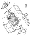
- Figure 1 shows an exploded view of an embodiment of the heat exchanger according to the invention.
- Two stainless steel end plates 1, 2 are provided with holes and thus serve to support the end zones of stainless steel pipes in the shown pattern, which can be seen particularly clearly with reference to the outer side of end plate 1.
- patterns 5, 6, each consisting of a row of pipes 3 soldered to each other Connecting onto the pattern 4 on either side are patterns 5, 6, each consisting of a row of pipes 3 soldered to each other.
- figure 2 shows that the pipes situated in pattern 6 are mutually connected by soldered seams 7. The reason for this mutual connection will be discussed hereinafter.
- end walls 10, 11 connect sealingly to the end plates 1, 2 via seals 8, 9, which end walls together with these end plates 1, 2 bound in the manner shown compartments through which liquid can flow in a pre-selected manner.
- the presence of the soldered seams between the pipes 3 in patterns 5 and 6 ensures that the side walls 12, 13 are shielded against direct radiation heat from the flame generated by the burner.
- the pipes 3 in patterns 5, 6 could also be placed overlapping and staggered, whereby a shade effect would be obtained.
- the mutual connection of pipes 3 and patterns 5, 6 can take place very suitably by vacuum soldering, for example with Ni, Cr, Si at a temperature in the order of 1300°C.
- this inclination can be described as a tilting round a horizontal tilt axis 21 such that the mutually parallel pipes extend at an angle 22 of 7° indicated with a horizontal dashed line 18.
- an effective draining of the condensation accumulating between the pipes 3 takes place in the direction indicated by arrow 19. The condensation is then carried away downward via end plate 1 and collected in tray 14.
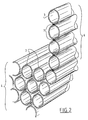
- Figure 3 shows a part of a heat exchanger in a preferred embodiment.
- Two stainless steel end plates 23, 24 are provided with holes and thus serve to support the end zone of stainless steel pipes in the pattern shown in figure 3.
- On the underside is situated a pattern 25 of five layers of pipes which have mutual distances of about 1.0 mm and a wall thickness of 0.5 mm.
- Connecting on either side to the pattern 25 are patterns 26, 27, each consisting of a row of mutually soldered pipes.
- the relatively thin pipes 3 of patterns 25, 26 and 27 bound together with the end plates 23, 24 a trough-shaped space.
- the structure according to figure 3 corresponds with the structure shown in figure 1, apart from the plurality of layers of pipes 3 in pattern 25.
- the unit 28 according to figure 3 has a plurality of additional pipes 29 of relatively large diameter.
- a first relatively slight cooling of the flue gases takes place, followed by a subsequent cooling through two rows of pipes 29 located lower down and mutually staggered, where a further cooling takes place. It is particularly in the space between the upper and the subsequent row of pipes 29 where the reaction of CO to CO2 can take place. The distance between these rows of pipes provides the time for the necessary shift in the balance to take place.
Landscapes
- Engineering & Computer Science (AREA)
- Physics & Mathematics (AREA)
- Thermal Sciences (AREA)
- Mechanical Engineering (AREA)
- General Engineering & Computer Science (AREA)
- Chemical & Material Sciences (AREA)
- Combustion & Propulsion (AREA)
- Heat-Exchange Devices With Radiators And Conduit Assemblies (AREA)
- Power Steering Mechanism (AREA)
- Compression-Type Refrigeration Machines With Reversible Cycles (AREA)
- Separation By Low-Temperature Treatments (AREA)
Abstract
a plurality of substantially mutually parallel metal pipes (3) through which liquid can flow;
a space at least partially bounded by these pipes (3) in which a burner can be accommodated such that the heat coming from the burner can heat via the walls of the pipes the liquid flowing therethrough;
which pipes are fixed with their ends in stainless steel end plates (1,2) which are provided with holes into which the pipes fit, which holes are ordered in a predetermined pattern;
which end plates (1,2) co-act sealingly with respective end walls (10,11) which together with these end plates (1,2) form compartments through which the liquid flowing through the pipes can flow;
between which end plates (1,2) at least one closed side wall (12,13) extends which forms a side boundary of the space in which the pipes are situated while leaving free the said space for the burner and an outlet space situated on the other side of the pipes which connects to an outlet for flue gases;
which pipes are of stainless steel with a wall thickness of (0.5 ± 0.2) mm and are ordered in a pattern such that in a region through which the flue gases flow they have mutual distances of (1.0 ± 0.5) mm.
Description
- The invention relates to a heat exchanger.
- Heat exchangers are known in different embodiments. Even for the same application the design of a heat exchanger can be very different.
- It is an object of the invention to design a heat exchanger such that it consists of few components which are each constructed from a single material, which facilitates re-use.
- A further object of the invention is to design a heat exchanger such that it can be manufactured at relatively low cost, while the reliability and life-span nevertheless meet very high standards.
- In respect of the above the invention provides a heat exchanger, comprising:
a plurality of substantially mutually parallel metal pipes through which liquid can flow;
a space at least partially bounded by these pipes in which a burner can be accommodated such that the heat coming from the burner can heat via the walls of the pipes the liquid flowing therethrough;
which pipes are fixed with their ends in stainless steel end plates which are provided with holes into which the pipes fit, which holes are ordered in a predetermined pattern;
which end plates co-act sealingly with respective end walls which together with these end plates form compartments through which the liquid flowing through the pipes can flow;
between which end plates at least one closed side wall extends which forms a side boundary of the space in which the pipes are situated while leaving free the said space for the burner and an outlet space situated on the other side of the pipes which connects to an outlet for flue gases;
which pipes are of stainless steel with a wall thickness of (0.5 ± 0.2) mm and are ordered in a pattern such that in a region through which the flue gases flow they have mutual distances of (1.0 ± 0.5) mm and that they shield the side wall from the radiation generated by the burner surface, for example by overlapping and staggered placing, adjacent placing or mutual coupling, for example by welding or soldering, of the relevant pipes placed adjacently of the side wall. - The heat exchanger can for example have a more or less cylindrical structure, wherein a central burner space is surrounded by a pattern of pipes lying at a mutual distance. Around these pipes extends a closed wall in order to prevent the uncontrolled escape of flue gases other than through the outlet intended for this purpose.
- In another embodiment the heat exchanger is embodied such that the pipes bound a more or less trough-shaped space, in which the burner can be accommodated. The flue gases are guided through a plurality of pipes placed at a mutual distance for feeding to the outlet, which connects in gastight manner to, in this case, two side walls and to the end plates.
- It will also be apparent that there must be a strict physical separation between the burner space and the spaces through which the flue gases flow and the spaces through which the liquid for heating flows.
- The structure according to the invention offers a very favourable compromise between heat conduction, pressure resistance and the price of the heat exchanger.
- In order to realise the required mutual distance between at least a number of pipes of (1.0 ± 0.5) mm a heat exchanger according to the invention can advantageously display the special feature that the end zones of the pipes supported by the end plates have a reduced outer diameter. Hereby achieved is that the amount of material of the end walls between the holes accommodating the pipes is greater than between the pipes. This is advantageous from the viewpoint of production technique and moreover provides an increased mechanical strength.
- Very suitable is the embodiment in which the pipes are coupled with their ends to the end plates by high temperature soldering, for instance in vacuum or with a protective gas.
- The heat exchanger according to the invention has a certain flow resistance against the heat-bearing combustion gases coming from the burner. When the exchanger comes into condensing operation, which is aimed for in principle in order to obtain maximum efficiency, condensation is collected in the spaces between the pipes. This results in a considerable increase in the effective flow resistance, possibly even to the extent of a (partial) blockage.
- In this respect the heat exchanger according to the invention preferably has the special feature that the pipes bound a space for the burner, which space generally has the shape of a trough open to the top; under the heat exchanger is arranged a collecting tray for condensation to which an outlet optionally connects; and the heat exchanger is disposed such that the pipes extend at a chosen angle to the horizontal plane. The formed condensation is drained rapidly due to this inclining positioning.
- In an embodiment in which the said angle has a value of (7 ± 4)°, preferably (7 ± 1)°, a very rapid discharge of condensation takes place and there is no measurable difference between the said flow resistance during "dry" operation and "wet" operation.
- A very advantageous embodiment of the heat exchanger according to the invention comprises an arrangement and disposition of the pipes such that the hot gases coming from the burner are first subjected to a limited cooling through a plurality of pipes of relatively large diameter and relatively large mutual distances, followed by a strong cooling through the said group of pipes of relatively small diameter.
- As already stated above, the heat exchanger comprises a plurality of pipes ordered relative to the burner such that the hot gases generated by the burner can give off their heat via the walls of the pipes to the heat exchanging medium flowing through the pipes, in particular water. The heat is created by combusting gaseous fuel with air. The reaction proceeds approximately thus:
2 CH₄ + 3 O₂ → 2 CO + 4H2O,
followed by
2CO + O₂ → 2 CO₂.
- The latter reaction is of particular importance.
- The temperature of the combustion gases is about 1500°C-1800°C immediately after the burner. At this temperature there is a balance between the gaseous components such that a considerable proportion of CO is present. With a temperature reduction CO transposes into CO₂. However, when cooling proceeds very rapidly the situation is as it were frozen and a part of the CO cannot continue to react sufficiently in the manner indicated. This CO is then found in the emission of the combustion device. Because of the above described structure according to 6, only a relatively small portion of the heat is extracted in the first instance from the hot flue gases, whereby the reaction can be controlled such that all the CO can be converted into CO₂. The flue gas temperature is lowered from 1500-1800°C to 1100°. At this temperature all the CO can be converted into CO₂ in the manner indicated.
- The invention will now be elucidated with reference to annexed drawings of an embodiment. Herein:
- figure 1 shows an exploded view of an embodiment of the heat exchanger according to the invention;
- figure 2 shows a broken-away perspective view of the detail II of figure 1; and
- figure 3 is a perspective view of a part of a variant of the heat exchanger according to figure 1.
- Figure 1 shows an exploded view of an embodiment of the heat exchanger according to the invention.
- Two stainless steel end plates 1, 2 are provided with holes and thus serve to support the end zones of stainless steel pipes in the shown pattern, which can be seen particularly clearly with reference to the outer side of end plate 1. On the underside is situated a pattern 4 of, in this embodiment, six layers of pipes which have mutual distances of about 1.0 mm and have a wall thickness of 0.5 mm. Connecting onto the pattern 4 on either side are patterns 5, 6, each consisting of a row of
pipes 3 soldered to each other. In this respect reference is now made to figure 2 which shows that the pipes situated in pattern 6 are mutually connected by soldered seams 7. The reason for this mutual connection will be discussed hereinafter. - It will be apparent from the patterns 4, 5 and 6 that the
pipes 3 together with end plates 1, 2 bound a trough-shaped space. In this space can be received a gas burner which generates its heat in a downward direction. The flue gases from the burner flow through the bank of pipes in the pattern 4. - As can be seen in the exploded view of figure 1,
end walls seals -
Side walls end walls flue gas outlet 14 connects sealingly against theend walls side walls end walls eyes - Attention is drawn to the fact that the
end wall 10 has aventing 17. - The presence of the soldered seams between the
pipes 3 in patterns 5 and 6 ensures that theside walls pipes 3 in patterns 5, 6 could also be placed overlapping and staggered, whereby a shade effect would be obtained. The mutual connection ofpipes 3 and patterns 5, 6 can take place very suitably by vacuum soldering, for example with Ni, Cr, Si at a temperature in the order of 1300°C. - All components parts are substantially manufactured from a single material.
- It will be apparent that each component must be resistant to the physical conditions in which it is loaded. Particular attention must be paid to the maximum temperatures and pressures reached.
- In addition, a strict physical separation must exist under all conditions between on the one hand the liquid circuits defined by the
end walls seals pipes 3 and on the other hand the trough-shaped space for the burner and the spaces through which the flue gases flow, which are bounded by the pipes 4, the end plates 1, 2, theside plates flue gases outlet 14. This tray-likeflue gas outlet 14 also serves to collect condensation coming from pipes 4, 5 and 6, in particular the banks of pipes 4 arranged with mutual interspacing. For this purpose the whole heat exchanger designated with thereference numeral 20 is disposed inclining at an angle of approximately 7°. It should be understood in this context that this inclination can be described as a tilting round a horizontal tilt axis 21 such that the mutually parallel pipes extend at an angle 22 of 7° indicated with a horizontal dashedline 18. During condensing operation ofheat exchanger 20 an effective draining of the condensation accumulating between thepipes 3 takes place in the direction indicated byarrow 19. The condensation is then carried away downward via end plate 1 and collected intray 14. - Figure 3 shows a part of a heat exchanger in a preferred embodiment. Two stainless
steel end plates pattern 25 of five layers of pipes which have mutual distances of about 1.0 mm and a wall thickness of 0.5 mm. Connecting on either side to thepattern 25 arepatterns 26, 27, each consisting of a row of mutually soldered pipes. The relativelythin pipes 3 ofpatterns end plates 23, 24 a trough-shaped space. Thusfar the structure according to figure 3 corresponds with the structure shown in figure 1, apart from the plurality of layers ofpipes 3 inpattern 25. However, theunit 28 according to figure 3 has a plurality ofadditional pipes 29 of relatively large diameter. In a first upper layer of fivepipes 29 ordered in one plane, a first relatively slight cooling of the flue gases takes place, followed by a subsequent cooling through two rows ofpipes 29 located lower down and mutually staggered, where a further cooling takes place. It is particularly in the space between the upper and the subsequent row ofpipes 29 where the reaction of CO to CO₂ can take place. The distance between these rows of pipes provides the time for the necessary shift in the balance to take place. - Finally, the
pipe pattern 25 placed downstream relative to the bottom row ofpipes 29 provides the greatest power transfer. The greatest transfer of heat takes place here. Reactions of the stated type no longer take place in this phase.
Claims (6)
- Heat exchanger, comprising:
a plurality of substantially mutually parallel metal pipes through which liquid can flow;
a space at least partially bounded by these pipes in which a burner can be accommodated such that the heat coming from the burner can heat via the walls of the pipes the liquid flowing therethrough;
which pipes are fixed with their ends in stainless steel end plates which are provided with holes into which the pipes fit, which holes are ordered in a predetermined pattern;
which end plates co-act sealingly with respective end walls which together with these end plates form compartments through which the liquid flowing through the pipes can flow;
between which end plates at least one closed side wall extends which forms a side boundary of the space in which the pipes are situated while leaving free the said space for the burner and an outlet space situated on the other side of the pipes which connects to an outlet for flue gases;
which pipes are of stainless steel with a wall thickness of (0.5 ± 0.2) mm and are ordered in a pattern such that in a region through which the flue gases flow they have mutual distances of (1.0 ± 0.5) mm and that they shield the side wall from the radiation generated by the burner surface, for example by overlapping and staggered placing, adjacent placing or mutual coupling, for example by welding or soldering, of the relevant pipes placed adjacently of the side wall. - Heat exchanger as claimed in claim 1, wherein the end zones of the pipes supported by the end plates have a reduced outer diameter.
- Heat exchanger as claimed in claim 1, wherein the pipes are coupled with their ends to the end plates by high temperature soldering, for example in vacuum or with a protective gas.
- Heat exchanger as claimed in claim 1, wherein
the pipes bound a space for the burner, which space generally has the shape of a trough open to the top;
under the heat exchanger is arranged a collecting tray for condensation to which an outlet optionally connects; and
the heat exchanger is disposed such that the pipes extend at a chosen angle to the horizontal plane. - heat exchanger as claimed in claim 4, wherein the said angle has a value of (7 ± 4)°, preferably (7 ± 1)°.
- Heat exchanger as claimed in claim 1, comprising an arrangement and disposition of the pipes such that the hot gases coming from the burner are first subjected to a limited cooling through a plurality of pipes of relatively large diameter and relatively large mutual distances, followed by a strong cooling through the said group of pipes of relatively small diameter.
Applications Claiming Priority (2)
| Application Number | Priority Date | Filing Date | Title |
|---|---|---|---|
| NL9400980 | 1994-06-15 | ||
| NL9400980A NL9400980A (en) | 1994-06-15 | 1994-06-15 | Heat exchanger. |
Publications (2)
| Publication Number | Publication Date |
|---|---|
| EP0687870A1 true EP0687870A1 (en) | 1995-12-20 |
| EP0687870B1 EP0687870B1 (en) | 2000-01-12 |
Family
ID=19864320
Family Applications (1)
| Application Number | Title | Priority Date | Filing Date |
|---|---|---|---|
| EP95201595A Expired - Lifetime EP0687870B1 (en) | 1994-06-15 | 1995-06-15 | Heat exchanger |
Country Status (4)
| Country | Link |
|---|---|
| EP (1) | EP0687870B1 (en) |
| AT (1) | ATE188769T1 (en) |
| DE (1) | DE69514424T2 (en) |
| NL (1) | NL9400980A (en) |
Cited By (13)
| Publication number | Priority date | Publication date | Assignee | Title |
|---|---|---|---|---|
| EP1243866A1 (en) | 2001-03-23 | 2002-09-25 | Immergas S.p.A. | Heat exchanger in a condensation boiler |
| KR20030090910A (en) * | 2002-05-23 | 2003-12-01 | 주식회사 경동보일러 | Gas boiler |
| WO2006097959A1 (en) * | 2005-03-15 | 2006-09-21 | Tec.Lab. S.C.R.L. | Heat exchanger for condensing wall-mounted boilers |
| WO2007119069A1 (en) * | 2006-04-18 | 2007-10-25 | Newstart (Hk) Ltd | A heating system |
| WO2009003817A2 (en) * | 2007-07-04 | 2009-01-08 | Unical Ag S.P.A. | Heat exchanger for a boiler |
| US7538427B2 (en) | 2005-03-08 | 2009-05-26 | Seiko Epson Corporation | Microchannel structure and manufacturing method therefor, light source device, and projector |
| ITVI20090158A1 (en) * | 2009-06-30 | 2011-01-01 | Stefano Zanforlin | HEAT EXCHANGER PARTICULARLY SUITABLE FOR CONDENSING BOILERS |
| WO2011048574A3 (en) * | 2009-10-21 | 2011-08-11 | Valmex S.P.A. | Improvements to a heat-exchanger for a boiler |
| CN105953407A (en) * | 2016-06-02 | 2016-09-21 | 芜湖美的厨卫电器制造有限公司 | Gas water heater and heat exchanger used for gas water heater |
| NL2014432A (en) * | 2015-03-10 | 2016-10-10 | Atag Verwarming Nederland B V | Heat exchanger and assembly of a heat exchanger and a burner. |
| CN106016688A (en) * | 2016-06-02 | 2016-10-12 | 芜湖美的厨卫电器制造有限公司 | Gas water heater and heat exchanger for same |
| CN109708095A (en) * | 2019-02-27 | 2019-05-03 | 西安热工研究院有限公司 | A kind of easy disassembly formula low-level (stack-gas) economizer system |
| US20210262697A1 (en) * | 2020-02-26 | 2021-08-26 | Noritz Corporation | Heat exchanger and water heating device including the same |
Families Citing this family (5)
| Publication number | Priority date | Publication date | Assignee | Title |
|---|---|---|---|---|
| JP4581964B2 (en) * | 2005-02-14 | 2010-11-17 | セイコーエプソン株式会社 | Manufacturing method of microchannel structure |
| DE102006023639B4 (en) * | 2006-05-18 | 2009-06-18 | Technaflon Ag | Heat exchange device |
| DE102017212965B4 (en) * | 2017-07-27 | 2020-11-05 | smk systeme metall kunststoff gmbh & co. kg | Heat exchanger for a gas boiler |
| KR102365698B1 (en) | 2018-06-05 | 2022-02-22 | 주식회사 경동나비엔 | Condensing boiler |
| EP4375610A3 (en) | 2018-06-05 | 2024-07-10 | Kyungdong Navien Co., Ltd. | Heat exchanger unit and condensing boiler using same |
Citations (6)
| Publication number | Priority date | Publication date | Assignee | Title |
|---|---|---|---|---|
| FR2105709A5 (en) * | 1970-09-17 | 1972-04-28 | Clouet Maurice | |
| EP0027055A1 (en) * | 1979-10-09 | 1981-04-15 | Stelrad Group Limited | Hot-water boilers |
| EP0337923A2 (en) * | 1988-04-15 | 1989-10-18 | Joh. Vaillant GmbH u. Co. | Water heater |
| DE3939133C1 (en) * | 1989-11-27 | 1990-09-13 | Hans Dr. 3559 Battenberg De Viessmann | |
| EP0453738A1 (en) * | 1990-04-21 | 1991-10-30 | Behr GmbH & Co. | Heat-exchanger |
| GB2244799A (en) * | 1990-05-30 | 1991-12-11 | Welmark Limited | Boiler unit |
-
1994
- 1994-06-15 NL NL9400980A patent/NL9400980A/en not_active Application Discontinuation
-
1995
- 1995-06-15 DE DE69514424T patent/DE69514424T2/en not_active Expired - Lifetime
- 1995-06-15 EP EP95201595A patent/EP0687870B1/en not_active Expired - Lifetime
- 1995-06-15 AT AT95201595T patent/ATE188769T1/en active
Patent Citations (6)
| Publication number | Priority date | Publication date | Assignee | Title |
|---|---|---|---|---|
| FR2105709A5 (en) * | 1970-09-17 | 1972-04-28 | Clouet Maurice | |
| EP0027055A1 (en) * | 1979-10-09 | 1981-04-15 | Stelrad Group Limited | Hot-water boilers |
| EP0337923A2 (en) * | 1988-04-15 | 1989-10-18 | Joh. Vaillant GmbH u. Co. | Water heater |
| DE3939133C1 (en) * | 1989-11-27 | 1990-09-13 | Hans Dr. 3559 Battenberg De Viessmann | |
| EP0453738A1 (en) * | 1990-04-21 | 1991-10-30 | Behr GmbH & Co. | Heat-exchanger |
| GB2244799A (en) * | 1990-05-30 | 1991-12-11 | Welmark Limited | Boiler unit |
Cited By (20)
| Publication number | Priority date | Publication date | Assignee | Title |
|---|---|---|---|---|
| EP1243866A1 (en) | 2001-03-23 | 2002-09-25 | Immergas S.p.A. | Heat exchanger in a condensation boiler |
| KR20030090910A (en) * | 2002-05-23 | 2003-12-01 | 주식회사 경동보일러 | Gas boiler |
| US7538427B2 (en) | 2005-03-08 | 2009-05-26 | Seiko Epson Corporation | Microchannel structure and manufacturing method therefor, light source device, and projector |
| WO2006097959A1 (en) * | 2005-03-15 | 2006-09-21 | Tec.Lab. S.C.R.L. | Heat exchanger for condensing wall-mounted boilers |
| WO2007119069A1 (en) * | 2006-04-18 | 2007-10-25 | Newstart (Hk) Ltd | A heating system |
| US8555821B2 (en) | 2007-07-04 | 2013-10-15 | Unical Ag S.P.A. | Heat exchanger for a boiler |
| WO2009003817A3 (en) * | 2007-07-04 | 2009-11-26 | Unical Ag S.P.A. | Heat exchanger for a boiler |
| WO2009003817A2 (en) * | 2007-07-04 | 2009-01-08 | Unical Ag S.P.A. | Heat exchanger for a boiler |
| ITVI20090158A1 (en) * | 2009-06-30 | 2011-01-01 | Stefano Zanforlin | HEAT EXCHANGER PARTICULARLY SUITABLE FOR CONDENSING BOILERS |
| EP2278234A1 (en) * | 2009-06-30 | 2011-01-26 | Stefano Zanforlin | Heat exchanger particularly suitable for condensation boilers |
| WO2011048574A3 (en) * | 2009-10-21 | 2011-08-11 | Valmex S.P.A. | Improvements to a heat-exchanger for a boiler |
| NL2014432A (en) * | 2015-03-10 | 2016-10-10 | Atag Verwarming Nederland B V | Heat exchanger and assembly of a heat exchanger and a burner. |
| EP3076101A3 (en) * | 2015-03-10 | 2018-03-28 | ATAG Verwarming Nederland B.V. | Heat exchanger and assembly of a heat exchanger and a burner |
| CN105953407A (en) * | 2016-06-02 | 2016-09-21 | 芜湖美的厨卫电器制造有限公司 | Gas water heater and heat exchanger used for gas water heater |
| CN106016688A (en) * | 2016-06-02 | 2016-10-12 | 芜湖美的厨卫电器制造有限公司 | Gas water heater and heat exchanger for same |
| CN109708095A (en) * | 2019-02-27 | 2019-05-03 | 西安热工研究院有限公司 | A kind of easy disassembly formula low-level (stack-gas) economizer system |
| CN109708095B (en) * | 2019-02-27 | 2024-01-30 | 西安热工研究院有限公司 | Make things convenient for dismouting formula low temperature economizer system |
| US20210262697A1 (en) * | 2020-02-26 | 2021-08-26 | Noritz Corporation | Heat exchanger and water heating device including the same |
| CN113310215A (en) * | 2020-02-26 | 2021-08-27 | 株式会社能率 | Heat exchanger and water heating device comprising same |
| US11624526B2 (en) * | 2020-02-26 | 2023-04-11 | Noritz Corporation | Heat exchanger and water heating device including the same |
Also Published As
| Publication number | Publication date |
|---|---|
| DE69514424T2 (en) | 2000-08-24 |
| EP0687870B1 (en) | 2000-01-12 |
| NL9400980A (en) | 1996-01-02 |
| ATE188769T1 (en) | 2000-01-15 |
| DE69514424D1 (en) | 2000-02-17 |
Similar Documents
| Publication | Publication Date | Title |
|---|---|---|
| EP0687870B1 (en) | Heat exchanger | |
| US4621681A (en) | Waste heat boiler | |
| EP1872062B1 (en) | Heat exchanger for condensing wall-mounted boilers | |
| US3854454A (en) | Heat pipe water heater | |
| US7267083B2 (en) | Condensing heat exchanger with double bundle of tubes | |
| EP0001844B1 (en) | Apparatus for recovering heat and process for producing steam | |
| EP0073560B1 (en) | Fuel-fired fluid heating appliance | |
| CA2556470C (en) | Single pass fuel-fired fluid heating/storage device | |
| US7650933B2 (en) | Baffle for sealed combustion chamber | |
| US4896411A (en) | Method of making a multiple cell condensing heat exchanger | |
| RU2070700C1 (en) | Heat exchanger | |
| US20030131977A1 (en) | Scotch marine style boiler with removable tube bundle | |
| CN113124563B (en) | Heat exchanger unit and method for manufacturing a heat exchanger unit | |
| CN102713453A (en) | Double tubing condensation exchanger for heating water and/or for producing sanitary hot water | |
| US20070051359A1 (en) | Looped system fuel-fired fluid heating/storage device | |
| US7500454B2 (en) | High efficiency water heater | |
| US20040139929A1 (en) | Dual function high efficiency water heater | |
| FR2553869A1 (en) | CONDENSING BOILER FOR HEATING WITH FLUID HEAT PUMP | |
| GB2103351A (en) | Flue arrangements for boilers | |
| KR100391895B1 (en) | structure of heat exchanger of condensing boiler | |
| US5207212A (en) | Submersible high-efficiency combustion chamber for a water heater | |
| EP0028503A2 (en) | Method and apparatus for heating a fluid employing a gas containing sulfur oxides and water | |
| EP0356735B1 (en) | A heat exchanger | |
| CN210070237U (en) | Heat absorbing sheet of heat exchanger of stainless steel wall-hanging stove | |
| RU2086854C1 (en) | Boiler plant air preheater |
Legal Events
| Date | Code | Title | Description |
|---|---|---|---|
| PUAI | Public reference made under article 153(3) epc to a published international application that has entered the european phase |
Free format text: ORIGINAL CODE: 0009012 |
|
| AK | Designated contracting states |
Kind code of ref document: A1 Designated state(s): AT BE CH DE DK FR GB IT LI NL |
|
| 17P | Request for examination filed |
Effective date: 19960620 |
|
| 17Q | First examination report despatched |
Effective date: 19971212 |
|
| GRAG | Despatch of communication of intention to grant |
Free format text: ORIGINAL CODE: EPIDOS AGRA |
|
| GRAG | Despatch of communication of intention to grant |
Free format text: ORIGINAL CODE: EPIDOS AGRA |
|
| GRAG | Despatch of communication of intention to grant |
Free format text: ORIGINAL CODE: EPIDOS AGRA |
|
| GRAH | Despatch of communication of intention to grant a patent |
Free format text: ORIGINAL CODE: EPIDOS IGRA |
|
| GRAH | Despatch of communication of intention to grant a patent |
Free format text: ORIGINAL CODE: EPIDOS IGRA |
|
| GRAA | (expected) grant |
Free format text: ORIGINAL CODE: 0009210 |
|
| AK | Designated contracting states |
Kind code of ref document: B1 Designated state(s): AT BE CH DE DK FR GB IT LI NL |
|
| PG25 | Lapsed in a contracting state [announced via postgrant information from national office to epo] |
Ref country code: FR Free format text: LAPSE BECAUSE OF FAILURE TO SUBMIT A TRANSLATION OF THE DESCRIPTION OR TO PAY THE FEE WITHIN THE PRESCRIBED TIME-LIMIT Effective date: 20000112 |
|
| REF | Corresponds to: |
Ref document number: 188769 Country of ref document: AT Date of ref document: 20000115 Kind code of ref document: T |
|
| REG | Reference to a national code |
Ref country code: CH Ref legal event code: NV Representative=s name: ARNOLD & SIEDSMA AG Ref country code: CH Ref legal event code: EP |
|
| ITF | It: translation for a ep patent filed | ||
| REF | Corresponds to: |
Ref document number: 69514424 Country of ref document: DE Date of ref document: 20000217 |
|
| PG25 | Lapsed in a contracting state [announced via postgrant information from national office to epo] |
Ref country code: DK Free format text: LAPSE BECAUSE OF FAILURE TO SUBMIT A TRANSLATION OF THE DESCRIPTION OR TO PAY THE FEE WITHIN THE PRESCRIBED TIME-LIMIT Effective date: 20000412 |
|
| EN | Fr: translation not filed | ||
| PLBE | No opposition filed within time limit |
Free format text: ORIGINAL CODE: 0009261 |
|
| STAA | Information on the status of an ep patent application or granted ep patent |
Free format text: STATUS: NO OPPOSITION FILED WITHIN TIME LIMIT |
|
| 26N | No opposition filed | ||
| REG | Reference to a national code |
Ref country code: GB Ref legal event code: IF02 |
|
| PGFP | Annual fee paid to national office [announced via postgrant information from national office to epo] |
Ref country code: GB Payment date: 20140630 Year of fee payment: 20 |
|
| PGFP | Annual fee paid to national office [announced via postgrant information from national office to epo] |
Ref country code: CH Payment date: 20140627 Year of fee payment: 20 Ref country code: AT Payment date: 20140625 Year of fee payment: 20 Ref country code: DE Payment date: 20140630 Year of fee payment: 20 |
|
| PGFP | Annual fee paid to national office [announced via postgrant information from national office to epo] |
Ref country code: NL Payment date: 20140630 Year of fee payment: 20 |
|
| PGFP | Annual fee paid to national office [announced via postgrant information from national office to epo] |
Ref country code: IT Payment date: 20140630 Year of fee payment: 20 |
|
| PGFP | Annual fee paid to national office [announced via postgrant information from national office to epo] |
Ref country code: BE Payment date: 20140701 Year of fee payment: 20 |
|
| REG | Reference to a national code |
Ref country code: DE Ref legal event code: R071 Ref document number: 69514424 Country of ref document: DE |
|
| REG | Reference to a national code |
Ref country code: NL Ref legal event code: V4 Effective date: 20150615 |
|
| REG | Reference to a national code |
Ref country code: CH Ref legal event code: PL |
|
| REG | Reference to a national code |
Ref country code: GB Ref legal event code: PE20 Expiry date: 20150614 |
|
| PG25 | Lapsed in a contracting state [announced via postgrant information from national office to epo] |
Ref country code: GB Free format text: LAPSE BECAUSE OF EXPIRATION OF PROTECTION Effective date: 20150614 |
|
| REG | Reference to a national code |
Ref country code: AT Ref legal event code: MK07 Ref document number: 188769 Country of ref document: AT Kind code of ref document: T Effective date: 20150615 |