EP0687619A1 - Supports for parking bicycles - Google Patents
Supports for parking bicycles Download PDFInfo
- Publication number
- EP0687619A1 EP0687619A1 EP95109074A EP95109074A EP0687619A1 EP 0687619 A1 EP0687619 A1 EP 0687619A1 EP 95109074 A EP95109074 A EP 95109074A EP 95109074 A EP95109074 A EP 95109074A EP 0687619 A1 EP0687619 A1 EP 0687619A1
- Authority
- EP
- European Patent Office
- Prior art keywords
- section
- bicycle parking
- parking system
- support leg
- connecting pipe
- Prior art date
- Legal status (The legal status is an assumption and is not a legal conclusion. Google has not performed a legal analysis and makes no representation as to the accuracy of the status listed.)
- Granted
Links
- 239000000463 material Substances 0.000 claims description 27
- 239000002184 metal Substances 0.000 claims description 14
- 229910052751 metal Inorganic materials 0.000 claims description 14
- 238000013459 approach Methods 0.000 claims description 11
- 239000004033 plastic Substances 0.000 claims description 5
- 238000002347 injection Methods 0.000 claims description 3
- 239000007924 injection Substances 0.000 claims description 3
- 239000007769 metal material Substances 0.000 claims description 3
- 230000000295 complement effect Effects 0.000 claims description 2
- 241001212149 Cathetus Species 0.000 claims 1
- 230000006378 damage Effects 0.000 description 9
- XEEYBQQBJWHFJM-UHFFFAOYSA-N Iron Chemical compound [Fe] XEEYBQQBJWHFJM-UHFFFAOYSA-N 0.000 description 6
- 238000013461 design Methods 0.000 description 4
- 238000011161 development Methods 0.000 description 3
- 230000018109 developmental process Effects 0.000 description 3
- 229910052742 iron Inorganic materials 0.000 description 3
- 230000015572 biosynthetic process Effects 0.000 description 2
- 238000004519 manufacturing process Methods 0.000 description 2
- 238000005058 metal casting Methods 0.000 description 2
- 238000012986 modification Methods 0.000 description 2
- 230000004048 modification Effects 0.000 description 2
- 230000002787 reinforcement Effects 0.000 description 2
- 229910000831 Steel Inorganic materials 0.000 description 1
- 238000010521 absorption reaction Methods 0.000 description 1
- 238000005452 bending Methods 0.000 description 1
- 238000006073 displacement reaction Methods 0.000 description 1
- 230000007613 environmental effect Effects 0.000 description 1
- 238000003780 insertion Methods 0.000 description 1
- 230000037431 insertion Effects 0.000 description 1
- 230000013011 mating Effects 0.000 description 1
- 238000004080 punching Methods 0.000 description 1
- 230000003014 reinforcing effect Effects 0.000 description 1
- 230000000284 resting effect Effects 0.000 description 1
- 239000010959 steel Substances 0.000 description 1
- 238000003860 storage Methods 0.000 description 1
- 239000000758 substrate Substances 0.000 description 1
- 230000009182 swimming Effects 0.000 description 1
- 238000012549 training Methods 0.000 description 1
- 238000003466 welding Methods 0.000 description 1
Images


Classifications
-
- B—PERFORMING OPERATIONS; TRANSPORTING
- B62—LAND VEHICLES FOR TRAVELLING OTHERWISE THAN ON RAILS
- B62H—CYCLE STANDS; SUPPORTS OR HOLDERS FOR PARKING OR STORING CYCLES; APPLIANCES PREVENTING OR INDICATING UNAUTHORIZED USE OR THEFT OF CYCLES; LOCKS INTEGRAL WITH CYCLES; DEVICES FOR LEARNING TO RIDE CYCLES
- B62H3/00—Separate supports or holders for parking or storing cycles
- B62H3/04—Separate supports or holders for parking or storing cycles involving forked supports of brackets for holding a wheel
-
- B—PERFORMING OPERATIONS; TRANSPORTING
- B62—LAND VEHICLES FOR TRAVELLING OTHERWISE THAN ON RAILS
- B62H—CYCLE STANDS; SUPPORTS OR HOLDERS FOR PARKING OR STORING CYCLES; APPLIANCES PREVENTING OR INDICATING UNAUTHORIZED USE OR THEFT OF CYCLES; LOCKS INTEGRAL WITH CYCLES; DEVICES FOR LEARNING TO RIDE CYCLES
- B62H3/00—Separate supports or holders for parking or storing cycles
Definitions
- the invention relates to a series of bicycle parking systems consisting of a number of single or double parkers, each of which has a stand which is arranged in a vertical plane and is made of tubular material and which is supported on the floor by the free end of at least one, preferably two, support legs is embedded in the ground, with mutually associated support legs of the stands of adjacent Parkers being connected by horizontal connecting pipe sections, the free ends of which are each fastened to the support legs of one of the Parkers.
- single or double bicycle parkers of the type mentioned at the outset have proven themselves, in which a side bracket is attached to the support leg at a distance from the ground on the metallic stand which is bent from tubular material and which has an insertion space for the front wheel between itself and the support bracket holding bike creates.
- the side brackets are arranged on the opposite sides of the stand so that the bicycles can be inserted from opposite sides into the space between the stand and the side brackets.
- adjacent bicycle parkers are generally designed in such a way that bicycles which can be adjusted in succession are designed alternately in the Parker with the front wheel raised and the front wheel on the ground.
- the bicycle parkers described are practically unchanged, with only the lower ends of the support legs being extended so that the lateral front wheel mounting brackets are lifted off the ground accordingly.
- the invention has for its object to design bicycle parker row systems of the type mentioned so that it is ensured that the bicycles set in them maintain a high level of stability and still be easy on the rim.
- they should be capable of being trained to be particularly resistant to vandalism by a correspondingly stable connection of their parts.
- this object is achieved according to the invention in that in the fastening region of the connecting pipe section with the supporting legs, a connecting element projecting upward in the region of the respective supporting leg above the height of the pipe sections is arranged, which from its highest point is led down from each with an inclined boundary edge to the subsequent connecting pipe sections.
- the connecting element the inclined boundary edges of which form guides for the inserted front wheels of the bicycles to be held in the sense that the bicycles are brought into an inclination in the direction of the stand and thus tilting away in the opposite direction, i.e. away from the associated stand, with certainty avoided, can also serve to additionally reinforce the fastening of the connecting pipe sections and the support legs.
- the connecting element is expediently attached to the connecting pipe sections and, in an advantageous development of the invention, also to the supporting leg.
- the connecting elements are provided in their end regions which lead down to the connecting tube sections, each with an approach which projects upwards over the connecting tube sections and forms a side stop which prevents the front wheel of a set bicycle from slipping away sideways.
- the connecting elements are designed as gusset plates, which have the basic shape of an isosceles triangle, the hypotenuse of which runs essentially at the lower limit of the connecting pipe sections, while the cathets form the obliquely running boundary edges.
- the side stop approaches are then integrally cut on the gusset plate in the area where the cathets meet the hypotenuse.
- the gusset plate can in each case be fastened to the support leg and / or the connecting pipe sections by means of fastening screws, the threaded shafts of the fastening screws being screwed through through openings in the gusset plates into the respective supporting leg or connecting pipe section.
- the through openings in the gusset plate itself can be designed as elongated holes to compensate for manufacturing or assembly inaccuracies.
- connection pipe sections are attached to the associated support leg of the stand by plug-like connection sleeves (DE-GM 90 12 662.9) which are attached to the support leg and fit into the open ends of the connection pipe sections
- the shafts of the fastening screws are expediently made through openings in the gusset plate and screwed through the respective connecting pipe section into a threaded bore in the respective connecting sleeve. It then makes sense to use the same connecting screw to fasten the gusset plate and the connecting pipe section.
- the oblique bounding edges formed by the cathets of the triangular gusset plate and / or the bounding edges of the side stop approaches facing the support leg are expediently deburred and / or chamfered or rounded in order to avoid damage to the rubber of the covers of the front wheel of the wheel to be adjusted.
- strips of the sheet metal material cut in one piece can be folded over from the obliquely running boundary edges forming the cathets of the triangular gusset plate. When the front wheel slides into the intended position inclined to the stand, no sharp edges can then act on the rubber material of the front wheel of the set bicycle.
- An integrally cut strip of the sheet material of the gusset plate can also be folded over in the same way from the boundary edge of the side stop attachment facing the support leg.
- the front wheel of a bicycle to be adjusted If the side bracket embracing the side opposite the stand is provided, the clear distance of the boundary edge of the side stop attachment facing the support leg from the associated support leg is preferably selected to be at least equal to the clear distance between the support leg and the respective side bracket. This ensures that the inclination of the front wheel and thus the set bicycle in the direction of the stand can not be so great that the rim of the front wheel on the side facing away from the stand comes into clamping engagement with the side bracket.
- the connecting elements described above designed as a gusset plate made of metal
- the connecting elements can also be designed as plastic injection molded parts or as metal castings.
- connecting elements in two parts in such a way that they at least partially overlap the connecting area of the respective support leg with the end area of the adjoining connecting pipe section at the front and rear, respectively, and that the front and rear part of the connecting element then be connected to each other in the intended fastening position.
- the interconnected parts of the connecting element can then be designed such that they have a vertical clamping section which laterally encompasses the support leg over a maximum of 180 ° and a horizontal clamping section encompassing the associated connecting pipe section over more than 180 ° from the top, the oblique section Sections forming the boundary edge and the section of the connecting element parts forming the optionally provided side stop projection are each integrally attached to the clamping sections.
- connection of the parts of the connecting element in the intended fastening position can be carried out by screwing or also by latching complementary projections and recesses in the connecting element parts that can be positively engaged with one another.
- a further modified embodiment of the invention can be designed in such a way that the connecting element has an elongated base element which can be fastened in the fastening region of a connecting pipe section with the associated support leg, on the upper side of which, facing away from the connecting pipe section, a section of an elongated metallic profile material is fastened - for example welded on - is which extends obliquely upwards from the support area on the base element from the support leg to the support leg and thus forms the oblique boundary edge with its side facing away from the base element.
- a side stop shoulder can also be provided here, which is formed by arranging a shoulder which is also formed by a section of a metallic profile material and which forms the side stop on the base element side of the fastening region of the oblique profile material section on the base element.
- the profile element section forming the side stop approach can be formed by a series of partial sections, of which the first partial section protrudes upward from the base element, while the subsequent partial section away from the oblique profile element section and the subsequent partial section to the base element folded back or bent and attached to the base element.
- a section of the profile material, which lower end is fastened to the base element, is expediently guided parallel to the support leg and vertically down to the base element.
- a fastening hole for the shaft of a fastening screw or the like which can be fastened in a hole in the support leg can then be fastened in this section of profile material guided parallel to the support leg to the base element.
- the profile material sections of the connecting element are integral parts of an elongated metal profile, which is therefore bent or bent before it is attached to the base element in such a way that the profile material sections are created.
- the base element is expediently formed by a metallic base plate which is curved in the form of a circular section, the radius of the side of the base plate facing the connecting pipe section being approximately equal to the radius of the outer surface of the associated connecting pipe section.
- the circular section-shaped curvature of the cross section of the base plate extends over an angle of a maximum of 180 ° in order to be able to place the connecting element on the connecting pipe section during the assembly without clamping.
- a fastening bore for the shaft of a fastening screw can be provided approximately in the area below the oblique profile material section.
- the position of the mounting hole in the base element is expediently chosen so that it is provided in any case in the associated connecting pipe section Mounting hole is aligned.
- the base element and the connecting pipe section can then be screwed together with a fastening screw with the sleeve that connects the connecting pipe section to the support leg.
- the fastening hole in the base element is then expediently designed as an elongated hole running parallel to the longitudinal central axis of the associated connecting pipe section.
- the metal profile used to form the individual metal profile sections can be designed as a flat, round or tubular profile.
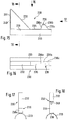
- the bicycle parker system shown in FIGS. 1 and 2, designated in its entirety by 10, has a multiplicity of alternately laterally offset double parkers 12, 12 ', which are held at a predetermined distance from one another by connecting pipe sections 14.
- the double parkers 12 and 12 ' are designed in a known manner so that they each have a U-shaped stand 16 bent from tubular material. These stands 16 are arranged in reverse, ie with the free ends of the two U-legs pointing downward towards the floor in laterally offset parallel vertical planes, the U-legs thus forming support legs 18 which are connected at their upper end by a web section 20 are connected.
- a side bracket 22 is provided on one of the two support legs 16 and extends parallel to the stand 16 at a lateral distance from it, so that the front wheel of a bicycle 24 is adjustable in the space formed between the stand and each side bracket, namely the side brackets 22 are each provided on different support legs 18 of the same stand, so that the bicycles 24 - for reasons of space economy - from opposite sides be set in the space between the side brackets and the stand.
- double parkers 12 and 12 ' are alternately arranged, which differ in that the support legs 18 of their stands 16 have different lengths.
- the side brackets 22 are arranged at such a height that the front wheels of a set vehicle rest on the floor.
- the side brackets 22 are arranged offset in height upwards, and in order to accommodate the front wheels of two-wheelers to be adjusted, a mounting bracket 26 is additionally arranged on both sides of the support legs 18, in which the front wheels are in a position raised from the ground can be set.
- the parts projecting laterally from the frame of the bicycle are offset in height from one another in successive parkers, so that the double parkers 12 and 12 'are moved closer together.
- the front wheels are secured by the mounting brackets 26 against tipping sideways in the lower region and by the side brackets in the upper region of the front wheel.
- brackets corresponding to the mounting brackets 26 are not provided, since in this area the connecting pipe sections 14 connecting the support legs 18 of adjacent Parker are fastened.
- the front wheel When a bicycle is placed in such a double parker 12, the front wheel is thus pushed over the connecting tube section 14 on the adjustment side and is then in the intended position Setting position between the two connecting pipe sections on the substrate. It is conceivable that the set front wheel can be moved laterally on the ground in the contact area and then tilted to one side or the other within the scope of the play given between the stand and the respective side bracket. If this tilting takes place in the direction of the stand, the upper part of the front wheel is leaned against the stand with the tube cover.
- FIG. 3 shows a support leg 18 of the stand 16 of a double parker 12, to which - in the drawing figure on the right side of the stand 18 - a connecting pipe section 14 is fastened in a manner known per se by means of a connecting sleeve 28 at a short distance above the floor, in the direction of arrow 3 in Fig. 2, ie from the inside.
- a connecting element in the form of a gusset plate 30 is arranged, which - as can also be seen in FIG.
- the gusset plate in which the gusset plate is shown separately - has the basic shape of an isosceles triangle, the hypotenuse of which is parallel to the floor at the level of the connecting pipe section 14 runs, while the cathets run from the triangular apex provided above the hypotenuse in the center on the support leg 18 from obliquely downwards and outwards to below the surface line of the connecting tube sections 14 lying at the top in the side view and thus each form an oblique boundary edge 32, which in each case in the space between the stand 16 and a side bracket 22 inserted front wheel inevitably slip in the direction of the lowest point of the boundary edge 32, so that the inserted front wheel and thus the bike overall a tendency to tilt in the direction of the stand 16 is forced.
- the cathets of the gusset plate 30 which form the boundary edges 32 are not led to the hypotenuse, but rather merge into a concave arc which extends into a vertically upwardly extending boundary edge 34 of an extension 36 integrally cut on the actual triangle and projecting above the respective connecting pipe section 14 above transforms.
- the boundary edge 34 thus forms a stop edge of the side stop for a set front wheel forming approach 36. That is, a tilting of the front wheel within the space between the stand 18 and the side bracket 22 is only possible to the extent that the hose cover of the set front wheel on the boundary edge 34th of the side stop approach 36 is present. This ensures that the front wheel cannot come into a tilting position that would endanger its rim.
- the gusset plate is fastened by means of fastening screws (not shown), the threaded shafts of which are at a short distance above the hypotenuse of the gusset plate
- the provided elongated holes 38 are screwed into a mating thread in the connecting pipe section 14 or the connecting sleeve 28 fixing the connecting pipe section 14 to the supporting leg 18.
- the fastening area of the connecting pipe sections 14 on the respective supporting leg 18 is additionally stiffened via the gusset plate 30, specifically in particular when an additional fastening screw is screwed into a threaded hole in the support leg 18 through the elongated hole 40, indicated by dash-dotted lines in FIGS. 3 and 4, in the apex region of the triangular gusset plate 30.
- the gusset plate 30 In addition to the task of inevitably guiding and holding the front wheel of a set bicycle, the gusset plate 30 also takes on the function of an additional reinforcement of the fastening area of connecting pipe sections 14 and support legs 18, so that such a series system 10 also withstand the stresses caused by inadvertently starting motor vehicles or withstand deliberate attempts at damage by individuals (vandalism) much better. Because of this reinforcement function, it can therefore make sense to provide gusset plates 30 not only on the double parkers 12, but also in the connection area of the higher double parkers 12 'with the subsequent connecting pipe sections 14, in which case the side stop approaches 36, which are then inoperative there, can be omitted. For reasons of simplification of the storage and assembly security, however, it can make sense to provide gusset plates of the type described, ie with side stop lugs 36, also in this fastening area.
- the formation of the through-openings for the fastening screws as elongated holes 38 and 40 enables the gusset plates 30 to be installed even if the threaded bores receiving the threaded shafts of the fastening screws are not drilled exactly in the prescribed position.
- the boundary edges 32 and 34 of the gusset plate 30 are deburred by grinding after the gusset plate has been punched out, a rounding or chamfering of the cut edges being recommended in order to avoid cut injuries to the rubber of the hose covers of the front wheel of adjusted bicycles.
- a - not shown in the drawing - design is possible such that in the areas of the boundary edges 32 and 34 with which the tube cover of a set front wheel can come into contact, a strip-shaped tab is cut on the sheet material of the gusset plate 30, which then bent or bent at right angles or even a little more than 90 ° after punching out.
- the gusset plate 30 is additionally stiffened.
- FIGS. 7 to 9 show the connection of a support leg 18 of a stand 16 to a connecting pipe section 14 by means of a somewhat modified gusset plate 30 '. Since the gusset plate 30 'shown separately in FIGS. 7 to 9 largely corresponds to the gusset plate 30 and the same parts are provided with the same reference numerals in the drawing figures, only the modifications of the gusset plate 30' compared to the gusset plate 30 are described below, while for the matching configurations can be referred to the preceding description of the gusset plate 30.
- Fig. 5 it can be seen that the hypotenuse of the triangular gusset plate runs somewhat lower than the lower lateral surface of the connecting pipe section 14 to be fastened, which is due to the fact that an approximately right-angled strip-shaped flange section 42 is attached to this hypotenuse below each cathete between which only the area of the support leg 18 is recessed.
- the folded flange sections 42 therefore lie on the underside of the connecting pipe sections 14 to be fastened in each case to the support leg 18, and the elongated holes 38 with which the gusset plate 30 'is fastened to the connecting pipe sections are accordingly also provided in these flange sections 42.
- the gusset plate 30 ′ is additionally stiffened again by the flange sections 42 and the position of the fastening screws on the underside of the connecting pipe sections 14 makes manipulation of the fastening screws difficult in such a way that the gusset plates are removed.
- FIGS. 10 to 14 An alternative to the gusset plates 30 and 30 'described above in connection with FIGS. 3 and 4 and 5 to 9 is shown in FIGS. 10 to 14.
- the connecting element 130 which takes the place of these gusset plates is, in the case shown, a plastic injection-molded part produced from two parts 130a, 130b, but in a similar configuration, production from metal casting is also conceivable.
- the connecting element 130 or the connecting element parts 130a, 130b is or are also basically triangular, but here an embodiment is shown which can also be used in a row system on the terminal bicycle parker, ie in which case only one side of a support leg 18 is used Connection pipe section 14 is attached. If a connecting pipe section 14 is attached to the support leg 18 on both sides on opposite sides, there is also a second connecting element 130 in a position symmetrically mirrored around the left vertical edge.
- the connecting element 130 has the shape of a right-angled triangle, the left vertical boundary of which is formed by a clamping section 131 which laterally encompasses the associated support leg 18, that is to say in horizontal section over an arc of up to 180 ° extends, wherein the inner radius of the clamping portion 131 is equal to the outer radius of the support leg 18.
- the clamping section 131 in turn then consists of clamping section parts 131a and 131b, which are each part of the connecting element parts 130a and 130b.
- a clamping section 133 is integrally formed on the lower horizontal boundary of the connecting element 130, which clampingly encompasses the associated connecting pipe section 14, to a large extent completely, i.e. the clamping section 133 extends over - almost - 360 °.
- Each clamping section part 133a or 133b thus covers an arc of - almost - 180 °.
- An integrally molded straight rib 132 which in turn is composed of two rib parts 132a and 132b, runs obliquely downward from the upper end of the clamping section 131 into the region of the end of the clamping section 131.
- the top of this rib forms the oblique boundary edge on which the front wheel of a bicycle to be adjusted slides, so that the bicycle assumes the position inclined to the stand 16.
- the space enclosed between the clamping sections 131, 133 and the oblique rib 132 is not open, but is closed by a thinner wall 135, which are formed by two superposed wall parts 135a, 135b half the wall thickness.
- the connecting element parts 130a, 130b are connected to the connecting element 130 by screwing the wall parts 135a, 135b with fastening screws (not shown).
- two circular reinforcing eyes 137a, 137b protruding from the outer sides of the walls 135a, 135b are provided for this purpose, through which holes 138 pass, through which the threaded shafts of the fastening screws are passed.
- connecting the parts 130a, 130b are also conceivable, in particular when producing the connecting elements from plastic.
- push-button-like latching elements can be provided in the adjoining surfaces of the parts 130a, 130b of the connecting element, which simply clip the parts 130a, 130b of the connecting element 130 from the front and back of the connecting area of a support leg 18 with an associated connecting pipe section 14 enable.
- FIGS. 10 and 14 each show an opening 139 provided partly in the wall 135 and partly in the clamping section 133, which serves to receive the head of a fastening screw projecting upwards from the connecting pipe section 14, with which the pipe section 14 is attached to the support leg 18 via a connecting sleeve.
- the head of the fastening screw projecting into the opening 139 simultaneously secures the connecting element 130 in the intended fastening position against displacements in the longitudinal direction of the respective connecting pipe section 14.
- FIGS. 15 to 18 an embodiment of a modified connecting element, designated in its entirety with 230, is shown, which is practically composed of two parts, namely an elongated base element 233, which is designed as an elongated base plate in cross-section corresponding to the outer diameter of the connecting pipe sections 14, which is in the connection area of a connecting pipe section 14 with a support leg 18 can be placed on the connecting pipe section, on which a component made of an elongated metal profile, in the illustrated case a flat iron, is placed by folding or bending into a series of metal profile sections and is fastened, this fastening either by welding individual sections resting on the upper side of the base element or by other conventional connecting means, such as riveting, screwing or the like. can be done.
- an elongated base element 233 which is designed as an elongated base plate in cross-section corresponding to the outer diameter of the connecting pipe sections 14, which is in the connection area of a connecting pipe section 14 with a support leg 18 can be placed on the connecting pipe section, on which
- FIG. 15 it can be seen that the obliquely running and the front wheel of a two-wheeler to be inserted into a Parker is forced into the desired oblique boundary edge by the upper side of a section 232 of the metal profile, the one end of which - on the right in FIG an angled intermediate section 235 fastened to the base part 233 passes over, while from its other end, which is guided obliquely upwards to the support leg, a section 231, which runs parallel to the support leg down to the base element 233 and is fastened there again, is attached.
- the profile material section forming the side stop projection 236 is integrally attached to the intermediate section 235 and is composed of sections, of which the section 236a is bent upwards from the intermediate section 235, the subsequent subsection 236b roughly folded back into the horizontal position and the next subsection 236c then folded back obliquely down to the base element 233 and fastened to the base element.
- a fastening hole 240 which is then again expediently designed as an elongated hole, can additionally be provided in the profile material section 231.
- the metal profile used for the formation of the metal profile sections is a flat iron. It can be seen that instead of such a flat iron, other metal profiles, for example round steel or tubular profiles, can also be used.
- Such connecting elements are also conceivable in such a way that instead of gusset plates, correspondingly curved metal profiles on the support legs 18 on the one hand and the connecting pipe sections 14 on the other hand are fastened directly - ie without a support element corresponding to the base element 233 - only care being taken in each case, that the connecting elements must have the inclined boundary edge influencing the tilting of a front wheel set in the Parker in the direction of the stand 16, and that in a suitable manner Distance from the support leg comes a side stop approach with a boundary edge upwards, which prevents the front wheel from tipping too much.
Landscapes
- Engineering & Computer Science (AREA)
- Mechanical Engineering (AREA)
- Fencing (AREA)
- Refuge Islands, Traffic Blockers, Or Guard Fence (AREA)
- Motorcycle And Bicycle Frame (AREA)
Abstract
Description
Die Erfindung betrifft eine Fahrradparker-Reihenanlage aus einer Anzahl von Einzel- oder Doppel-Parkern, die jeweils einen in einer senkrechten Ebene angeordneten, aus Rohrmaterial gebogenen Ständer aufweisen, der sich mit dem freien Ende wenigstens eines, vorzugsweise zweier Stützschenkel auf dem Boden abstützt oder in den Boden eingelassen ist, wobei einander zugeordnete Stützschenkel der Ständer benachbarter Parker durch horizontale Verbindungs-Rohrabschnitte verbunden sind, deren freie Enden jeweils am Stützschenkel eines der Parker befestigt sind.The invention relates to a series of bicycle parking systems consisting of a number of single or double parkers, each of which has a stand which is arranged in a vertical plane and is made of tubular material and which is supported on the floor by the free end of at least one, preferably two, support legs is embedded in the ground, with mutually associated support legs of the stands of adjacent Parkers being connected by horizontal connecting pipe sections, the free ends of which are each fastened to the support legs of one of the Parkers.
Fahrräder kommen in neuerer Zeit - auch aufgrund des gestiegenen Umweltbewußtseins - in zunehmendem Maße wieder in Gebrauch als Einzelbeförderungs und Transportmittel für Einkäufe in Städten. Dementsprechend müssen im innerstädtischen Bereich durch die Gemeinden oder auch die interessierte Geschäftswelt Abstellmöglichkeiten für Fahrräder geschaffen werden. Auch an Bahnhöfen (Park-and-Ride-Stationen), Schwimmbädern, Freizeitzentren, Sportanlagen, Schulen, Universitäten etc. werden in zunehmendem Maße Abstellmöglichkeiten für Fahrräder benötigt, in denen die Fahrräder gegen Beschädigung geschützt und gegen Diebstahl sicher anschließbar eingestellt werden können. Insbesondere dort, wo mit Abstellbedarf für eine größere Anzahl von Fahrrädern zu rechnen ist, werden Fahrradparker-Reihenanlagen der eingangs erwähnten Art vorgesehen, wobei die Fahrradparker zur Vermeidung von Diebstahl oder auch von Beschädigungen durch den in jüngerer Zeit in zunehmendem Maße beobachteten Vandalismus o.dgl. entweder durch Einbetonieren der senkrechten Stützschenkel oder eine nur schwer lösbare Verdüblung von Fußplatten am unteren Ende der Stützschenkel befestigt werden. Grundsätzlich haben sich solche Reihenanlagen bewährt, wobei aber - wie bereits erwähnt - das Problem von zunehmendem Vandalismus, d.h. mutwilliger Beschädigung, gegeben ist. Dem muß durch eine besonders stabile Ausgestaltung der Parker-Reihenanlage entgegengewirkt werden. Ein weiteres Problem betrifft die Tatsache, daß solche Reihenanlagen so ausgestaltet sein müssen, daß die in sie eingestellten Fahrräder gegen Umkippen sicher gehalten werden müssen, ohne daß es hierbei durch Einquetschung der Felgen des Vorderrades zu Beschädigungen kommt. Bewährt haben sich in diesem Zusammenhang Einzel- bzw. Doppelfahrradparker der eingangs erwähnten Art, bei denen an dem aus Rohrmaterial gebogenen metallischen Ständer mit Abstand vom Boden ein Seitenbügel an den Stützschenkel angebracht ist, der zwischen sich und dem Standbügel einen Einschubraum für das Vorderrad eines zu halternden Fahrrades schafft. Bei der Ausbildung als Doppelparker sind die Seitenbügel auf den gegenüberliegenden Seiten des Ständers so angeordnet, daß die Fahrräder von entgegengesetzten Seiten aus in den Zwischenraum zwischen dem Ständer und den Seitenbügeln eingeschoben werden können. Um zu verhindern, daß das eingeschobene Vorderrad im Zwischenraum zwischen dem Seitenbügel und dem Ständer verkippen kann, ist außerdem in der Nähe des Bodens noch ein seitlich geschlossener an den beiden Stützschenkeln befestigter Standbügel vorgesehen. Wenn diese bewährte Fahrradparker zu Reihenanlagen zusammengeschlossen werden sollen, werden die Stützschenkel benachbarter Standbügel durch bodennahe Verbindungs-Rohrabschnitte verbunden, wobei zur Erhöhung der Aufnahmekapazität der Reihenanlage und zur Verringerung des Verbrauchs an Bodenfläche benachbarte Fahrradparker in der Regel so ausgestaltet sind, daß in Aufeinanderfolge einstellbare Fahrräder abwechselnd mit angehobenem Vorderrad und auf dem Boden aufgesetzten Vorderrad in die Parker eingestellt werden. Für die in solchen Reihenanlagen verwendeten Parker, bei denen die Vorderräder angehoben werden müssen, werden die geschilderten Fahrradparker praktisch unverändert übernommen, wobei lediglich die unteren Enden der Stützschenkel so verlängert werden, daß die seitlichen Vorderrad-Aufnahmebügel entsprechend vom Boden abgehoben sind. Bei den jeweils dazwischenliegenden Parkern, bei denen das Vorderrad des eingestellten Fahrrades in Bodenhöhe bleiben soll, ist die Anbringung der Vorderrad-Aufnahmebügel nur bedingt möglich, weil in diesem Bereich die die Stützschenkel benachbarter Parker verbindenden Verbindungs-Rohrabschnitte angesetzt werden. Für die Vorderräder der in den tiefer stehenden Parkern zu halternden Fahrräder ist also keine seitliche Halterung durch einen Vorderrad-Aufnahmebügel gegeben und es kann in Einzelfällen vorkommen, daß ein eingestelltes Fahrrad seitlich wegkippt, wobei Beschädigungen der Felgen des Vorderrades insbesondere dann zu befürchten sind, wenn die Kippbewegung des Fahrrades vom eigenen Standbügel weg erfolgt, d.h. die Quetschung der Felge am Seitenbügel auftritt. Bei entgegengesetztem Kippen wirkt der hoch aufragende Ständer wie ein Anlehnbügel, so daß dann Beschädigungen der Felge nicht oder nur dann, wenn der Kippwinkel zu stark wird, zu befürchten sind.In recent times, bicycles are increasingly being used again - also because of increased environmental awareness - as individual transport and means of transport for shopping in cities. Accordingly, parking spaces for bicycles must be created in the inner-city area by the communities or the interested business community. Also at train stations (park and ride stations), Swimming pools, leisure centers, sports facilities, schools, universities etc. are increasingly required to store bicycles, in which the bicycles can be protected against damage and securely locked against theft. In particular, where parking space for a large number of bicycles is to be expected, in-line bicycle parking facilities of the type mentioned at the outset are provided, with the bicycle parker or the like to avoid theft or damage due to the increasingly observed vandalism or the like . either by concreting in the vertical support leg or a hard-to-detachable dowel from footplates at the lower end of the support leg. In principle, such series systems have proven themselves, but - as already mentioned - there is the problem of increasing vandalism, ie willful damage. This must be counteracted by a particularly stable design of the Parker in-line system. Another problem relates to the fact that such in-line systems must be designed in such a way that the bicycles set in them must be held securely against tipping over without damage being caused by crushing the rims of the front wheel. In this context, single or double bicycle parkers of the type mentioned at the outset have proven themselves, in which a side bracket is attached to the support leg at a distance from the ground on the metallic stand which is bent from tubular material and which has an insertion space for the front wheel between itself and the support bracket holding bike creates. In the training as a double parker, the side brackets are arranged on the opposite sides of the stand so that the bicycles can be inserted from opposite sides into the space between the stand and the side brackets. In order to prevent the inserted front wheel from tilting in the space between the side bracket and the stand, there is also a laterally closed one on the two near the floor Support legs of attached stirrups provided. If these tried-and-tested bicycle parkers are to be combined into row systems, the support legs of adjacent stirrups are connected by connecting pipe sections close to the ground, in order to increase the absorption capacity of the series system and to reduce the consumption of floor space, adjacent bicycle parkers are generally designed in such a way that bicycles which can be adjusted in succession are designed alternately in the Parker with the front wheel raised and the front wheel on the ground. For the Parker used in such series systems, in which the front wheels have to be raised, the bicycle parkers described are practically unchanged, with only the lower ends of the support legs being extended so that the lateral front wheel mounting brackets are lifted off the ground accordingly. In the case of the parkers in between, in which the front wheel of the set bicycle is to remain at ground level, the attachment of the front wheel mounting bracket is only possible to a limited extent, because in this area the connecting pipe sections connecting the support legs of adjacent parkers are attached. For the front wheels of the bicycles to be held in the lower parkers there is therefore no lateral mounting by a front wheel mounting bracket and in individual cases it can happen that a set bicycle tilts sideways, with damage to the rims of the front wheel being particularly fearful if the bicycle tilts away from its own stand bracket, ie the rim is crushed on the side bracket. When tilted in the opposite direction, the tower stands up like a leaning bracket so that there is no risk of damage to the rim or only if the tilt angle becomes too strong.
Der Erfindung liegt die Aufgabe zugrunde, Fahrradparker-Reihenanlagen der eingangs erwähnten Art so auszugestalten, daß sichergestellt ist, daß die in sie eingestellten Fahrräder eine hohe Standsicherheit erhalten und trotzdem felgenschonend benutzt werden können. Darüber hinaus sollen sie durch eine entsprechend stabile Verbindung ihrer Teile in besonderem Maße widerstandsfähig gegen Vandalismus ausbildbildbar sein.The invention has for its object to design bicycle parker row systems of the type mentioned so that it is ensured that the bicycles set in them maintain a high level of stability and still be easy on the rim. In addition, they should be capable of being trained to be particularly resistant to vandalism by a correspondingly stable connection of their parts.
Ausgehend von einer Fahrradparker-Reihenanlage der eingangs erwähnten Art wird diese Aufgabe erfindungsgemäß dadurch gelöst, daß im Befestigungsbereich der Verbindungs-Rohrabschnitt mit den Stützschenkeln ein im Bereich des jeweiligen Stützschenkels über die Höhe der Rohrabschnitte nach oben vorstehendes Verbindungselement angeordnet ist, welches von seinem höchsten Punkt aus mit einer jeweils schräg verlaufenden Begrenzungskante zu den anschließenden Verbindungs-Rohrabschnitten herabgeführt ist. Das Verbindungselement, dessen schräg verlaufende Begrenzungskanten Führungen für die eingeschobenen Vorderräder der zu halternden Fahrräder in dem Sinne bilden, daß die Fahrräder in eine in Richtung zum Ständer gerichtete Neigung gebracht werden und so ein Wegkippen in entgegengesetzter Richtung, d.h. vom zugeordneten Ständer weg, mit Sicherheit vermieden wird, kann auch zur zusätzlichen Verstärkung der Befestigung der Verbindungs-Rohrabschnitte und der Stützschenkel dienen.Starting from a series of bicycle parking facilities of the type mentioned at the outset, this object is achieved according to the invention in that in the fastening region of the connecting pipe section with the supporting legs, a connecting element projecting upward in the region of the respective supporting leg above the height of the pipe sections is arranged, which from its highest point is led down from each with an inclined boundary edge to the subsequent connecting pipe sections. The connecting element, the inclined boundary edges of which form guides for the inserted front wheels of the bicycles to be held in the sense that the bicycles are brought into an inclination in the direction of the stand and thus tilting away in the opposite direction, i.e. away from the associated stand, with certainty avoided, can also serve to additionally reinforce the fastening of the connecting pipe sections and the support legs.
Das Verbindungselement wird zweckmäßig an den Verbindungs-Rohrabschnitten und in vorteilhafter Weiterbildung der Erfindung dann auch am Stützschenkel befestigt.The connecting element is expediently attached to the connecting pipe sections and, in an advantageous development of the invention, also to the supporting leg.
In einer bevorzugten Ausgestaltung der Erfindung sind die Verbindungselemente in ihren zu den Verbindungs-Rohrabschnitten herabgeführten Endbereiche mit jeweils einem über die Verbindungs-Rohrabschnitte nach oben vortretenden, einen das seitliche Wegrutschen des Vorderrades eines eingestellten Fahrrades verhindernden Seitenanschlag bildenden Ansatz versehen.In a preferred embodiment of the invention, the connecting elements are provided in their end regions which lead down to the connecting tube sections, each with an approach which projects upwards over the connecting tube sections and forms a side stop which prevents the front wheel of a set bicycle from slipping away sideways.
Die Verbindungselemente sind in bevorzugter Weiterbildung der Erfindung als Knotenbleche ausgebildet, welche die grundsätzliche Form eines gleichschenkligen Dreiecks haben, dessen Hypotenuse im wesentlichen in Höhe der unteren Begrenzung der Verbindungs-Rohrabschnitte verläuft, während die Katheten die schräg verlaufenden Begrenzungskanten bilden.In a preferred development of the invention, the connecting elements are designed as gusset plates, which have the basic shape of an isosceles triangle, the hypotenuse of which runs essentially at the lower limit of the connecting pipe sections, while the cathets form the obliquely running boundary edges.
Die Seitenanschlag-Ansätze sind dann jeweils im Bereich des Zusammentreffens der Katheten mit der Hypotenuse integral am Knotenblech angeschnitten.The side stop approaches are then integrally cut on the gusset plate in the area where the cathets meet the hypotenuse.
Das Knotenblech kann jeweils mittels Befestigungsschrauben am Stützschenkel und/oder den Verbindungs-Rohrabschnitten befestigt sein, wobei die Gewindeschäfte der Befestigungsschrauben durch Durchgangsöffnungen in den Knotenblechen hindurch in den jeweiligen Stützschenkel bzw. Verbindungs-Rohrabschnitt eingeschraubt sind.The gusset plate can in each case be fastened to the support leg and / or the connecting pipe sections by means of fastening screws, the threaded shafts of the fastening screws being screwed through through openings in the gusset plates into the respective supporting leg or connecting pipe section.
Dabei wird eine zusätzliche Versteifung des Knotenblechs und eine Sicherung gegen ungewolltes Herausschrauben der Befestigungsschrauben dann erhalten, wenn im unteren hypotenusenseitigen Bereich des Knotenblechs unterhalb jeder Kathete jeweils ein etwa rechtwinklig umgekanteter streifenförmiger Flanschabschnitt angesetzt ist, welcher an der Unterseite der Verbindungs-Rohrabschnitte anliegt. Die Befestigung des Knotenblechs an den Verbindungs-Rohrabschnitten erfolgt dann zweckmäßig dadurch, daß die Durchgangsöffnungen in den umgekanteten Flanschabschnitten vorgesehen werden, so daß die Befestigungsschrauben also von unten in die Verbindungs-Rohrabschnitte eingeschraubt werden und so gegen mutwilliges Herausdrehen durch Unbefugte weitgehend gesichert sind.An additional stiffening of the gusset plate and a safeguard against unintentional unscrewing of the fastening screws is then obtained when in the lower hypotenuse-side area of the gusset plate underneath each catheter an approximately right-angled strip-shaped flange section is attached, which bears against the underside of the connecting pipe sections. The gusset plate is then fastened to the connecting pipe sections appropriately by providing the through-openings in the folded flange sections, so that the fastening screws are screwed into the connecting pipe sections from below and are largely secured against willful unscrewing by unauthorized persons.
Die Durchgangsöffnungen im Knotenblech selbst können - zum Ausgleich von Herstellungs- oder Montageungenauigkeiten - als Langlöcher ausgebildet sein.The through openings in the gusset plate itself can be designed as elongated holes to compensate for manufacturing or assembly inaccuracies.
Wenn die Befestigung der Verbindungs-Rohrabschnitte mit dem zugeordneten Stützschenkel des Ständer durch am Stützschenkel befestigte, passend in die offenen Enden der Verbindungs-Rohrabschnitte eingreifende stopfenartige Verbindungsmuffen (DE-GM 90 12 662.9) erfolgt, werden die Schäfte der Befestigungsschrauben zweckmäßig durch Öffnungen im Knotenblech und dem jeweiligen Verbindungs-Rohrabschnitt hindurch in eine Gewindebohrung in der jeweiligen Verbindungsmuffe eingeschraubt. Es bietet sich dann an, zur Befestigung des Knotenblechs und des Verbindungs-Rohrabschnitts jeweils die gleiche Verbindungsschraube zu verwenden.If the connection pipe sections are attached to the associated support leg of the stand by plug-like connection sleeves (DE-GM 90 12 662.9) which are attached to the support leg and fit into the open ends of the connection pipe sections, the shafts of the fastening screws are expediently made through openings in the gusset plate and screwed through the respective connecting pipe section into a threaded bore in the respective connecting sleeve. It then makes sense to use the same connecting screw to fasten the gusset plate and the connecting pipe section.
Die von den Katheten des dreieckigen Knotenblechs gebildeten schräg verlaufenden Begrenzungskanten und/oder die dem Stützschenkel zugewandten Begrenzungskanten der Seitenanschlag-Ansätze sind - zur Vermeidung von Beschädigungen des Gummis der Decken des Vorderrades des einzustellenden Rades - zweckmäßig entgratet und/oder angefast bzw. abgerundet.The oblique bounding edges formed by the cathets of the triangular gusset plate and / or the bounding edges of the side stop approaches facing the support leg are expediently deburred and / or chamfered or rounded in order to avoid damage to the rubber of the covers of the front wheel of the wheel to be adjusted.
Alternativ können von den die Katheten des dreieckigen Knotenblechs bildenden schräg verlaufenden Begrenzungskanten einstückig angeschnittene Streifen des Blechmaterials umgekantet sein. Beim Abgleiten des Vorderrades in die bestimmungsgemäße, zum Ständer geneigte Lage können dann keine scharfen Kanten auf das Gummimaterial des Vorderrades des eingestellten Fahrrades einwirken.Alternatively, strips of the sheet metal material cut in one piece can be folded over from the obliquely running boundary edges forming the cathets of the triangular gusset plate. When the front wheel slides into the intended position inclined to the stand, no sharp edges can then act on the rubber material of the front wheel of the set bicycle.
Auch von der dem Stützschenkel zugewandten Begrenzungskante des Seitenanschlag-Ansatzes kann in gleicher Weise ein einstückig angeschnittener Streifen des Blechmaterials des Knotenblechs umgekantet sein.An integrally cut strip of the sheet material of the gusset plate can also be folded over in the same way from the boundary edge of the side stop attachment facing the support leg.
Wenn bei Verwendung der oben geschilderten bekannten Doppelparker (DE-GM 87 15 865.5) oberhalb der Verbindungs-Rohrabschnitte an einem der Stützschenkel des Ständers jeweils ein das Vorderrad eines einzustellenden Fahrrades auf der dem Ständer gegenüberliegenden Seite umgreifender Seitenbügel vorgesehen ist, ist der lichte Abstand der dem Stützschenkel zugewandten Begrenzungskante des Seitenanschlag-Ansatzes vom zugeordneten Stützschenkel vorzugsweise wenigstens gleich dem lichten Abstand zwischen dem Stützschenkel und dem jeweiligen Seitenbügel gewählt. Damit ist sichergestellt, daß die Neigung des Vorderrades und somit des eingestellten Fahrrades in Richtung zum Ständer nicht so groß werden kann, daß die Felge des Vorderrades auf der ständerabgewandten Seite in Klemmeingriff mit dem Seitenbügel kommt.If when using the known double parker described above (DE-GM 87 15 865.5) above the connecting pipe sections on one of the support legs of the stand, the front wheel of a bicycle to be adjusted If the side bracket embracing the side opposite the stand is provided, the clear distance of the boundary edge of the side stop attachment facing the support leg from the associated support leg is preferably selected to be at least equal to the clear distance between the support leg and the respective side bracket. This ensures that the inclination of the front wheel and thus the set bicycle in the direction of the stand can not be so great that the rim of the front wheel on the side facing away from the stand comes into clamping engagement with the side bracket.
Anstelle der vorstehend beschriebenen, als Knotenblech aus Metall ausgebildeten Verbindungselemente können die Verbindungselemente auch als Kunststoff-Spritzgußteile oder als Metall-Gußteile ausgebildet sein.Instead of the connecting elements described above, designed as a gusset plate made of metal, the connecting elements can also be designed as plastic injection molded parts or as metal castings.
Dabei empfiehlt es sich dann, die Verbindungselemente derart zweiteilig auszubilden, daß sie den Verbindungsbereich des jeweiligen Stützschenkels mit dem Endbereich des anschließenden Verbindungs-Rohrabschnitts jeweils an der Vorder- bzw. Rückseite zumindest teilweise übergreifen, und daß der vorder- und rückseitige Teil des Verbindungselements dann in der bestimmungsgemäßen Befestigungsstellung miteinander verbunden werden.It is then advisable to form the connecting elements in two parts in such a way that they at least partially overlap the connecting area of the respective support leg with the end area of the adjoining connecting pipe section at the front and rear, respectively, and that the front and rear part of the connecting element then be connected to each other in the intended fastening position.
Die miteinander verbundenen Teile des Verbindungselements können dann so ausgestaltet sein, daß sie einen senkrechten, den Stützschenkel über höchstens 180° seitlich umgreifenden und einen waagerechten den zugeordneten Verbindungs-Rohrabschnitt über mehr als 180° von der Oberseite aus umgreifenden Klemmabschnitt aufweisen, wobei die die schräge Begrenzungskante bildenden Abschnitte sowie die den gegebenenfalls vorgesehenen Seitenanschlag-Ansatz bildenden Abschnitt der Verbindungselement-Teile jeweils integral an den Klemmabschnitten angesetzt sind.The interconnected parts of the connecting element can then be designed such that they have a vertical clamping section which laterally encompasses the support leg over a maximum of 180 ° and a horizontal clamping section encompassing the associated connecting pipe section over more than 180 ° from the top, the oblique section Sections forming the boundary edge and the section of the connecting element parts forming the optionally provided side stop projection are each integrally attached to the clamping sections.
Die Verbindung der Teile des Verbindungselements in der bestimmungsgemäßen Befestigungsstellung kann durch Verschrauben oder auch durch Verrasten von formschlüssig miteinander in Eingriff bringbaren komplementären Vorsprüngen und Ausnehmungen in den Verbindungselement-Teilen erfolgen.The connection of the parts of the connecting element in the intended fastening position can be carried out by screwing or also by latching complementary projections and recesses in the connecting element parts that can be positively engaged with one another.
Ein weiter abgewandeltes Ausführungsbeispiel der Erfindung kann so ausgebildet sein, daß das Verbindungselement ein jeweils im Befestigungsbereich eines Verbindungs-Rohrabschnitts mit dem zugeordneten Stützschenkel befestigbares langgestrecktes Basiselement aufweist, auf dessen dem Verbindungs-Rohrabschnitt abgewandter Oberseite ein Abschnitt eines langgestreckten metallischen Profilmaterials befestigt - beispielsweise aufgeschweißt - ist, welcher von seinem vom Stützschenkel entfernten Befestigungsbereich auf dem Basiselement aus schräg nach oben zum Stützschenkel verläuft und so mit seiner dem Basiselement abgewandten Seite die schräg verlaufende Begrenzungskante bildet.A further modified embodiment of the invention can be designed in such a way that the connecting element has an elongated base element which can be fastened in the fastening region of a connecting pipe section with the associated support leg, on the upper side of which, facing away from the connecting pipe section, a section of an elongated metallic profile material is fastened - for example welded on - is which extends obliquely upwards from the support area on the base element from the support leg to the support leg and thus forms the oblique boundary edge with its side facing away from the base element.
Außerdem kann auch hier wieder ein Seitenanschlag-Ansatz vorgesehen sein, welcher dadurch gebildet wird, daß auf der stützschenkelabgewandten Seite des Befestigungsbereichs des schräg verlaufenden Profilmaterial-Abschnitts auf dem Basiselement ein ebenfalls von einem Abschnitt eines metallischen Profilmaterials gebildeter, den Seitenanschlag bildender Ansatz angeordnet ist.In addition, a side stop shoulder can also be provided here, which is formed by arranging a shoulder which is also formed by a section of a metallic profile material and which forms the side stop on the base element side of the fastening region of the oblique profile material section on the base element.
Der den Seitenanschlag-Ansatz bildende Profilelement-Abschnitt kann dabei von einer Reihe von Teilabschnitten gebildet werden, von denen der erste Teilabschnitt vom Basiselement nach oben vortritt, während der sich anschließende Teilabschnitt in Richtung vom schräg verlaufenden Profilelement-Abschnitt weg und der nachfolgende Teilabschnitt zum Basiselement zurückgekantet oder gebogen und am Basiselement befestigt ist.The profile element section forming the side stop approach can be formed by a series of partial sections, of which the first partial section protrudes upward from the base element, while the subsequent partial section away from the oblique profile element section and the subsequent partial section to the base element folded back or bent and attached to the base element.
Am stützschenkelseitigen oberen Ende des die schräg verlaufende Begrenzungskante bildenden Profilmaterial-Abschnitt ist zweckmäßig ein parallel zum Stützschenkel senkrecht nach unten bis zum Basiselement geführter Abschnitt des Profilmaterials angesetzt, dessen unteres Ende auf dem Basiselement befestigt ist.At the support leg side upper end of the profile material section forming the oblique boundary edge, a section of the profile material, which lower end is fastened to the base element, is expediently guided parallel to the support leg and vertically down to the base element.
In diesem parallel zum Stützschenkel zum Basiselement geführten Profilmaterial-Abschnitt kann dann eine Befestigungsbohrung für den Schaft einer in eine Bohrung des Stützschenkels befestigbaren Befestigungsschraube o.dgl. vorgesehen sein.A fastening hole for the shaft of a fastening screw or the like which can be fastened in a hole in the support leg can then be fastened in this section of profile material guided parallel to the support leg to the base element. be provided.
Die Profilmaterial-Abschnitte des Verbindungselements sind in bevorzugter Ausgestaltung der Erfindung integrale Teile eines langgestreckten Metallprofils, welche also vor seiner Befestigung auf dem Basiselement so gekantet oder gebogen wird, daß die Profilmaterial-Abschnitte entstehen.In a preferred embodiment of the invention, the profile material sections of the connecting element are integral parts of an elongated metal profile, which is therefore bent or bent before it is attached to the base element in such a way that the profile material sections are created.
Das Basiselement wird zweckmäßig von einer in ihrem Querschnitt kreisabschnittsförmig gewölbten metallischen Fußplatte gebildet, wobei der Radius der dem Verbindungs-Rohrabschnitt zugewandten Seite der Fußplatte etwa gleich dem Radius der Außenfläche des zugeordneten Verbindungs-Rohrabschnitts gewählt ist. Die kreisabschnittsförmige Wölbung des Querschnitts der Fußplatte erstreckt sich dabei über einen Winkel von maximal 180°, um das Verbindungselement bei der Montage ohne Klemmung auf dem Verbindungs-Rohrabschnitt aufsetzen zu können.The base element is expediently formed by a metallic base plate which is curved in the form of a circular section, the radius of the side of the base plate facing the connecting pipe section being approximately equal to the radius of the outer surface of the associated connecting pipe section. The circular section-shaped curvature of the cross section of the base plate extends over an angle of a maximum of 180 ° in order to be able to place the connecting element on the connecting pipe section during the assembly without clamping.
Zur Befestigung des Basiselements auf dem Verbindungs-Rohrabschnitt kann im Bereich unterhalb des schräg verlaufenden Profilmaterial-Abschnitts etwa mittig eine Befestigungsbohrung für den Schaft einer Befestigungsschraube vorgesehen sein. Dabei ist die Lage der Befestigungsbohrung im Basiselement zweckmäßig so gewählt, daß sie mit einer im zugeordneten Verbindungs-Rohrabschnitt ohnehin vorgesehenen Befestigungsbohrung fluchtet. Basiselement und Verbindungs-Rohrabschnitt können dann gemeinsam mit einer Befestigungsschraube mit der die Verbindung des Verbindungs-Rohrabschnitts mit dem Stützschenkel herstellenden Muffe verschraubt werden.To fasten the base element on the connecting pipe section, a fastening bore for the shaft of a fastening screw can be provided approximately in the area below the oblique profile material section. The position of the mounting hole in the base element is expediently chosen so that it is provided in any case in the associated connecting pipe section Mounting hole is aligned. The base element and the connecting pipe section can then be screwed together with a fastening screw with the sleeve that connects the connecting pipe section to the support leg.
Die Befestigungsbohrung im Basiselement wird zum Ausgleich von eventuellen Ungenauigkeiten dann zweckmäßig als parallel zur Längsmittelachse des zugeordneten Verbindungs-Rohrabschnitts verlaufendes Langloch ausgebildet.To compensate for any inaccuracies, the fastening hole in the base element is then expediently designed as an elongated hole running parallel to the longitudinal central axis of the associated connecting pipe section.
Das für die Bildung der einzelnen Metallprofil-Abschnitte verwendete Metallprofil kann als Flach-, Rund- oder Rohrprofil ausgebildet sein.The metal profile used to form the individual metal profile sections can be designed as a flat, round or tubular profile.
Die Erfindung ist in der folgenden Beschreibung in Verbindung mit der Zeichnung näher erläutert, und zwar zeigt:
- Fig. 1
- eine schematische Ansicht eines Ausschnitts einer Fahrradparker-Reihenanlage der hier in Frage stehenden Art;
- Fig. 2
- eine Ansicht der Anlage, gesehen in Richtung des Pfeils 2 in Fig. 1;
- Fig. 3
- eine in vergrößertem Maßstab gezeigte Teilansicht des Verbindungsbereichs eines Stützschenkels mit einem Verbindungs-Rohrabschnitt durch ein in der erfindungsgemäßen Weise ausgebildetes Knotenblech;
- Fig. 4
- eine Ansicht des in Fig. 3 vewendeten Knotenblechs;
- Fig. 5
- eine in der Blickrichtung der Fig. 3 entsprechende Ansicht des Verbindungsbereichs eines Stützschenkels mit einem Verbindungs-Rohrabschnitt unter Verwendung eines gegenüber dem in Fig. 4 gezeigten Knotenblech abgewandelten Knotenblechs;
- Fig. 6
- eine Ansicht, gesehen in
Richtung des Pfeils 6 in Fig. 5; - Fig. 7
- das abgewandelte Knotenblech in Blickrichtung auf eine seiner Flachseiten;
- Fig. 8
- eine Ansicht des Knotenblechs, gesehen in Richtung des Pfeils 8 in Fig. 7;
- Fig. 9
- eine Ansicht des Knotenblechs, gesehen in
Richtung des Pfeils 9 in Fig. 7; - Fig. 10
- eine Seitenansicht eines als Kunststoff-Spritzgußteil ausgebildeten Ausführungsbeispiels eines Verbindungselements zur Verbindung eines Stützschenkels mit einem Verbindungs-Rohrabschnitt;
- Fig. 11
- eine Ansicht des Verbindungselements gesehen in Richtung des Pfeils 11 in Fig. 10;
- Fig. 12
- eine Ansicht des Verbindungselements gesehen in Richtung des Pfeils 12 in Fig. 10;
- Fig. 13
- eine Ansicht gesehen in
Richtung des Pfeils 13 in Fig. 10; - Fig. 14
- eine Schnittansicht in der durch die Pfeile 14-14 in Fig. 10 angegebene Schnittebene;
- Fig. 15
- eine Seitenansicht eines weiteren Ausführungsbeispiels eines Verbindungselements;
- Fig. 16
- eine Ansicht des Verbindungselements, gesehen in
Richtung des Pfeils 16 in Fig. 15; - Fig. 17
- eine Ansicht des Verbindungselements, gesehen in
Richtung des Pfeils 17 in Fig. 15; und - Fig. 18
- eine Schnittansicht in der durch die Pfeile 18-18 in Fig. 15 veranschaulichten Schnittebene.
- Fig. 1
- is a schematic view of a section of a bicycle parker row system of the type in question here;
- Fig. 2
- a view of the system, seen in the direction of
arrow 2 in Fig. 1; - Fig. 3
- a partial view, shown on an enlarged scale, of the connection region of a support leg with a connection pipe section through a gusset plate designed in the manner according to the invention;
- Fig. 4
- a view of the gusset plate used in Fig. 3;
- Fig. 5
- a view corresponding to the direction of FIG. 3 of the connection area a support leg with a connecting pipe section using a gusset plate which is modified compared to the gusset plate shown in FIG. 4;
- Fig. 6
- a view seen in the direction of
arrow 6 in Fig. 5; - Fig. 7
- the modified gusset plate facing one of its flat sides;
- Fig. 8
- a view of the gusset, seen in the direction of arrow 8 in Fig. 7;
- Fig. 9
- a view of the gusset, seen in the direction of
arrow 9 in Fig. 7; - Fig. 10
- a side view of a plastic injection molded embodiment of a connecting element for connecting a support leg to a connecting pipe section;
- Fig. 11
- a view of the connecting element seen in the direction of
arrow 11 in Fig. 10; - Fig. 12
- a view of the connecting element seen in the direction of
arrow 12 in Fig. 10; - Fig. 13
- a view seen in the direction of
arrow 13 in Fig. 10; - Fig. 14
- a sectional view in the sectional plane indicated by the arrows 14-14 in Fig. 10;
- Fig. 15
- a side view of another embodiment of a connecting element;
- Fig. 16
- a view of the connecting element, seen in the direction of
arrow 16 in Fig. 15; - Fig. 17
- a view of the connecting element, seen in the direction of
arrow 17 in Fig. 15; and - Fig. 18
- a sectional view in the sectional plane illustrated by the arrows 18-18 in Fig. 15.
Die in den Figuren 1 und 2 gezeigte, in ihrer Gesamtheit mit 10 bezeichnete Fahrradparker-Reihenanlage weist eine Vielzahl von abwechselnd seitlich versetzt angeordneten Doppelparkern 12, 12' auf, die durch Verbindungs-Rohrabschnitte 14 in vorgegebenem Abstand zueinander gehalten sind. Die Doppelparker 12 und 12' sind in bekannter Weise so ausgebildet, daß sie jeweils einen aus Rohrmaterial gebogenen U-förmigen Ständer 16 aufweisen. Diese Ständer 16 sind in umgekehrter, d.h. mit den freien Enden der beiden U-Schenkel nach unten zum Boden weisender Position in seitlich zueinander versetzten parallelen senkrechten Ebenen angeordnet, wobei die U-Schenkel also Stützschenkel 18 bilden, die an ihrem oberen Ende durch einen Stegabschnitt 20 verbunden sind. Auf den gegenüberliegenden Seiten der Ständer 16 ist jeweils ein an einem der beiden Stützschenkel 16 angebrachter Seitenbügel 22 vorgesehen, welche sich in seitlichem Abstand vom Ständer 16 parallel zu diesem erstrecken, so daß in den zwischen dem Ständer und jedem Seitenbügel gebildeten Zwischenraum das Vorderrad eines Fahrrades 24 einstellbar ist, und zwar sind die Seitenbügel 22 jeweils an verschiedenen Stützschenkeln 18 des gleichen Ständers vorgesehen, so daß die Fahrräder 24 - aus Gründen der Raumökonomie - von entgegengesetzten Seiten aus in den Zwischenraum zwischen den Seitenbügeln und dem Ständer eingestellt werden.The bicycle parker system shown in FIGS. 1 and 2, designated in its entirety by 10, has a multiplicity of alternately laterally offset
In der Reihenanlage 10 sind abwechselnd Doppelparker 12 und 12' angeordnet, die sich dadurch unterscheiden, daß die Stützschenkel 18 ihrer Ständer 16 unterschiedliche Länge haben. Bei den Doppelparkern 12 mit niedrigerem Ständer 16 sind die Seitenbügel 22 in solcher Höhe angeordnet, daß die Vorderräder eines eingestellten Fahrzeugs auf dem Boden aufruhen. Bei den Doppelparkern 12' mit höherem Ständer 16 sind die Seitenbügel 22 dagegen nach oben höhenversetzt angeordnet, und zur Aufnahme der Vorderräder von einzustellenden Zweirädern ist zusätzlich beidseitig an den Stützschenkeln 18 jeweils ein Aufnahmebügel 26 angeordnet, in welchen die Vorderräder in einer vom Boden abgehobenen Lage eingestellt werden. Dadurch sind die beidseits vom Rahmen des Fahrrades seitlich vorstehenden Teile, insbesondere der Fahrradlenker, in aufeinanderfolgenden Parkern zueinander höhenversetzt, so daß die Doppelparker 12 und 12' näher zusammengerückt werden. Bei den in die Doppelparker 12' eingestellten Fahrrädern werden die Vorderräder durch die Aufnahmebügel 26 gegen seitliches Wegkippen im unteren Bereich und durch die Seitenbügel im oberen Bereich des Vorderrades gesichert. Bei den Doppelparkern 12 mit niedrigerer Höhe der Ständer 16 sind dagegen den Aufnahmebügeln 26 entsprechende Bügel nicht vorgesehen, da in diesem Bereich die die Stützschenkel 18 seitlich benachbarter Parker verbindenden Verbindungs-Rohrabschnitte 14 befestigt sind. Beim Einstellen eines Fahrrades in einen solchen Doppelparker 12 wird das Vorderrad also über den einstellseitigen Verbindungs-Rohrabschnitt 14 hinweggeschoben und steht dann in der bestimmungsgemäßen Einstellage zwischen den beiden Verbindungs-Rohrabschnitten auf dem Untergrund. Dadurch ist es denkbar, daß das eingestellte Vorderrad im Aufstandsbereich auf dem Boden seitlich verschoben werden kann und dann im Rahmen des zwischen dem Ständer und dem jeweiligen Seitenbügel gegebenen Spiels nach der einen oder anderen Seite wegkippen kann. Sofern dieses Kippen in Richtung zum Ständer erfolgt, wird das Vorderrad in seinem oberen Bereich mit der Schlauchdecke am Ständer angelehnt. Kippt das Fahrrad jedoch in entgegengesetzter Richtung, kann seine Felge an den Seitenbügeln zur Anlage kommen und beschädigt werden, insbesondere dann, wenn ein Benutzer eines seitlich anschließenden Einstellplatzes unachtsam vorgeht und das gekippte Fahrrad zur Verbesserung der Zugänglichkeit zu seinem Einstellplatz beiseite drückt. Es besteht somit ein Bedürfnis bei Reihenanlagen 10 dafür zu sorgen, daß die in die Doppelparker 12 eingestellten Fahrräder gegen unzulässiges seitliches Wegkippen, d.h. gegen zu starkes Kippen und gegen Verkippen in der falschen Richtung, nämlich vom Ständer 16 weg gesichert werden. Hierfür sind anstelle derbei den Doppelparkern 12' vorgesehenen Aufnahmebügel 26 im Befestigungsbereich der Verbindungs-Rohrabschnitte 14 mit den Stützschenkeln 18 in geeigneter Weise ausgebildete Verbindungselemente angeordnet, von denen mögliche Ausführungsformen nachstehend noch in Verbindung mit den Figuren 3 und 4, 5 bis 9, 10 bis 14 und 15 bis 18 beschrieben sind.In the
Figur 3 zeigt einen Stützschenkel 18 des Ständers 16 eines Doppelparkers 12, an welchem - in der Zeichnungsfigur auf der rechten Seite des Ständers 18 - in an sich bekannter Weise mittels einer Verbindungsmuffe 28 in geringem Abstand über dem Boden ein Verbindungs-Rohrabschnitt 14 befestigt ist, und zwar in Blickrichtung des Pfeils 3 in Fig. 2, d.h. von innen. Im Befestigungsbereich des Verbindungs-Rohrabschnitts 14, zu welchem in einer Reihenanlage 10 ein auf der gegenüberliegenden Seite in gleicher Weise am Stützschenkel 18 angebrachter - hier nicht dargestellter - Verbindungs-Rohrabschnitt 14 zu denken ist, ist ein Verbindungselement in Form eines Knotenblechs 30 angeordnet, das - wie auch aus Fig. 4 hervorgeht, in welcher das Knotenblech separat dargestellt ist - die grundsätzliche Form eines gleichschenkligen Dreiecks hat, dessen Hypotenuse bodenparallel in Höhe des Verbindungs-Rohrabschnitts 14 verläuft, während die Katheten von dem oberhalb der Hypotenuse mittig am Stützschenkel 18 vorgesehenen Dreieck-Scheitel aus schräg nach unten und außen bis unterhalb der in der Seitenansicht oben liegenden Mantellinie der Verbindungs-Rohrabschnitte 14 verlaufen und somit jeweils eine schräge Begrenzungskante 32 bilden, welche ein jeweils in den Zwischenraum zwischen dem Ständer 16 und einen Seitenbügel 22 eingeschobenes Vorderrad zwangsläufig in Richtung des tiefsten Punktes der Begrenzungskante 32 abrutschen lassen, so daß dem eingeschobenen Vorderrad und somit dem Fahrrad insgesamt eine Tendenz zum Kippen in Richtung des Ständers 16 aufgezwungen wird. Die die Begrenzungskanten 32 bildenden Katheten des Knotenblechs 30 sind nicht bis zur Hypotenuse geführt, sondern gehen in einen konkaven Bogen über, der in eine senkrecht nach oben verlaufende Begrenzungskante 34 eines am eigentlichen Dreiecks integral angeschnittenen, den jeweiligen Verbindungs-Rohrabschnitt 14 oben überragenden Ansatzes 36 übergeht. Die Begrenzungskante 34 bildet also eine Anschlagkante des einen Seitenanschlag für ein eingestelltes Vorderrad bildenden Ansatzes 36. D.h. ein Verkippen des Vorderrades innerhalb des Zwischenraumes zwischen dem Ständer 18 und dem Seitenbügel 22 ist nur so weit möglich, daß die Schlauchdecke des eingestellten Vorderrades an der Begrenzungskante 34 des Seitenanschlag-Ansatzes 36 anliegt. Dadurch ist sichergestellt, daß das Vorderrad nicht in eine seine Felge gefährdende Kipplage kommen kann.FIG. 3 shows a
Die Befestigung des Knotenblechs erfolgt durch - nicht gezeigte - Befestigungsschrauben, deren Gewindeschäfte durch in geringem Abstand oberhalb der Hypotenuse des Knotenblechs vorgesehene Langlöcher 38 hindurch in ein Gegengewinde im Verbindungs-Rohrabschnitt 14 bzw. der den Verbindungs-Rohrabschnitt 14 am Stützschenkel 18 befestigenden Verbindungsmuffe 28 eingeschraubt sind Hierdurch wird der Befestigungsbereich der Verbindungs-Rohrabschnitte 14 am jeweiligen Stützschenkel 18 über das Knotenblech 30 zusätzlich versteift, und zwar insbesondere dann, wenn zusätzliche eine Befestigungsschraube durch das in den Fig. 3 und 4 strichpunktiert angedeutete, im Scheitelbereich des dreieckigen Knotenblechs 30 vorgesehene Langloch 40 in eine Gewindebohrung im Stützschenkel 18 eingeschraubt wird. Neben der Aufgabe einer zwangsläufigen Führung und Halterung des Vorderrades eines eingestellten Fahrrades übernimmt das Knotenblech 30 also auch die Funktion einer zusätzlichen Verstärkung des Befestigungsbereichs von Verbindungs-Rohrabschnitten 14 und Stützschenkeln 18, so daß eine solche Reihenanlage 10 also auch den Beanspruchungen durch versehentlich anfahrende Kraftfahrzeuge oder bewußten Beschädigungsversuchen durch Einzelpersonen (Vandalismus) deutlich besser standhalten. Aufgrund dieser Verstärkungsfunktion kann es deshalb durchaus sinnvoll sein, Knotenbleche 30 nicht nur an den Doppelparkern 12, sondern auch im Verbindungsbereich der höheren Doppelparker 12' mit den anschließenden Verbindungs-Rohrabschnitten 14 vorzusehen, wobei die dann dort funktionslosen Seitenanschlag-Ansätze 36 entfallen können. Aus Gründen der Vereinfachung der Lagerhaltung und der Montagesicherheit kann es jedoch durchaus sinnvoll sein, auch in diesem Befestigungsbereich Knotenbleche der beschriebenen Art, d.h. mit Seitenanschlag-Ansätzen 36 vorzusehen.The gusset plate is fastened by means of fastening screws (not shown), the threaded shafts of which are at a short distance above the hypotenuse of the gusset plate The provided
Die Ausbildung der Durchgangsöffnungen für die Befestigungsschrauben als Langlöcher 38 bzw. 40 ermöglicht die Montage der Knotenbleche 30 auch dann, wenn die die Gewindeschäfte der Befestigungsschrauben aufnehmenden Gewindebohrungen nicht exakt in der vorgeschriebenen Lage gebohrt sind.The formation of the through-openings for the fastening screws as
Die Begrenzungskanten 32 und 34 des Knotenblechs 30 sind nach dem Ausstanzen des Knotenblechs durch Beschleifen entgratet, wobei sich eine Abrundung bzw. ein Anfasen der Schnittkanten empfehlen kann, um Schnittverletzungen des Gummis der Schlauchdecken des Vorderrades von eingestellten Fahrrädern zu vermeiden. Darüber hinaus ist auch eine - in der Zeichnung nicht dargestellte - Ausgestaltung derart möglich, daß in den Bereichen der Begrenzungskanten 32 und 34, mit denen die Schlauchdecke eines eingestellten Vorderrades in Berührung kommen kann, am Blechmaterial des Knotenblechs 30 ein streifenförmiger Lappen angeschnitten ist, der dann nach dem Ausstanzen rechtwinklig oder sogar um etwas mehr als 90° umgekantet bzw. umgebogen wird. Dadurch wird nicht nur die jeweilige Begrenzungskante 32 bzw. 34 entschärft, sondern das Knotenblech 30 zusätzlich versteift.The boundary edges 32 and 34 of the
In Figur 3 ist noch erkennbar, daß der lichte Abstand A zwischen dem Stützschenkel 18 und der Begrenzungsfläche 34 des Seitenanschlag-Ansatzes 36 größer als der lichte Abstand a bzw. der Zwischenraum zwischen dem Stützschenkel 18 und dem Seitenbügel 22 ist.In Figure 3 it can still be seen that the clear distance A between the
In den Fig. 5 und 6 ist die Verbindung eines Stützschenkels 18 eines Ständers 16 mit einem Verbindungs-Rohrabschnitt 14 mittels eines etwas abgewandelten Knotenblechs 30' gezeigt. Da das in den Fig. 7 bis 9 separat dargestellte Knotenblech 30' dem Knotenblech 30 weitgehend entspricht und in den Zeichnungsfiguren gleiche Teile mit gleichen Bezugszeichen versehen sind, werden nachstehend nur die gegenüber dem Knotenblech 30 getroffenen Abwandlungen des Knotenblechs 30' beschrieben, während für die übereinstimmenden Ausgestaltungen auf die vorausgehende Beschreibung des Knotenblechs 30 verwiesen werden kann.5 and 6 show the connection of a
In Fig. 5 ist erkennbar, daß die Hypotenuse des dreieckigen Knotenblechs etwas tiefer als die untere Mantelfläche des zu befestigenden Verbindungs-Rohrabschnitts 14 verläuft, was seine Ursache darin hat, daß an dieser Hypotenuse unterhalb jeder Kathete jeweils ein etwa rechtwinklig umgekanteter streifenförmiger Flanschabschnitt 42 angesetzt ist, zwischen denen lediglich der Bereich des Stützschenkels 18 ausgespart ist. Die umgekanteten Flanschabschnitte 42 liegen also an der Unterseite der jeweils am Stützschenkel 18 zu befestigenden Verbindungs-Rohrabschnitte 14 an, und die Langlöcher 38, mit denen das Knotenblech 30' an den Verbindungs-Rohrabschnitten befestigt wird, sind demzufolge auch in diesen Flanschabschnitten 42 vorgesehen. Durch die Flanschabschnitte 42 wird das Knotenblech 30' wieder zusätzlich versteift und die Lage der Befestigungsschrauben an der Unterseite der Verbindungs-Rohrabschnitte 14 erschwert Manipulation an den Befestigungsschrauben derart, daß die Knotenbleche abgenommen werden.In Fig. 5 it can be seen that the hypotenuse of the triangular gusset plate runs somewhat lower than the lower lateral surface of the connecting
In den Figuren 10 bis 14 ist eine Alternative zu den vorstehend in Verbindung mit den Figuren 3 und 4 bzw. 5 bis 9 beschriebenen Knotenblechen 30 bzw. 30' dargestellt. Das an die Stelle dieser Knotenbleche tretende Verbindungselement 130 ist im dargestellten Fall ein aus zwei Teilen 130a, 130b hergestellter Kunststoff-Spritzgußteil, wobei aber in ähnlicher Ausgestaltung auch eine Herstellung aus Metall-Guß denkbar ist.An alternative to the
Das Verbindungselement 130 bzw. die Verbindungselement-Teile 130a, 130b ist bzw. sind ebenfalls grundsätzlich dreieckig, wobei hier jedoch eine Ausgestaltung gezeigt ist, die auch am endständigen Fahrradparker eine Reihenanlage einsetzbar ist, d.h. bei welchem also nur an einer Seite eines Stützschenkels 18 ein Verbindungs-Rohrabschnitt 14 angesetzt ist. Wenn am Stützschenkel 18 beidseitig auf gegenüberliegenden Seiten jeweils ein Verbindungs-Rohrabschnitt 14 angesetzt wird, ist zusätzlich ein zweites Verbindungselement 130 in einer um die linke senkrechte Kante symmetrisch gespiegelte Lage zu verwenden.The connecting
Fig. 10 zeigt eine Ansicht des Teils 130a des zweiteiligen Verbindungselements 130, wobei auf der nicht sichtbaren Rückseite des Teils 130a der nicht sichtbare spiegelbildliche Teil 130b aufgesetzt ist. Wie insbesondere in Fig. 10 hervorgeht, weist das Verbindungselement 130 die Form eines rechtwinkligen Dreiecks auf, dessen linke senkrechte Begrenzung von einem den zugeordneten Stützschenkel 18 seitlich hälftig umfassenden Klemmabschnitt 131 gebildet wird, der also im horizontalen Schnitt sich über einen Bogen bis zu 180° erstreckt, wobei der innere Radius des Klemmabschnitts 131 gleich dem äußeren Radius des Stützschenkels 18 ist. Der Klemmabschnitt 131 seinerseits setzt sich dann wieder aus Klemmabschnitt-Teilen 131a und 131b, welche jeweils Teil der Verbindungselement-Teile 130a bzw. 130b sind.10 shows a view of the
In ähnlicher Weise ist an der unteren waagerechten Begrenzung des Verbindungselements 130 ein Klemmabschnitt 133 angeformt, welcher der zugeordneten Verbindungs-Rohrabschnitt 14 klemmend umgreift, und zwar weitgehend vollständig, d.h. der Klemmabschnitt 133 erstreckt sich über - nahezu - 360°. Jeder Klemmabschnitt-Teil 133a bzw. 133b überdeckt also einen Bogen von - nahezu - 180°.In a similar manner, a
Vom oberen Ende des Klemmabschnitts 131 verläuft schräg nach unten in den Bereich des Endes des Klemmabschnitts 131 eine integral angeformte gerade Rippe 132, die sich wiederum aus zwei Rippenteilen 132a und 132b zusammensetzt. Die Oberseite dieser Rippe bildet die schräge Begrenzungskante, auf welcher das Vorderrad eines einzustellenden Fahrrades abgleitet, so daß das Fahrrad die zum Ständer 16 geneigte Lage annimmt. Der zwischen den Klemmabschnitten 131, 133 und der schrägen Rippe 132 eingeschlossene Raum ist nicht offen, sondern durch eine dünnere Wandung 135 geschlossen, die von zwei aufeinanderliegenden Wandungsteilen 135a, 135b halber Wandstärke gebildet werden.An integrally molded
Durch Verschrauben der Wandungsteile 135a, 135b mit (nicht gezeigten) Befestigungsschrauben werden die Verbindungselement-Teile 130a, 130b zum Verbindungselement 130 verbunden. Im dargestellten Fall sind hierfür zwei kreisförmig begrenzte von den Außenseiten der Wandungen 135a, 135b vortretende Verstärkungsaugen 137a, 137b vorgesehen, welche von Bohrungen 138 durchsetzt werden, durch welche die Gewindeschäfte der Befestigungsschrauben hindurch geführt werden.The connecting
Insbesondere bei Herstellung der Verbindungselemente aus Kunststoff sind aber auch andere Möglichkeiten der Verbindung der Teile 130a, 130b denkbar. So können beispielsweise in den aneinanderliegenden Flächen der Teile 130a, 130b des Verbindungselements ausgebildete druckknopfartige Rastelemente vorgesehen sein, welche ein einfaches Aufklipsen der Teile 130a, 130b des Verbindungselements 130 von der Vorder- und Rückseite des Verbindungsbereichs eines Stützschenkels 18 mit einem zugeordneten Verbindungs-Rohrabschnitt 14 ermöglichen.However, other possibilities of connecting the
Vom äußersten Ende des Klemmabschnitts 133 steht wiederum ein Seitenanschlag-Ansatz 136 vor, der sich wiederum aus aneinanderliegenden Teilen 136a, 136b zusammensetzt. In den Figuren 10 und 14 ist noch jeweils ein zum Teil in der Wandung 135 und zum Teil im Klemmabschnitt 133 vorgesehene Durchbruch 139 dargestellt, welcher dazu dient, den Kopf einer vom Verbindungsrohr-Abschnitt 14 nach oben vortretenden Befestigungsschraube aufzunehmen, mit welcher der Rohrabschnitt 14 über eine Verbindungsmuffe am Stützschenkel 18 befestigt ist. Der in den Durchbruch 139 ragende Kopf der Befestigungsschraube sichert das Verbindungselement 130 gleichzeitig in der bestimmungsgemäßen Befestigungsstellung gegen Verschiebungen in Längsrichtung des jeweiligen Verbindungsrohr-Abschnitts 14.From the outermost end of the
In den Figuren 15 bis 18 ist ein in seiner Gesamtheit mit 230 bezeichnetes Ausführungsbeispiel eines abgewandeltes Verbindungselements gezeigt, welches praktisch aus zwei Teilen zusammengesetzt ist, nämlich einem als im Querschnitt entsprechend dem Außendurchmesser der Verbindungs-Rohrabschnitte 14 gewölbte Fußplatte ausgebildeten langgestreckten Basiselement 233, welches also im Verbindungsbereich eines Verbindungs-Rohrabschnitts 14 mit einem Stützschenkel 18 auf dem Verbindungs-Rohrabschnitt aufsetzbar ist, auf welchem ein aus einem langgestreckten Metallprofil, und zwar im dargestellten Fall einem Flacheisen, durch Abkantung bzw. Umbiegen in eine Reihe von Metallprofil-Abschnitte unterteilter Bauteil aufgesetzt und befestigt ist, wobei diese Befestigung entweder durch Aufschweißen einzelner, auf der Oberseite des Basiselements aufliegender Abschnitte oder auch durch andere übliche Verbindungsmittel, wie Vernietung, Verschraubung o.dgl. erfolgen kann.In FIGS. 15 to 18, an embodiment of a modified connecting element, designated in its entirety with 230, is shown, which is practically composed of two parts, namely an
Insbesondere in Fig. 15 ist erkennbar, daß die schräg verlaufende und das Vorderrad eines in einen Parker einzuführenden Zweirades in die gewünschte Schräglage zwingende Begrenzungskante von der Oberseite eines Abschnitts 232 des Metallprofils gebildet wird, dessen eines - in Fig. 15 rechts gelegenes - Ende in einen auf dem Basisteil 233 befestigten abgewinkelten Zwischenabschnitt 235 übergeht, während von seinem anderen schräg nach oben zum Stützschenkel geführten Ende ein parallel zum Stützschenkel nach unten bis zum Basiselement 233 geführter und dort wieder befestigter Abschnitt 231 angesetzt ist.In particular, in FIG. 15 it can be seen that the obliquely running and the front wheel of a two-wheeler to be inserted into a Parker is forced into the desired oblique boundary edge by the upper side of a
Der den Seitenanschlag-Ansatz 236 bildende Profilmaterial-Abschnitt ist integral am Zwischenabschnitt 235 angesetzt und setzt sich aus Teilabschnitten zusammen, von denen der Teilabschnitt 236a vom Zwischenabschnitt 235 nach oben gekantet, der darauf folgende Teilabschnitt 236b etwa in die waagerechte Lage zurückgekantet und der nächst folgende Teilabschnitte 236c dann wieder schräg nach unten zum Basiselement 233 umgekantet und am Basiselement befestigt ist. Unterhalb des Profilmaterial-Abschnitts 232 ist mittig im Basiselement 233 eine - im dargestellten Fall als Langloch ausgebildete - Befestigungsbohrung 238 vorgesehen, durch welche hindurch der Schaft einer Befestigungsschraube hindurchschraubbar ist.The profile material section forming the
Für den Fall, daß zusätzlich eine Verbindung mit dem Stützschenkel 18 gefordert wird, kann zusätzlich im Profilmaterial-Abschnitt 231 eine dann zweckmäßig wiederum als Langloch ausgebildete Befestigungsbohrung 240 vorgesehen sein. Beim beschriebenen Verbindungselement 230 ist das für die Ausbildung der Metallprofil-Abschnitte verwendete Metallprofil ein Flacheisen. Es ist ersichtlich, daß anstelle eines solchen Flacheisens auch andere Metallprofile, beispielsweise Rundstähle oder Rohrprofile, verwendet werden können.In the event that a connection to the
Es ist ersichtlich, daß im Rahmen des Erfindungsgedankens Abwandlungen und Weiterbildungen der beschriebenen Ausführungsbeispiele verwirklichbar sind, welche sich insbesondere auf die Art und Weise der Befestigung der als Knotenbleche 30 bzw. 30' ausgebildeten Verbindungselemente, aber auch auf Ausgestaltung und Verbindungselemente selbst beziehen. Solche Verbindungselemente sind auch in der Weise vorstellbar, daß anstelle von Knotenblechen entsprechend gebogene Metallprofile an den Stützschenkeln 18 einerseits und den Verbindungs-Rohrabschnitten 14 andererseits direkt - d.h. ohne ein dem Basiselement 233 entsprechendes Trägerelement - befestigt werden, wobei jeweils lediglich darauf geachtet werden muß, daß die Verbindungselemente die das Kippen eines in den Parker eingestellten Vorderrades in Richtung zum Ständer 16 beeinflussende schräg verlaufende Begrenzungskante aufweisen müssen, und daß in geeignetem Abstand vom Stützschenkel jeweils ein Seitenanschlag-Ansatz mit einer Begrenzungskante nach oben vortritt, durch den ein zu starkes Kippen des Vorderrades verhindert wird.It can be seen that within the scope of the inventive concept, modifications and further developments of the exemplary embodiments described can be implemented, which relate in particular to the manner in which the connecting elements designed as
Claims (32)
dadurch gekennzeichnet,
daß im Befestigungsbereich der Verbindungs-Rohrabschnitte (14) mit den Stützschenkeln (18) ein im Bereich des jeweiligen Stützschenkels (18) über die Höhe der Rohrabschnitte (14) nach oben vorstehendes Verbindungselement (z.B. Knotenblech 30 bzw. 30'; 130; 230) angeordnet ist, welches von seinem höchsten Punkt aus mit einer jeweils schräg verlaufenden Begrenzungskante (32; 132; 232) zu den anschließenden Verbindungs-Rohrabschnitten (14) herabgeführt ist.In-line bicycle system, consisting of a number of single or double parkers, each of which has a stand which is arranged in a vertical plane and is made of tubular material and which is supported on the floor by the free end of at least one, preferably two, support legs or is embedded in the floor where the mutually associated support legs of the stands of adjacent Parkers are connected by horizontal connecting pipe sections, the free ends of which are each fastened to the support legs of one of the Parkers,
characterized by
that in the fastening area of the connecting pipe sections (14) with the support legs (18) a connecting element (for example gusset plate 30 or 30 ';130; 230) protruding upwards in the area of the respective support leg (18) above the height of the pipe sections (14) is arranged, which is led down from its highest point with a respective sloping boundary edge (32; 132; 232) to the connecting pipe sections (14).
Applications Claiming Priority (4)
| Application Number | Priority Date | Filing Date | Title |
|---|---|---|---|
| DE9409746U DE9409746U1 (en) | 1994-06-19 | 1994-06-19 | In-line bicycle parking facility |
| DE9409746U | 1994-06-19 | ||
| DE4430170 | 1994-08-25 | ||
| DE4430170A DE4430170C2 (en) | 1994-06-19 | 1994-08-25 | Parking bicycles in a row as |
Publications (2)
| Publication Number | Publication Date |
|---|---|
| EP0687619A1 true EP0687619A1 (en) | 1995-12-20 |
| EP0687619B1 EP0687619B1 (en) | 1998-03-25 |
Family
ID=25939513
Family Applications (1)
| Application Number | Title | Priority Date | Filing Date |
|---|---|---|---|
| EP95109074A Expired - Lifetime EP0687619B1 (en) | 1994-06-19 | 1995-06-13 | Supports for parking bicycles |
Country Status (2)
| Country | Link |
|---|---|
| EP (1) | EP0687619B1 (en) |
| AT (1) | ATE164358T1 (en) |
Cited By (2)
| Publication number | Priority date | Publication date | Assignee | Title |
|---|---|---|---|---|
| FR2756539A1 (en) * | 1996-12-02 | 1998-06-05 | Fort Maurice Francois | Bicycle anti-theft support |
| FR2758518A1 (en) * | 1997-01-20 | 1998-07-24 | Cousin Jean Pierre Joseph | Parking anti-theft device for cycles and mopeds |
Citations (5)
| Publication number | Priority date | Publication date | Assignee | Title |
|---|---|---|---|---|
| DE8715865U1 (en) | 1987-12-01 | 1988-01-21 | Groebe Feinstahlbau KG, 6525 Westhofen | Device for adjusting two-wheelers, such as bicycles, motorbikes, mopeds, etc. |
| DE8801595U1 (en) * | 1988-02-09 | 1988-03-31 | FRIESON Handelsgesellschaft für Metall- und Kunststoffprodukte mbH & Co KG, 5909 Burbach | Bicycle stand |
| DE9006455U1 (en) * | 1990-06-08 | 1990-08-16 | Koch, Arnim, 3500 Kassel | Combination bike stand |
| DE9012662U1 (en) | 1990-09-05 | 1990-11-08 | Orion Bausysteme GmbH, 6083 Biebesheim | Pipe connection |
| DE9404105U1 (en) * | 1994-03-11 | 1994-05-05 | ORION Bausysteme GmbH, 64584 Biebesheim | In-line bicycle parking facility as well as foundation and weighting bollards for this |
-
1995
- 1995-06-13 EP EP95109074A patent/EP0687619B1/en not_active Expired - Lifetime
- 1995-06-13 AT AT95109074T patent/ATE164358T1/en not_active IP Right Cessation
Patent Citations (5)
| Publication number | Priority date | Publication date | Assignee | Title |
|---|---|---|---|---|
| DE8715865U1 (en) | 1987-12-01 | 1988-01-21 | Groebe Feinstahlbau KG, 6525 Westhofen | Device for adjusting two-wheelers, such as bicycles, motorbikes, mopeds, etc. |
| DE8801595U1 (en) * | 1988-02-09 | 1988-03-31 | FRIESON Handelsgesellschaft für Metall- und Kunststoffprodukte mbH & Co KG, 5909 Burbach | Bicycle stand |
| DE9006455U1 (en) * | 1990-06-08 | 1990-08-16 | Koch, Arnim, 3500 Kassel | Combination bike stand |
| DE9012662U1 (en) | 1990-09-05 | 1990-11-08 | Orion Bausysteme GmbH, 6083 Biebesheim | Pipe connection |
| DE9404105U1 (en) * | 1994-03-11 | 1994-05-05 | ORION Bausysteme GmbH, 64584 Biebesheim | In-line bicycle parking facility as well as foundation and weighting bollards for this |
Cited By (2)
| Publication number | Priority date | Publication date | Assignee | Title |
|---|---|---|---|---|
| FR2756539A1 (en) * | 1996-12-02 | 1998-06-05 | Fort Maurice Francois | Bicycle anti-theft support |
| FR2758518A1 (en) * | 1997-01-20 | 1998-07-24 | Cousin Jean Pierre Joseph | Parking anti-theft device for cycles and mopeds |
Also Published As
| Publication number | Publication date |
|---|---|
| ATE164358T1 (en) | 1998-04-15 |
| EP0687619B1 (en) | 1998-03-25 |
Similar Documents
| Publication | Publication Date | Title |
|---|---|---|
| DE60129182T2 (en) | Modular fence | |
| DE602005004790T2 (en) | guardrail | |
| EP0945564A1 (en) | Shuttering table system | |
| EP0716803B1 (en) | Building element for making edges and borders in gardens and green spaces | |
| DE69932267T2 (en) | Fence with vertical elements | |
| EP0220395A1 (en) | Stand for bicycles | |
| DE4430170C2 (en) | Parking bicycles in a row as | |
| DE2908284C2 (en) | Formwork panel for concrete walls | |
| DE2850763A1 (en) | STAND FOR BICYCLES, BICYCLES WITH AUXILIARY MOTOR AND MOTORCYCLES | |
| EP0687619B1 (en) | Supports for parking bicycles | |
| DE19537078C2 (en) | Device for parking a bicycle standing on its wheels | |
| DE2949541C2 (en) | Beacon stand | |
| DE7818280U1 (en) | KIT FOR PROTECTIVE GRILLE FOR LIMITATION AND SECURITY PURPOSES, IN PARTICULAR FOR SCHOOL BUS STOPPING | |
| DE4403438A1 (en) | Baffle for motor vehicles | |
| DE9301629U1 (en) | Swimming pool roof made of several arched sections that can be moved on rails | |
| WO1998028181A1 (en) | Bicycle stand | |
| DE4314677A1 (en) | Parking system for two-wheelers | |
| DE29513037U1 (en) | Carrier system | |
| DE29712442U1 (en) | Mobile locking device | |
| DE19629893A1 (en) | Passable cover | |
| DE102022115390A1 (en) | Barrier system for the use of path or thoroughfare blocking | |
| DE4345134A1 (en) | Shelter, in particular passenger-vehicle shelter | |
| DE9308960U1 (en) | Two-wheel stand, especially for bicycles | |
| WO2005063554A1 (en) | Bicycle stand | |
| DE29606059U1 (en) | Stands for bicycles |
Legal Events
| Date | Code | Title | Description |
|---|---|---|---|
| PUAI | Public reference made under article 153(3) epc to a published international application that has entered the european phase |
Free format text: ORIGINAL CODE: 0009012 |
|
| AK | Designated contracting states |
Kind code of ref document: A1 Designated state(s): AT CH DK FR LI NL |
|
| 17P | Request for examination filed |
Effective date: 19960320 |
|
| GRAG | Despatch of communication of intention to grant |
Free format text: ORIGINAL CODE: EPIDOS AGRA |
|
| GRAG | Despatch of communication of intention to grant |
Free format text: ORIGINAL CODE: EPIDOS AGRA |
|
| GRAH | Despatch of communication of intention to grant a patent |
Free format text: ORIGINAL CODE: EPIDOS IGRA |
|
| 17Q | First examination report despatched |
Effective date: 19970904 |
|
| GRAH | Despatch of communication of intention to grant a patent |
Free format text: ORIGINAL CODE: EPIDOS IGRA |
|
| GRAA | (expected) grant |
Free format text: ORIGINAL CODE: 0009210 |
|
| AK | Designated contracting states |
Kind code of ref document: B1 Designated state(s): AT CH DK FR LI NL |
|
| PG25 | Lapsed in a contracting state [announced via postgrant information from national office to epo] |
Ref country code: NL Free format text: LAPSE BECAUSE OF FAILURE TO SUBMIT A TRANSLATION OF THE DESCRIPTION OR TO PAY THE FEE WITHIN THE PRESCRIBED TIME-LIMIT Effective date: 19980325 Ref country code: FR Free format text: LAPSE BECAUSE OF FAILURE TO SUBMIT A TRANSLATION OF THE DESCRIPTION OR TO PAY THE FEE WITHIN THE PRESCRIBED TIME-LIMIT Effective date: 19980325 |
|
| REF | Corresponds to: |
Ref document number: 164358 Country of ref document: AT Date of ref document: 19980415 Kind code of ref document: T |
|
| REG | Reference to a national code |
Ref country code: CH Ref legal event code: EP |
|
| PG25 | Lapsed in a contracting state [announced via postgrant information from national office to epo] |
Ref country code: AT Free format text: LAPSE BECAUSE OF NON-PAYMENT OF DUE FEES Effective date: 19980613 |
|
| PG25 | Lapsed in a contracting state [announced via postgrant information from national office to epo] |
Ref country code: DK Free format text: LAPSE BECAUSE OF FAILURE TO SUBMIT A TRANSLATION OF THE DESCRIPTION OR TO PAY THE FEE WITHIN THE PRESCRIBED TIME-LIMIT Effective date: 19980625 |
|
| EN | Fr: translation not filed | ||
| NLV1 | Nl: lapsed or annulled due to failure to fulfill the requirements of art. 29p and 29m of the patents act | ||
| PLBE | No opposition filed within time limit |
Free format text: ORIGINAL CODE: 0009261 |
|
| STAA | Information on the status of an ep patent application or granted ep patent |
Free format text: STATUS: NO OPPOSITION FILED WITHIN TIME LIMIT |
|
| 26N | No opposition filed | ||
| PG25 | Lapsed in a contracting state [announced via postgrant information from national office to epo] |
Ref country code: LI Free format text: LAPSE BECAUSE OF NON-PAYMENT OF DUE FEES Effective date: 19990630 Ref country code: CH Free format text: LAPSE BECAUSE OF NON-PAYMENT OF DUE FEES Effective date: 19990630 |
|
| REG | Reference to a national code |
Ref country code: CH Ref legal event code: PL |