EP0687490B1 - Magnetic ball lock for a pinball game - Google Patents
Magnetic ball lock for a pinball game Download PDFInfo
- Publication number
- EP0687490B1 EP0687490B1 EP95303807A EP95303807A EP0687490B1 EP 0687490 B1 EP0687490 B1 EP 0687490B1 EP 95303807 A EP95303807 A EP 95303807A EP 95303807 A EP95303807 A EP 95303807A EP 0687490 B1 EP0687490 B1 EP 0687490B1
- Authority
- EP
- European Patent Office
- Prior art keywords
- ball
- well
- playfield
- lock
- game
- Prior art date
- Legal status (The legal status is an assumption and is not a legal conclusion. Google has not performed a legal analysis and makes no representation as to the accuracy of the status listed.)
- Expired - Lifetime
Links
Images

Classifications
-
- A—HUMAN NECESSITIES
- A63—SPORTS; GAMES; AMUSEMENTS
- A63F—CARD, BOARD, OR ROULETTE GAMES; INDOOR GAMES USING SMALL MOVING PLAYING BODIES; VIDEO GAMES; GAMES NOT OTHERWISE PROVIDED FOR
- A63F7/00—Indoor games using small moving playing bodies, e.g. balls, discs or blocks
- A63F7/22—Accessories; Details
- A63F7/30—Details of the playing surface, e.g. obstacles; Goal posts; Targets; Scoring or pocketing devices; Playing-body-actuated sensors, e.g. switches; Tilt indicators; Means for detecting misuse or errors
- A63F7/305—Goal posts; Winning posts for rolling-balls
- A63F7/3065—Electric
- A63F7/3075—Electric imparting energy to the ball, e.g. bumper-kickers, reprojectors
-
- A—HUMAN NECESSITIES
- A63—SPORTS; GAMES; AMUSEMENTS
- A63F—CARD, BOARD, OR ROULETTE GAMES; INDOOR GAMES USING SMALL MOVING PLAYING BODIES; VIDEO GAMES; GAMES NOT OTHERWISE PROVIDED FOR
- A63F3/00—Board games; Raffle games
- A63F3/00643—Electric board games; Electric features of board games
- A63F2003/00662—Electric board games; Electric features of board games with an electric sensor for playing pieces
-
- A—HUMAN NECESSITIES
- A63—SPORTS; GAMES; AMUSEMENTS
- A63F—CARD, BOARD, OR ROULETTE GAMES; INDOOR GAMES USING SMALL MOVING PLAYING BODIES; VIDEO GAMES; GAMES NOT OTHERWISE PROVIDED FOR
- A63F7/00—Indoor games using small moving playing bodies, e.g. balls, discs or blocks
- A63F7/0088—Indoor games using small moving playing bodies, e.g. balls, discs or blocks using magnetic power
- A63F2007/0094—Indoor games using small moving playing bodies, e.g. balls, discs or blocks using magnetic power using electromagnetic action, e.g. for attracting a ball
-
- A—HUMAN NECESSITIES
- A63—SPORTS; GAMES; AMUSEMENTS
- A63F—CARD, BOARD, OR ROULETTE GAMES; INDOOR GAMES USING SMALL MOVING PLAYING BODIES; VIDEO GAMES; GAMES NOT OTHERWISE PROVIDED FOR
- A63F9/00—Games not otherwise provided for
- A63F9/24—Games using electronic circuits not otherwise provided for
- A63F2009/2401—Detail of input, input devices
- A63F2009/2436—Characteristics of the input
- A63F2009/2442—Sensors or detectors
- A63F2009/2444—Light detector
Definitions
- the invention relates generally to pinball games and, more particularly, to an improved ball lock for such games.
- a typical pinball game includes an inclined playfield supporting a rolling ball, player operated flippers and a plurality of play features.
- the game player controls flippers to propel the ball across the playfield. By properly manipulating the flippers, the player can direct the ball at desired play features to control play of the game and to score points.
- Ball locks typically consist of a mechanical device into which the ball rolls and where it remains until it is ejected by a solenoid operated kicker or similar device.
- Ball locks are commonly used to provide multiple ball play where a first ball is captured while play of the game continues with a second ball.
- the first ball may be ejected from the ball lock such that both the first and second balls are in play simultaneously thereby creating multiple ball play.
- a ball lock for a game having a playfield on which at least one ferromagnetic ball can roll comprising:
- a microprocessor controlled game and a ball lock for selectively receiving from and discharging a ball to the game playfield under processor control, comprising:
- the invention provides a ball lock for a game having a playfield on which at least one ferromagnetic ball can roll, the ball lock comprising:
- Figure 1 is a side section-view of the magnetic ball-lock of the invention.
- Figure 2 is a block diagram showing the electrical connections of the magnetic ball lock.
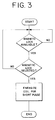
- Figure 3 is a flow diagram illustrating the operation of the magnetic ball lock by the game microprocessor.
- the magnetic ball-lock of the invention is shown located adjacent a path of travel 10 of a ferromagnetic pinball 12 on playfield 14.
- the path of travel can be defined by a chute, ramp, ball lane or the playfield itself.
- the magnetic ball lock 16 consists of a housing having a receiving well 18 for receiving the ball 12 and an electromagnet 20.
- the housing is disposed such that the well is at a shallow angle relative to the playfield as shown in Figure 1. As a result, a ball that enters the well will remain there until it is forcibly ejected.
- An optical sensor including a light emitter 22 and light detector 24 is operatively disposed near the bottom of well 18 such that it can detect the presence or absence of a ball therein. While an optical sensor is illustrated, it will be appreciated that any sensor capable of detecting the presence or absence of a pinball can be used such as eddy sensors or contact switches.
- a second ball sensor 26 Located adjacent the ball lock in operative relation to the ball path is a second ball sensor 26.
- Sensor 26 may consist of an optical switch or other ball sensor and is positioned (for example, embedded in the playfield) to detect the ball as it approaches the ball lock.
- the electromagnet 20 consists of a wire coil that surrounds the ball well 18 at the entrance thereto.
- the coil is connected to the game control system to permit it to be selectively energized to attract the ferromagnetic pinball.
- Figure 2 is a block diagram which illustrates the electrical connections of the ball lock with a pinball game.
- playfield sensor 26 signals the game microprocessor when it may energize magnet 20 to "pull" the ferromagnetic pinball from the playfield into well 18.
- the processor may do so by energizing magnet 20 via the usual device drivers associated with a modern pinball game.
- the game microprocessor 28 determines whether the ball lock is “available” ( Figure 3).
- the ball lock is "available,” for example, if there is no ball in well 18, this being determined by the status of the sensor 22 and 24.
- the microprocessor determines if the ball lock has been "selected" based on the game program. For example, the game program can make the ball lock available only after the player obtains a predetermined score or achieves a predetermined game objective.
- the ball lock is capable of receiving a pinball.
- the ball sensor 26 detects the ball and sends a signal to the game microprocessor 28.
- microprocessor 28 energizes magnet 20 for a brief pulse to pull the pinball from the path of travel into well 18. Because magnet 20 is energized briefly, the magnetic field is off after the ball begins to move into the well. Its momentum carries the ball into the back of the well.
- the ball sensor 22, 24 signals the game microprocessor indicating the presence of the ball, thereby rendering the ball lock unavailable.
- the ball is retained in well 18 until the game program calls for its ejection. For example, it can be ejected while a second ball is in play to create multiple ball play or it can be ejected to give the player a "bonus" ball.
- the magnet is again briefly pulsed by the microprocessor. When the magnet is pulsed, the ball will be drawn from the well towards the magnet.
- the pulse duration is carefully selected, such that when the ball begins to move, the electromagnet is deenergized, the ball's momentum carrying it from well 18 onto the playfield. If the pulse is too short, the ball will not get over the lip of the well. If the pulse is too long, the ball will stop at the center of magnet 20 again preventing it from leaving the well. A pulse of proper length, however, will energize the magnet to start the ball in motion and deenergize the magnet before the ball reaches its center thereby allowing the ball's momentum to propel it back onto the playfield.
- the required pulse length is determined empirically as it depends on a number of factors including coil size, the number of windings, well dimensions and ball size. It is easily determined, however, by simple testing.
- the pulse duration is slowly increased from 0 until it successfully propels the ball out of the well.
- This setup routine can be programmed into the game for automatic determination of the required pulse duration.
- a pulse of at least one second is typical for drawing a ball into the well and a pulse of 50 msec is typical for discharging the ball back onto the playfield.
Landscapes
- Engineering & Computer Science (AREA)
- Multimedia (AREA)
- Pinball Game Machines (AREA)
Description
Claims (7)
- A ball lock for a game having a playfield (14) on which at least one ferromagnetic ball (12) can roll, the ball lock comprising:a housing defining a well (18) including an entrance thereto, said well adapted to receive a ball (12) from said playfield (14) via said well entrance; andelectromagnet means (20) disposed in operative relation to said well (18) whereby if the electromagnet means (20) is energized when a ball (12) is in the well (18) it propels the ball (12) back onto the playfield (14), characterized in thatsaid electromagnet means (20) is arranged to be briefly energizable when a ball (12) is on the playfield whereby to divert the ball (12) into the well (18).
- The ball lock according to claim 1, further comprising a sensor (26) for detecting and signalling that a ball (12) is near the ball lock.
- The ball lock according to either claims 1 or 2, further including a sensor (22, 24) for detecting and signalling the presence of a ball (12) in said well.
- A microprocessor controlled game and a ball lock for selectively receiving from and discharging a ball to the game playfield (14) under processor control, comprising:at least one ferromagnetic ball (12);an inclined playfield (14);a housing defining a well (18) including an entrance thereto, said well disposed to receive a ball (12) from said playfield (14) via said well entrance;electromagnet means (20) disposed on said housing in operative relation to said well (18);a microprocessor controller for briefly energizing said electromagnetic means (20);said electromagnet means (20) being arranged to be energizable when a ball (12) is in the well (18), whereby to propel the ball (12) back onto the playfield (14); characterized in thatsaid electromagnet means (20) is arranged to be briefly energizable when a ball is on the playfield (14), whereby to divert the ball (12) from the playfield (14) into the well (12).
- A microprocessor controlled game and a ball lock according to claim 4, further comprising a sensor (22, 24) for detecting and signalling that a ball (12) is on the playfield (14) near the ball lock (18).
- A microprocessor controlled game and ball lock according to either of claims 4 or 5, further comprising a sensor (22, 24) for detecting and signalling the presence of a ball (12) in the well (18).
- A ball lock for a game having a playfield (14) on which at least one ferromagnetic ball (12) can roll, the ball lock comprising:a housing defining a well (18) including an entrance thereto, said well adapted to receive a ball (12) via said well entrance from said playfield;electromagnet means (20) disposed in operative relation to said well;first means (22, 24) for detecting a ball (12) disposed in the well; andmeans for briefly energizing said electromagnetic means (20) to release a ball (12) from the well (18) responsive to said first means (22, 24) for detecting; characterized bysecond means (26) for detecting a ball (12) disposed near the housing entrance; andmeans for briefly energizing said electromagnet means (20) to divert a ball (12) into the well responsive to said second means (26) for detecting.
Applications Claiming Priority (2)
| Application Number | Priority Date | Filing Date | Title |
|---|---|---|---|
| US260715 | 1994-06-16 | ||
| US08/260,715 US5415403A (en) | 1994-06-16 | 1994-06-16 | Magnetic ball lock for a pinball game |
Publications (2)
| Publication Number | Publication Date |
|---|---|
| EP0687490A1 EP0687490A1 (en) | 1995-12-20 |
| EP0687490B1 true EP0687490B1 (en) | 1998-10-07 |
Family
ID=22990308
Family Applications (1)
| Application Number | Title | Priority Date | Filing Date |
|---|---|---|---|
| EP95303807A Expired - Lifetime EP0687490B1 (en) | 1994-06-16 | 1995-06-05 | Magnetic ball lock for a pinball game |
Country Status (3)
| Country | Link |
|---|---|
| US (1) | US5415403A (en) |
| EP (1) | EP0687490B1 (en) |
| DE (1) | DE69505188T2 (en) |
Families Citing this family (78)
| Publication number | Priority date | Publication date | Assignee | Title |
|---|---|---|---|---|
| US5697612A (en) * | 1994-02-23 | 1997-12-16 | Williams Electronics Games, Inc. | Jet bumper for a pinball game |
| US5496030A (en) * | 1995-05-02 | 1996-03-05 | Capcom Coin-Op, Inc. | Pinball kick back play feature |
| US5580052A (en) * | 1995-06-14 | 1996-12-03 | Williams Electronics Games, Inc. | Rotating magnetic box play feature for a pinball game |
| US5673913A (en) * | 1996-06-06 | 1997-10-07 | Sega Pinball, Inc. | Pinball game with electromagnet |
| US6059288A (en) * | 1996-08-06 | 2000-05-09 | Williams Electronics Games, Inc. | Retractable ball cage for a rolling ball game |
| US5915693A (en) * | 1998-02-02 | 1999-06-29 | Piotrowski; Peter J. | Jump rope play feature for a pinball game |
| USD678958S1 (en) | 2011-09-26 | 2013-03-26 | Wms Gaming Inc. | Gaming machine |
| USD678956S1 (en) | 2011-09-26 | 2013-03-26 | Wms Gaming Inc. | Gaming machine |
| USD682948S1 (en) | 2011-09-26 | 2013-05-21 | Wms Gaming Inc. | Gaming machine |
| USD691666S1 (en) | 2011-09-26 | 2013-10-15 | Wms Gaming Inc. | Gaming machine |
| USD681130S1 (en) | 2011-09-26 | 2013-04-30 | Wms Gaming Inc. | Gaming machine |
| USD678957S1 (en) | 2011-09-26 | 2013-03-26 | Wms Gaming Inc. | Gaming machine |
| USD678955S1 (en) | 2011-09-26 | 2013-03-26 | Wms Gaming Inc. | Gaming machine |
| USD771193S1 (en) | 2011-11-11 | 2016-11-08 | Bally Gaming, Inc. | Game display screen with multiple arrays of reels |
| USD691665S1 (en) | 2012-09-26 | 2013-10-15 | Wms Gaming Inc. | Gaming machine |
| USD704273S1 (en) | 2012-09-26 | 2014-05-06 | Wms Gaming Inc. | Gaming machine |
| USD712975S1 (en) | 2013-04-17 | 2014-09-09 | Wms Gaming Inc. | Gaming machine |
| USD843476S1 (en) | 2013-04-17 | 2019-03-19 | Bally Gaming, Inc. | Gaming machine |
| USD730993S1 (en) | 2013-09-20 | 2015-06-02 | Wms Gaming Inc. | Inclined input interface for a gaming terminal |
| US9561429B2 (en) * | 2014-10-30 | 2017-02-07 | Stern Pinball, Inc. | Electromagnet for an amusement game device |
| USD843480S1 (en) | 2018-06-01 | 2019-03-19 | Bally Gaming, Inc. | Gaming machine with curved display |
| USD819747S1 (en) | 2016-03-30 | 2018-06-05 | Bally Gaming, Inc. | Gaming machine with curved display |
| USD843459S1 (en) | 2016-03-30 | 2019-03-19 | Bally Gaming, Inc. | Gaming machine with curved display |
| USD843458S1 (en) | 2016-03-30 | 2019-03-19 | Bally Gaming, Inc. | Gaming machine with curved display |
| USD896313S1 (en) | 2016-03-30 | 2020-09-15 | Sg Gaming, Inc. | Gaming machine with curved display |
| USD871506S1 (en) | 2016-09-13 | 2019-12-31 | Bally Gaming, Inc. | Gaming machine with curved displays |
| USD843464S1 (en) | 2016-09-13 | 2019-03-19 | Bally Gaming, Inc. | Gaming machine with curved display |
| USD832357S1 (en) | 2016-09-13 | 2018-10-30 | Bally Gaming, Inc. | Gaming machine with curved display |
| USD843461S1 (en) | 2016-09-13 | 2019-03-19 | Bally Gaming, Inc. | Gaming machine with curved display |
| USD843462S1 (en) | 2016-09-13 | 2019-03-19 | Bally Gaming, Inc. | Gaming machine with curved display |
| USD843463S1 (en) | 2016-09-13 | 2019-03-19 | Bally Gaming, Inc. | Gaming machine with curved display |
| USD832355S1 (en) | 2016-09-13 | 2018-10-30 | Bally Gaming, Inc. | Gaming machine with curved display |
| USD832358S1 (en) | 2016-09-13 | 2018-10-30 | Bally Gaming, Inc. | Gaming machine with curved display |
| USD836164S1 (en) | 2016-09-13 | 2018-12-18 | Bally Gaming, Inc. | Curved display for a gaming machine |
| USD843465S1 (en) | 2016-09-13 | 2019-03-19 | Bally Gaming, Inc. | Gaming machine with curved display |
| USD843460S1 (en) | 2016-09-13 | 2019-03-19 | Bally Gaming, Inc. | Gaming machine with curved display |
| USD832356S1 (en) | 2016-09-13 | 2018-10-30 | Bally Gaming, Inc. | Gaming machine with curved display |
| USD843466S1 (en) | 2016-09-13 | 2019-03-19 | Bally Gaming, Inc. | Gaming machine with curved display |
| USD883393S1 (en) | 2017-04-14 | 2020-05-05 | Sg Gaming, Inc. | Gaming machine carousel display |
| USD882700S1 (en) | 2017-04-14 | 2020-04-28 | Sg Gaming, Inc. | Gaming machine carousel display |
| USD882699S1 (en) | 2017-04-14 | 2020-04-28 | Sg Gaming, Inc. | Gaming machine carousel display |
| USD889552S1 (en) | 2017-09-28 | 2020-07-07 | Sg Gaming, Inc. | Gaming terminal |
| USD889553S1 (en) | 2017-09-28 | 2020-07-07 | Sg Gaming, Inc. | Gaming terminal |
| USD915523S1 (en) | 2017-09-28 | 2021-04-06 | Sg Gaming, Inc. | Gaming terminal |
| USD880606S1 (en) | 2017-09-28 | 2020-04-07 | Sg Gaming, Inc. | Gaming terminal |
| USD878477S1 (en) | 2018-07-02 | 2020-03-17 | Sg Gaming, Inc. | Gaming machine |
| USD913376S1 (en) | 2018-07-02 | 2021-03-16 | Sg Gaming, Inc. | Gaming machine |
| USD877811S1 (en) | 2018-07-02 | 2020-03-10 | Sg Gaming, Inc. | Gaming machine |
| USD913377S1 (en) | 2018-07-02 | 2021-03-16 | Sg Gaming, Inc. | Gaming machine |
| USD873921S1 (en) | 2018-07-24 | 2020-01-28 | Bally Gaming, Inc. | Gaming machine |
| USD880615S1 (en) | 2018-07-24 | 2020-04-07 | Sg Gaming, Inc. | Gaming machine |
| USD880608S1 (en) | 2018-07-24 | 2020-04-07 | Sg Gaming, Inc. | Gaming machine |
| USD880610S1 (en) | 2018-07-24 | 2020-04-07 | Sg Gaming, Inc. | Gaming machine |
| USD880614S1 (en) | 2018-07-24 | 2020-04-07 | Sg Gaming, Inc. | Gaming machine |
| USD872189S1 (en) | 2018-07-24 | 2020-01-07 | Bally Gaming, Inc. | Gaming machine |
| USD881995S1 (en) | 2018-07-24 | 2020-04-21 | Sg Gaming, Inc. | Gaming machine |
| USD884079S1 (en) | 2018-07-24 | 2020-05-12 | Sg Gaming, Inc. | Gaming machine |
| USD872188S1 (en) | 2018-07-24 | 2020-01-07 | Bally Gaming, Inc. | Gaming machine |
| USD882694S1 (en) | 2018-07-24 | 2020-04-28 | Sg Gaming, Inc. | Gaming machine |
| USD1034821S1 (en) | 2018-07-24 | 2024-07-09 | Lnw Gaming, Inc. | Gaming machine |
| USD880613S1 (en) | 2018-07-24 | 2020-04-07 | Sg Gaming, Inc. | Gaming machine |
| USD881284S1 (en) | 2018-07-24 | 2020-04-14 | Sg Gaming, Inc. | Gaming machine |
| USD880612S1 (en) | 2018-07-24 | 2020-04-07 | Sg Gaming, Inc. | Gaming machine |
| USD894285S1 (en) | 2018-07-24 | 2020-08-25 | Sg Gaming, Inc. | Gaming machine |
| USD887495S1 (en) | 2018-07-24 | 2020-06-16 | Sg Gaming, Inc. | Gaming machine |
| USD882695S1 (en) | 2018-07-24 | 2020-04-28 | Sg Gaming, Inc. | Gaming machine |
| USD880611S1 (en) | 2018-07-24 | 2020-04-07 | Sg Gaming, Inc. | Gaming machine |
| USD880609S1 (en) | 2018-07-24 | 2020-04-07 | Bally Gaming, Inc. | Gaming machine with graphical user interface |
| USD886905S1 (en) | 2018-07-24 | 2020-06-09 | Sg Gaming, Inc. | Gaming machine |
| USD1034820S1 (en) | 2018-07-24 | 2024-07-09 | Lnw Gaming, Inc. | Gaming machine |
| USD881285S1 (en) | 2018-07-24 | 2020-04-14 | Sg Gaming, Inc. | Gaming machine |
| USD952754S1 (en) | 2019-10-11 | 2022-05-24 | Sg Gaming, Inc. | Gaming machine |
| USD952755S1 (en) | 2019-10-11 | 2022-05-24 | Sg Gaming, Inc. | Gaming machine |
| USD952751S1 (en) | 2019-10-11 | 2022-05-24 | Sg Gaming, Inc. | Gaming machine |
| USD952753S1 (en) | 2019-10-11 | 2022-05-24 | Sg Gaming, Inc. | Gaming machine |
| USD952752S1 (en) | 2019-10-11 | 2022-05-24 | Sg Gaming, Inc. | Gaming machine |
| USD952750S1 (en) | 2019-10-11 | 2022-05-24 | Sg Gaming, Inc. | Gaming machine |
| US12172091B1 (en) * | 2020-06-25 | 2024-12-24 | Stern Pinball, Inc. | Amusement device with permanent magnet gameplay feature |
Family Cites Families (7)
| Publication number | Priority date | Publication date | Assignee | Title |
|---|---|---|---|---|
| US2201446A (en) * | 1937-10-07 | 1940-05-21 | Moloney | Ball rolling game |
| US2226885A (en) * | 1939-12-19 | 1940-12-31 | Harry E Williams | Game apparatus |
| FR2038598A5 (en) * | 1969-03-19 | 1971-01-08 | Safare Sa | |
| US4256307A (en) * | 1979-11-29 | 1981-03-17 | Brooks Lesley P | Magnetic game |
| US4437664A (en) * | 1981-11-30 | 1984-03-20 | Wico Corporation | Pin ball game with oscillating shooter |
| JPS63292983A (en) * | 1987-05-15 | 1988-11-30 | ウィリアムズ・エレクトロニクス・ゲームス・インコーポレーテッド | Play feature for pinball machine |
| US5158291A (en) * | 1992-01-21 | 1992-10-27 | William Electronics Games, Inc. | Ball accelerator for rolling ball games |
-
1994
- 1994-06-16 US US08/260,715 patent/US5415403A/en not_active Expired - Lifetime
-
1995
- 1995-06-05 DE DE69505188T patent/DE69505188T2/en not_active Expired - Fee Related
- 1995-06-05 EP EP95303807A patent/EP0687490B1/en not_active Expired - Lifetime
Also Published As
| Publication number | Publication date |
|---|---|
| US5415403A (en) | 1995-05-16 |
| DE69505188T2 (en) | 1999-04-22 |
| EP0687490A1 (en) | 1995-12-20 |
| DE69505188D1 (en) | 1998-11-12 |
Similar Documents
| Publication | Publication Date | Title |
|---|---|---|
| US5415403A (en) | Magnetic ball lock for a pinball game | |
| US5494286A (en) | Ball advancing device for a pinball game | |
| US5351954A (en) | Magnetic ball carrier for a pinball game | |
| US5533726A (en) | Magnetic crane for a pinball game | |
| US5580052A (en) | Rotating magnetic box play feature for a pinball game | |
| US5415402A (en) | Magnetic ball-walker for a pinball game | |
| US4375286A (en) | Electronic game apparatus | |
| EP0649672B1 (en) | Improved ball trough for pinball games | |
| US4840375A (en) | Pinball machine | |
| US5014991A (en) | Amusement game | |
| US7857316B2 (en) | Projectile roulette arcade game | |
| EP0426448B1 (en) | Dice game unit | |
| US5158291A (en) | Ball accelerator for rolling ball games | |
| US5375829A (en) | Magnetic ball flipper for a rolling ball game | |
| US4548408A (en) | Bonus ball pinball game | |
| US5741010A (en) | Trap door providing for interlevel ball travel for pinball game | |
| US5364096A (en) | Multiple ball feed unit for pinball machine | |
| US5915693A (en) | Jump rope play feature for a pinball game | |
| JPH0431108Y2 (en) | ||
| JPS6335262B2 (en) | ||
| US5480149A (en) | Flipper feeder ramp | |
| JP4189519B2 (en) | Pachinko machine | |
| JP4369731B2 (en) | Bullet ball machine | |
| JPS62144677A (en) | Valid stroke counting device for electric pachinko machines, etc. | |
| JPS5826700Y2 (en) | pachinko machine |
Legal Events
| Date | Code | Title | Description |
|---|---|---|---|
| PUAI | Public reference made under article 153(3) epc to a published international application that has entered the european phase |
Free format text: ORIGINAL CODE: 0009012 |
|
| AK | Designated contracting states |
Kind code of ref document: A1 Designated state(s): DE FR GB |
|
| 17P | Request for examination filed |
Effective date: 19960521 |
|
| 17Q | First examination report despatched |
Effective date: 19970702 |
|
| GRAG | Despatch of communication of intention to grant |
Free format text: ORIGINAL CODE: EPIDOS AGRA |
|
| GRAG | Despatch of communication of intention to grant |
Free format text: ORIGINAL CODE: EPIDOS AGRA |
|
| GRAH | Despatch of communication of intention to grant a patent |
Free format text: ORIGINAL CODE: EPIDOS IGRA |
|
| GRAH | Despatch of communication of intention to grant a patent |
Free format text: ORIGINAL CODE: EPIDOS IGRA |
|
| GRAA | (expected) grant |
Free format text: ORIGINAL CODE: 0009210 |
|
| AK | Designated contracting states |
Kind code of ref document: B1 Designated state(s): DE FR GB |
|
| PG25 | Lapsed in a contracting state [announced via postgrant information from national office to epo] |
Ref country code: FR Free format text: LAPSE BECAUSE OF FAILURE TO SUBMIT A TRANSLATION OF THE DESCRIPTION OR TO PAY THE FEE WITHIN THE PRESCRIBED TIME-LIMIT Effective date: 19981007 |
|
| REF | Corresponds to: |
Ref document number: 69505188 Country of ref document: DE Date of ref document: 19981112 |
|
| EN | Fr: translation not filed | ||
| PG25 | Lapsed in a contracting state [announced via postgrant information from national office to epo] |
Ref country code: GB Free format text: LAPSE BECAUSE OF NON-PAYMENT OF DUE FEES Effective date: 19990605 |
|
| PLBE | No opposition filed within time limit |
Free format text: ORIGINAL CODE: 0009261 |
|
| STAA | Information on the status of an ep patent application or granted ep patent |
Free format text: STATUS: NO OPPOSITION FILED WITHIN TIME LIMIT |
|
| 26N | No opposition filed | ||
| GBPC | Gb: european patent ceased through non-payment of renewal fee |
Effective date: 19990605 |
|
| PGFP | Annual fee paid to national office [announced via postgrant information from national office to epo] |
Ref country code: DE Payment date: 20010228 Year of fee payment: 7 |
|
| PG25 | Lapsed in a contracting state [announced via postgrant information from national office to epo] |
Ref country code: DE Free format text: LAPSE BECAUSE OF NON-PAYMENT OF DUE FEES Effective date: 20030101 |