EP0686857A2 - Distance measurement apparatus for vehicle - Google Patents
Distance measurement apparatus for vehicle Download PDFInfo
- Publication number
- EP0686857A2 EP0686857A2 EP95108772A EP95108772A EP0686857A2 EP 0686857 A2 EP0686857 A2 EP 0686857A2 EP 95108772 A EP95108772 A EP 95108772A EP 95108772 A EP95108772 A EP 95108772A EP 0686857 A2 EP0686857 A2 EP 0686857A2
- Authority
- EP
- European Patent Office
- Prior art keywords
- vehicle
- distance
- image
- target vehicle
- laser beam
- Prior art date
- Legal status (The legal status is an assumption and is not a legal conclusion. Google has not performed a legal analysis and makes no representation as to the accuracy of the status listed.)
- Withdrawn
Links
- 238000005259 measurement Methods 0.000 title claims description 36
- 238000001514 detection method Methods 0.000 claims abstract description 28
- 238000000034 method Methods 0.000 claims description 27
- 230000003287 optical effect Effects 0.000 claims description 6
- 230000000694 effects Effects 0.000 claims description 5
- 238000010586 diagram Methods 0.000 description 8
- 238000000605 extraction Methods 0.000 description 7
- 238000003384 imaging method Methods 0.000 description 7
- 238000000691 measurement method Methods 0.000 description 6
- 238000006073 displacement reaction Methods 0.000 description 2
- 239000000284 extract Substances 0.000 description 1
- 238000010297 mechanical methods and process Methods 0.000 description 1
- 238000010200 validation analysis Methods 0.000 description 1
Images






Classifications
-
- G—PHYSICS
- G08—SIGNALLING
- G08G—TRAFFIC CONTROL SYSTEMS
- G08G1/00—Traffic control systems for road vehicles
- G08G1/16—Anti-collision systems
-
- G—PHYSICS
- G01—MEASURING; TESTING
- G01S—RADIO DIRECTION-FINDING; RADIO NAVIGATION; DETERMINING DISTANCE OR VELOCITY BY USE OF RADIO WAVES; LOCATING OR PRESENCE-DETECTING BY USE OF THE REFLECTION OR RERADIATION OF RADIO WAVES; ANALOGOUS ARRANGEMENTS USING OTHER WAVES
- G01S17/00—Systems using the reflection or reradiation of electromagnetic waves other than radio waves, e.g. lidar systems
- G01S17/88—Lidar systems specially adapted for specific applications
- G01S17/89—Lidar systems specially adapted for specific applications for mapping or imaging
-
- G—PHYSICS
- G01—MEASURING; TESTING
- G01S—RADIO DIRECTION-FINDING; RADIO NAVIGATION; DETERMINING DISTANCE OR VELOCITY BY USE OF RADIO WAVES; LOCATING OR PRESENCE-DETECTING BY USE OF THE REFLECTION OR RERADIATION OF RADIO WAVES; ANALOGOUS ARRANGEMENTS USING OTHER WAVES
- G01S17/00—Systems using the reflection or reradiation of electromagnetic waves other than radio waves, e.g. lidar systems
- G01S17/88—Lidar systems specially adapted for specific applications
- G01S17/93—Lidar systems specially adapted for specific applications for anti-collision purposes
- G01S17/931—Lidar systems specially adapted for specific applications for anti-collision purposes of land vehicles
Definitions
- the present invention relates to a distance measurement apparatus for vehicle, specifically to an apparatus for measuring the distance between the driving vehicle itself and the target object by using an imaging apparatus such as an image sensor and a radar.
- An object of the present invention is to provide a distance measurement apparatus for vehicle which enables a highly accurate measurement of the distance to the target object such as a vehicle running forward even in the driving way condition changing every moment, and furthermore that enables the measurement of the exact distance to the target object so as to be distinguished among the obstacle objects.
- the above object can be established by the distance measurement apparatus for vehicle having the following means; a means for measuring the distance to the target object by capturing the image projected in front of the vehicle on which imaging apparatus such as image sensor and extracting the target object from the image information to which the distance is to be measured, and by exposing a laser light focused in a narrow range in the direction to the target object; a means for measuring the distance to the target object by angular surveying by receiving the reflected beam from the target object by the imaging apparatus; a means for determining the target object to which the distance is to be measured by exposing laser beam in a wide range and receiving the reflected light by the imaging apparatus, and for measuring the distance to the target object by exposing a collimated laser beam in a narrow range so as to be directed to the target object; and a means for displaying the image captured by the imaging apparatus to the driver of the vehicle and allowing the driver to specify the target object to which the distan ce is to be measured, and for measuring the distance by exposing the laser beam to the target object.
- the distance measurement apparatus for vehicle can reject the laser beam reflected by the obstacle objects, distinguish the target object from the obstacle objects and measure the exact distance to the target object accurately.
- FIG. 1 is a structure of one embodiment of the distance measurement apparatus for vehicle.
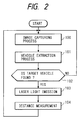
- FIG. 2 is a flowchart of procedures in the embodiment shown FIG. 1.
- FIG. 3 is a flowchart of procedures in the embodiment shown FIG. 1.
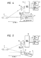
- FIG. 4 is a schematic diagram showing distance measurement method for vehicle.
- FIG. 5 is a schematic diagram showing distance measurement method for vehicle in another embodiment.
- FIG. 6 is a schematic diagram showing distance measurement method for vehicle in another embodiment.
- FIG. 7 is a schematic diagram showing distance measurement method for vehicle using modulation signal.
- FIG. 8 is a structure of another embodiment of the distance measurement apparatus for vehicle.
- FIG. 9 is a flowchart of procedures in the embodiment shown in FIG. 8.
- FIG. 10 is a schematic diagram of the distance measurement apparatus for vehicle having a mechanical mechanism for vibration protection.
- FIG. 10 is a schematic diagram of the distance measurement apparatus for vehicle having a mechanical mechanism for vibration protection.
- FIG. 11 is a schematic diagram of the distance measurement apparatus for vehicle having an electronic mechanism for vibration protection.
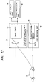
- FIG. 12 is a schematic diagram of distance measurement method for vehicle having an auto-focus mechanism.
- FIG. 13 is a schematic diagram of distance measurement method for vehicle having a light filter in the light receiving part.
- FIG. 14 is a structure of another embodiment of the distance measurement apparatus for vehicle.
- FIG. 15 is a flowchart of procedures in the embodiment shown in FIG. 14.
- FIG. 16 is a flowchart of procedures in the embodiment shown in FIG. 14.
- FIGS. 1 to 16 embodiments of the present invention are described below.
- FIG. 1 shows a structure of the apparatus of the present invention, and its procedural flow is shown in FIG. 2.
- the camera 5 used as an imaging apparatus captures the image developed in front of the driving vehicle on which the camera is installed, and the vehicle extraction part 7 extracts the image of the target vehicle 2 running forward in front of the driving vehicle.
- the light emission part 3 exposes a collimated laser beam to the extracted target object.
- the reflected light from the target vehicle 2 is detected by the light detection part 4, and the distance R from the driving vehicle to the target vehicle 2 is measured.
- an exemplary image is shown on the image display part 6.
- FIG. 2 the procedures taken in the distance measurement apparatus for vehicle defined as in FIG. 1 are shown in a flowchart.
- the image developed in front of the driving vehicle is captured by the camera 5.
- the image of the target vehicle as an object to which the distance is to be measured is extracted by the vehicle extraction part 7. If it is judged in the step 102 that the target vehicle does not exist, the step 100 is selected to go back for capturing the next image.
- a collimated laser beam is exposed to the target vehicle in the step 103, and next, the distance to the target vehicle is measured by detecting the reflected light in the step 104. After measuring the distance, going back to the step 100 and the above procedures are repeated again.
- laser beam for measuring the distance to the target vehicle, it may be allowed to use another kind of emission beams or collimated electric waves.
- the procedures down to the step 102 are common to those in FIG. 2.
- the distance to the target vehicle is measured in the step 104.
- FIG. 4 another embodiment is described below.
- the image developed in front of the driving vehicle is captured by the image sensor 13 in the camera 5, and the image of the target vehicle to which the distance is to be measured is extracted.
- a laser beam is exposed to the target vehicle 2 from the light emission part 3.
- the emitted laser beam from the light emission device 10 in the light emission apparatus 3 passes through the emission light system 11.
- the exposed laser beam is reflected on the target vehicle 2, and goes back through the detection light system 12, and finally develops an image on the image sensor 13.
- the distance x from the optical center of the detection light system 12 to the image development part on the image sensor is evaluated by the image sensor 13 and its output signal is transferred to the signal processing part 9.
- the distance R between the driving vehicle and the target vehicle 2 is evaluated by the signal processing part 9 by the following formulae for triangular surveying.
- R is the distance to the target vehicle
- B is the length of the base-line extended between the emission light system and the detection light system
- f is the focus length in the light system.
- the pixel pitch of the light detection part of the CCD camera is normally about 15 micro meter, and assuming that the length B of the base-line is 20 cm and the focus length is 5 cm, the distance R to be measured around 50 m can be estimated with about 3 m resolution.
- FIGS. 5 and 6 another embodiment is descried below.
- the components of the distance measurement apparatus for vehicle in FIG. 5 are similar to those shown in FIG. 4 except that the light emission device 10 is movable in FIG. 5 so that the light emission direction may be changed.
- the light emitted from the light emission device 10 reflected on the target vehicle, and the reflected light passes through the detection light system 12 and develops an image on the image sensor 13.
- the image sensor 13 estimates the distance x1 between the optical center of the detection light system 12 and the image development part and supplies its output signal to the signal processing part 9.
- the distance x2 between the optical center of the emission light system 11 and the light emission device 10 is evaluated.
- the distance R between the driving vehicle and the target vehicle 2 is obtained by the following formulae; where R is the distance to the target vehicle, B is the length of the base-line extended between the emission light system and the detection light system, and f is the focus length in the light system.
- the distance R to the target vehicle can be evaluated.
- FIG. 6 an exemplary image captured by the image sensor 13 is shown on the image display part 6.
- the target vehicle 2 is recognized from the image information, and a collimated laser beam is exposed to the target vehicle 2 from the light emission part 3 including the emission light system 11 and the light emission device 10.
- the exposed light from the light emission part 3 is recognized as a light spot pattern on the image developed onto the image sensor 13.
- the center position of the light spot pattern is defined on the image, and the distance between the center position of the detection light system and the center position of the light spot pattern is evaluated as the horizontal displacement Xh and the vertical displacement Xv.
- a modulation signal to the light emission device 10 is applied by the modulation signal generator 14, and the signal processing part 9 processes the input signal in responsive to the timing of modulated signals.
- the intensity of the signal supplied by the light emission device 10 is changed by turning on and off the modulation signal in the time series.
- the image information captured by the image sensor 13 in the time slot while the modulation signal is turned on and the image information captured by the image sensor 13 in the time slot while the modulation signal is turned off are compared and processed by the processes 1 and 2, respectively, in the signal processing part 9. In this way, by discriminating the reflected light from the target vehicle to which the light is emitted from the light emission device 10 from another background light, the distance to the target vehicle 2 is measured.
- This embodiment relates to a distance measurement apparatus for vehicle having a scanning light emission part 30 formed by adding a scanning range control part 31 to the embodiment described in FIG. 1.
- the scanning range is made to be wide.
- the scanning light emission part 30 scans the light in a narrow range within which the target vehicle 2 can be found in responsive to the signal supplied by the scanning range control part 31.
- the target vehicle is traced by altering the direction of the narrow-range scanning by extracting the reflected light from the target vehicle 2 by the camera 5 in the vehicle extraction part 7 and supplying the control signal from the scanning range control part 31 to the scanning light emission part 30.
- the procedures in this embodiment are shown as a flowchart in FIG. 9.
- a laser beam is exposed in a wide range.
- the reflected light is captured by the camera 5, and the procedure at the step 201 for recognition and extraction of the target vehicle is performed in the vehicle extraction part 7.
- the existence of the target vehicle is judged in the step 202, and if the target vehicle does not exist, the step 200 is taken back again.
- the light beam is scanned in a narrow range within which the target vehicle is located in the step 203.
- the distance is measured in the step 104, and the validation of the measured value of the distance is judged in the step 105.
- the step 203 is taken again for repeating above procedures.
- a series of procedures from the step 200 are performed again.
- FIGS. 10 and 11 another embodiment is described below.
- the distance measurement is performed so as to extract a clear image of the target vehicle from the image information.
- FIG. 10 a mechanical method for correcting the vibration effect on image-blurring is shown.
- a unit 18 containing the light emission part 3 and the light detection part 4 is supported by the special support mechanism 16 so as to move freely in the vertical and horizontal directions.
- an angle sensor 20 for detecting the intensity of vibrational movement in the vertical direction an angle sensor 19 for detecting the intensity of vibrational movement in the horizontal direction
- an actuator 17 for rotating the unit in the vertical direction and an actuator 15 for rotating the unit in the horizontal direction are mounted.
- a couple of angle sensors 19 and 20 detects vibrational movement.
- the actuators 15 and 17 are operated so that the vibrational movement may be compensated in order to make the emitted light from the light emission part 3 exposed stably and to make the reflected light develop an image on the image detection part stably.
- FIG. 10 what is shown as an example is a mechanism including a couple of angle sensors and a couple of actuators for compensating vibrational movement in two directions. However, it may be allowed to use three sets of angle sensors and actuators for compensating vibrational movement in three directions.
- Scanned pixels 22 are defined to be pixels in the region which are to be captured by the image sensor of the light detection part 4, and marginal pixels 31 are defined to be pixels around the scanned pixels with its number being set to be half of the number of the scanned pixels.
- the region of the scanned pixels can be shifted in vertical and horizontal directs in responsive to the control signal from the drive part 25.
- the image-blurring detection part 23 the blurring pattern in the image captured by the light detection part 4 is detected, and the control signal for compensating the vibrational movement causing the blurring effect is supplied by the scanned pixel region control part 24 to the drive part 25.
- the region of the scanned pixels 22 are moved horizontally and vertically so as to obtain a stable image.
- the light detection part including the image sensor 13 is formed as a light detection part 26 having an auto-focus mechanism using TTL (Through The Lens).
- TTL Through The Lens
- FIG. 13 another embodiment is described.
- the light emission device 10 exposing the light having a designated wave length, and a light filter 27 through which the light with the wave length using the light emission device 10 passes well is mounted before the image sensor 13 in the light detection part.
- a light filter 27 through which the light with the wave length using the light emission device 10 passes well is mounted before the image sensor 13 in the light detection part.
- an optical filter 27 instead of using the optical filter 27, it may be allowed to use an image sensor 13 sensitive to the light having a designated wave length used in the light emission device 10.
- FIG. 14 shows a structure of the apparatus of the present invention, and its procedural flow is shown in FIG. 15.
- an image display part 28 having a touch panel is used instead the image display part 26 in the embodiment shown in FIG. 1.
- FIG. 14 it may be allowed to use such pointing devices as cursor and mouse for locating a designated position on the display screen.
- FIG. 15 at first in the step 300. the image information developed in front of the driving vehicle is captured by the camera 5.
- the image displayed on the image display part with touch panel 28 is presented to the vehicle driver.
- the driver is allowed to select the target vehicle to which the distance is to be measured.
- the target vehicle to which the distance is to be measured is extracted in the step 101.
- a laser beam is emitted to the target vehicle 2, and the distance to the vehicle is measured in the step 104.
- the image information is captured by the camera 5 in the step 100, and going back to the step 101, the image of the target vehicle 2 is automatically captured by the vehicle extraction part 7, and the distance measurement is performed in the steps 103 and 104, and thus, a series of the steps 100, 101, 103 and 104 are repeated.
- FIG. 16 another procedural flow applied to the structure in FIG. 14 is described.
- a step 303 is inserted after the step 101 in FIG. 16.
- the target vehicle is presented to the vehicle driver in the step 303 by means that the display color is changed or the outline of the display pattern is accentuated in order to make it easier to distinguish the target vehicle from the background image.
- the distance to the target vehicle is measured by capturing the image developed in front of the driving vehicle by the image sensor, extracting the target vehicle to which the distance is to be measured, and exposing a laser light collimated toward to target vehicle, it will be appreciated that the target vehicle is recognized exactly and that the distance to the target vehicle can be measured precisely, even in case of co-existence of other obstacle objects around the vehicles.
Landscapes
- Physics & Mathematics (AREA)
- Engineering & Computer Science (AREA)
- General Physics & Mathematics (AREA)
- Computer Networks & Wireless Communication (AREA)
- Electromagnetism (AREA)
- Radar, Positioning & Navigation (AREA)
- Remote Sensing (AREA)
- Optical Radar Systems And Details Thereof (AREA)
- Measurement Of Optical Distance (AREA)
- Traffic Control Systems (AREA)
Abstract
Description
- The present invention relates to a distance measurement apparatus for vehicle, specifically to an apparatus for measuring the distance between the driving vehicle itself and the target object by using an imaging apparatus such as an image sensor and a radar.
- Conventionally, there has been developed a system for navigating a driving vehicle so that the distance to the obstacle objects around it may be kept in a designate value and/or that the collision to the obstacle objects, both by means of measuring the distance to the obstacle object, for example, a vehicle running in front of the driving vehicle. In such a vehicle navigation system, it is an important goal to establish how accurately the distance to the target object is measured in various field conditions. In order to solve this problem, in the prior art such as Japanese Laid-Open Patent Application No. 4-262500 (1992), what is disclosed is an apparatus measuring the distance to the target object with a couple of image sensors being arrange so as to be apart from each other in a designated base-line distance by triangular surveying. In Japanese Patent Publication No. 61-006349 (1986), what is disclosed is a radar apparatus measuring the distance to the target object and its change rate, that is, relative velocity, by measuring the time difference between the signal emission and the reflected signal receiving by using laser light or electric wave.
- However, in case of the method for measuring the distance to the target object by triangular surveying with a couple of image sensors, it is difficult to extract the stable image of the target object from the output signal from the image sensor when the lighting environment changes too much due to the weather changes, the time slot in day or night and the driving way condition such as in tunnel. Therefore, there is a problem that the accuracy of the measurement of the distance to the target object deteriorates. On the other hand, in case of the method of measuring the distance to the target object by measuring the time difference by using light or electric wave, if there exist reflective obstacle such as other vehicles running beside or around than the target objects, there is a problem that it is difficult to distinguish which reflected beams can be used for the measurement of the exact distance to the target object.
- An object of the present invention is to provide a distance measurement apparatus for vehicle which enables a highly accurate measurement of the distance to the target object such as a vehicle running forward even in the driving way condition changing every moment, and furthermore that enables the measurement of the exact distance to the target object so as to be distinguished among the obstacle objects.
- The above object can be established by the distance measurement apparatus for vehicle having the following means;
a means for measuring the distance to the target object by capturing the image projected in front of the vehicle on which imaging apparatus such as image sensor and extracting the target object from the image information to which the distance is to be measured, and by exposing a laser light focused in a narrow range in the direction to the target object;
a means for measuring the distance to the target object by angular surveying by receiving the reflected beam from the target object by the imaging apparatus;
a means for determining the target object to which the distance is to be measured by exposing laser beam in a wide range and receiving the reflected light by the imaging apparatus, and for measuring the distance to the target object by exposing a collimated laser beam in a narrow range so as to be directed to the target object; and
a means for displaying the image captured by the imaging apparatus to the driver of the vehicle and allowing the driver to specify the target object to which the distan ce is to be measured, and for measuring the distance by exposing the laser beam to the target object. - In order to determine the target object to which the distance is to be measured according to the image information captured by the imaging apparatus and to measure the distance to the target object by exposing a collimated laser beam in a narrow range to the target object, the distance measurement apparatus for vehicle can reject the laser beam reflected by the obstacle objects, distinguish the target object from the obstacle objects and measure the exact distance to the target object accurately.
- FIG. 1 is a structure of one embodiment of the distance measurement apparatus for vehicle.
FIG. 2 is a flowchart of procedures in the embodiment shown FIG. 1.
FIG. 3 is a flowchart of procedures in the embodiment shown FIG. 1.
FIG. 4 is a schematic diagram showing distance measurement method for vehicle.
FIG. 5 is a schematic diagram showing distance measurement method for vehicle in another embodiment.
FIG. 6 is a schematic diagram showing distance measurement method for vehicle in another embodiment.
FIG. 7 is a schematic diagram showing distance measurement method for vehicle using modulation signal.
FIG. 8 is a structure of another embodiment of the distance measurement apparatus for vehicle.
FIG. 9 is a flowchart of procedures in the embodiment shown in FIG. 8.
FIG. 10 is a schematic diagram of the distance measurement apparatus for vehicle having a mechanical mechanism for vibration protection.
FIG. 11 is a schematic diagram of the distance measurement apparatus for vehicle having an electronic mechanism for vibration protection.
FIG. 12 is a schematic diagram of distance measurement method for vehicle having an auto-focus mechanism.
FIG. 13 is a schematic diagram of distance measurement method for vehicle having a light filter in the light receiving part.
FIG. 14 is a structure of another embodiment of the distance measurement apparatus for vehicle.
FIG. 15 is a flowchart of procedures in the embodiment shown in FIG. 14.
FIG. 16 is a flowchart of procedures in the embodiment shown in FIG. 14. - By referring to FIGS. 1 to 16, embodiments of the present invention are described below.
- FIG. 1 shows a structure of the apparatus of the present invention, and its procedural flow is shown in FIG. 2. In FIG. 1, the
camera 5 used as an imaging apparatus captures the image developed in front of the driving vehicle on which the camera is installed, and thevehicle extraction part 7 extracts the image of thetarget vehicle 2 running forward in front of the driving vehicle. In responsive to the signal from the light emissiondirection control part 7, thelight emission part 3 exposes a collimated laser beam to the extracted target object. The reflected light from thetarget vehicle 2 is detected by thelight detection part 4, and the distance R from the driving vehicle to thetarget vehicle 2 is measured. In FIG. 1, an exemplary image is shown on theimage display part 6. What shown in this example is that a collimated laser beam is exposed from thelight emission part 3 to thetarget vehicle 2 in the display image and that the reflected light is detected by thelight detection part 4. In FIG. 2, the procedures taken in the distance measurement apparatus for vehicle defined as in FIG. 1 are shown in a flowchart. At first, in thestep 100, the image developed in front of the driving vehicle is captured by thecamera 5. In thestep 101, the image of the target vehicle as an object to which the distance is to be measured is extracted by thevehicle extraction part 7. If it is judged in thestep 102 that the target vehicle does not exist, thestep 100 is selected to go back for capturing the next image. If the target vehicle exists, a collimated laser beam is exposed to the target vehicle in thestep 103, and next, the distance to the target vehicle is measured by detecting the reflected light in thestep 104. After measuring the distance, going back to thestep 100 and the above procedures are repeated again. Though what is shown in this embodiment is an example using laser beam for measuring the distance to the target vehicle, it may be allowed to use another kind of emission beams or collimated electric waves. - By referring to FIG. 3, another procedures applicable to the apparatus structure identical to that in FIG. 1 are described. The procedures down to the
step 102 are common to those in FIG. 2. After exposing a collimated laser beam to the target vehicle in thestep 103, the distance to the target vehicle is measured in thestep 104. As it is possible to suppose that the distance between the driving vehicle and the vehicle running forward and its time change is limited to a definite value, it can be judged comprehensively in thestep 105 whether the measured value of the distance is valid or not. If it is so, the laser beam is judged to be exposed properly to the target vehicle, and therefore, the procedures from thestep 103 to thestep 105 are repeated. In case that thestep 105 judges that the measured value is not valid and that the laser beam is not exposed to the target vehicle, going back to thestep 100, the procedures from thestep 100 for capturing the image to thestep 103 for exposing the laser beam are repeated. - By referring to FIG. 4, another embodiment is described below. Similarly to the embodiment shown in FIGS. 1 and 2, the image developed in front of the driving vehicle is captured by the
image sensor 13 in thecamera 5, and the image of the target vehicle to which the distance is to be measured is extracted. Next, a laser beam is exposed to thetarget vehicle 2 from thelight emission part 3. The emitted laser beam from thelight emission device 10 in thelight emission apparatus 3 passes through theemission light system 11. The exposed laser beam is reflected on thetarget vehicle 2, and goes back through thedetection light system 12, and finally develops an image on theimage sensor 13. The distance x from the optical center of thedetection light system 12 to the image development part on the image sensor is evaluated by theimage sensor 13 and its output signal is transferred to thesignal processing part 9. The distance R between the driving vehicle and thetarget vehicle 2 is evaluated by thesignal processing part 9 by the following formulae for triangular surveying.
where
R is the distance to the target vehicle,
B is the length of the base-line extended between the emission light system and the detection light system, and
f is the focus length in the light system. - For example, in case of using a CCD camera for the
image sensor 13, the pixel pitch of the light detection part of the CCD camera is normally about 15 micro meter, and assuming that the length B of the base-line is 20 cm and the focus length is 5 cm, the distance R to be measured around 50 m can be estimated with about 3 m resolution. - By referring to FIGS. 5 and 6, another embodiment is descried below. The components of the distance measurement apparatus for vehicle in FIG. 5 are similar to those shown in FIG. 4 except that the
light emission device 10 is movable in FIG. 5 so that the light emission direction may be changed. The light emitted from thelight emission device 10 reflected on the target vehicle, and the reflected light passes through thedetection light system 12 and develops an image on theimage sensor 13. Theimage sensor 13 estimates the distance x1 between the optical center of thedetection light system 12 and the image development part and supplies its output signal to thesignal processing part 9. In addition, the distance x2 between the optical center of theemission light system 11 and thelight emission device 10 is evaluated. Based on the evaluated value x1 and x2, the distance R between the driving vehicle and thetarget vehicle 2 is obtained by the following formulae;
where
R is the distance to the target vehicle,
B is the length of the base-line extended between the emission light system and the detection light system, and
f is the focus length in the light system. - In the similar manner, not only in case that the
light emission device 10 is movable, but also in case that theemission light system 11 is movable, or in case that both of thelight emission device 10 and theemission light system 11 are movable, the distance R to the target vehicle can be evaluated. - In FIG. 6, an exemplary image captured by the
image sensor 13 is shown on theimage display part 6. Thetarget vehicle 2 is recognized from the image information, and a collimated laser beam is exposed to thetarget vehicle 2 from thelight emission part 3 including theemission light system 11 and thelight emission device 10. The exposed light from thelight emission part 3 is recognized as a light spot pattern on the image developed onto theimage sensor 13. The center position of the light spot pattern is defined on the image, and the distance between the center position of the detection light system and the center position of the light spot pattern is evaluated as the horizontal displacement Xh and the vertical displacement Xv. By obtaining the root of the sum of the square of Xh and the square of Xv, with angular surveying similar to theformulae 2, the distance to the target vehicle is evaluated. - By referring to FIG. 7, another embodiment is described below. In the distance measurement apparatus for vehicle using the
light emission device 10 and theimage sensor 13 as described in FIGS. 1 and 4, a modulation signal to thelight emission device 10 is applied by the modulation signal generator 14, and thesignal processing part 9 processes the input signal in responsive to the timing of modulated signals. For example, as shown at the lower left part in FIG. 7, the intensity of the signal supplied by thelight emission device 10 is changed by turning on and off the modulation signal in the time series. The image information captured by theimage sensor 13 in the time slot while the modulation signal is turned on and the image information captured by theimage sensor 13 in the time slot while the modulation signal is turned off are compared and processed by theprocesses signal processing part 9. In this way, by discriminating the reflected light from the target vehicle to which the light is emitted from thelight emission device 10 from another background light, the distance to thetarget vehicle 2 is measured. - By referring to FIGS. 8 and 9, another embodiment is described below. This embodiment relates to a distance measurement apparatus for vehicle having a scanning
light emission part 30 formed by adding a scanningrange control part 31 to the embodiment described in FIG. 1. In case that the direction in which the target vehicle is located in front of the driving vehicle is not exactly forecastable, the scanning range is made to be wide. In this case, by using the light emitted from the scanninglight emission part 30, the reflected light is captured by thecamera 5, and the existence of thetarget vehicle 2 is detected by thevehicle extraction part 7. After detecting the existence of thetarget vehicle 2, the scanninglight emission part 30 scans the light in a narrow range within which thetarget vehicle 2 can be found in responsive to the signal supplied by the scanningrange control part 31. - For following the movement of the target vehicle, the target vehicle is traced by altering the direction of the narrow-range scanning by extracting the reflected light from the
target vehicle 2 by thecamera 5 in thevehicle extraction part 7 and supplying the control signal from the scanningrange control part 31 to the scanninglight emission part 30. The procedures in this embodiment are shown as a flowchart in FIG. 9. At first, in thestep 200, a laser beam is exposed in a wide range. The reflected light is captured by thecamera 5, and the procedure at thestep 201 for recognition and extraction of the target vehicle is performed in thevehicle extraction part 7. The existence of the target vehicle is judged in thestep 202, and if the target vehicle does not exist, thestep 200 is taken back again. If the target vehicle exists, the light beam is scanned in a narrow range within which the target vehicle is located in thestep 203. In the similar manner as described in FIG. 3, the distance is measured in thestep 104, and the validation of the measured value of the distance is judged in thestep 105. In case that the measured value of the distance is valid, thestep 203 is taken again for repeating above procedures. In case that the value is not valid, a series of procedures from thestep 200 are performed again. - By referring to FIGS. 10 and 11, another embodiment is described below. In this embodiment, by adding such a function for preventing image-blurring due to the vibration of the driving vehicle as used in handy video cameras to the above described embodiments of the distance measurement apparatus for vehicle, the distance measurement is performed so as to extract a clear image of the target vehicle from the image information. In FIG. 10, a mechanical method for correcting the vibration effect on image-blurring is shown. A
unit 18 containing thelight emission part 3 and thelight detection part 4 is supported by thespecial support mechanism 16 so as to move freely in the vertical and horizontal directions. In theunit 17, anangle sensor 20 for detecting the intensity of vibrational movement in the vertical direction, anangle sensor 19 for detecting the intensity of vibrational movement in the horizontal direction, anactuator 17 for rotating the unit in the vertical direction and anactuator 15 for rotating the unit in the horizontal direction are mounted. When the vibrational force is applied to the distance measurement apparatus for vehicle having the light emission part and the light detection part, a couple ofangle sensors actuators light emission part 3 exposed stably and to make the reflected light develop an image on the image detection part stably. In FIG. 10, what is shown as an example is a mechanism including a couple of angle sensors and a couple of actuators for compensating vibrational movement in two directions. However, it may be allowed to use three sets of angle sensors and actuators for compensating vibrational movement in three directions. - In the embodiment shown in FIG. 11, an electronic method for correcting the vibration effect on image-blurring is shown. Scanned
pixels 22 are defined to be pixels in the region which are to be captured by the image sensor of thelight detection part 4, andmarginal pixels 31 are defined to be pixels around the scanned pixels with its number being set to be half of the number of the scanned pixels. The region of the scanned pixels can be shifted in vertical and horizontal directs in responsive to the control signal from thedrive part 25. In the image-blurringdetection part 23, the blurring pattern in the image captured by thelight detection part 4 is detected, and the control signal for compensating the vibrational movement causing the blurring effect is supplied by the scanned pixel region controlpart 24 to thedrive part 25. In responsive to the drive signal from thedrive part 25, the region of the scannedpixels 22 are moved horizontally and vertically so as to obtain a stable image. - By referring to FIG. 12, another embodiment is described below. In the apparatus for measuring the distance by emitting the light from the
light emission part 3 and detecting the reflected light from the target vehicle by theimage sensor 13, the light detection part including theimage sensor 13 is formed as alight detection part 26 having an auto-focus mechanism using TTL (Through The Lens). In either case that the distance to thetarget object 2 is short or long, a sharp image of thetarget vehicle 2 is developed on theimage sensor 13 with the auto-focus mechanism. By adding a zooming function to thelight detection part 26 having an auto-focus mechanism, the size of the image of thetarget vehicle 2 developed on theimage sensor 13 is controlled so that the image of thetarget vehicle 2 may be captured accurately. - By referring to FIG. 13, another embodiment is described. In the distance measurement apparatus for vehicle using the
light emission part 3 and theimage sensor 13, thelight emission device 10 exposing the light having a designated wave length, and alight filter 27 through which the light with the wave length using thelight emission device 10 passes well is mounted before theimage sensor 13 in the light detection part. In FIG. 13, what is shown as an example is anoptical filter 27. Instead of using theoptical filter 27, it may be allowed to use animage sensor 13 sensitive to the light having a designated wave length used in thelight emission device 10. - Referring to FIGS. 14 and 15, another embodiment is described. FIG. 14 shows a structure of the apparatus of the present invention, and its procedural flow is shown in FIG. 15. In the structure in FIG. 14, an
image display part 28 having a touch panel is used instead theimage display part 26 in the embodiment shown in FIG. 1. Though an example of the image display part having a touch panel is shown in FIG. 14, it may be allowed to use such pointing devices as cursor and mouse for locating a designated position on the display screen. As shown in FIG. 15, at first in thestep 300. the image information developed in front of the driving vehicle is captured by thecamera 5. Next in thestep 301, the image displayed on the image display part withtouch panel 28 is presented to the vehicle driver. In thestep 302, the driver is allowed to select the target vehicle to which the distance is to be measured. Based on the input signal by the driver on the image display part withtouch panel 28, the target vehicle to which the distance is to be measured is extracted in thestep 101. In thestep 103, a laser beam is emitted to thetarget vehicle 2, and the distance to the vehicle is measured in thestep 104. Now that the target vehicle is specified, the image information is captured by thecamera 5 in thestep 100, and going back to thestep 101, the image of thetarget vehicle 2 is automatically captured by thevehicle extraction part 7, and the distance measurement is performed in thesteps steps - By referring to FIG. 16, another procedural flow applied to the structure in FIG. 14 is described. In contrast to the flow in FIG. 15, a
step 303 is inserted after thestep 101 in FIG. 16. After extracting the target vehicle to which the distance is to be measured in thestep 101, the target vehicle is presented to the vehicle driver in thestep 303 by means that the display color is changed or the outline of the display pattern is accentuated in order to make it easier to distinguish the target vehicle from the background image. - According to the present invention as described above, as the distance to the target vehicle is measured by capturing the image developed in front of the driving vehicle by the image sensor, extracting the target vehicle to which the distance is to be measured, and exposing a laser light collimated toward to target vehicle, it will be appreciated that the target vehicle is recognized exactly and that the distance to the target vehicle can be measured precisely, even in case of co-existence of other obstacle objects around the vehicles.
Claims (12)
- A distance measurement apparatus for vehicle comprising
an image capturing apparatus for capturing an image around a driving vehicle;
a signal processing part for extracting a target vehicle to which a distance is to be measured from an image information;
a light emission part for emitting a laser beam collimated forward to said extracted target vehicle; and
a distance detection part for evaluating a distance by detecting a reflected laser beam from said target vehicle. - A distance measurement apparatus for vehicle in Claim 1, wherein
a first procedure for extracting a target vehicle is taken,
a second procedure for emitting a emitting a laser beam collimated forward to a target vehicle is taken next,
a third procedure for measuring a distance to said target vehicle by detecting a reflected laser beam from said target vehicle and judging a validity of a measured value of said distance is taken next,
if said measured value is valid, said second procedure to said third procedure are repeated, and
if otherwise, said first procedure to said third procedure are repeated. - A distance measurement apparatus for vehicle comprising
an image capturing apparatus for capturing an image around a driving vehicle;
a signal processing part for extracting a target vehicle to which a distance is to be measured from an image information;
a light emission apparatus for emitting a laser beam collimated forward to said extracted target vehicle; and
a means for measuring a distance from a substantial center of a detection light system of a part where an image is developed on said image capturing apparatus by a reflected laser beam from said target vehicle; and
a means for measuring a distance to said target vehicle by using a position information of a emission light system, a detection light system and a development part on an image sensor of said image capturing apparatus. - A distance measurement apparatus for vehicle in Claim 3, further comprising
a light emission part enabling to change freely a direction in which a laser beam is emitted. - A distance measurement apparatus for vehicle in Claim 3, wherein
an intensity and a phase of a laser beam is changed by applying a designated modulation signal to a light emission apparatus;
an image information captured by said image capturing apparatus is processed in responsive to said modulation signal; and
a reflected laser beam is distinguished from a background light. - A distance measurement apparatus for vehicle comprising
a light emission apparatus for emitting a laser beam with a variable emission range;
a signal processing part for detecting a reflected laser beam when a laser beam is emitted from said light emission apparatus in a wide range and for extracting a target vehicle; and
a measurement apparatus for measuring a distance to said target vehicle by emitting a laser beam collimated to said target vehicle from said light emission apparatus and detecting a reflected laser beam from said target vehicle. - A distance measurement apparatus for vehicle in either of Claims 1 to 6, wherein
a unit for emitting and detecting a laser beam has
a support mechanism;
a sensor for detecting a vibration movement of a driving vehicle; and
an actuator for compensating said detected vibration
movement;
and
a mechanism for measuring a distance by emitting a laser beam in a stable direction, not subject to a vibration movement of a driving vehicle and detecting a reflected laser beam. - A distance measurement apparatus for vehicle in Claim 7, further comprising
a mechanism for defining a marginal pixel region around a scanned pixel region in an image sensor of a light detection part, and for allowing said scanned pixel region to be moved freely in vertical and horizontal direction; and
an apparatus for detecting a image-blurring effect from an image information captured on said scanned pixel region,
wherein
a control function for shifting said scanned pixel region on said image sensor so as to compensate a vibration movement causing said image-blurring effect due to a vibration of a driving vehicle. - A distance measurement apparatus for vehicle in Claim 7 or 8, wherein
a light detection part has an auto-focus mechanism; and
an image of a target vehicle is developed in focus on an image sensor. - A distance measurement apparatus for vehicle in either of Claims 7 to 9, wherein
an optical filter through which a light having a wave length identical to a light emitted from a light emission part passes well is installed in a light detection part. - A distance measurement apparatus for vehicle in either of Claims 7 to 10, wherein
an image sensor using a device which detects sensitively a light having a wave length identical to a light emitted from a light emission part passes well is installed in a light detection part. - A distance measurement apparatus for vehicle comprising
an input means such as a touch panel is formed in a display part for an image captured by a camera and presented to a vehicle driver; and
allowing said vehicle driver to select an target vehicle to which a distance is measured by means of said image captured said camera; and
measuring said distance to said target vehicle by emitting a laser beam collimated to said target vehicle selected by said vehicle driver and by detecting an reflected light from said target vehicle.
Applications Claiming Priority (2)
| Application Number | Priority Date | Filing Date | Title |
|---|---|---|---|
| JP12729494A JP3240835B2 (en) | 1994-06-09 | 1994-06-09 | Vehicle distance measuring device |
| JP127294/94 | 1994-06-09 |
Publications (2)
| Publication Number | Publication Date |
|---|---|
| EP0686857A2 true EP0686857A2 (en) | 1995-12-13 |
| EP0686857A3 EP0686857A3 (en) | 1996-03-20 |
Family
ID=14956408
Family Applications (1)
| Application Number | Title | Priority Date | Filing Date |
|---|---|---|---|
| EP95108772A Withdrawn EP0686857A3 (en) | 1994-06-09 | 1995-06-07 | Rangefinder for vehicles |
Country Status (4)
| Country | Link |
|---|---|
| US (1) | US5699149A (en) |
| EP (1) | EP0686857A3 (en) |
| JP (1) | JP3240835B2 (en) |
| KR (1) | KR100352423B1 (en) |
Cited By (9)
| Publication number | Priority date | Publication date | Assignee | Title |
|---|---|---|---|---|
| WO1997028457A1 (en) * | 1996-01-30 | 1997-08-07 | Robert Bosch Gmbh | Range and/or position measurement equipment |
| EP1308752A3 (en) * | 2001-11-02 | 2003-11-26 | Fuji Jukogyo Kabushiki Kaisha | Monitoring system of the outside of a vehicle and method therefore |
| EP1684094A2 (en) | 2005-01-24 | 2006-07-26 | Robert Bosch Gmbh | Method of optical triangulation for determining distance in automotive applications |
| DE102006041930A1 (en) * | 2006-09-07 | 2008-03-27 | Bayerische Motoren Werke Ag | Driver assistance system with object recognition |
| EP2568313A1 (en) * | 2011-09-07 | 2013-03-13 | Audi AG | Method for detecting an object near a motor vehicle |
| EP2605041A1 (en) * | 2011-12-13 | 2013-06-19 | Robert Bosch Gmbh | Handheld range finder |
| WO2013087280A1 (en) * | 2011-12-13 | 2013-06-20 | Robert Bosch Gmbh | Hand‑held distance‑measuring device |
| EP1480057A3 (en) * | 2001-10-18 | 2014-01-22 | Fuji Jukogyo Kabushiki Kaisha | Monitoring system of the outside of a vehicle and method therefore |
| CN103293007B (en) * | 2013-06-09 | 2016-01-20 | 湖州金博电子技术有限公司 | A kind of agricultural vehicle performance detection method and detecting instrument thereof |
Families Citing this family (62)
| Publication number | Priority date | Publication date | Assignee | Title |
|---|---|---|---|---|
| US6822563B2 (en) | 1997-09-22 | 2004-11-23 | Donnelly Corporation | Vehicle imaging system with accessory control |
| US5877897A (en) | 1993-02-26 | 1999-03-02 | Donnelly Corporation | Automatic rearview mirror, vehicle lighting control and vehicle interior monitoring system using a photosensor array |
| US6891563B2 (en) | 1996-05-22 | 2005-05-10 | Donnelly Corporation | Vehicular vision system |
| US7655894B2 (en) | 1996-03-25 | 2010-02-02 | Donnelly Corporation | Vehicular image sensing system |
| US5889582A (en) * | 1997-03-10 | 1999-03-30 | Virtek Vision Corporation | Image-directed active range finding system |
| US5837994C1 (en) * | 1997-04-02 | 2001-10-16 | Gentex Corp | Control system to automatically dim vehicle head lamps |
| US7115571B1 (en) * | 2000-06-16 | 2006-10-03 | Myelos Corporation | Retro-inverso peptides derived from interleukin-3 |
| DE10025678B4 (en) | 2000-05-24 | 2006-10-19 | Daimlerchrysler Ag | Camera-based precrash detection system |
| US6502053B1 (en) * | 2000-06-12 | 2002-12-31 | Larry Hardin | Combination passive and active speed detection system |
| JP4040825B2 (en) * | 2000-06-12 | 2008-01-30 | 富士フイルム株式会社 | Image capturing apparatus and distance measuring method |
| DE10055510B4 (en) * | 2000-11-09 | 2004-02-26 | Hilti Ag | Optoelectronic laser distance meter |
| JP4201155B2 (en) * | 2000-11-22 | 2008-12-24 | 道弘 観音寺 | Inter-vehicle distance alarm device |
| JP4595197B2 (en) * | 2000-12-12 | 2010-12-08 | 株式会社デンソー | Distance measuring device |
| AU2003225228A1 (en) | 2002-05-03 | 2003-11-17 | Donnelly Corporation | Object detection system for vehicle |
| US6918538B2 (en) * | 2002-12-18 | 2005-07-19 | Symbol Technologies, Inc. | Image scanning device having a system for determining distance to a target |
| US7066388B2 (en) * | 2002-12-18 | 2006-06-27 | Symbol Technologies, Inc. | System and method for verifying RFID reads |
| US20070019181A1 (en) * | 2003-04-17 | 2007-01-25 | Sinclair Kenneth H | Object detection system |
| US8139141B2 (en) * | 2004-01-28 | 2012-03-20 | Microsoft Corporation | Single chip red, green, blue, distance (RGB-Z) sensor |
| US20060085993A1 (en) * | 2004-02-20 | 2006-04-27 | Frankowiak Jerome P | Folding framing square |
| US7161664B2 (en) * | 2004-04-13 | 2007-01-09 | Electronic Scripting Products, Inc. | Apparatus and method for optical determination of intermediate distances |
| US7526103B2 (en) | 2004-04-15 | 2009-04-28 | Donnelly Corporation | Imaging system for vehicle |
| US7113270B2 (en) * | 2004-06-18 | 2006-09-26 | Electronics Scripting Products, Inc. | Determination of an orientation parameter of an elongate object with a scan beam apparatus |
| US7881496B2 (en) | 2004-09-30 | 2011-02-01 | Donnelly Corporation | Vision system for vehicle |
| JP4557819B2 (en) * | 2005-06-21 | 2010-10-06 | アルパイン株式会社 | Vehicle periphery information providing device |
| US7933001B2 (en) * | 2005-07-11 | 2011-04-26 | Kabushiki Kaisha Topcon | Geographic data collecting system |
| JP4977339B2 (en) * | 2005-07-11 | 2012-07-18 | 株式会社トプコン | Geographic data collection device |
| JP4571071B2 (en) * | 2005-12-19 | 2010-10-27 | アルパイン株式会社 | On-vehicle other vehicle detection device |
| JP5061767B2 (en) * | 2006-08-10 | 2012-10-31 | 日産自動車株式会社 | Image processing apparatus and image processing method |
| US7972045B2 (en) | 2006-08-11 | 2011-07-05 | Donnelly Corporation | Automatic headlamp control system |
| US7554653B2 (en) * | 2006-12-01 | 2009-06-30 | Trimble Ab | Multitarget |
| JP2008164302A (en) | 2006-12-26 | 2008-07-17 | Yamaha Corp | Intervehicular distance measuring system |
| JP5150307B2 (en) * | 2008-03-03 | 2013-02-20 | 株式会社トプコン | Geographic data collection device |
| JP5150310B2 (en) * | 2008-03-04 | 2013-02-20 | 株式会社トプコン | Geographic data collection device |
| KR100940035B1 (en) * | 2008-04-17 | 2010-02-04 | (주)인펙비전 | School zone monitoring system |
| JP5698480B2 (en) | 2010-09-02 | 2015-04-08 | 株式会社トプコン | Measuring method and measuring device |
| JP6009753B2 (en) * | 2011-10-26 | 2016-10-19 | 株式会社トプコン | Image measuring device |
| US10457209B2 (en) | 2012-02-22 | 2019-10-29 | Magna Electronics Inc. | Vehicle vision system with multi-paned view |
| CN108919294B (en) * | 2013-11-20 | 2022-06-14 | 新唐科技日本株式会社 | Ranging camera system and solid-state imaging element |
| KR101671993B1 (en) | 2014-08-01 | 2016-11-03 | 부경대학교 산학협력단 | Safety system for vehicle |
| WO2016027289A1 (en) | 2014-08-21 | 2016-02-25 | 三菱電機株式会社 | Drive assist device, drive assist method, and program |
| US10620300B2 (en) | 2015-08-20 | 2020-04-14 | Apple Inc. | SPAD array with gated histogram construction |
| KR101773020B1 (en) | 2015-09-25 | 2017-09-12 | 영남대학교 산학협력단 | Ladar sensor device |
| DE112015007054B4 (en) | 2015-11-20 | 2019-11-28 | Mitsubishi Electric Corp. | TRAVEL SUPPORT DEVICE, TRAVEL SUPPORT SYSTEM, TRAVEL SUPPORT PROCEDURE AND TRAVEL SUPPORT PROGRAM |
| US10823826B2 (en) | 2016-06-14 | 2020-11-03 | Stmicroelectronics, Inc. | Adaptive laser power and ranging limit for time of flight sensor |
| US20180341009A1 (en) | 2016-06-23 | 2018-11-29 | Apple Inc. | Multi-range time of flight sensing |
| US10275610B2 (en) | 2016-11-28 | 2019-04-30 | Stmicroelectronics, Inc. | Time of flight sensing for providing security and power savings in electronic devices |
| WO2018100648A1 (en) * | 2016-11-29 | 2018-06-07 | マクセル株式会社 | Optical scanning device and optical rangefinder |
| WO2019005260A1 (en) | 2017-06-29 | 2019-01-03 | Apple Inc. | Time-of-flight depth mapping with parallax compensation |
| KR102050632B1 (en) | 2017-08-02 | 2019-12-03 | 주식회사 에스오에스랩 | Multi-channel LiDAR sensor module |
| US10955552B2 (en) | 2017-09-27 | 2021-03-23 | Apple Inc. | Waveform design for a LiDAR system with closely-spaced pulses |
| WO2019125349A1 (en) | 2017-12-18 | 2019-06-27 | Montrose Laboratories Llc | Time-of-flight sensing using an addressable array of emitters |
| KR102059244B1 (en) * | 2017-12-20 | 2019-12-24 | 주식회사 에스오에스랩 | Apparatus for Light Detection and Ranging |
| KR102448164B1 (en) | 2018-07-20 | 2022-09-28 | 현대모비스 주식회사 | Vehicle radar control device and method |
| WO2020167338A1 (en) | 2019-02-11 | 2020-08-20 | Apple Inc. | Depth sensing using a sparse array of pulsed beams |
| US11500094B2 (en) | 2019-06-10 | 2022-11-15 | Apple Inc. | Selection of pulse repetition intervals for sensing time of flight |
| US11555900B1 (en) | 2019-07-17 | 2023-01-17 | Apple Inc. | LiDAR system with enhanced area coverage |
| JP7259660B2 (en) * | 2019-09-10 | 2023-04-18 | 株式会社デンソー | Image registration device, image generation system and image registration program |
| US11733359B2 (en) * | 2019-12-03 | 2023-08-22 | Apple Inc. | Configurable array of single-photon detectors |
| US12442926B2 (en) | 2021-02-04 | 2025-10-14 | Apple Inc. | Time-of-flight depth sensing with improved linearity |
| US12196860B2 (en) | 2021-03-02 | 2025-01-14 | Apple Inc. | Depth sensor calibration using internal reflections |
| US11681028B2 (en) | 2021-07-18 | 2023-06-20 | Apple Inc. | Close-range measurement of time of flight using parallax shift |
| US20230177976A1 (en) * | 2021-12-08 | 2023-06-08 | J.J. Keller & Associates, Inc. | Commercial Vehicle Back-Up Trainer and Method |
Citations (2)
| Publication number | Priority date | Publication date | Assignee | Title |
|---|---|---|---|---|
| JPS616349A (en) | 1984-06-18 | 1986-01-13 | 津田駒工業株式会社 | Drum type weft yarn storage apparatus |
| JPH04262500A (en) | 1991-02-08 | 1992-09-17 | Mitsubishi Electric Corp | Inter-vehicle distance detector |
Family Cites Families (6)
| Publication number | Priority date | Publication date | Assignee | Title |
|---|---|---|---|---|
| US4453083A (en) * | 1981-10-26 | 1984-06-05 | Betriebsforschungsinstitut Vdeh Institut Fur Angewandte Forschung Gmbh | Apparatus for the determination of the position of a surface |
| US4833469A (en) * | 1987-08-03 | 1989-05-23 | David Constant V | Obstacle proximity detector for moving vehicles and method for use thereof |
| FR2676284B1 (en) * | 1991-05-07 | 1994-12-02 | Peugeot | METHOD FOR DETECTING OBSTACLES PRESENT IN FRONT OF A MOTOR VEHICLE AND DEVICE FOR CARRYING OUT SUCH A METHOD. |
| FR2684763B1 (en) * | 1991-12-10 | 1995-02-17 | Peugeot | INTEGRATED DEVICE FOR THE DETECTION AND IDENTIFICATION OF OBSTACLES ON BOARD, PARTICULARLY ON BOARD OF A MOTOR VEHICLE. |
| JP2800531B2 (en) * | 1992-02-28 | 1998-09-21 | 三菱電機株式会社 | Obstacle detection device for vehicles |
| JP3263699B2 (en) * | 1992-12-22 | 2002-03-04 | 三菱電機株式会社 | Driving environment monitoring device |
-
1994
- 1994-06-09 JP JP12729494A patent/JP3240835B2/en not_active Expired - Fee Related
-
1995
- 1995-06-07 EP EP95108772A patent/EP0686857A3/en not_active Withdrawn
- 1995-06-09 KR KR1019950015201A patent/KR100352423B1/en not_active Expired - Fee Related
- 1995-06-09 US US08/489,293 patent/US5699149A/en not_active Expired - Fee Related
Patent Citations (2)
| Publication number | Priority date | Publication date | Assignee | Title |
|---|---|---|---|---|
| JPS616349A (en) | 1984-06-18 | 1986-01-13 | 津田駒工業株式会社 | Drum type weft yarn storage apparatus |
| JPH04262500A (en) | 1991-02-08 | 1992-09-17 | Mitsubishi Electric Corp | Inter-vehicle distance detector |
Cited By (12)
| Publication number | Priority date | Publication date | Assignee | Title |
|---|---|---|---|---|
| WO1997028457A1 (en) * | 1996-01-30 | 1997-08-07 | Robert Bosch Gmbh | Range and/or position measurement equipment |
| EP1480057A3 (en) * | 2001-10-18 | 2014-01-22 | Fuji Jukogyo Kabushiki Kaisha | Monitoring system of the outside of a vehicle and method therefore |
| EP1308752A3 (en) * | 2001-11-02 | 2003-11-26 | Fuji Jukogyo Kabushiki Kaisha | Monitoring system of the outside of a vehicle and method therefore |
| EP1684094A2 (en) | 2005-01-24 | 2006-07-26 | Robert Bosch Gmbh | Method of optical triangulation for determining distance in automotive applications |
| EP1684094A3 (en) * | 2005-01-24 | 2006-10-18 | Robert Bosch Gmbh | Method of optical triangulation for determining distance in automotive applications |
| DE102006041930A1 (en) * | 2006-09-07 | 2008-03-27 | Bayerische Motoren Werke Ag | Driver assistance system with object recognition |
| US8093999B2 (en) | 2006-09-07 | 2012-01-10 | Bayerische Motoren Werke Aktiengesellschaft | Driver assistance system and method with object detection facility |
| EP2568313A1 (en) * | 2011-09-07 | 2013-03-13 | Audi AG | Method for detecting an object near a motor vehicle |
| EP2605041A1 (en) * | 2011-12-13 | 2013-06-19 | Robert Bosch Gmbh | Handheld range finder |
| WO2013087280A1 (en) * | 2011-12-13 | 2013-06-20 | Robert Bosch Gmbh | Hand‑held distance‑measuring device |
| US8970825B2 (en) | 2011-12-13 | 2015-03-03 | Robert Bosch Gmbh | Manual distance measuring apparatus |
| CN103293007B (en) * | 2013-06-09 | 2016-01-20 | 湖州金博电子技术有限公司 | A kind of agricultural vehicle performance detection method and detecting instrument thereof |
Also Published As
| Publication number | Publication date |
|---|---|
| KR100352423B1 (en) | 2006-03-28 |
| US5699149A (en) | 1997-12-16 |
| JPH07332966A (en) | 1995-12-22 |
| KR960002109A (en) | 1996-01-26 |
| JP3240835B2 (en) | 2001-12-25 |
| EP0686857A3 (en) | 1996-03-20 |
Similar Documents
| Publication | Publication Date | Title |
|---|---|---|
| US5699149A (en) | Distance measurement apparatus for vehicle | |
| CN111521161B (en) | Method, survey device and machine-readable carrier for determining direction to target | |
| US12517229B2 (en) | Method of providing interference reduction and a dynamic region of interest in a LIDAR system | |
| US20230003524A1 (en) | Automatic locating of target marks | |
| US6137569A (en) | Survey instrument | |
| EP2056066B1 (en) | Surveying Instrument | |
| EP3111165B1 (en) | Distance measuring device and parallax calculation system | |
| EP2910971B1 (en) | Object recognition apparatus and object recognition method | |
| EP2426459B1 (en) | Measuring method and measuring device | |
| US6741082B2 (en) | Distance information obtaining apparatus and distance information obtaining method | |
| EP2587215B1 (en) | Method for image measuring system | |
| US20110018973A1 (en) | Three-dimensional imaging device and method for calibrating three-dimensional imaging device | |
| US6291817B1 (en) | Moire apparatus having projection optical system and observation optical system which have optical axes parallel to each other | |
| US20200150228A1 (en) | Method of Providing Interference Reduction and a Dynamic Region of Interest in a LIDAR System | |
| KR19990081876A (en) | Distance and positioning devices | |
| JP4863826B2 (en) | Measuring apparatus and measuring method | |
| JP2002031516A (en) | 3D image input device | |
| JPS6215479A (en) | Auto tracking distance measuring device | |
| EP1605231B1 (en) | Surveying apparatus | |
| US6421114B1 (en) | Three-dimensional information measuring apparatus | |
| US5600123A (en) | High-resolution extended field-of-view tracking apparatus and method | |
| JP2002022425A (en) | 3D image input device | |
| EP3926297A1 (en) | Scanning surveying system | |
| JP3401979B2 (en) | Triangulation type distance measuring device and obstacle detection device | |
| Golnabi | Design and operation of a laser scanning system |
Legal Events
| Date | Code | Title | Description |
|---|---|---|---|
| PUAI | Public reference made under article 153(3) epc to a published international application that has entered the european phase |
Free format text: ORIGINAL CODE: 0009012 |
|
| 17P | Request for examination filed |
Effective date: 19950607 |
|
| AK | Designated contracting states |
Kind code of ref document: A2 Designated state(s): DE FR GB |
|
| PUAL | Search report despatched |
Free format text: ORIGINAL CODE: 0009013 |
|
| AK | Designated contracting states |
Kind code of ref document: A3 Designated state(s): DE FR GB |
|
| 17Q | First examination report despatched |
Effective date: 19971022 |
|
| GRAH | Despatch of communication of intention to grant a patent |
Free format text: ORIGINAL CODE: EPIDOS IGRA |
|
| STAA | Information on the status of an ep patent application or granted ep patent |
Free format text: STATUS: THE APPLICATION HAS BEEN WITHDRAWN |
|
| 18W | Application withdrawn |
Effective date: 20030318 |