EP0686482B1 - Fiber reinforced composite article having cylindrical form - Google Patents
Fiber reinforced composite article having cylindrical form Download PDFInfo
- Publication number
- EP0686482B1 EP0686482B1 EP95108508A EP95108508A EP0686482B1 EP 0686482 B1 EP0686482 B1 EP 0686482B1 EP 95108508 A EP95108508 A EP 95108508A EP 95108508 A EP95108508 A EP 95108508A EP 0686482 B1 EP0686482 B1 EP 0686482B1
- Authority
- EP
- European Patent Office
- Prior art keywords
- fiber
- cylindrical form
- reinforced composite
- oriented
- sheets
- Prior art date
- Legal status (The legal status is an assumption and is not a legal conclusion. Google has not performed a legal analysis and makes no representation as to the accuracy of the status listed.)
- Expired - Lifetime
Links
Classifications
-
- B—PERFORMING OPERATIONS; TRANSPORTING
- B29—WORKING OF PLASTICS; WORKING OF SUBSTANCES IN A PLASTIC STATE IN GENERAL
- B29C—SHAPING OR JOINING OF PLASTICS; SHAPING OF MATERIAL IN A PLASTIC STATE, NOT OTHERWISE PROVIDED FOR; AFTER-TREATMENT OF THE SHAPED PRODUCTS, e.g. REPAIRING
- B29C70/00—Shaping composites, i.e. plastics material comprising reinforcements, fillers or preformed parts, e.g. inserts
- B29C70/04—Shaping composites, i.e. plastics material comprising reinforcements, fillers or preformed parts, e.g. inserts comprising reinforcements only, e.g. self-reinforcing plastics
- B29C70/06—Fibrous reinforcements only
- B29C70/10—Fibrous reinforcements only characterised by the structure of fibrous reinforcements, e.g. hollow fibres
- B29C70/16—Fibrous reinforcements only characterised by the structure of fibrous reinforcements, e.g. hollow fibres using fibres of substantial or continuous length
- B29C70/20—Fibrous reinforcements only characterised by the structure of fibrous reinforcements, e.g. hollow fibres using fibres of substantial or continuous length oriented in a single direction, e.g. roofing or other parallel fibres
- B29C70/205—Fibrous reinforcements only characterised by the structure of fibrous reinforcements, e.g. hollow fibres using fibres of substantial or continuous length oriented in a single direction, e.g. roofing or other parallel fibres the structure being shaped to form a three-dimensional configuration
- B29C70/207—Fibrous reinforcements only characterised by the structure of fibrous reinforcements, e.g. hollow fibres using fibres of substantial or continuous length oriented in a single direction, e.g. roofing or other parallel fibres the structure being shaped to form a three-dimensional configuration arranged in parallel planes of fibres crossing at substantial angles
-
- B—PERFORMING OPERATIONS; TRANSPORTING
- B29—WORKING OF PLASTICS; WORKING OF SUBSTANCES IN A PLASTIC STATE IN GENERAL
- B29C—SHAPING OR JOINING OF PLASTICS; SHAPING OF MATERIAL IN A PLASTIC STATE, NOT OTHERWISE PROVIDED FOR; AFTER-TREATMENT OF THE SHAPED PRODUCTS, e.g. REPAIRING
- B29C33/00—Moulds or cores; Details thereof or accessories therefor
- B29C33/76—Cores
-
- B—PERFORMING OPERATIONS; TRANSPORTING
- B29—WORKING OF PLASTICS; WORKING OF SUBSTANCES IN A PLASTIC STATE IN GENERAL
- B29C—SHAPING OR JOINING OF PLASTICS; SHAPING OF MATERIAL IN A PLASTIC STATE, NOT OTHERWISE PROVIDED FOR; AFTER-TREATMENT OF THE SHAPED PRODUCTS, e.g. REPAIRING
- B29C53/00—Shaping by bending, folding, twisting, straightening or flattening; Apparatus therefor
- B29C53/56—Winding and joining, e.g. winding spirally
- B29C53/58—Winding and joining, e.g. winding spirally helically
-
- B—PERFORMING OPERATIONS; TRANSPORTING
- B29—WORKING OF PLASTICS; WORKING OF SUBSTANCES IN A PLASTIC STATE IN GENERAL
- B29K—INDEXING SCHEME ASSOCIATED WITH SUBCLASSES B29B, B29C OR B29D, RELATING TO MOULDING MATERIALS OR TO MATERIALS FOR MOULDS, REINFORCEMENTS, FILLERS OR PREFORMED PARTS, e.g. INSERTS
- B29K2105/00—Condition, form or state of moulded material or of the material to be shaped
- B29K2105/06—Condition, form or state of moulded material or of the material to be shaped containing reinforcements, fillers or inserts
- B29K2105/08—Condition, form or state of moulded material or of the material to be shaped containing reinforcements, fillers or inserts of continuous length, e.g. cords, rovings, mats, fabrics, strands or yarns
- B29K2105/10—Cords, strands or rovings, e.g. oriented cords, strands or rovings
- B29K2105/101—Oriented
- B29K2105/108—Oriented arranged in parallel planes and crossing at substantial angles
-
- Y—GENERAL TAGGING OF NEW TECHNOLOGICAL DEVELOPMENTS; GENERAL TAGGING OF CROSS-SECTIONAL TECHNOLOGIES SPANNING OVER SEVERAL SECTIONS OF THE IPC; TECHNICAL SUBJECTS COVERED BY FORMER USPC CROSS-REFERENCE ART COLLECTIONS [XRACs] AND DIGESTS
- Y10—TECHNICAL SUBJECTS COVERED BY FORMER USPC
- Y10T—TECHNICAL SUBJECTS COVERED BY FORMER US CLASSIFICATION
- Y10T428/00—Stock material or miscellaneous articles
- Y10T428/13—Hollow or container type article [e.g., tube, vase, etc.]
- Y10T428/131—Glass, ceramic, or sintered, fused, fired, or calcined metal oxide or metal carbide containing [e.g., porcelain, brick, cement, etc.]
- Y10T428/1317—Multilayer [continuous layer]
-
- Y—GENERAL TAGGING OF NEW TECHNOLOGICAL DEVELOPMENTS; GENERAL TAGGING OF CROSS-SECTIONAL TECHNOLOGIES SPANNING OVER SEVERAL SECTIONS OF THE IPC; TECHNICAL SUBJECTS COVERED BY FORMER USPC CROSS-REFERENCE ART COLLECTIONS [XRACs] AND DIGESTS
- Y10—TECHNICAL SUBJECTS COVERED BY FORMER USPC
- Y10T—TECHNICAL SUBJECTS COVERED BY FORMER US CLASSIFICATION
- Y10T428/00—Stock material or miscellaneous articles
- Y10T428/13—Hollow or container type article [e.g., tube, vase, etc.]
- Y10T428/131—Glass, ceramic, or sintered, fused, fired, or calcined metal oxide or metal carbide containing [e.g., porcelain, brick, cement, etc.]
- Y10T428/1317—Multilayer [continuous layer]
- Y10T428/1321—Polymer or resin containing [i.e., natural or synthetic]
-
- Y—GENERAL TAGGING OF NEW TECHNOLOGICAL DEVELOPMENTS; GENERAL TAGGING OF CROSS-SECTIONAL TECHNOLOGIES SPANNING OVER SEVERAL SECTIONS OF THE IPC; TECHNICAL SUBJECTS COVERED BY FORMER USPC CROSS-REFERENCE ART COLLECTIONS [XRACs] AND DIGESTS
- Y10—TECHNICAL SUBJECTS COVERED BY FORMER USPC
- Y10T—TECHNICAL SUBJECTS COVERED BY FORMER US CLASSIFICATION
- Y10T428/00—Stock material or miscellaneous articles
- Y10T428/13—Hollow or container type article [e.g., tube, vase, etc.]
- Y10T428/1352—Polymer or resin containing [i.e., natural or synthetic]
-
- Y—GENERAL TAGGING OF NEW TECHNOLOGICAL DEVELOPMENTS; GENERAL TAGGING OF CROSS-SECTIONAL TECHNOLOGIES SPANNING OVER SEVERAL SECTIONS OF THE IPC; TECHNICAL SUBJECTS COVERED BY FORMER USPC CROSS-REFERENCE ART COLLECTIONS [XRACs] AND DIGESTS
- Y10—TECHNICAL SUBJECTS COVERED BY FORMER USPC
- Y10T—TECHNICAL SUBJECTS COVERED BY FORMER US CLASSIFICATION
- Y10T428/00—Stock material or miscellaneous articles
- Y10T428/13—Hollow or container type article [e.g., tube, vase, etc.]
- Y10T428/1352—Polymer or resin containing [i.e., natural or synthetic]
- Y10T428/1362—Textile, fabric, cloth, or pile containing [e.g., web, net, woven, knitted, mesh, nonwoven, matted, etc.]
-
- Y—GENERAL TAGGING OF NEW TECHNOLOGICAL DEVELOPMENTS; GENERAL TAGGING OF CROSS-SECTIONAL TECHNOLOGIES SPANNING OVER SEVERAL SECTIONS OF THE IPC; TECHNICAL SUBJECTS COVERED BY FORMER USPC CROSS-REFERENCE ART COLLECTIONS [XRACs] AND DIGESTS
- Y10—TECHNICAL SUBJECTS COVERED BY FORMER USPC
- Y10T—TECHNICAL SUBJECTS COVERED BY FORMER US CLASSIFICATION
- Y10T428/00—Stock material or miscellaneous articles
- Y10T428/13—Hollow or container type article [e.g., tube, vase, etc.]
- Y10T428/1352—Polymer or resin containing [i.e., natural or synthetic]
- Y10T428/1362—Textile, fabric, cloth, or pile containing [e.g., web, net, woven, knitted, mesh, nonwoven, matted, etc.]
- Y10T428/1366—Textile, fabric, cloth, or pile is sandwiched between two distinct layers of material unlike the textile, fabric, cloth, or pile layer
-
- Y—GENERAL TAGGING OF NEW TECHNOLOGICAL DEVELOPMENTS; GENERAL TAGGING OF CROSS-SECTIONAL TECHNOLOGIES SPANNING OVER SEVERAL SECTIONS OF THE IPC; TECHNICAL SUBJECTS COVERED BY FORMER USPC CROSS-REFERENCE ART COLLECTIONS [XRACs] AND DIGESTS
- Y10—TECHNICAL SUBJECTS COVERED BY FORMER USPC
- Y10T—TECHNICAL SUBJECTS COVERED BY FORMER US CLASSIFICATION
- Y10T428/00—Stock material or miscellaneous articles
- Y10T428/13—Hollow or container type article [e.g., tube, vase, etc.]
- Y10T428/1352—Polymer or resin containing [i.e., natural or synthetic]
- Y10T428/1369—Fiber or fibers wound around each other or into a self-sustaining shape [e.g., yarn, braid, fibers shaped around a core, etc.]
-
- Y—GENERAL TAGGING OF NEW TECHNOLOGICAL DEVELOPMENTS; GENERAL TAGGING OF CROSS-SECTIONAL TECHNOLOGIES SPANNING OVER SEVERAL SECTIONS OF THE IPC; TECHNICAL SUBJECTS COVERED BY FORMER USPC CROSS-REFERENCE ART COLLECTIONS [XRACs] AND DIGESTS
- Y10—TECHNICAL SUBJECTS COVERED BY FORMER USPC
- Y10T—TECHNICAL SUBJECTS COVERED BY FORMER US CLASSIFICATION
- Y10T428/00—Stock material or miscellaneous articles
- Y10T428/24—Structurally defined web or sheet [e.g., overall dimension, etc.]
- Y10T428/24058—Structurally defined web or sheet [e.g., overall dimension, etc.] including grain, strips, or filamentary elements in respective layers or components in angular relation
- Y10T428/24074—Strand or strand-portions
Definitions
- the present invention relates to a fiber-reinforced composite cylindrical form.
- the fiber winding angles of the layers are generally 0° and 90° with the longer direction thereof.
- the fiber winding angle of 0° is set for the purpose of improving the flexural rigidity of the cylindrical form to decrease the deflection thereof, while the fiber winding angle of 90° is set for the purpose of maintaining the shape of the cylindrical form in such a way as to avoid the collapse thereof under pressure.
- a rigidity as is expected from the modulus of elasticity of fibers cannot be secured to allow the cylindrical form to be largely deflected.
- US patent no. 5,156,396 discloses a golf shaft made of carbon fiber-reinforced composite and produced by winding unidirectional prepreg sheets so as to be oriented at certain fiber winding angles to the longitudinal direction thereof.
- the composite of D1 is tapered and suitable for use where stress is only applied to the tip end portion thereof, as is the case for golf club shafts.
- the inventors of the present invention sought to find a cylindrical form which would not be deflected or strained by stress on the whole body thereof, so that it would be particularly suitable for use as an industrial roller.
- German document DE 29 09 393 discloses a cylindrical hollow body prepared by winding fiber strands on a spindle at angles of 0°, 90° and ⁇ 45° to the longitudinal axis of the body.
- the cylindrical body disclosed therein has more 90°-oriented strands than 0° or ⁇ 45°-oriented strands, because it is intended for fast rotation for use as a centrifuge tube and is thus designed to have resistance to stress and strain with a centrifugal force from inside of the cylinder body.
- the inventors of the present invention sought to find a cylindrical form which would present a very high level of rigidity.
- An object of the present invention is to provide a lightweight fiber-reinforced composite cylindrical form high in rigidity and hence little in deflection.
- the inventors of the present invention have completed the present invention through contrivance of the fiber winding angles of the layers of a fiber-reinforced composite cylindrical form.
- the present invention provides a fiber-reinforced composite cylindrical form formed by winding up unidirectional prepreg sheets around a mandrel according to the independent claim 1.
- fiber layers respectively oriented at fiber winding angles of 40 to 50° and -40 to -50° with the longer direction thereof are incorporated at a given ratio in addition to fiber layers respectively oriented at fiber winding angles of 0° and 90° with the longer direction thereof to make the cylindrical form high in rigidity and hence little in deflection.
- any reinforcing fibers can be used either alone or in mixture as reinforcing fibers for use in unidirectional prepreg sheets to be respectively oriented at fiber winding angles of 0°, 40 to 50° and -40 to -50° with the longer direction thereof in so far as they have a tensile modulus of elasticity of 400 to 900 GPa, preferably 550 to 900 GPa, further preferably 650 to 900 GPa, most preferably 750 to 900 GPa.
- the tensile modulus of a reinforcing fiber have an influence in particular on the deflection of a cylindrical molded product, so that a preferable magnitude of the tensile modulus of a reinforcing fiber can be suitably selected depending on the end-use of the cylindrical form.
- the tensile modulus ranging from 400 to 900 GPa may be required for the reinforcing fiber
- the tensile modulus in tension ranging from 750 to 900 GPa may be required for the reinforcing fiber.
- a reinforcing fiber having a compression strength of preferably 200 MPa or more preferably 300 MPa or more, still more preferably 400 MPa or more, most preferably 500 MPa or more, the upper limit thereof being 3000 MPa or less, is generally employed.
- Such reinforcing fibers include a pitch-based carbon fiber, a PAN-based carbon fiber, a boron fiber, an alumina fiber, a silicon carbide fiber, a beryllium fiber, and a tungsten fiber, among which the pitch-based carbon fiber is especially preferably used.
- any kind of reinforcing fiber may be used individually or in combination, provided that the lower limit of compression strength of the reinforcing fiber to be used is 300 MPa or more, preferably 500 MPa or more, more preferably 1000 MPa or more, most preferably 1300 MPa or more, and the upper limit of compression strength thereof is 3000 MPa or less.
- a reinforcing fiber of higher compression strength may preferably be employed.
- a reinforcing fiber having a tensile modulus in the range of 50 to 900 GPa, preferably in the range of 100 to 900 GPa, more preferably in the range of 200 to 540 GPa.
- Such a reinforcing fiber are pitch-based carbon fiber, PAN-based carbon fiber, boron fiber, alumina fiber, silicon carbide fiber, beryllium fiber, tungsten fiber, aramid fiber, and glass fiber.
- PAN-based carbon fiber, rayon fiber and pitch-based carbon fiber are more preferable, PAN-based carbon fiber being most preferable.
- a matrix resin that can be used in the unidirectional prepreg sheets may be any known matrix resin, preferred examples of which include thermosetting resins such as epoxy resins, phenolic resins, unsaturated polyester resins, and polyimide resins, among which the epoxy resins are especially preferred.
- thermosetting resins such as epoxy resins, phenolic resins, unsaturated polyester resins, and polyimide resins, among which the epoxy resins are especially preferred.
- the unidirectional prepreg sheets are wound up one layer by one layer around an untapered mandrel, while being oriented at given fiber winding angles with the longer direction thereof to produce a cylindrical form.
- the wind-up method is not particularly limited.
- the prepreg sheets may be manually wound up around the mandrel.
- the prepreg sheets may be wound up around the central roll (mandrel) of a three-roll wind-up machine.
- the prepreg sheets may be wound up around the mandrel while using a rolling table.
- the total number of the layers of the unidirectional prepreg sheets laminated on one another is usually 5 to 200, preferably 8 to 70.
- the patterns of laminating the prepreg sheets at given fiber winding angles with the longer direction thereof are especially preferably such that unidirectional prepreg sheets respectively oriented at fiber winding angles of 40 to 50° and -40 to -50° with the longer direction thereof are disposed adjacent to each other in order to secure a desired rigidity.
- the thickness ratio of the layers of the unidirectional prepreg sheets laminated on one another and respectively oriented at the given fiber winding angles with the longer direction thereof may especially be represented by such a percentage composition that the layer(s) oriented at a fiber winding angle of 0° accounts for 50 to 90%, the layer(s) oriented at a fiber winding angle of 90° for 5 to 35%, the layer(s) oriented at a fiber winding angle of 40 to 50° for 2 to 20%, and the layer(s) oriented at a fiber winding angle of -40 to-50° for 2 to 20%.
- a good rigidity can be secured for the resulting cylindrical form.
- a cloth prepreg sheet having a thickness of 0.5 to 1 mm be further formed on the outermost layer (outside layer of a cylindrical form) of the unidirectional prepreg sheets, and then shaven by 0.2 to 0.9 mm.
- the employable weave of the cloth prepreg sheet is not particularly limited, examples of which include a plain weave, a satin weave, and a twill weave. There is no restriction as to the kind of cloth fiber. However, carbon fiber and glass fiber for example are generally employed.
- a cellophane tape, a polypropylene resin tape or a polyester resin tape is wound up around the prepreg sheets, which are then heat-cured usually at 50 to 300 °C, preferably at 70 to 200 °C, for at least 1 minute, preferably for at least 1 hour, whereby the fiber-reinforced composite cylindrical form can be produced.
- the heat-curing of the prepreg sheets may be effected either under ordinary pressure or under a pressure of at most 100 kgf/cm 2 in an autoclave.
- the total thickness, length and diameter of the fiber-reinforced composite cylindrical form are not particularly limited.
- the total thickness may usually be 0.5 to 50 mm, preferably 2 to 10 mm
- the length may usually be 1 cm to 10 m, preferably 50 cm to 5 m
- the diameter may usually be 1 cm to 10 m, preferably 5 cm to 3 m.
- the cylindrical form obtained according to the present invention is especially suitable for production of an untapered cylindrical-in-parallel form.
- the fiber-reinforced composite cylindrical form of the present invention is applicable to, for example, industrial rollers such as a guide roll of a printer, a rubber roll, a film-carrying roll, and a papermaking roll, which are required to have a light weight, a low inertia, a high rigidity, a low flexibility, a corrosion resistance, an abrasion resistance and a high forming processability; sling jigs and kite skeletons such as jigs for aircraft equipment and a sling shaft, which are required to have a light weight, a high rigidity, a low deflection, high vibratory properties, an abrasion resistance and a high forming processability; sporting goods and leisure amusement goods such as an astronomical telescope, which are required to have a light weight, a high rigidity, a high modulus of elasticity, high twisting properties, high forming processability and a low thermal expansion coefficient; etc. It is especially preferably used as an industrial roller.
- the bending test is performed as follows.
- a cylindrical form made of a fiber-reinforced composite is allowed to be supported on two points spaced apart by a span of 1,700 mm, and 8 pieces of nylon sling (a belt-like cloth), each having a width of 200 mm, are hung side by side at an equal interval on a spanned portion of the cylindrical form excluding the portions near the both supported points, i.e., a zone of 50 mm as measured from each end.
- a weight which is equivalent to a load of 195N, thereby applying a uniformly distributed artificial load of 1560N in total to the cylindrical form.
- the magnitude of displacement (mm) of the central portion (a point spaced 850 mm from each supporting point) of the spanned portion of cylindrical molded product is measured using an extensometer fixed to a testing device.
- every fiber-reinforced composite cylindrical form was subjected to a bending test under the following conditions to measure the amount (mm) of displacement of the central portion therof.
- the sheet prepregs A and B produced by impregnating carbon fibers arranged in one direction with an epoxy resin were wound up one layer by one layer around the mandrel of a three-roll wind-up machine in such a way as to constitute layers respectively oriented at four carbon fiber winding angles of 0°, 90°, 45° and -45° with the longer direction thereof, or at two carbon fiber winding angles of 0° and 90° with the longer direction thereof to laminate 11 to 19 layers differing in thickness and angle of orientation.
- the prepreg A was used for layers oriented at fiber winding angles of 0°, 45° and -45°
- the prepreg B was used for layers oriented at a fiber winding angle of 90°.
- Tables 1 to 6 The laminating patterns in Examples 1 to 6 and Comparative Examples 1 to 5 are summarized in Tables 1 to 6.
- prepreg sheets were wound up around the mandrel, they were taped using a stretched polypropylene resin tape (trade name: MIRAYPHANE, manufactured by Mitsubishi Rayon Co., Ltd.) in order to maintain the shape thereof, and then heat-cured in a heating oven under ordinary pressure at 130 °C for 1 hour, followed by removal of the polypropylene resin tape and the mandrel to produce a fiber-reinforced composite cylindrical form.
- a stretched polypropylene resin tape trade name: MIRAYPHANE, manufactured by Mitsubishi Rayon Co., Ltd.
- the fiber-reinforced composite cylindrical form of the present invention is lightweight, high in rigidity, and little in deflection because the layers thereof are respectively oriented at four fiber winding angles of 0°, 90°, 40 to 50° and -40 to -50° with the longer direction thereof.
Landscapes
- Engineering & Computer Science (AREA)
- Textile Engineering (AREA)
- Chemical & Material Sciences (AREA)
- Composite Materials (AREA)
- Mechanical Engineering (AREA)
- Moulding By Coating Moulds (AREA)
- Reinforced Plastic Materials (AREA)
- Rigid Pipes And Flexible Pipes (AREA)
- Laminated Bodies (AREA)
Description
- The present invention relates to a fiber-reinforced composite cylindrical form.
- In a cylindrical form produced according to a cylindrical form production method of laminating prepreg sheets in a number of layers wound up around a mandrel, hot-pressing the resulting laminate still wound around the mandrel, and then removing therefrom the mandrel (sheet rolling method), the fiber winding angles of the layers are generally 0° and 90° with the longer direction thereof. The fiber winding angle of 0° is set for the purpose of improving the flexural rigidity of the cylindrical form to decrease the deflection thereof, while the fiber winding angle of 90° is set for the purpose of maintaining the shape of the cylindrical form in such a way as to avoid the collapse thereof under pressure. Where the cylindrical form is used in a place wherein no sufficient span can be secured as compared with the outer diameter thereof, however, a rigidity as is expected from the modulus of elasticity of fibers cannot be secured to allow the cylindrical form to be largely deflected.
- US patent no. 5,156,396 discloses a golf shaft made of carbon fiber-reinforced composite and produced by winding unidirectional prepreg sheets so as to be oriented at certain fiber winding angles to the longitudinal direction thereof. The composite of D1 is tapered and suitable for use where stress is only applied to the tip end portion thereof, as is the case for golf club shafts. Contrary to this solution, the inventors of the present invention sought to find a cylindrical form which would not be deflected or strained by stress on the whole body thereof, so that it would be particularly suitable for use as an industrial roller.
- German document DE 29 09 393 discloses a cylindrical hollow body prepared by winding fiber strands on a spindle at angles of 0°, 90° and ±45° to the longitudinal axis of the body. In particular, the cylindrical body disclosed therein has more 90°-oriented strands than 0° or ±45°-oriented strands, because it is intended for fast rotation for use as a centrifuge tube and is thus designed to have resistance to stress and strain with a centrifugal force from inside of the cylinder body. This results in a cylindrical form of low rigidity. Again, contrary to this solution, the inventors of the present invention sought to find a cylindrical form which would present a very high level of rigidity.
- An object of the present invention is to provide a lightweight fiber-reinforced composite cylindrical form high in rigidity and hence little in deflection.
- The inventors of the present invention have completed the present invention through contrivance of the fiber winding angles of the layers of a fiber-reinforced composite cylindrical form.
- Specifically, the present invention provides a fiber-reinforced composite cylindrical form formed by winding up unidirectional prepreg sheets around a mandrel according to the independent claim 1.
- In the fiber-reinforced composite cylindrical form of the present invention, fiber layers respectively oriented at fiber winding angles of 40 to 50° and -40 to -50° with the longer direction thereof are incorporated at a given ratio in addition to fiber layers respectively oriented at fiber winding angles of 0° and 90° with the longer direction thereof to make the cylindrical form high in rigidity and hence little in deflection.
- Herein, any reinforcing fibers can be used either alone or in mixture as reinforcing fibers for use in unidirectional prepreg sheets to be respectively oriented at fiber winding angles of 0°, 40 to 50° and -40 to -50° with the longer direction thereof in so far as they have a tensile modulus of elasticity of 400 to 900 GPa, preferably 550 to 900 GPa, further preferably 650 to 900 GPa, most preferably 750 to 900 GPa.
- The tensile modulus of a reinforcing fiber have an influence in particular on the deflection of a cylindrical molded product, so that a preferable magnitude of the tensile modulus of a reinforcing fiber can be suitably selected depending on the end-use of the cylindrical form. For example, if the cylindrical form is to be used in place of an aluminum cylindrical form, the tensile modulus ranging from 400 to 900 GPa may be required for the reinforcing fiber, whereas if the cylindrical form is to be used in place of a stainless steel cylindrical form, the tensile modulus in tension ranging from 750 to 900 GPa may be required for the reinforcing fiber.
- Further, a reinforcing fiber having a compression strength of preferably 200 MPa or more preferably 300 MPa or more, still more preferably 400 MPa or more, most preferably 500 MPa or more, the upper limit thereof being 3000 MPa or less, is generally employed.
- Examples of such reinforcing fibers include a pitch-based carbon fiber, a PAN-based carbon fiber, a boron fiber, an alumina fiber, a silicon carbide fiber, a beryllium fiber, and a tungsten fiber, among which the pitch-based carbon fiber is especially preferably used.
- As for a reinforcing fiber for use in a unidirectional prepreg sheet to be orientated in the direction of 90° to the longitudinal direction, any kind of reinforcing fiber may be used individually or in combination, provided that the lower limit of compression strength of the reinforcing fiber to be used is 300 MPa or more, preferably 500 MPa or more, more preferably 1000 MPa or more, most preferably 1300 MPa or more, and the upper limit of compression strength thereof is 3000 MPa or less.
- For the purpose of improving the compression strength of a cylindrical form, a reinforcing fiber of higher compression strength may preferably be employed.
- It is more preferable in general to use a reinforcing fiber having a tensile modulus in the range of 50 to 900 GPa, preferably in the range of 100 to 900 GPa, more preferably in the range of 200 to 540 GPa.
- The examples of such a reinforcing fiber are pitch-based carbon fiber, PAN-based carbon fiber, boron fiber, alumina fiber, silicon carbide fiber, beryllium fiber, tungsten fiber, aramid fiber, and glass fiber. Among them, PAN-based carbon fiber, rayon fiber and pitch-based carbon fiber are more preferable, PAN-based carbon fiber being most preferable.
- Further, a matrix resin that can be used in the unidirectional prepreg sheets may be any known matrix resin, preferred examples of which include thermosetting resins such as epoxy resins, phenolic resins, unsaturated polyester resins, and polyimide resins, among which the epoxy resins are especially preferred.
- The unidirectional prepreg sheets are wound up one layer by one layer around an untapered mandrel, while being oriented at given fiber winding angles with the longer direction thereof to produce a cylindrical form. The wind-up method is not particularly limited. Thus, the prepreg sheets may be manually wound up around the mandrel. Alternatively, the prepreg sheets may be wound up around the central roll (mandrel) of a three-roll wind-up machine. Further alternatively, the prepreg sheets may be wound up around the mandrel while using a rolling table.
- The total number of the layers of the unidirectional prepreg sheets laminated on one another, though not particularly limited, is usually 5 to 200, preferably 8 to 70. The patterns of laminating the prepreg sheets at given fiber winding angles with the longer direction thereof, though not particularly limited, are especially preferably such that unidirectional prepreg sheets respectively oriented at fiber winding angles of 40 to 50° and -40 to -50° with the longer direction thereof are disposed adjacent to each other in order to secure a desired rigidity.
- The thickness ratio of the layers of the unidirectional prepreg sheets laminated on one another and respectively oriented at the given fiber winding angles with the longer direction thereof, though not particularly limited, may especially be represented by such a percentage composition that the layer(s) oriented at a fiber winding angle of 0° accounts for 50 to 90%, the layer(s) oriented at a fiber winding angle of 90° for 5 to 35%, the layer(s) oriented at a fiber winding angle of 40 to 50° for 2 to 20%, and the layer(s) oriented at a fiber winding angle of -40 to-50° for 2 to 20%. In this case, a good rigidity can be secured for the resulting cylindrical form.
- Further, in order to improve the working accuracy of the surface of the final cylindrical form, it is preferred that a cloth prepreg sheet having a thickness of 0.5 to 1 mm be further formed on the outermost layer (outside layer of a cylindrical form) of the unidirectional prepreg sheets, and then shaven by 0.2 to 0.9 mm. The employable weave of the cloth prepreg sheet is not particularly limited, examples of which include a plain weave, a satin weave, and a twill weave. There is no restriction as to the kind of cloth fiber. However, carbon fiber and glass fiber for example are generally employed.
- After the unidirectional prepreg sheets are wound up around the mandrel, a cellophane tape, a polypropylene resin tape or a polyester resin tape is wound up around the prepreg sheets, which are then heat-cured usually at 50 to 300 °C, preferably at 70 to 200 °C, for at least 1 minute, preferably for at least 1 hour, whereby the fiber-reinforced composite cylindrical form can be produced. Herein, the heat-curing of the prepreg sheets may be effected either under ordinary pressure or under a pressure of at most 100 kgf/cm2 in an autoclave.
- The total thickness, length and diameter of the fiber-reinforced composite cylindrical form are not particularly limited. However, the total thickness may usually be 0.5 to 50 mm, preferably 2 to 10 mm, the length may usually be 1 cm to 10 m, preferably 50 cm to 5 m, and the diameter may usually be 1 cm to 10 m, preferably 5 cm to 3 m.
- The cylindrical form obtained according to the present invention is especially suitable for production of an untapered cylindrical-in-parallel form.
- The fiber-reinforced composite cylindrical form of the present invention is applicable to, for example, industrial rollers such as a guide roll of a printer, a rubber roll, a film-carrying roll, and a papermaking roll, which are required to have a light weight, a low inertia, a high rigidity, a low flexibility, a corrosion resistance, an abrasion resistance and a high forming processability; sling jigs and kite skeletons such as jigs for aircraft equipment and a sling shaft, which are required to have a light weight, a high rigidity, a low deflection, high vibratory properties, an abrasion resistance and a high forming processability; sporting goods and leisure amusement goods such as an astronomical telescope, which are required to have a light weight, a high rigidity, a high modulus of elasticity, high twisting properties, high forming processability and a low thermal expansion coefficient; etc. It is especially preferably used as an industrial roller.
- The bending test is performed as follows.
- A cylindrical form made of a fiber-reinforced composite is allowed to be supported on two points spaced apart by a span of 1,700 mm, and 8 pieces of nylon sling (a belt-like cloth), each having a width of 200 mm, are hung side by side at an equal interval on a spanned portion of the cylindrical form excluding the portions near the both supported points, i.e., a zone of 50 mm as measured from each end. To each of these slings is suspended a weight which is equivalent to a load of 195N, thereby applying a uniformly distributed artificial load of 1560N in total to the cylindrical form. Then, the magnitude of displacement (mm) of the central portion (a point spaced 850 mm from each supporting point) of the spanned portion of cylindrical molded product is measured using an extensometer fixed to a testing device.
- The following Examples will illustrate the present invention, but should not be constructed as limiting the scope of the invention.
- The shape of fiber-reinforced composite cylindrical forms as well as prepregs used therein are as follows.
- outer diameter: 100 mm
- inner diameter: 88 mm (radial thickness:
- 5.9 to 6 mm)
- whole length: 1,700 mm
- prepreg A: a unidirectional prepreg sheet produced by impregnating a pitch-based carbon fiber of 690 GPa in tensile modulus of elasticity (trade name: XN70, manufactured by Nippon Oil Company, Ltd.) with an epoxy resin
- prepreg B: a unidirectional prepreg sheet produced by impregnating a PAN-based carbon fiber of 230 GPa in tensile modulus of elasticity (trade name: T300, manufactured by Toray Industries, Inc.) with an epoxy resin
-
- Further, every fiber-reinforced composite cylindrical form was subjected to a bending test under the following conditions to measure the amount (mm) of displacement of the central portion therof.
- span: 1,700 mm.
- width of load: 1,600 mm
- load: 1,560 N
-
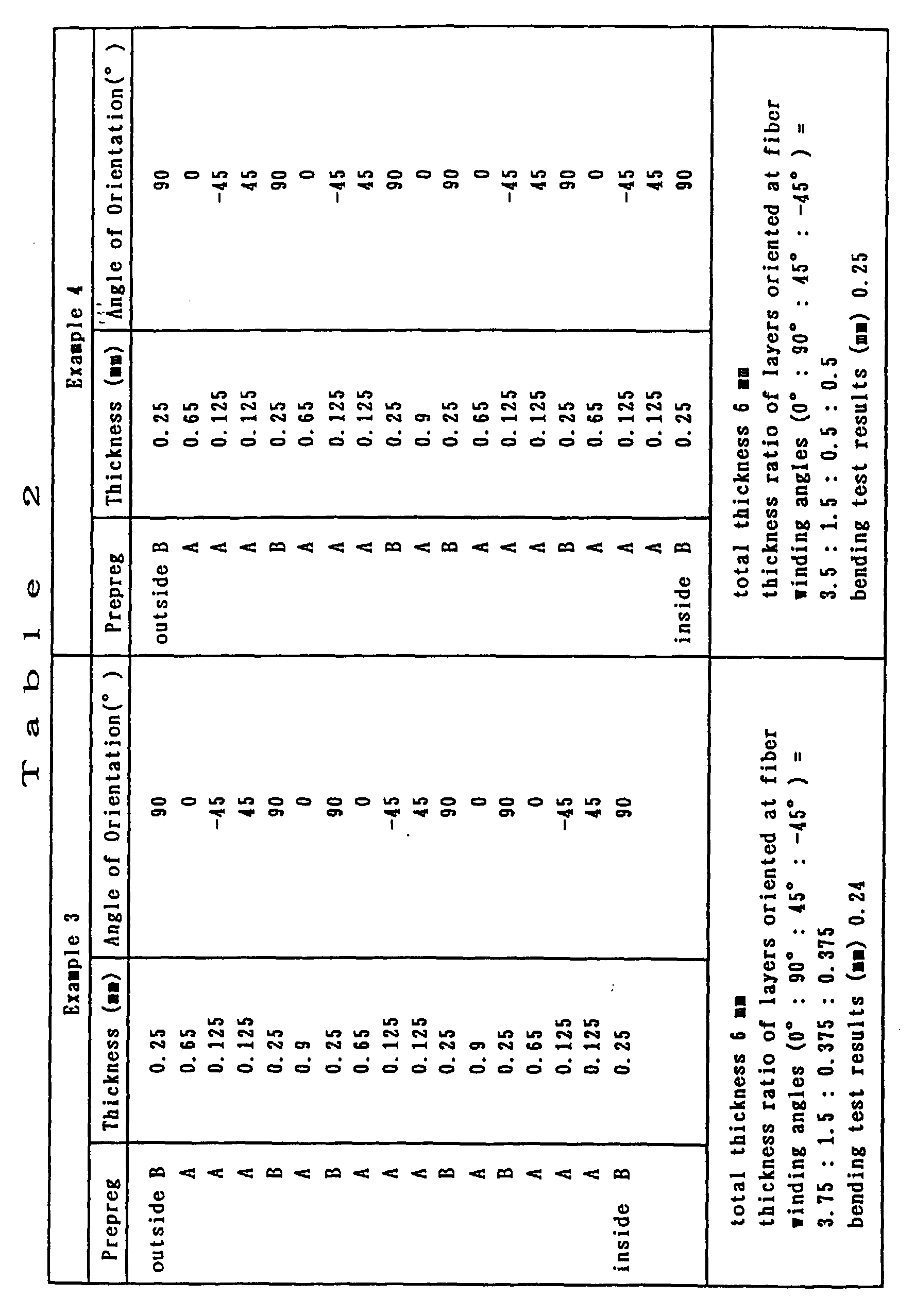
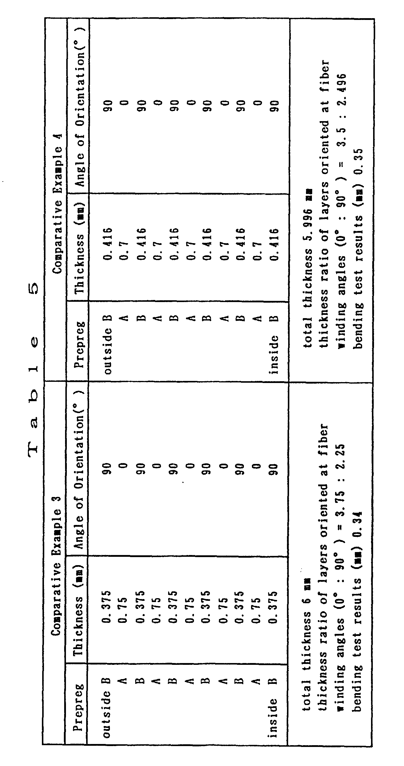
- The sheet prepregs A and B produced by impregnating carbon fibers arranged in one direction with an epoxy resin were wound up one layer by one layer around the mandrel of a three-roll wind-up machine in such a way as to constitute layers respectively oriented at four carbon fiber winding angles of 0°, 90°, 45° and -45° with the longer direction thereof, or at two carbon fiber winding angles of 0° and 90° with the longer direction thereof to laminate 11 to 19 layers differing in thickness and angle of orientation. Herein, the prepreg A was used for layers oriented at fiber winding angles of 0°, 45° and -45°, while the prepreg B was used for layers oriented at a fiber winding angle of 90°. The laminating patterns in Examples 1 to 6 and Comparative Examples 1 to 5 are summarized in Tables 1 to 6.
- After all prepreg sheets were wound up around the mandrel, they were taped using a stretched polypropylene resin tape (trade name: MIRAYPHANE, manufactured by Mitsubishi Rayon Co., Ltd.) in order to maintain the shape thereof, and then heat-cured in a heating oven under ordinary pressure at 130 °C for 1 hour, followed by removal of the polypropylene resin tape and the mandrel to produce a fiber-reinforced composite cylindrical form.
- The results of the bending test for cylindrical forms obtained in the foregoing manner are summarized in Tables 1 to 6, from which it will be understandable that fiber-reinforced composite cylindrical forms of Examples 1 to 6 wherein the layers thereof were respectively oriented at fiber winding angles of 90°, 0°, 45° and -45° with the longer direction thereof were decreased in deflection as compared with fiber-reinforced composite cylindrical forms of Comparative Examples 1 to 5 wherein the layers thereof were respectively oriented at fiber winding angles of 90° and 0° with the longer direction thereof.




- As described hereinbefore, the fiber-reinforced composite cylindrical form of the present invention is lightweight, high in rigidity, and little in deflection because the layers thereof are respectively oriented at four fiber winding angles of 0°, 90°, 40 to 50° and -40 to -50° with the longer direction thereof.
Claims (11)
- A cylindrical form made of a fiber-reinforced composite prepared by winding up unidirectional prepreg sheets around a mandrel and then heat-curing the thus wound sheets,
characterized in that the cylindrical form is untapered, the prepreg sheets are wound up around an untapered mandrel so that the reinforcing fibers of said sheets are oriented at four winding angles of 0°, 90°, 40° to 50° and -40° to -50° with respect to the longitudinal direction of said cylindrical form to be prepared and the sheets oriented at the four fiber winding angles respectively account for 50 to 90%, 5 to 35%, 2 to 20% and 2 to 20% of the total thickness of all said sheets. - The fiber-reinforced composite cylindrical form according to claim 1, wherein the reinforcing fiber for use in the unidirectional prepreg sheets to be oriented in the directions of 0°, 40° to 50° and -40° to -50° to the longitudinal direction has a tension modulus ranging from 400 to 900 GPa.
- The fiber-reinforced composite cylindrical form according to claim 1, wherein the reinforcing fiber for use in the unidirectional prepreg sheets to be oriented in the directions of 0°, 40° to 50° and -40° to -50° to the longitudinal direction has a compression strength ranging from 200 to 3,000 MPa.
- The fiber-reinforced composite cylindrical form according to claim 1, wherein the reinforcing fiber for use in the unidirectional prepreg sheets to be oriented in the directions of 0°, 40° to 50° and -40° to -50° to the longitudinal direction is pitch-based carbon fiber.
- The fiber-reinforced composite cylindrical form according to claim 1, wherein the reinforcing fiber for use in the unidirectional prepreg sheets to be oriented in the direction of 90° to the longitudinal direction has a compression strength ranging from 300 to 3,000 MPa.
- The fiber-reinforced composite cylindrical form according to claim 1, wherein the reinforcing fiber for use in the unidirectional prepreg sheets to be oriented in the direction of 90° to the longitudinal direction has a tensile modulus ranging from 50 to 900 GPa.
- The fiber-reinforced composite cylindrical form according to claim 1, wherein the reinforcing fiber for use in the unidirectional prepreg sheets to be oriented in the directions of 90° to the longitudinal direction is PAN-based carbon fiber.
- The fiber-reinforced composite cylindrical form according to claim 1, wherein the unidirectional prepreg sheets to be oriented in the directions of 40° to 50° and -40° to -50° to the longitudinal direction are disposed on upon another.
- The fiber-reinforced composite cylindrical form according to claim 1,
characterized in that a cloth-like prepreg sheet 0.5 to 1 mm in thickness is further superimposed over an outermost layer of the unidirectional prepreg sheet, a layer of said cloth-like prepreg sheet being subsequently decreased through cutting by a thickness of 0.2 to 0.9 mm. - The fiber-reinforced composite cylindrical form according to claim 1, wherein a cloth-like prepreg sheet is woven in form of a plain weave, satin weave or twill weave.
- Use of the untapered cylindrical form according to claim 1 as an industrial roller.
Applications Claiming Priority (3)
| Application Number | Priority Date | Filing Date | Title |
|---|---|---|---|
| JP145764/94 | 1994-06-06 | ||
| JP6145764A JPH07329199A (en) | 1994-06-06 | 1994-06-06 | Fiber-reinforced composite cylindrical molding |
| JP14576494 | 1994-06-06 |
Publications (3)
| Publication Number | Publication Date |
|---|---|
| EP0686482A2 EP0686482A2 (en) | 1995-12-13 |
| EP0686482A3 EP0686482A3 (en) | 1996-03-27 |
| EP0686482B1 true EP0686482B1 (en) | 2000-03-15 |
Family
ID=15392627
Family Applications (1)
| Application Number | Title | Priority Date | Filing Date |
|---|---|---|---|
| EP95108508A Expired - Lifetime EP0686482B1 (en) | 1994-06-06 | 1995-06-02 | Fiber reinforced composite article having cylindrical form |
Country Status (4)
| Country | Link |
|---|---|
| US (1) | US5753324A (en) |
| EP (1) | EP0686482B1 (en) |
| JP (1) | JPH07329199A (en) |
| DE (1) | DE69515556T2 (en) |
Families Citing this family (10)
| Publication number | Priority date | Publication date | Assignee | Title |
|---|---|---|---|---|
| EP0974379B1 (en) * | 1998-07-24 | 2006-06-14 | Daiwa Seiko Inc. | Sporting rod member using solid rod |
| WO2000039188A1 (en) | 1998-12-25 | 2000-07-06 | Mitsubishi Rayon Co., Ltd. | Epoxy resin composition, prepreg, and roll made of resin reinforced with reinforcing fibers |
| MY125417A (en) * | 1999-10-18 | 2006-07-31 | Stork Screens Bv | Thin-walled cylinder made from fibre-reinforced plastics material |
| KR20020077179A (en) | 2001-03-29 | 2002-10-11 | 니폰 미쓰비시 오일 코포레이션 | Robot hand member and method of producing the same |
| JP2002310135A (en) * | 2001-04-10 | 2002-10-23 | Nippon Oil Corp | Transfer roll base tube and transfer roll provided with the base tube |
| JP5013799B2 (en) * | 2006-09-27 | 2012-08-29 | 三菱重工印刷紙工機械株式会社 | Knife cylinder, rotary cutter, and knife mounting method |
| CN101532253B (en) * | 2008-03-12 | 2012-09-05 | 比亚迪股份有限公司 | Carbon fiber composite material product and manufacturing method thereof |
| JP5955539B2 (en) | 2010-12-03 | 2016-07-20 | イー・アイ・デュポン・ドウ・ヌムール・アンド・カンパニーE.I.Du Pont De Nemours And Company | Method for making cylinder-shaped elements for use in printing |
| US10241293B2 (en) | 2014-09-26 | 2019-03-26 | Massachusetts Institute Of Technology | Methods and apparatus for deployable sparse-aperture telescopes |
| DE202023102167U1 (en) * | 2023-04-24 | 2023-05-04 | Weber Fibertech Gmbh | structural component |
Family Cites Families (9)
| Publication number | Priority date | Publication date | Assignee | Title |
|---|---|---|---|---|
| DE2909393A1 (en) * | 1979-03-09 | 1981-03-12 | M.A.N. Maschinenfabrik Augsburg-Nürnberg AG, 8000 München | CYLINDRICAL HOLLOW BODY MADE OF FIBER COMPOSITE |
| US4248062A (en) * | 1979-10-05 | 1981-02-03 | Shakespeare Company | Drive shaft assembly and method for making same |
| US4463044A (en) * | 1981-09-28 | 1984-07-31 | The Boeing Company | Composite panel of varied thickness |
| JPS6349426A (en) * | 1986-08-18 | 1988-03-02 | Ryobi Ltd | Laminated pipe such as fishing rod |
| JP2707845B2 (en) * | 1991-01-23 | 1998-02-04 | 東レ株式会社 | Method for producing acrylonitrile-based graphitized fiber |
| JP3054623B2 (en) * | 1991-06-05 | 2000-06-19 | 株式会社シマノ | Rod material and method of manufacturing the same |
| US5156396A (en) * | 1991-08-26 | 1992-10-20 | Somar Corporation | Golf club shaft |
| JP2554821B2 (en) * | 1992-02-19 | 1996-11-20 | 新日本製鐵株式会社 | Carbon fiber reinforced resin composite material and method for producing the same |
| GB2276119A (en) * | 1993-03-18 | 1994-09-21 | Secr Defence | Hybrid composite materials |
-
1994
- 1994-06-06 JP JP6145764A patent/JPH07329199A/en active Pending
-
1995
- 1995-06-01 US US08/456,353 patent/US5753324A/en not_active Expired - Fee Related
- 1995-06-02 EP EP95108508A patent/EP0686482B1/en not_active Expired - Lifetime
- 1995-06-02 DE DE69515556T patent/DE69515556T2/en not_active Expired - Fee Related
Also Published As
| Publication number | Publication date |
|---|---|
| EP0686482A3 (en) | 1996-03-27 |
| EP0686482A2 (en) | 1995-12-13 |
| JPH07329199A (en) | 1995-12-19 |
| DE69515556D1 (en) | 2000-04-20 |
| DE69515556T2 (en) | 2000-07-20 |
| US5753324A (en) | 1998-05-19 |
Similar Documents
| Publication | Publication Date | Title |
|---|---|---|
| EP0733469B1 (en) | Composite structural member with high bending strength and method of manufacture | |
| USRE35081E (en) | Composite structural member with high bending strength | |
| US5188872A (en) | Composite structural member with high bending strength | |
| EP0541795B1 (en) | New prepreg and composite molding, and production of composite molding | |
| US4536438A (en) | Fibre reinforced composites | |
| EP0436391A2 (en) | Hybrid prepreg, manufacturing method therefor and articles incorporating such prepreg | |
| EP0637700A2 (en) | Carbon fiber reinforced resin coil spring and method for manufacturing the same | |
| US6893712B2 (en) | Transport member | |
| EP1240452B1 (en) | Thin-walled cylinder made from fibre-reinforced plastics material | |
| US5702993A (en) | Triaxial fabric composed of carbon fiber strands and method for production thereof | |
| US5552214A (en) | Unidirectional prepreg and carbon fiber reinforced composite materials comprising pitch-based carbon fibers and polyacrylonitrile-based carbon fibers | |
| US5753324A (en) | Fiber-reinforced composite cylindrical form | |
| US8852021B2 (en) | Golf club shaft and golf club using the same | |
| JP3317619B2 (en) | Hollow shaft with taper | |
| JP2005270515A (en) | Tubular body made of fiber reinforced composite material | |
| KR100298101B1 (en) | Fiber Reinforced Composite Material | |
| US5916682A (en) | Carbon fiber reinforced composite material | |
| JPS6143579B2 (en) | ||
| US20150182824A1 (en) | Shaft made of fiber-reinforced composite material | |
| JPH07144371A (en) | High damping carbon fiber reinforced resin composite material | |
| JPH10272699A (en) | Method for producing fiber reinforced resin tubular body | |
| JPH09277389A (en) | Hollow shaft with taper | |
| JP2005238517A (en) | Tubular laminate comprising non-woven fabric and method for producing the same | |
| JP4218105B2 (en) | How to adjust roll and dynamic balance | |
| JP2000263653A (en) | Tubular body made of fiber reinforced composite material |
Legal Events
| Date | Code | Title | Description |
|---|---|---|---|
| PUAI | Public reference made under article 153(3) epc to a published international application that has entered the european phase |
Free format text: ORIGINAL CODE: 0009012 |
|
| AK | Designated contracting states |
Kind code of ref document: A2 Designated state(s): DE FR |
|
| PUAL | Search report despatched |
Free format text: ORIGINAL CODE: 0009013 |
|
| AK | Designated contracting states |
Kind code of ref document: A3 Designated state(s): DE FR |
|
| 17P | Request for examination filed |
Effective date: 19960612 |
|
| 17Q | First examination report despatched |
Effective date: 19980130 |
|
| GRAG | Despatch of communication of intention to grant |
Free format text: ORIGINAL CODE: EPIDOS AGRA |
|
| GRAG | Despatch of communication of intention to grant |
Free format text: ORIGINAL CODE: EPIDOS AGRA |
|
| GRAH | Despatch of communication of intention to grant a patent |
Free format text: ORIGINAL CODE: EPIDOS IGRA |
|
| GRAH | Despatch of communication of intention to grant a patent |
Free format text: ORIGINAL CODE: EPIDOS IGRA |
|
| GRAA | (expected) grant |
Free format text: ORIGINAL CODE: 0009210 |
|
| AK | Designated contracting states |
Kind code of ref document: B1 Designated state(s): DE FR |
|
| PG25 | Lapsed in a contracting state [announced via postgrant information from national office to epo] |
Ref country code: FR Free format text: LAPSE BECAUSE OF FAILURE TO SUBMIT A TRANSLATION OF THE DESCRIPTION OR TO PAY THE FEE WITHIN THE PRESCRIBED TIME-LIMIT Effective date: 20000315 |
|
| RAP2 | Party data changed (patent owner data changed or rights of a patent transferred) |
Owner name: NIPPON MITSUBISHI OIL CORPORATION |
|
| REF | Corresponds to: |
Ref document number: 69515556 Country of ref document: DE Date of ref document: 20000420 |
|
| PGFP | Annual fee paid to national office [announced via postgrant information from national office to epo] |
Ref country code: DE Payment date: 20000605 Year of fee payment: 6 |
|
| EN | Fr: translation not filed | ||
| PLBE | No opposition filed within time limit |
Free format text: ORIGINAL CODE: 0009261 |
|
| STAA | Information on the status of an ep patent application or granted ep patent |
Free format text: STATUS: NO OPPOSITION FILED WITHIN TIME LIMIT |
|
| 26N | No opposition filed | ||
| PG25 | Lapsed in a contracting state [announced via postgrant information from national office to epo] |
Ref country code: DE Free format text: LAPSE BECAUSE OF NON-PAYMENT OF DUE FEES Effective date: 20020403 |