EP0686453B1 - Resistance welding method for steel metal plates and aluminum metal plates and material for resistance welding - Google Patents
Resistance welding method for steel metal plates and aluminum metal plates and material for resistance welding Download PDFInfo
- Publication number
- EP0686453B1 EP0686453B1 EP95900308A EP95900308A EP0686453B1 EP 0686453 B1 EP0686453 B1 EP 0686453B1 EP 95900308 A EP95900308 A EP 95900308A EP 95900308 A EP95900308 A EP 95900308A EP 0686453 B1 EP0686453 B1 EP 0686453B1
- Authority
- EP
- European Patent Office
- Prior art keywords
- aluminum
- sheet
- based metal
- steel sheet
- metal sheet
- Prior art date
- Legal status (The legal status is an assumption and is not a legal conclusion. Google has not performed a legal analysis and makes no representation as to the accuracy of the status listed.)
- Expired - Lifetime
Links
Images




Classifications
-
- B—PERFORMING OPERATIONS; TRANSPORTING
- B23—MACHINE TOOLS; METAL-WORKING NOT OTHERWISE PROVIDED FOR
- B23K—SOLDERING OR UNSOLDERING; WELDING; CLADDING OR PLATING BY SOLDERING OR WELDING; CUTTING BY APPLYING HEAT LOCALLY, e.g. FLAME CUTTING; WORKING BY LASER BEAM
- B23K11/00—Resistance welding; Severing by resistance heating
- B23K11/16—Resistance welding; Severing by resistance heating taking account of the properties of the material to be welded
- B23K11/20—Resistance welding; Severing by resistance heating taking account of the properties of the material to be welded of different metals
-
- B—PERFORMING OPERATIONS; TRANSPORTING
- B23—MACHINE TOOLS; METAL-WORKING NOT OTHERWISE PROVIDED FOR
- B23K—SOLDERING OR UNSOLDERING; WELDING; CLADDING OR PLATING BY SOLDERING OR WELDING; CUTTING BY APPLYING HEAT LOCALLY, e.g. FLAME CUTTING; WORKING BY LASER BEAM
- B23K11/00—Resistance welding; Severing by resistance heating
- B23K11/10—Spot welding; Stitch welding
- B23K11/11—Spot welding
- B23K11/115—Spot welding by means of two electrodes placed opposite one another on both sides of the welded parts
-
- B—PERFORMING OPERATIONS; TRANSPORTING
- B23—MACHINE TOOLS; METAL-WORKING NOT OTHERWISE PROVIDED FOR
- B23K—SOLDERING OR UNSOLDERING; WELDING; CLADDING OR PLATING BY SOLDERING OR WELDING; CUTTING BY APPLYING HEAT LOCALLY, e.g. FLAME CUTTING; WORKING BY LASER BEAM
- B23K2103/00—Materials to be soldered, welded or cut
- B23K2103/02—Iron or ferrous alloys
- B23K2103/04—Steel or steel alloys
-
- B—PERFORMING OPERATIONS; TRANSPORTING
- B23—MACHINE TOOLS; METAL-WORKING NOT OTHERWISE PROVIDED FOR
- B23K—SOLDERING OR UNSOLDERING; WELDING; CLADDING OR PLATING BY SOLDERING OR WELDING; CUTTING BY APPLYING HEAT LOCALLY, e.g. FLAME CUTTING; WORKING BY LASER BEAM
- B23K2103/00—Materials to be soldered, welded or cut
- B23K2103/18—Dissimilar materials
- B23K2103/20—Ferrous alloys and aluminium or alloys thereof
Definitions
- the present invention relates to a method for resistance welding dissimilar metal sheets such as steel-based metal sheets and aluminum-based metal sheets, which are used in assembling automobiles, railway vehicles, ships, building structures, etc., and a material used for said method, and more particularly to a method for resistance welding a steel-based metal sheet to an aluminum-based metal sheet, which method is suitable for spot welding between a steel-based metal sheet, which has been subjected to rust preventive treatment by plating, and an aluminum-based metal sheet, and an aluminum-clad steel sheet suitable for said method.
- This resistance welding is the same as the conventional resistance welding disclosed in the prior art documents and the like in that base metals to be welded are a steel sheet and an aluminum sheet. Therefore, a method is considered wherein an aluminum- clad steel sheet is inserted between the plated steel sheet and the aluminum-based metal sheet and, in this state, resistance welding is carried out.
- Japanese Unexamined Patent Publications (Kokai) No. 4-55066, No. 4-127973, and No. 4-253578 disclose spot welding between a steel-based metal sheet and an aluminum-based metal sheet using an aluminum-clad steel sheet as an insert material.
- These conventional methods suffer from problems such as the necessity of two-step energizations and the necessity of heavy currents.
- no consideration is given to a method for ensuring high joint strength in a wide range of current values and a method for spot welding between a plated steel sheet and an aluminum-based metal sheet. Further, in this method for joining dissimilar metals, modification of the electrode shape and the use of a projection are not taken into consideration.
- the conventional method for spot welding a steel-based metal sheet to an aluminum-based metal sheet using an aluminum-clad steel sheet as an insert material involves a troublesome step of changing the direction of current flow in a two-step energization.
- the plating on the plated steel sheet side hinders the formation of a nugget in a welding current range from about 8 to 11 kA, a high current.
- the welding current may be increased.
- the increase in current value poses problems including deposition of aluminum on the electrode on the aluminum-based metal sheet side and deposition of plating on the electrode on the plated steel sheet side to cause welding between the sheet and the electrode, shortened electrode tip life, and unstable current flow to cause variations in strength, resulting in lowered strength.
- An object of the present invention is to provide a method for resistance welding dissimilar metals, which method enables high joint strength to be ensured over a wide range of current values, minimizes the deposition of aluminum or plating on the electrode, and minimizes the lowering in fatigue strength of the joint.
- Another object of the present invention is to ensure a high current density in an early stage of the energization by reducing the area of abutment between the plated steel sheet and the aluminum-clad steel sheet in resistance welding with an aluminum-clad steel sheet interposed between the plated steel sheet and the aluminum-based metal sheet and thereby to provide a method for resistance welding a plated steel sheet to an aluminum-based metal sheet and a material for the resistance welding which can solve the above problems.
- the objects are solved by the features of claims 1, 2, 3, 9 and 10.
- a technical feature of the present invention is that, by virtue of a reduced area of abutment between a plated steel sheet and an aluminum-clad steel sheet, a high current density can be ensured in an early stage of energization when a current flows across a plated steel sheet and an aluminum-base metal sheet. Therefore, the temperature of the interface of the plated steel sheet and the aluminum-clad steel sheet can be efficiently raised, permitting a proper weld nugget to be formed on both sides of the aluminum-clad steel sheet.
- the current-carrying area can be reduced without any special working of the plated steel sheet and aluminum-clad steel sheet per se.
- an aluminum-clad steel sheet with irregularities, having a predetermined percentage area, formed on the surface of the steel-base metal is interposed between the plated steel sheet and the aluminum-base metal sheet, a proper current-carrying area is always ensured between the plated steel sheet and the aluminum-clad steel sheet, regardless of the site where the resistance welding is to be carried out.
- the sheet thickness ratio of the aluminum-clad steel sheet is important in order to effectively generate heat on the plated steel sheet side.
- the heat generated at that time is also transmitted to the aluminum-based metal side of the aluminum-clad steel sheet. If the sheet thickness ratio of the aluminum-based metal layer is higher than the above range, the cooling effect is increased and the heat generation effect on the steel-based metal sheet side is reduced, resulting in lowered joint strength. On the other hand, if the sheet thickness ratio of the steel-based metal sheet is higher than the above range, problems, including that of surface flash or expulsion, are likely to occur on the aluminum-based metal sheet side and the weight reduction effect of the sheet per se is reduced.
- a CF-type or P-type electrode In spot welding between a steel sheet or a plated steel sheet and an aluminum-based sheet using an insert material, a CF-type or P-type electrode, 2.0 to 5.0 mm in diameter at the front end, is disposed on the steel-based metal sheet side or the plated steel sheet side.
- a steel-based metal sheet or plated steel sheet with a projection having a diameter of 2.0 to 5.0 mm and a height of 0.6 to 1.5 mm may be used to focus the current flow on the steel-based metal sheet side or plated steel sheet side at the time of energization, thereby enhancing the amount of heat generated. This enables the formation and growth of a nugget on the steel-based metal sheet side or plated steel sheet side to be promoted in a low current region (7.5 to 11.0 kA).
- the heat generated at that time has an effect on the aluminum-based metal sheet side by heat conduction and, consequently, the formation and growth of a nugget on the aluminum side is promoted, improving the weld strength. Since failure in a tensile test occurs on the aluminum-based metal sheet side, the growth of the nugget on the aluminum side contributes to an improvement in joint strength.
- an aluminum-clad steel sheet which has an aluminum-based metal sheet to steel-based metal sheet thickness ratio of 1 : 1.3 to 1 : 5.0 and a thickness of 0.2 to 1.2 mm
- the use of an R-type or an F-type electrode of not less than 80 mm in radius of curvature of the curved face at the front end on the aluminum-based metal sheet side results in dispersion of the current flow, preventing surface flash or expulsion or the deformation of the aluminum-base metal sheet caused by excessive generation of heat. This ensures high joint strength.
- the thickness of the aluminum-clad steel sheet is limited to 0.2 to 1.2 mm is that if the sheet thickness is smaller than the above range, no nugget having satisfactory size can be formed, resulting in no improvement in strength or the formation of an intermetallic compound due to excessive heat input.
- the presence of the aluminum-clad steel sheet causes a difference in level between the steel-based metal sheet and the aluminum-based metal sheet to be welded, causing problems such as limitation of usable site, necessity of high current for providing high joint strength, or remarkably lowered fatigue strength of the joint.
- the thickness of the aluminum-clad steel sheet is preferably as small as possible. However, a certain thickness is necessary for sufficiently ensuring the amount of heat generated and for satisfactorily growing the nugget.
- the reason why the fatigue strength folls with increased thickness of the aluminum-clad steel sheet is thought to be as follows. Since the joint has a three-ply structure using an aluminum-clad steel sheet, the eccentricity of the load becomes large. This causes a bending moment acting on the vicinity of the nugget to become larger than that in the case of a two-ply structure, so that the stress increases with increasing the thickness of the insert material.
- the thickness of the aluminum-clad steel sheet is preferably as small as possible.
- the thickness of the aluminum-clad steel sheet is considered to be desirably 1.2 mm or less, which causes no fatigue strength problem in practical use, preferably 0.4 to 1.0 mm.
- the weld current is limited to 7.5 to 15.5 kA because, when it is lower than the above range, the joint strength is lowered, while when it exceeds the above range, surface splash or expulsion is likely to occur, or the amount of aluminum or plating on the electrode is increased.
- the weld time is limited to 80 to 280 ms. When it is less than the above range, the growth of a nugget is unsatisfactory, resulting in lowered strength. On the other hand, when it exceeds the above range, the improvement in strength is saturated. In practical use, the weld time is preferably 140 to 240 ms from the viewpoint of providing stable strength.
- the welding load may be determined according to the sheet thickness and 2.45 ⁇ t kN (wherein t represents the smallest sheet thickness among the thicknesses of the steel-based metal sheet, plated steel sheet, aluminum-clad steel sheet, and aluminum-based metal sheet) (for example, about 1.47 to 3.43 kN).
- the weld current flow becomes unstable, while, when it is higher than the above range, unfavorable phenomena occurs such as lowering in contact resistance to cause a reduced amount of heat generated or increase in deformation of a sheet, particularly an aluminum-based metal sheet, by contact with an electrode to cause a lowering in strength. For this reason, it is preferred to select the welding load according to the above criteria.
- the diameter of the contact face at the front end of the CF-type or P-type electrode on the steel-based metal sheet side or plated steel sheet side is limited to 2.0 to 5.0 mm.
- the reason for this is as follows. When it is less than the above range, unfavorable phenomena occur such as unstable current flow, welding of the electrode to the sheet by excessive generation of heat, and formation of an impression having an excessive depth by the electrode. On the other hand, when it is larger than the above range, the effect of improving the current density is deteriorated.
- the radius of curvature of the curved face at the front end of the R-type electrode on the aluminum-based metal sheet side is limited to not less than 80 mm because, when it is less than the above value, the effect of lowering the current density and thereby preventing the occurrence of surface splash or expulsion is lowered.
- the size of the projection is limited to 2.0 to 5.0 mm in diameter and 0.6 to 1.5 mm in height.
- unfavorable phenomena including that the current flow becomes unstable, the projection is collapsed, or the contact of the projection alone becomes difficult.
- the effect of improving the current density becomes small.
- the welding load may be properly selected in the range of about 0.68 to 4.41 kN according to the size of the projection.
- the thickness of the steel-based metal sheet, plated steel sheet, and aluminum-based metal sheet used in the present invention is preferably in the range of 0.5 to 2.0 mm from the viewpoint of maintaining high joint strength through effective utilization of the heat generation effect.
- the plating provided on the steel-based metal may be any plating (such as Zn, Zn-Fe, Zn-Al, or Zn-Ni) so far as it is conductive.
- the coverage (on double side basis) is preferably not more than 100/100 g/m 2 .
- the aluminum-clad steel sheet used in the welding method according to the present invention may be produced by any method so far as it is a metallurgical method, such as rolling, explosive cladding, HIP, or diffusion joining.
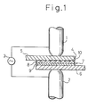
- Fig. 1 is a conceptual diagram illustrating a method for carrying out resistance welding between a steel sheet and an aluminum-based metallic sheet.
- an alternating-current power supply 3 is connected to electrodes 1 and 2.
- the alternating-current power supply 3 serves to supply the electrodes 1 and 2 with an alternating-current voltage of a predetermined period and a predetermined voltage for a predetermined duration under preset conditions.
- Both the electrodes 1 and 2 are dome radius type (DR type) electrodes of 6 mm in diameter and 40 mm in radius at the front face and displace together, with a not shown arm to create a predetermined load between both the electrodes.
- DR type dome radius type
- a welding member 4 abutted against the electrode 1 is a rust-prevention plated steel sheet 4 having on its both sides a plating 5 provided by galvanizing.
- the welding member 6 abutted against the electrode 2 is an aluminum sheet 6 formed of an aluminum-based metal.
- An aluminum-clad steel sheet 7 comprising a laminate of a steel layer 8 and an aluminum layer 9 is interposed between the plated steel sheet 4 and the aluminum sheet 6.
- the steel layer 8 and the aluminum layer 9 are laminated on top of the other by a solid phase joint such as pressure welding.
- Fig. 2 is a plan view (Fig. 2(A)) and a front sectional view (Fig. 2(B)) of an aluminum-clad steel sheet 7.
- the surface of the steel layer 8 has a plurality of protrusions 10 having a predetermined height and a predetermined percentage area at a predetermined pitch.
- the resistance welding used in the present example is a welding method in which a predetermined load is applied between metals to be welded and, in this state, an electric current is allowed to flow to generate heat by resistance heating at the interface between the metals, which heat is used as a heat source to form and grow a weld nugget at the interface region.
- the amount of heat generated by the resistance heating is equal to the power consumption across the electrodes 1, 2, and the amount of heat generated per unit volume is proportional to the scare of the current density. Therefore, in order to increase the amount of the temperature rise at the welding portion based on an identical power consumption, it is necessary to improve the current density at the time of resistance welding.
- the plating melts during the resistance welding, and, as described above, if no measure is taken against the melting of the plating, the weld area is increased, making it difficult to ensure a suitable current density.
- the protrusions 10 are provided in the aluminum-clad steel sheet 7 from the viewpoint of avoiding an adverse effect of the melting of the plating 5 on the welding. Specifically, as shown in Fig. 3, they are provided for forming a small current-carrying area between the plated steel sheet 4 and the aluminum-clad steel sheet 7.
- the current carrying area formed by a predetermined flow of current across the materials to be welded, i.e., the plated steel sheet 4, aluminum sheet 6, and the aluminum-clad steel sheet 7, by application of a predetermined alternating voltage across the electrodes 1, 2 is bounded by the area of the protrusion 10 in the aluminum-clad steel sheet 7.
- the resistance heating caused by the current flow is centralized in the abutted area between the protrusion 10 in the aluminum-clad steel sheet 7 and the plated steel sheet 4. Further, the plating 11 melted by the generated heat deposits on the surface of the aluminum-clad steel sheet 7 except for the protrusion 10. Therefore, there is no possibility that the abutted area between the plated steel sheet 4 and the aluminum-clad steel sheet 7, that is, the current-carrying area, is increased by the melted plating.
- resistance welding was carried out using a steel sheet, both sides of which have been galvanized at a coverage of 60/60g/m 2 , as the plated steel sheet 4, and A5052 (JIS standards) as the aluminum sheet 6 under conditions of a weld load between the electrodes of 1.96 kN and a weld time of 167 ms (corresponding to 10 cycles in a 60 Hz alternating-current power supply) with the shape of the protrusion 10 and the weld current value varied.
- Runs No. 1 to 3 and Runs No. 4 to 6 show comparison data for the resistance welding method of the present invention.
- welding was carried out using a steel sheet of the present example not having a plating 5 for Runs No. 1 to 3 and using a steel sheet having a plating 5 in combination with an aluminum-clad steel sheet 7 not having a protrusion 10 for Runs No. 4 to 6.
- Tables 2 to 4 show the results of experiments on resistance welding with the height of the protrusion 10, the percentage area of the protrusion 10 in the aluminum-clad steel sheet 7, and the pitch of the protrusion 10 being varied as a parameter. In all the cases, the provision of the protrusion 10 offered better results than the case where no protrusion was provided.
- the height of the protrusion may be not more than 0.05 mm with the height being preferably 0.02 to 1.0 mm, still preferably 0.05 to 0.5 mm.
- the protrusions are preferably provided at a pitch of not more than 3.0 mm by taking into consideration the relationship with the dimension of the electrodes 1, 2.
- the weldability of a steel sheet can be improved by providing projections in the material to be welded in the step of pressing for the purpose of focusing the current flow. If this technique is applied to the resistance welding of a plated steel sheet, the provision of a projection 15 in an aluminum-clad steel sheet 12 as shown in Fig. 4 is considered. In this case, however, welding should be carried out while catching the projection 15 in such a state that the aluminum-clad steel sheet 12 is sandwiched between the plated steel sheet 4 and the aluminum sheet 6, which deteriorates the workability.
- the current can be properly focused in the abutment of the electrodes 1, 2 in any region where the aluminum-clad steel sheet 4 exists, resulting in the realization of resistance welding having good workability.
- the prevention of an increase in a current-carrying path created between the plated steel sheet 4 and the aluminum-clad steel sheet 7 is realized by providing protrusions 10 on the aluminum-clad steel sheet 7.
- the present invention is not limited to this construction only, and any construction may be adopted so far as an increase in current-carrying area can be prevented.
- the provision of projections in the aluminum-clad steel sheet is convenient and cost-effective and, hence, advantageous.
- the aluminum-clad steel sheet 7 shown in Fig. 2 has protrusions 10 in a square pillar form.
- the function of the projections 10 is to reduce the contact area between the plated steel sheet 4 and the aluminum-clad steel sheet 7, and the shape of the protrusion is not particularly limited so far as the protrusion performs the above function.
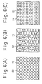
- the same effect can be attained using, for example, an aluminum-clad steel sheet 19 having cylindrical protrusions 20 as shown in Fig. 6 (A), an aluminum-clad steel sheet 21 having trigonal prismatic protrusions 22 as shown in Fig. 6 (B), or an aluminum-clad steel sheet 23 having square pillar recesses 24 as shown in Fig. 6 (C).
- the protrusions may be columnar or in such a form that the sectional area is reduced toward the front end.
- the recesses may be columnar or in such a form that the sectional area of the recess is reduced toward the bottom of the recess.
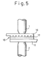
- Protrusions or recesses 10, 17, 20, 22, 24 may be formed in the aluminum-clad steel sheets 7, 19, 21, 23, the plated steel sheet 16, and the like may be formed by a method wherein a relief pattern is compression-formed on a steel layer of an aluminum-clad steel sheet or plated steel sheet having no relief pattern, for example, by a pressure roll or a method wherein a groove is formed by machining, etching, laser beam machining, or the like.
- a method as shown in Fig. 7 wherein a thin steel sheet 26 in a net form having an opening 27 is pressure-jointed to an aluminum-clad steel sheet 25 (or a plated steel sheet 4) having no relief pattern or wherein, prior to resistance welding, a thin steel sheet is interposed between the aluminum-clad steel sheet 25 and the plated steel sheet 4.
- this method there is no need of forming a relief in the aluminum-clad steel sheet 25 and the plated steel sheet 4, enabling the resistance welding in the present example to be very easily carried out.
- the resistance welding method of the present invention can be applied also to, for example, roll spot welding as shown in Fig. 8 wherein a pair of rolls 28 and 30 having corresponding plurality of projections 29 and 31 are used to carry out spot welding in a continuous manner, or seam welding wherein materials to be welded are sandwiched between a pair of rolls not having any protrusion.
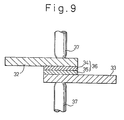
- Fig. 9 is a schematic cross-sectional view illustrating another embodiment of the present invention.
- spot welding was carried out using an a.c. welder under conditions (Nos. 31 to 34) specified in Table 5.
- the welding load was 1.96 kN, and the welding time was 200 ms (10 cycles).
- spot welding was carried out in the same manner as described above, except that conditions (Nos.
- the nugget diameter on the plated steel sheet side, the nugget diameter on the aluminum sheet side, the tensile shear strength, and the amounts of aluminum and plating deposited on the electrodes are given in Table 5. For all the runs, the failure in the tensile shear test occurred on the side of the aluminum sheet.
- the use of the aluminum-clad steel sheet A resulted in lowered current value, at which a nugget was formed on the plated steel sheet side, and the formation of a large nugget at a low current value on both the plated steel sheet side and the aluminum sheet side which in turn resulted in large tensile shear strength. That is, the use of the aluminum-clad steel sheet A provided higher joint strength at a wider range of current values than the use of the aluminum-clad steel sheet B.
- the joints thus obtained were evaluated for tensile shear fatigue properties with varied loads under a loading rate of 10 Hz and a stress ratio of 0.02, and an L-N curve was prepared based on the data.
- the results are given in Table 5 (Nos. 39 to 42).
- the use of the aluminum-clad steel sheet A resulted in lowered current value, at which a nugget was formed on the plated steel sheet side, and the formation of a large nugget at a low current value which in turn resulted in large tensile shear strength.
- the use of the aluminum-clad steel sheet A provided higher joint strength at a wider range of current values than the use of the aluminum-clad steel sheet B.
- the current value at which expulsion (causative of the dispersion of joint strength or lowering in strength) occurs on the aluminum sheet side was at least 4.0 kA higher than that in the case where the DR-type electrode was used on both the plated steel sheet side and the aluminum sheet side.
- a cold-rolled steel sheet 38 having a size of 30 x 60 x 0.80 mm was placed on a steel layer in an aluminum-clad steel sheet (an aluminum-clad steel sheet B) 42, having a size of 30 x 30 x 0.79 mm, a 0.39 mm-thick cold-rolled steel sheet 40 and a 0.40 mm-thick aluminum steel sheet 41 (A1050), and an aluminum sheet 39 (A5052) having a size of 30 x 60 x 1.00 mm was placed on an aluminum layer in the aluminum-clad steel sheet.
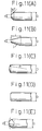
- spot welding was carried out using a CF-type electrode 43 of 3.6 mm in diameter of the contact face at the front end, d, (Fig.
- the nugget diameter, the tensile shear strength, and the amount of aluminum deposited on the steel layer side and the aluminum layer side at welding currents indicated are given in Table 6.
- the use of the CF-type electrode on the steel sheet with the R-type electrode used on the aluminum sheet side provided a larger nugget at a lower current (8.5 kA) and higher tensile shear strength.
- a combination of a CF-type electrode and an R-type electrode enables high joint strength to be provided in a wider range of current range as compared with a combination of a DR-type electrode and a DR-type electrode. Further, the combination of a DR-type electrode and a DR-type electrode needs high current (13.5 kA) for providing high strength, resulting in increased amount of aluminum deposited. By contrast, the combination of a CF-type electrode and an R-type electrode requires lower current for providing the same strength, enabling welding to be carried out in such a current range as will cause only a small amount of aluminum deposited.
- Example 4 a plated steel sheet (double side plated steel sheet, coverage: 60/60 g/m 2 ) was placed on a steel layer in the aluminum-clad steel sheet B, and an aluminum sheet (A5052) having a size of 30 x 60 x 1.00 mm was placed on an aluminum layer in the aluminum-clad steel sheet B.
- the welding load was 1.96 kN, and the welding time was 200 ms (10 cycles).
- the nugget diameter, the tensile shear strength, U-tension strength and the amount of aluminum and plating deposited on the steel layer side and the aluminum layer side at welding currents indicated are given in Table 6.
- the use of the CF-type electrode on the plated sheet side and the R-type or F-type electrode on the aluminum sheet side resulted in lowered current value for forming a nugget, the formation of a larger nugget at a lower current, and higher tensile shear strength for all the runs.
- a combination of a CF-type electrode and an R-type electrode and a combination of a CF-type electrode and an F-type electrode enabled high joint strength to be provided in a wider range of current range as compared with a combination of a DR-type electrode and a DR-type electrode.
- the combination of a DR-type electrode and a DR-type electrode needs high current for providing high joint strength, resulting in increased amount of aluminum and plating deposited.
- the combination of a CF-type electrode and an R-type electrode or a CF-type electrode and an F-type electrode needs lower current for providing the same strength, enabling welding to be carried out in such a current range as will cause only a small amount of aluminum and plating to be deposited.
- the current value at which expulsion occurs was 3.5 kA higher than that for the combination of a CF-type electrode and an R-type electrode, reducing the occurrence of expulsion.
- a steel sheet 38 having a size of 30 x 60 x 0.80 mm, provided with a projection 47 having a diameter 2.6 mm and a projection height of 0.8 mm was placed on a steel layer in an aluminum-clad steel sheet (an aluminum-clad steel sheet B) 42, having a size of 30 x 30 x 0.79 mm, of a 0.39 mm-thick cold-rolled steel sheet 40 and a 0.40 mm-thick aluminum steel sheet 41 (A1050), and an aluminum sheet 39 (A5052) having a size of 30 x 60 x 1.00 mm was placed on an aluminum layer in the aluminum-clad steel sheet.
- the welding load was 0.98 kN and the welding time was 140 ms (7 cycles).
- the results are given in Table 6 (Nos. 63 to 66).
- the use of the steel sheets having a projection resulted in lowered current value for forming a nugget, the formation of a larger nugget at a lower current and higher tensile shear strength for all the runs.
- the use of the steel sheets having a projection has enabled high joint strength to be provided in a wider range of current range as compared with the use of the steel sheets not having any projection. Further, the steel sheets not having any projection need high current for providing high joint strength, resulting in an increased amount of aluminum deposited. By contrast, the steel sheets having a projection need lower current for providing the same strength, enabling welding to be carried out in such a current range as will cause only a small amount of aluminum to be deposited.
- Example 6 a galvanized steel sheet, having a size of 30 x 60 x 0.80 mm, provided with a projection having a diameter 2.6 mm and a projection height of 0.8 mm was placed on a steel layer in the aluminum-clad steel sheet B, and an aluminum sheet (A5052) having a size of 30 x 60 x 1.00 mm was placed on an aluminum layer in the aluminum-clad steel sheet B.
- the welding load was 0.98 kN, and the welding time was 140 ms (7 cycles).
- the results are given in Table 6 (Nos. 67 to 70).
- the use of the plated steel sheets having a projection resulted in lowered current value for forming a nugget, the formation of a larger nugget at a lower current, and higher tensile shear strength for all the runs.
- the use of the plated steel sheets having a projection has enabled high joint strength to be provided in a wider range of current range as compared with the use of the plated steel sheets not having any projection.
- the plated steel sheets not having any projection need high currents for providing high joint strength, resulting in increased amount of aluminum and plating deposited.
- the steel sheets having a projection need lower current for providing the same strength, enabling welding to be carried out in such a current range as will cause only a small amount of aluminum and plating to be deposited.
- a current can be passed at a high density through between a steel-based metallic sheet or a plated steel sheet and an aluminum-clad steel sheet, enabling positions to be welded by resistance welding to be locally heated with high efficiency.
- This in turn enables a weld nugget to be suitably grown at a relatively low current, so that stable weld strength can be provided under relatively wide welding conditions.
- a suitable current-carrying area can be ensured between the plated steel sheet and the aluminum-clad steel sheet independent of the positions of the materials to be welded by resistance welding, enabling a contemplated effect to be attained without need of any high precision of the welding positions.
Landscapes
- Engineering & Computer Science (AREA)
- Mechanical Engineering (AREA)
- Resistance Welding (AREA)
Description
| Run No. | Aluminum-clad steel sheet | Steel sheet | Welding current (kA) | Tensile shear strength (kN) (average of n=2) | Classification | ||
| Height of protusion (mm) | Percentage area (%) | Pitch (mm) | |||||
| 1 | 0 (No projection) | - | - | No | 8 | 1.4 | Comp. Ex. |
| 2 | 0 | - | - | No | 11 | 2.8 | |
| 3 | 0 | - | - | No | 14 | 3.2 | |
| 4 | 0 (No projection) | - | - | Galvanized | 8 | 0 | |
| 5 | 0 | - | - | Galvanized | 11 | 1.7 | |
| 6 | 0 | - | - | Galvanized | 14 | 3.0 |
| Run No. | Aluminum-clad steel sheet | Steel sheet | Welding current (kA) | Tensile shear strength (kN) (average of n=2) | Classification | ||
| Height of protusion (mm) | Percentage area (%) | Pitch (mm) | |||||
| 7 | 0.04 | 50 | 1.0 | Galvanized | 8 | 0.7 | Ex. of inv. |
| 8 | 0.04 | 50 | 1.0 | Galvanized | 11 | 1.9 | |
| 9 | 0.04 | 50 | 1.0 | Galvanized | 14 | 2.8 | |
| 10 | 0.06 | 50 | 1.0 | Galvanized | 8 | 0.8 | |
| 11 | 0.06 | 50 | 1.0 | Galvanized | 11 | 2.5 | |
| 12 | 0.06 | 50 | 1.0 | Galvanized | 14 | 3.0 | |
| 13 | 0.1 | 50 | 1.0 | Galvanized | 8 | 1.4 | |
| 14 | 0.1 | 50 | 1.0 | Galvanized | 11 | 2.7 | |
| 15 | 0.1 | 50 | 1.0 | Galvanized | 14 | 3.2 |
| Run No. | Aluminum-clad steel sheet | Steel sheet | Welding current (kA) | Tensile shear strength (kN) (average of n=2) | Classification | ||
| Height of protusion (mm) | Percentage area (%) | Pitch (mm) | |||||
| 16 | 0.1 | 20 | 1.0 | Galvanized | 8 | 1.3 | Ex. of inv. |
| 17 | 0.1 | 20 | 1.0 | Galvanized | 11 | 2.9 | |
| 18 | 0.1 | 20 | 1.0 | Galvanized | 14 | 3.5 | |
| 13 | 0.1 | 50 | 1.0 | Galvanized | 8 | 1.4 | |
| 14 | 0.1 | 50 | 1.0 | Galvanized | 11 | 2.7 | |
| 15 | 0.1 | 50 | 1.0 | Galvanized | 14 | 3.2 | |
| 19 | 0.1 | 85 | 1.0 | Galvanized | 8 | 1.3 | |
| 20 | 0.1 | 85 | 1.0 | Galvanized | 11 | 2.7 | |
| 21 | 0.1 | 85 | 1.0 | Galvanized | 14 | 3.1 |
| Run No. | Aluminum-clad steel sheet | Steel sheet | Welding current (kA) | Tensile shear strength (kN) (average of n=2) | Classification | ||
| Height of protusion (mm) | Percentage area (%) | Pitch (mm) | |||||
| 22 | 0.1 | 50 | 0.7 | Galvanized | 8 | 1.3 | Ex. of inv. |
| 23 | 0.1 | 50 | 0.7 | Galvanized | 11 | 2.7 | |
| 24 | 0.1 | 50 | 0.7 | Galvanized | 14 | 2.9 | |
| 13 | 0.1 | 50 | 1.0 | Galvanized | 8 | 1.4 | |
| 14 | 0.1 | 50 | 1.0 | Galvanized | 11 | 2.7 | |
| 15 | 0.1 | 50 | 1.0 | Galvanized | 14 | 3.2 | |
| 25 | 0.1 | 50 | 2.0 | Galvanized | 8 | 1.4 | |
| 26 | 0.1 | 50 | 2.0 | Galvanized | 11 | 2.8 | |
| 27 | 0.1 | 50 | 2.0 | Galvanized | 14 | 3.3 | |
| 28 | 0.1 | 50 | 3.0 | Galvanized | 8 | 1.3 | |
| 29 | 0.1 | 50 | 3.0 | Galvanized | 11 | (2.7)(1.9) | |
| 30 | 0.1 | 50 | 3.0 | Galvanized | 14 | 3.2 |


- 1, 2, 37, 45, 46
- electrode
- 3
- alternating current power supply
- 4
- welding member to be welded
- 5
- plating
- 6, 33, 39
- aluminum-base metal sheet
- 7, 12, 18, 19, 21
- aluminum-clad steel sheet
- 23, 25, 36, 42
- aluminum-clad steel sheet
- 8, 13, 34, 40
- steel layer
- 9, 14, 35, 41
- aluminum layer
- 10, 17, 20, 22
- protrusion
- 11
- melted plating
- 15, 47
- projection
- 16, 32
- plated steel sheet
- 24
- recess
- 26
- thin steel sheet
- 27
- opening
- 28, 30
- roller
- 29, 31
- projection
- 38
- cold-rolled steel sheet
- 43
- electrode having small contact area
- 44
- electrode having large contact area
Claims (11)
- Method for resistance welding a plated steel sheet to an aluminium-based metal sheet, comprising the steps of: inserting an aluminium-clad steel sheet (7) comprising a laminate of a steel-based metal sheet (8) and an aluminium based metal sheet (9) between the plated steel sheet (4) and the aluminium-based metal sheet (6) so that the same types of metals face each other; and subjecting the resultant assembly to resistance welding, wherein protrusions (10; 17; 20; 22) are formed on at least one of the plated steel sheet (4) on the surface to be abutted against the aluminum-clad steel sheet (7) and the aluminum-clad steel sheet (7) on the surface to be abutted against the plated steel sheet (4), thereby reducing the current-carrying area.
- Method for resistance welding a plated steel sheet or a steel-based metal sheet to an aluminum-based metal sheet, comprising the steps of: inserting an aluminum-clad steel sheet (25) comprising a laminate of a steel-based metal sheet and an aluminum-based metal sheet between the plated steel sheet or the steel-based metal sheet and an aluminum-based metal sheet so that the same types of metals face each other; and subjecting the resultant assembly to resistance welding, wherein a steel-based metal sheet (26) having an opening (27) is interposed between the plated steel sheet or the steel-based metal sheet and the aluminum-clad steel sheet (25) to reduce the current-carrying area.
- Method for resistance welding the dissimilar metals of a steel-based metal sheet or a plated steel sheet and an aluminum-based metal sheet, comprising the steps of: inserting a 0.2 to 1.2 mm-thick aluminum-clad steel sheet (42) of a steel-based metal sheet (40) and an aluminum-based metal sheet (41) between a steel-based metal sheet (38) or a plated steel sheet and an aluminum-based metal sheet (39) so that the same types of metals face each other; and spot-welding the steel-based metal sheet or plated steel sheet to the aluminum-based metal sheet by single energization wherein the steel-based metal sheet (38) or plated steel sheet has a projection (47) with a diameter of 2.0 to 5.0 mm and a height of 0.6 to 1.5 mm and the welding is carried out under conditions of a weld current of 7.5 to 15.5 kA and a weld time of 80 to 2280 ms.
- Method according to claim 3, characterized in that a Radius-type electrode or a Flat-type electrode of not less than 80 mm radius of curvature of the front end is disposed on the side of the aluminum-based metal sheet.
- Method according to any of claims 1 to 4, characterized in that the aluminum-clad steel sheet has a thickness ratio of the aluminum-based metal sheet to the steel-based metal sheet in the range of from 1 : 1.3 to 1 : 5.0 and has a thickness of 0.2 to 1.2 mm.
- Method according to claim 1 or 5, wherein the protusions (10; 17; 20; 22) have a percentage area of 10 to 90% and a height of 0.02 to 1.0 mm.
- Method according to claims 1, 5 or 6, wherein the protrusions (10; 17; 20; 22) are in the form of a circular cylinder, a triangular prism, or a prism and provided at a pitch of not more than 3 mm.
- Method according to any of claims 1, 5 to 7, wherein the protrusions (10; 17; 20; 22) are formed by compression molding, machining, etching, or laser beam machining.
- A method for resistance welding the dissimilar metals of a plated steel sheet and an aluminum-based metal sheet, comprising the steps of: inserting a 0.2 to 1.2 mm-thick aluminum-clad steel sheet of a steel-based metal sheet and an aluminum-base metal sheet between a plated steel sheet and an aluminum-based metal sheet so that the same types of metals face each other; and spot-welding the plated steel sheet to the aluminum-based metal sheet by single energization, wherein the aluminum-clad steel sheet has a sheet thickness ratio of the aluminum-based metal sheet to the steel-based metal sheet in the range of from 1 : 1.3 to 1 : 5.0 and the welding is carried out under conditions of a weld current of 7.5 to 15.5 kA and a weld time of 80 to 280 ms.
- A method for resistance welding the dissimilar metals of a steel-based metal sheet or a plated steel sheet and an aluminum-base metal sheet, comprising the steps of: inserting a 0.2 to 1.2 mm-thick aluminum-clad steel sheet of a steel-based metal sheet and an aluminum-based metal sheet between a steel-based metal sheet or a plated steel sheet and an aluminum-based metal sheet so that the same types of metals face each other; and spot-welding the steel-based metal sheet or plated steel sheet to the aluminum-based metal sheet by a single energization, wherein a Cone Flat-type or Point-type electrode of 2.0 to 5.0 mm in contact area diameter of the front end is disposed on the side of the steel-based metal sheet or plated steel sheet with an Radius-type electrode or an Flat-type electrode of not less than 80 mm in radius of curvature of the front end being disposed on the side of the aluminum-based metal sheet and the welding is carried out under conditions of a weld current of 7.5 to 15.5 kA and a weld time of 80 to 280 ms.
- Method according to claim 10, characterized in that the aluminum-clad steel sheet has a thickness ratio of the aluminum-based metal sheet to the steel-based metal sheet in the range of from 1 : 1.3 to 1 : 5.0.
Applications Claiming Priority (7)
| Application Number | Priority Date | Filing Date | Title |
|---|---|---|---|
| JP307036/93 | 1993-11-15 | ||
| JP05307036A JP3117053B2 (en) | 1993-11-15 | 1993-11-15 | Resistance welding method and material for dissimilar metals |
| JP30703693 | 1993-11-15 | ||
| JP73468/94 | 1994-04-12 | ||
| JP06073468A JP3126587B2 (en) | 1994-04-12 | 1994-04-12 | Resistance welding method between plated steel and aluminum material and clad material |
| JP7346894 | 1994-04-12 | ||
| PCT/JP1994/001933 WO1995013898A1 (en) | 1993-11-15 | 1994-11-15 | Resistance welding method for steel metal plates and aluminum metal plates and material for resistance welding |
Publications (3)
| Publication Number | Publication Date |
|---|---|
| EP0686453A1 EP0686453A1 (en) | 1995-12-13 |
| EP0686453A4 EP0686453A4 (en) | 1996-02-14 |
| EP0686453B1 true EP0686453B1 (en) | 1999-07-14 |
Family
ID=26414615
Family Applications (1)
| Application Number | Title | Priority Date | Filing Date |
|---|---|---|---|
| EP95900308A Expired - Lifetime EP0686453B1 (en) | 1993-11-15 | 1994-11-15 | Resistance welding method for steel metal plates and aluminum metal plates and material for resistance welding |
Country Status (4)
| Country | Link |
|---|---|
| EP (1) | EP0686453B1 (en) |
| KR (1) | KR0171162B1 (en) |
| DE (1) | DE69419501T2 (en) |
| WO (1) | WO1995013898A1 (en) |
Families Citing this family (9)
| Publication number | Priority date | Publication date | Assignee | Title |
|---|---|---|---|---|
| KR100548015B1 (en) * | 1999-01-25 | 2006-02-01 | 삼성테크윈 주식회사 | Electric resistance welding electrode member |
| KR20010068100A (en) * | 2001-04-23 | 2001-07-13 | 부윤정 | Copper pipes and their winding to raise a cooling efficiency of the kimchi refrigerator |
| JP5376391B2 (en) * | 2007-03-30 | 2013-12-25 | 日産自動車株式会社 | Dissimilar metal joining method and joining structure |
| US8541110B2 (en) | 2011-01-19 | 2013-09-24 | GM Global Technology Operations LLC | Resistance spot welding manufacture and method of forming same |
| DE102012214163A1 (en) * | 2012-08-09 | 2014-02-13 | Siemens Aktiengesellschaft | Method for manufacturing lightweight rail vehicle, involves connecting light metal layer applied on to-be-joined ferrous portion, with iron-containing metal layer deposited on light metal joining portion by thermal joining process |
| KR101436112B1 (en) * | 2012-10-19 | 2014-09-01 | 희성금속 주식회사 | Electricity resistance welding method and apparatus for electrical contact point and hard solder of strip type |
| DE102014114335B4 (en) | 2013-10-04 | 2023-05-04 | GM Global Technology Operations LLC (n. d. Ges. d. Staates Delaware) | ALUMINUM ALLOY TO STEEL WELDING PROCESS |
| US20150352659A1 (en) | 2014-06-10 | 2015-12-10 | GM Global Technology Operations LLC | Cover plate with intruding feature to improve al-steel spot welding |
| KR102822369B1 (en) | 2020-07-17 | 2025-06-19 | 삼성디스플레이 주식회사 | Mask and manufacturing method of the same |
Family Cites Families (5)
| Publication number | Priority date | Publication date | Assignee | Title |
|---|---|---|---|---|
| DE740695C (en) * | 1937-04-23 | 1943-10-27 | Siemens Ag | Process for joining copper and light metal parts by electrical resistance butt or flash welding |
| FR2162317A1 (en) * | 1971-12-06 | 1973-07-20 | Bennes Marrel | Composite sheet with lightweight material - esp for vehicle bodies containers and material handling skips |
| JP2672182B2 (en) * | 1990-07-19 | 1997-11-05 | 株式会社神戸製鋼所 | Joining method for steel-based materials and aluminum-based materials |
| CA2069386A1 (en) * | 1991-06-25 | 1992-12-26 | Donald A. Rhoda | Counterweight attachment technique |
| JP2531052B2 (en) * | 1991-10-22 | 1996-09-04 | 住友金属工業株式会社 | Resistance welding method for dissimilar metals |
-
1994
- 1994-11-15 DE DE69419501T patent/DE69419501T2/en not_active Expired - Fee Related
- 1994-11-15 KR KR1019950702909A patent/KR0171162B1/en not_active Expired - Fee Related
- 1994-11-15 EP EP95900308A patent/EP0686453B1/en not_active Expired - Lifetime
- 1994-11-15 WO PCT/JP1994/001933 patent/WO1995013898A1/en not_active Ceased
Also Published As
| Publication number | Publication date |
|---|---|
| EP0686453A4 (en) | 1996-02-14 |
| DE69419501T2 (en) | 1999-11-18 |
| DE69419501D1 (en) | 1999-08-19 |
| KR960700124A (en) | 1996-01-19 |
| KR0171162B1 (en) | 1999-02-18 |
| WO1995013898A1 (en) | 1995-05-26 |
| EP0686453A1 (en) | 1995-12-13 |
Similar Documents
| Publication | Publication Date | Title |
|---|---|---|
| US5783794A (en) | Method and material for resistance welding steel-base metal sheet to aluminum-base metal sheet | |
| US5302797A (en) | Resistance welding of aluminum | |
| CN107160022A (en) | For aluminium workpiece and steel workpiece resistance spot welding match somebody with somebody composite electrode | |
| KR102057893B1 (en) | Spot welding method | |
| US5015816A (en) | Resistance welding electrode and process | |
| WO2017104647A1 (en) | Resistance spot welding method and method for manufacturing welded member | |
| JP2017047476A (en) | Spot welding method | |
| JP2017047475A (en) | Spot welding method | |
| US4954687A (en) | Resistance welding electrode and process | |
| EP0686453A1 (en) | Resistance welding method for steel metal plates and aluminum metal plates and material for resistance welding | |
| JP2020011253A (en) | Resistance spot welding method | |
| CN119855670A (en) | Welded member and method for manufacturing same | |
| CN114101883A (en) | Resistance spot welding method for low-melting-point coating steel workpiece | |
| JP4884958B2 (en) | Lap resistance spot welding method | |
| JP2024040644A (en) | Method for manufacturing resistance spot welded joints and method for manufacturing automobile parts | |
| JP3126587B2 (en) | Resistance welding method between plated steel and aluminum material and clad material | |
| US11772186B2 (en) | Spot welding method | |
| JPH04246182A (en) | Surface-treated steel sheet excellent in lap resistance weldability | |
| JP3117053B2 (en) | Resistance welding method and material for dissimilar metals | |
| KR20220047647A (en) | Resistance spot welding method, and method of manufacturing resistance spot welding seam | |
| JP7730078B2 (en) | Spot-welded member and method for manufacturing spot-welded member | |
| JP7586993B1 (en) | Method for manufacturing metal joint | |
| WO2021070836A1 (en) | Resistance spot welding method and method for manufacturing welded member | |
| JPH089104B2 (en) | Resistance welding method for steel sheet | |
| KR102948515B1 (en) | Resistance spot welding method |
Legal Events
| Date | Code | Title | Description |
|---|---|---|---|
| PUAI | Public reference made under article 153(3) epc to a published international application that has entered the european phase |
Free format text: ORIGINAL CODE: 0009012 |
|
| 17P | Request for examination filed |
Effective date: 19950721 |
|
| AK | Designated contracting states |
Kind code of ref document: A1 Designated state(s): DE FR GB |
|
| A4 | Supplementary search report drawn up and despatched | ||
| AK | Designated contracting states |
Kind code of ref document: A4 Designated state(s): DE FR GB |
|
| 17Q | First examination report despatched |
Effective date: 19970214 |
|
| GRAG | Despatch of communication of intention to grant |
Free format text: ORIGINAL CODE: EPIDOS AGRA |
|
| GRAG | Despatch of communication of intention to grant |
Free format text: ORIGINAL CODE: EPIDOS AGRA |
|
| GRAH | Despatch of communication of intention to grant a patent |
Free format text: ORIGINAL CODE: EPIDOS IGRA |
|
| GRAH | Despatch of communication of intention to grant a patent |
Free format text: ORIGINAL CODE: EPIDOS IGRA |
|
| GRAA | (expected) grant |
Free format text: ORIGINAL CODE: 0009210 |
|
| AK | Designated contracting states |
Kind code of ref document: B1 Designated state(s): DE FR GB |
|
| REF | Corresponds to: |
Ref document number: 69419501 Country of ref document: DE Date of ref document: 19990819 |
|
| ET | Fr: translation filed | ||
| RAP2 | Party data changed (patent owner data changed or rights of a patent transferred) |
Owner name: TOYOTA JIDOSHA KABUSHIKI KAISHA Owner name: NIPPON STEEL CORPORATION |
|
| PLBE | No opposition filed within time limit |
Free format text: ORIGINAL CODE: 0009261 |
|
| STAA | Information on the status of an ep patent application or granted ep patent |
Free format text: STATUS: NO OPPOSITION FILED WITHIN TIME LIMIT |
|
| 26N | No opposition filed | ||
| REG | Reference to a national code |
Ref country code: FR Ref legal event code: TP |
|
| PGFP | Annual fee paid to national office [announced via postgrant information from national office to epo] |
Ref country code: FR Payment date: 20011113 Year of fee payment: 8 |
|
| PGFP | Annual fee paid to national office [announced via postgrant information from national office to epo] |
Ref country code: GB Payment date: 20011114 Year of fee payment: 8 |
|
| PGFP | Annual fee paid to national office [announced via postgrant information from national office to epo] |
Ref country code: DE Payment date: 20011203 Year of fee payment: 8 |
|
| REG | Reference to a national code |
Ref country code: GB Ref legal event code: IF02 |
|
| PG25 | Lapsed in a contracting state [announced via postgrant information from national office to epo] |
Ref country code: GB Free format text: LAPSE BECAUSE OF NON-PAYMENT OF DUE FEES Effective date: 20021115 |
|
| PG25 | Lapsed in a contracting state [announced via postgrant information from national office to epo] |
Ref country code: DE Free format text: LAPSE BECAUSE OF NON-PAYMENT OF DUE FEES Effective date: 20030603 |
|
| GBPC | Gb: european patent ceased through non-payment of renewal fee | ||
| PG25 | Lapsed in a contracting state [announced via postgrant information from national office to epo] |
Ref country code: FR Free format text: LAPSE BECAUSE OF NON-PAYMENT OF DUE FEES Effective date: 20030731 |
|
| REG | Reference to a national code |
Ref country code: FR Ref legal event code: ST |