EP0686241B1 - Sicherheitsventil für drückgefässe - Google Patents
Sicherheitsventil für drückgefässe Download PDFInfo
- Publication number
- EP0686241B1 EP0686241B1 EP19940908663 EP94908663A EP0686241B1 EP 0686241 B1 EP0686241 B1 EP 0686241B1 EP 19940908663 EP19940908663 EP 19940908663 EP 94908663 A EP94908663 A EP 94908663A EP 0686241 B1 EP0686241 B1 EP 0686241B1
- Authority
- EP
- European Patent Office
- Prior art keywords
- fluid
- main valve
- valve member
- fluid pressure
- pressure
- Prior art date
- Legal status (The legal status is an assumption and is not a legal conclusion. Google has not performed a legal analysis and makes no representation as to the accuracy of the status listed.)
- Expired - Lifetime
Links
- 239000012530 fluid Substances 0.000 claims abstract description 142
- 238000004891 communication Methods 0.000 claims abstract description 11
- 230000035945 sensitivity Effects 0.000 claims description 6
- 238000011144 upstream manufacturing Methods 0.000 claims description 6
- 239000000463 material Substances 0.000 claims description 3
- 238000007789 sealing Methods 0.000 claims description 2
- 238000011068 loading method Methods 0.000 description 4
- 239000007788 liquid Substances 0.000 description 3
- 230000006978 adaptation Effects 0.000 description 2
- 238000013459 approach Methods 0.000 description 2
- 230000005484 gravity Effects 0.000 description 2
- 238000012986 modification Methods 0.000 description 2
- 230000004048 modification Effects 0.000 description 2
- 239000004677 Nylon Substances 0.000 description 1
- 239000004809 Teflon Substances 0.000 description 1
- 229920006362 Teflon® Polymers 0.000 description 1
- 238000009825 accumulation Methods 0.000 description 1
- 230000033228 biological regulation Effects 0.000 description 1
- 238000005336 cracking Methods 0.000 description 1
- 230000007423 decrease Effects 0.000 description 1
- 238000013461 design Methods 0.000 description 1
- 230000000694 effects Effects 0.000 description 1
- 239000012634 fragment Substances 0.000 description 1
- 239000000446 fuel Substances 0.000 description 1
- 239000002828 fuel tank Substances 0.000 description 1
- 230000000977 initiatory effect Effects 0.000 description 1
- 229920001778 nylon Polymers 0.000 description 1
- 230000002093 peripheral effect Effects 0.000 description 1
- 229920000915 polyvinyl chloride Polymers 0.000 description 1
- 239000004800 polyvinyl chloride Substances 0.000 description 1
- 230000000284 resting effect Effects 0.000 description 1
- 238000004513 sizing Methods 0.000 description 1
- 238000012546 transfer Methods 0.000 description 1
Images

Classifications
-
- F—MECHANICAL ENGINEERING; LIGHTING; HEATING; WEAPONS; BLASTING
- F16—ENGINEERING ELEMENTS AND UNITS; GENERAL MEASURES FOR PRODUCING AND MAINTAINING EFFECTIVE FUNCTIONING OF MACHINES OR INSTALLATIONS; THERMAL INSULATION IN GENERAL
- F16K—VALVES; TAPS; COCKS; ACTUATING-FLOATS; DEVICES FOR VENTING OR AERATING
- F16K17/00—Safety valves; Equalising valves, e.g. pressure relief valves
- F16K17/02—Safety valves; Equalising valves, e.g. pressure relief valves opening on surplus pressure on one side; closing on insufficient pressure on one side
- F16K17/04—Safety valves; Equalising valves, e.g. pressure relief valves opening on surplus pressure on one side; closing on insufficient pressure on one side spring-loaded
- F16K17/10—Safety valves; Equalising valves, e.g. pressure relief valves opening on surplus pressure on one side; closing on insufficient pressure on one side spring-loaded with auxiliary valve for fluid operation of the main valve
-
- F—MECHANICAL ENGINEERING; LIGHTING; HEATING; WEAPONS; BLASTING
- F16—ENGINEERING ELEMENTS AND UNITS; GENERAL MEASURES FOR PRODUCING AND MAINTAINING EFFECTIVE FUNCTIONING OF MACHINES OR INSTALLATIONS; THERMAL INSULATION IN GENERAL
- F16K—VALVES; TAPS; COCKS; ACTUATING-FLOATS; DEVICES FOR VENTING OR AERATING
- F16K17/00—Safety valves; Equalising valves, e.g. pressure relief valves
- F16K17/02—Safety valves; Equalising valves, e.g. pressure relief valves opening on surplus pressure on one side; closing on insufficient pressure on one side
- F16K17/12—Safety valves; Equalising valves, e.g. pressure relief valves opening on surplus pressure on one side; closing on insufficient pressure on one side weight-loaded
-
- F—MECHANICAL ENGINEERING; LIGHTING; HEATING; WEAPONS; BLASTING
- F16—ENGINEERING ELEMENTS AND UNITS; GENERAL MEASURES FOR PRODUCING AND MAINTAINING EFFECTIVE FUNCTIONING OF MACHINES OR INSTALLATIONS; THERMAL INSULATION IN GENERAL
- F16K—VALVES; TAPS; COCKS; ACTUATING-FLOATS; DEVICES FOR VENTING OR AERATING
- F16K17/00—Safety valves; Equalising valves, e.g. pressure relief valves
- F16K17/18—Safety valves; Equalising valves, e.g. pressure relief valves opening on surplus pressure on either side
- F16K17/19—Equalising valves predominantly for tanks
- F16K17/194—Equalising valves predominantly for tanks weight-loaded
-
- F—MECHANICAL ENGINEERING; LIGHTING; HEATING; WEAPONS; BLASTING
- F16—ENGINEERING ELEMENTS AND UNITS; GENERAL MEASURES FOR PRODUCING AND MAINTAINING EFFECTIVE FUNCTIONING OF MACHINES OR INSTALLATIONS; THERMAL INSULATION IN GENERAL
- F16K—VALVES; TAPS; COCKS; ACTUATING-FLOATS; DEVICES FOR VENTING OR AERATING
- F16K17/00—Safety valves; Equalising valves, e.g. pressure relief valves
- F16K17/18—Safety valves; Equalising valves, e.g. pressure relief valves opening on surplus pressure on either side
- F16K17/19—Equalising valves predominantly for tanks
- F16K17/196—Equalising valves predominantly for tanks spring-loaded
-
- Y—GENERAL TAGGING OF NEW TECHNOLOGICAL DEVELOPMENTS; GENERAL TAGGING OF CROSS-SECTIONAL TECHNOLOGIES SPANNING OVER SEVERAL SECTIONS OF THE IPC; TECHNICAL SUBJECTS COVERED BY FORMER USPC CROSS-REFERENCE ART COLLECTIONS [XRACs] AND DIGESTS
- Y10—TECHNICAL SUBJECTS COVERED BY FORMER USPC
- Y10T—TECHNICAL SUBJECTS COVERED BY FORMER US CLASSIFICATION
- Y10T137/00—Fluid handling
- Y10T137/0318—Processes
- Y10T137/0396—Involving pressure control
-
- Y—GENERAL TAGGING OF NEW TECHNOLOGICAL DEVELOPMENTS; GENERAL TAGGING OF CROSS-SECTIONAL TECHNOLOGIES SPANNING OVER SEVERAL SECTIONS OF THE IPC; TECHNICAL SUBJECTS COVERED BY FORMER USPC CROSS-REFERENCE ART COLLECTIONS [XRACs] AND DIGESTS
- Y10—TECHNICAL SUBJECTS COVERED BY FORMER USPC
- Y10T—TECHNICAL SUBJECTS COVERED BY FORMER US CLASSIFICATION
- Y10T137/00—Fluid handling
- Y10T137/7722—Line condition change responsive valves
- Y10T137/7738—Pop valves
- Y10T137/774—Pop pressure reactor in inflow to valve
-
- Y—GENERAL TAGGING OF NEW TECHNOLOGICAL DEVELOPMENTS; GENERAL TAGGING OF CROSS-SECTIONAL TECHNOLOGIES SPANNING OVER SEVERAL SECTIONS OF THE IPC; TECHNICAL SUBJECTS COVERED BY FORMER USPC CROSS-REFERENCE ART COLLECTIONS [XRACs] AND DIGESTS
- Y10—TECHNICAL SUBJECTS COVERED BY FORMER USPC
- Y10T—TECHNICAL SUBJECTS COVERED BY FORMER US CLASSIFICATION
- Y10T137/00—Fluid handling
- Y10T137/7722—Line condition change responsive valves
- Y10T137/7771—Bi-directional flow valves
- Y10T137/7772—One head and seat carried by head of another
- Y10T137/7774—Supporting valve spring carried by supporting valve
- Y10T137/7775—Spring stop on supported valve stem
-
- Y—GENERAL TAGGING OF NEW TECHNOLOGICAL DEVELOPMENTS; GENERAL TAGGING OF CROSS-SECTIONAL TECHNOLOGIES SPANNING OVER SEVERAL SECTIONS OF THE IPC; TECHNICAL SUBJECTS COVERED BY FORMER USPC CROSS-REFERENCE ART COLLECTIONS [XRACs] AND DIGESTS
- Y10—TECHNICAL SUBJECTS COVERED BY FORMER USPC
- Y10T—TECHNICAL SUBJECTS COVERED BY FORMER US CLASSIFICATION
- Y10T137/00—Fluid handling
- Y10T137/7722—Line condition change responsive valves
- Y10T137/7781—With separate connected fluid reactor surface
Definitions
- This invention relates to a safety relief valve for pressure vessels, and more particularly to a safety relief valve for the vent of a pressure vessel operable under a positive pressure.
- valves heretofore have required a low set pressure relative to the maximum allowable working pressure (MAWP) of the pressure vessel which requires that normal operating pressure be kept at low inefficient levels, or else the valves have a set pressure closer to MAWP but will not obtain full rated capacity at 20 percent overpressure.
- MAWP maximum allowable working pressure
- a larger size vent than normally required is sometimes utilized.
- the required capacity at a 20 percent overpressure above MAWP as required by certain regulations is obtained at a partial lift.
- More complex pressure relieving devices have also been employed such as pilot operated relief valves. Pilot operated relief valves are used when very tight seating and low overpressure requirements to full capacity are desirable.
- a fluid pressure relief system for a pressure vessel having a valve seat member and a main valve member, said main valve member being seated on said valve seat member under a mechanical force of a predetermined amount and having an upstream side in continuous fluid communication with fluid pressure within the pressure vessel;
- the orifice of a predetermined size is provided in the fluid pressure responsive member or piston to provide a controlled fluid flow passage between the interior of the pressure vessel and the enclosed fluid chamber and thereby provide a differential pressure between the pressure vessel and the enclosed fluid chamber proportional to increases and decreases in the internal fluid pressure of the pressure vessel.
- the present invention thus provides a safety relief valve which relieves at a predetermined set overpressure and permits the main valve member to move to a full open position with a minimal overpressure condition such as under an emergency situation.
- the results achieved by the present invention are generally similar to those obtained by using a separate pilot valve.
- the safety relief valve which may be set at the maximum allowable working pressure (MAWP) of a pressure vessel to eliminate fluid leakage at pressures below set pressure and to move to a full open position at an overpressure less than 20 percent over MAWP.
- MAWP maximum allowable working pressure
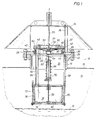
- a fluid pressure relief system in accordance with the present invention is illustrated in which a pressure vessel is shown generally at 10 and comprises a tank preferably having a liquid fluid stored therein with the liquid level shown at 12 and the vapor space 14 in the tank above the liquid.
- Pressure vessel 10 has an outlet generally indicated at 16 including a tubular housing 18 projecting upwardly from pressure vessel 10 and defining an opening illustrated at 20.
- Housing 18 includes an outwardly extending upper horizontal flange 22.
- a safety relief valve is shown generally at 24 supported on flange 22 by suitable nut and bolt combinations 26.
- Safety relief valve 24 may be installed as a retrofit unit on a flange of an existing tank, if desired.
- Relief valve 24 comprises an annular mounting plate or ring 28 having a plurality of spaced openings 30 for receiving nut and bolt combinations 26.
- a plurality of upwardly extending circumferentially spaced supports or brackets 32 have lower flanges supported on mounting plate 28 and secured by nut and bolt combinations 26.
- An upper cover 34 is supported on brackets 32 and support rods or struts 36 extending from plate 28.
- Mounting ring 28 is notched along its inner circumference to form a lower abutment or seat 37 on which a separate inner concentric nozzle or nozzle ring 38 is supported.
- An outer annular groove or slot 39 in nozzle ring 38 receives a pair of semicircular strips 40 and strips 40 are bolted at 41 to mounting ring 28.
- Nozzle ring 38 seats loosely on abutment 37 prior to securement of strips 40 and an O-ring seal 43 seals between nozzle ring 38 and mounting ring 28.
- Nozzle ring 38 forms an upper annular seat 42 and a vent 44. Since nozzle ring 38 is a separate member from mounting ring 28, the transfer of stresses between rings 28, 38 is prevented or minimized thereby minimizing any distortions transferred between the two rings.
- a main pressure relief valve member generally indicated at 46 includes an outer seat ring 48 connected by ribs or spokes 50 to an inner hub 52 and having an inner liner 51.
- Seat ring 48 comprises an annular plate which extends radially outwardly of nozzle ring 38 to provide an increased area exposed to fluid pressure upon opening of relief valve 46.
- An annular counterweight 54 is mounted on seat ring 48 to maintain seat ring 48 in seated closed position on annular seat 42 over vent 44 under a predetermined constant loading with seat ring 48 moved upwardly to an unseated open position at a predetermined fluid pressure within tank 10 for fluid flow through vent 44.
- a limited flexure of nozzle ring 38 relative to mounting plate 28 may occur from seating of valve member 46 on upper seat 42.
- An operating shaft or rod 55 is secured to hub 52 of valve member 46.
- Cross members 58 are secured between rod 55 and counterweight 54 to maintain counterweight 54 in position.
- a vacuum valve member generally indicated at 60 having a hub 62 receiving rod 55 and a generally concave vacuum plate member 64 secured to hub 62.
- Plate member 64 has an annular seat 66 adapted to seat against the lower surface of main valve member 48.
- a vacuum spring 68 extends about a support tube 70 secured to rod 55 to continuously urge vacuum valve member 60 into seating contact against main valve member 46. Support tube 70 may be adjusted along rod 55.
- vacuum valve 64 moves downwardly along rod 55 to an open position relative to main valve member 46 to permit fluid flow from atmosphere through ribs 50 of seat ring 48 and an increase in fluid pressure in tank 10.
- a control means for relief valve member 46 is provided to permit main valve member 46 to remain seated on nozzle ring 38 to minimize leakage of fluid from vent 44 at pressures below MAWP and to permit main valve member 46 to move to full open position at an overpressure less than 20 percent over MAWP.
- the control means is mounted upstream of main valve member 46 generally within the pressure vessel or tank 10.
- the control means comprises fluid pressure responsive means generally indicated at 72 connected to operating rod 55 for controlling the opening and closing of main valve member 46.
- Fluid pressure responsive means 72 includes a piston 74 secured to the lower end of operating rod 55 and mounted for reciprocable movement within a cylinder 76 forming a fluid chamber 78 on one side of piston 74.
- An orifice 80 of a predetermined size is provided in piston 80 to permit fluid communication of fluid chamber 78 with the internal fluid pressure in tank 10.
- Orifice 80 may, for example, be between 0.387 inch and 1.00 inch for a piston having a diameter of around fifteen (15) inches.
- An outlet tube 82 has a lower end connected to cylinder 76 and forms a fluid passage 84 from fluid chamber 78 leading to nozzle ring 38.
- the upper end 86 of outlet tube 82 is positioned adjacent nozzle ring 38 and is spaced slightly from the lower surface of liner 51 on valve member 48 as will be explained further.
- intermediate and lower support rods 88 and 90 support cylinder 76.
- Intermediate rods 88 are connected to upper rods 36 beneath mounting plate 28.
- Lower rods 90 are connected to a lower support plate 92.
- Cylinder 76 includes a cylindrical body 94 resting on plate 92 and an upper end 96 secured to rods 88.
- Upper end 96 has an inner liner 98 secured thereto.
- a suitable guide 100 and securing nut 102 on end 96 receive operating rod 55 for sliding movement.
- Piston 74 has an outer peripheral lip 104 contacting cylindrical body 94 with a minimal frictional contact. Sealing contact with body 94 is not required for adequate functioning of piston 74 especially in view of orifice 80.
- piston 74, cylindrical body 94 and liner 98 are independently mounted and formed of a similar material having the same rate of thermal expansion such as, for example, Teflon, nylon, or polyvinylchloride.
- an expansion gap 106 is provided between upper cylinder end 96 and an upper reduced diameter end 108 of cylindrical body 94.
- Cylindrical body 94, piston 74 and guide 98 expand and contract together as formed of the same material and gap 106 permits expansion of body 94 relative to upper end 96.
- the tolerances between piston 74 and cylindrical body 94 remain constant thereby to maintain the sensitivity of piston 74 at temperature ranges from -20F to + 140F.
- the upper end 86 of outlet tube or pipe 82 is shown as projecting within the area defined by nozzle ring 38 and spaced a distance C from the inner surface of main valve member 46 in the closed position thereof. End 86 is spaced a horizontal distance W from nozzle seat 42 and the nozzle has a height H.
- W is around two (2) inches
- C is around one-eighth (1/8) inch
- H is around four (4) inches for a nozzle ring around twenty-four (24) inches in diameter.
- the distance W should not exceed a maximum of around four (4) inches.
- distance C the greater the distance C, the less effective the fluid pressure differential acting on piston 74.
- Distance C could be as great as distance H but would not be very effective if positioned at the lower end of the nozzle. For best results, distance C should be less than around one-half (1/2) inch. Satisfactory results under certain conditions such as the diameter of nozzle ring 38 and the size of outlet tube 82 may be obtained with distance C as great as around two (2) inches.
- valve member 46 Upon an increase in pressure within tank 10 above MAWP, valve member 46 opens to permit flow through vent 44 as shown in Figure 5 which provides a low pressure zone adjacent nozzle ring 38 resulting from dynamic fluid pressure losses.
- the low fluid pressure is sensed at the upper end 86 of outlet tube 82 and fluid flow then is established through orifice 80, fluid chamber 78, and outlet tube 84.
- the differential pressure resulting from this fluid flow acts against piston 74 to assist in movement of valve member 46 to full open position.
- the size of orifice 80 is utilized to control the sensitivity of main valve member 46 after opening. For example, a smaller orifice size for orifice 80 would provide a larger fluid differential and increase the speed of movement of valve member 46 toward full open position upon an increasing fluid pressure within tank 12.
- a precise and exact full lift overpressure for full opening of main valve member 46 such as 15 percent over the MAWP could be achieved by sizing of orifice 80.
- the safety relief valve of this invention is particularly adapted for use with low fluid pressures.
- the set or crack pressure may be at 1 psi.
- the pressure for the full lift or full open position at one hundred and twenty (120) percent would be 1.2 psi which would result in a pressure of 0.5 psi within piston chamber 78 thereby creating a fluid pressure differential of 0.7 psi across piston 74 to assist piston 74 and rod 55 in an upward movement with minimal frictional contact of lip 104 on piston 74 against the inner surface of cylindrical body 94.
- a negative pressure results in the opening of vacuum valve 60 with concave valve member 64 sliding downwardly along rod 55 to permit fluid flow from atmosphere to the interior of tank 10.
- mechanical force or “mechanical load” as used herein is interpreted as a non-fluid pressure force or load applied against the main valve member to hold the main valve member in seated position on a valve seat.
- the mechanical force or load may be, for example, variable or constant, may be gravity applied from a weight, or may be applied by a mechanical spring.
Landscapes
- Engineering & Computer Science (AREA)
- General Engineering & Computer Science (AREA)
- Mechanical Engineering (AREA)
- Safety Valves (AREA)
Claims (7)
- Strömungsmittel-Druckentlastungssystem für ein Druckgefäß (10) mit einem Ventilsitzelement (42) und einem Haupt-Ventilelement (46), wobei das Haupt-Ventilelement (46) unter einer mechanischen Kraft (54) vorbestimmter Höhe auf dem Ventilsitzelement (42) aufsitzt und auf seiner stromaufwärtigen Seite durchgehend vom Strömungsmitteldruck im Druckgefäß (10) beaufschlagt wird;gekennzeichnet durcheinem Arbeitselement (55), das an einem Ende betrieblich mit dem Haupt-Ventilelement verbunden ist;einem auf den Strömungsmitteldruck ansprechenden Element (74), das am anderen Ende betrieblich mit dem Arbeitselement (55) verbunden ist;einer Strömungsmittelkammer (78) auf einer Seite des druckempfindlichen Elements (74), dessen andere Seite stetig mit dem Inneren des Druckgefäßes (10) ohne wesentliche Drosselung der Strömung zwischen beiden in Strömungsverbindung steht; undeiner Strömungsmittelleitung (82), die einen Strömungskanal (84) zwischen der Strömungsmittelkammer (78) und dem Haupt-Ventilelement (46) bildet, wobei die Strömungsmittelleitung (82) einen mit der Druckmittelkammer (78) in Strömungsverbindung stehenden Zulauf und nahe am Haupt-Ventilelement (46) auf dessen stromaufwärtige Seite am Ventilsitzelement (42) einen Ablauf aufweist, damit beim Öffnen des Haupt-Ventilelements (46) Druckmittel aus der Druckmittelkammer (78) strömen kann, wodurch auf den gegenüberliegenden Seiten des druckempfindlichen Elements (74) bei einer Zunahme des Strömungsmitteldrucks im Druckgefäß (10) infolge einer Druckmittelströmung aus dem Ablauf am Ventilsitzelement (42) eine Druckdifferenz entsteht,eine vom Ventilsitzelement (42) gebildete Ablaßöffnung (44) im oberen Teil des Druckgefäßes (10) undeine Öffnung (80) im druckempfindlichen Element (74), die eine solche vorbestimmte Größe hat, daß eine gedrosselte Druckmittelströmung zwischen der Druckmittelkammer (78) und dem Inneren des Druckgefäßes (10) stattfindet, um eine Druckmittelströmung durch die Druckmittelleitung (82) beim Öffnen des Haupt-Ventilelements (46) zu erlauben und so die Empfindlichkeit des Haupt-Ventilelements (46) nach dem Öffnen zu beeinflussen.
- Druckentlastungssystem nach Anspruch 1, bei dem das Arbeitselement eine Arbeitsstange (55) und das druckempfindliche Element (74) einen Kolben (74) aufweist, der mit der Arbeitsstange (55) verbunden ist, um sich mit diesem und dem Hauptventilelement (46) gemeinsam zu bewegen.
- Druckentlastungssystem nach Anspruch 1, bei dem das druckempfindliche Element (74) einen Kolben (74) aufweist, der in einem Zylinder (76) so angeordnet ist, daß die Druckmittelkammer (78) auf einer Seite des Kolbens (74) gebildet wird.
- Druckentlastungssystem nach Anspruch 1, bei dem ein Düsenring (38) das Ventilsitzelement (42) bildet und auf der Oberseite einen Ventilsitz (42) aufweist, der das Haupt-Ventilelement (46) unter einer mechanischen Kraft (54) vorbestimmter Höhe aufsitzend aufnimmt.
- Druckentlastungssystem nach Anspruch 4, bei dem die Druckmittelleitung (82) einen Auslaß am Düsenring (38) aufweist, der von von dem Haupt-Ventilelement (46) auf dessen stromaufwärtiger Seite geringfügig beabstandet ist und in Strömungsverbindung mit dem Inneren des Druckgefäßes (10) steht.
- Druckentlastungssystem nach Anspruch 1, bei dem auf dem Haupt-Ventilelement (46) ein Gegengewicht (54) angeordnet ist, um das Haupt-Ventilelement (46) unter einer Kraft (54) vorbestimmter Höhe auf dem Ventilsitzelement (42) zu halten.
- Druckentlastungssystem nach Anspruch 1, bei dem das druckempfindliche Element einen Kolben (74) aufweist, der in einem Zylinder angeordnet ist, der die Druckmittelkammer (78) auf einer Seite des Kolbens (74) bildet, wobei der Zylinder einen zylindrischen Körper (76) und über diesem ein oberes Abschlußelement (98) aufweist, der Kolben (74), der zylindrische Körper (76) und das Abschlußelement (98) aus dem gleichen Kunststoff ausgebildet sind, um die gleiche Wärmeausdehnungsrate zu erhalten, und wobei der zylindrische Körper (76) und das obere Abschlußelement (98) nicht aneinander festgelegt sind.
Priority Applications (1)
| Application Number | Priority Date | Filing Date | Title |
|---|---|---|---|
| EP97120573A EP0838618A1 (de) | 1993-02-26 | 1994-01-28 | Sicherheitsventil für Druckgefässe |
Applications Claiming Priority (3)
| Application Number | Priority Date | Filing Date | Title |
|---|---|---|---|
| US08/023,554 US5307831A (en) | 1992-06-29 | 1993-02-26 | Safety relief valve for pressure vessels |
| US23554 | 1993-02-26 | ||
| PCT/US1994/001022 WO1994019631A1 (en) | 1993-02-26 | 1994-01-28 | Safety relief valve for pressure vessels |
Related Child Applications (1)
| Application Number | Title | Priority Date | Filing Date |
|---|---|---|---|
| EP97120573A Division EP0838618A1 (de) | 1993-02-26 | 1994-01-28 | Sicherheitsventil für Druckgefässe |
Publications (3)
| Publication Number | Publication Date |
|---|---|
| EP0686241A1 EP0686241A1 (de) | 1995-12-13 |
| EP0686241A4 EP0686241A4 (de) | 1996-06-05 |
| EP0686241B1 true EP0686241B1 (de) | 1998-07-29 |
Family
ID=21815815
Family Applications (2)
| Application Number | Title | Priority Date | Filing Date |
|---|---|---|---|
| EP19940908663 Expired - Lifetime EP0686241B1 (de) | 1993-02-26 | 1994-01-28 | Sicherheitsventil für drückgefässe |
| EP97120573A Withdrawn EP0838618A1 (de) | 1993-02-26 | 1994-01-28 | Sicherheitsventil für Druckgefässe |
Family Applications After (1)
| Application Number | Title | Priority Date | Filing Date |
|---|---|---|---|
| EP97120573A Withdrawn EP0838618A1 (de) | 1993-02-26 | 1994-01-28 | Sicherheitsventil für Druckgefässe |
Country Status (5)
| Country | Link |
|---|---|
| US (1) | US5307831A (de) |
| EP (2) | EP0686241B1 (de) |
| CA (1) | CA2156817A1 (de) |
| DE (1) | DE69412076T2 (de) |
| WO (1) | WO1994019631A1 (de) |
Families Citing this family (9)
| Publication number | Priority date | Publication date | Assignee | Title |
|---|---|---|---|---|
| DE10318310A1 (de) * | 2003-04-14 | 2004-11-25 | Xaver Lipp | Vorrichtung zum Öffnen eines Ventils, insbesondere eines Lufteinlaßventils oder Gasauslaßventils eines Gär-oder Faulbehälters |
| WO2004090395A1 (de) * | 2003-04-14 | 2004-10-21 | Xaver Lipp | Vorrichtung zum öffnen eines ventils, insbesondere eines lufteinlassventils oder gasauslassventils eines gär-oder faulbehälters |
| FR2910583B1 (fr) * | 2006-12-26 | 2011-05-06 | Etablissements Chpolansky | Soupape de securite a basse pression, et systemes de securisation l'incorporant |
| RU2398150C1 (ru) * | 2009-07-20 | 2010-08-27 | Олег Савельевич Кочетов | Клапан предохранительный гидравлический |
| US8992695B2 (en) * | 2010-06-29 | 2015-03-31 | Steris, Inc. | Washer chamber pressure-relief assembly |
| RU2472999C2 (ru) * | 2011-02-03 | 2013-01-20 | Олег Савельевич Кочетов | Предохранительный огнезащитный клапан |
| RU2472998C2 (ru) * | 2011-02-03 | 2013-01-20 | Олег Савельевич Кочетов | Предохранительный гидравлический клапан |
| RU2514808C2 (ru) * | 2012-05-04 | 2014-05-10 | Саратовское акционерное производственно-коммерческое открытое общество "НЕФТЕМАШ" ОАО "НЕФТЕМАШ"-САПКОН | Клапан дыхательно-предохранительный |
| GB2555416B (en) * | 2016-10-26 | 2018-11-28 | Fairfax 3D Design Ltd | Fuel tank pressure relief valve |
Family Cites Families (12)
| Publication number | Priority date | Publication date | Assignee | Title |
|---|---|---|---|---|
| US3126909A (en) * | 1964-03-31 | Relief valve | ||
| US1620719A (en) * | 1923-05-14 | 1927-03-15 | Gustin Bacon Mfg Co | Relief valve for excessive-pressure vapor tanks and lines |
| US1916767A (en) * | 1927-12-13 | 1933-07-04 | Mason Harold Lyall | Valve |
| US2214963A (en) * | 1937-01-16 | 1940-09-17 | Albert E Jurs | Pressure relief valve |
| US2969084A (en) * | 1958-04-21 | 1961-01-24 | Racine Hydraulics And Machiner | Pressure responsive valve |
| US3477456A (en) * | 1967-04-03 | 1969-11-11 | Anderson Greenwood & Co | Valve |
| US3918418A (en) * | 1973-04-06 | 1975-11-11 | Brunswick Corp | Marine engine cooling system employing a thermostatic valve means and a pressure relief valve means |
| US3881505A (en) * | 1974-03-04 | 1975-05-06 | Vapor Corp | Pressure responsive pilot valve |
| US4410005A (en) * | 1981-02-13 | 1983-10-18 | Vapor Corporation | Pilot operated relief valve |
| US4705065A (en) * | 1986-05-16 | 1987-11-10 | Anderson, Greenwood & Company | Safety relief system for control or vent valves |
| SE458802B (sv) * | 1987-04-03 | 1989-05-08 | Stifab Ab | Regleranordning foer instaellning av ett spjaell i en ventilationskanal |
| US5064169A (en) * | 1990-03-30 | 1991-11-12 | Keystone International Holdings Corp. | Shock absorbing means for flow control devices |
-
1993
- 1993-02-26 US US08/023,554 patent/US5307831A/en not_active Expired - Lifetime
-
1994
- 1994-01-28 EP EP19940908663 patent/EP0686241B1/de not_active Expired - Lifetime
- 1994-01-28 WO PCT/US1994/001022 patent/WO1994019631A1/en not_active Ceased
- 1994-01-28 CA CA 2156817 patent/CA2156817A1/en not_active Abandoned
- 1994-01-28 EP EP97120573A patent/EP0838618A1/de not_active Withdrawn
- 1994-01-28 DE DE69412076T patent/DE69412076T2/de not_active Expired - Fee Related
Also Published As
| Publication number | Publication date |
|---|---|
| DE69412076T2 (de) | 1998-12-03 |
| CA2156817A1 (en) | 1994-09-01 |
| EP0838618A1 (de) | 1998-04-29 |
| EP0686241A4 (de) | 1996-06-05 |
| WO1994019631A1 (en) | 1994-09-01 |
| US5307831A (en) | 1994-05-03 |
| DE69412076D1 (de) | 1998-09-03 |
| EP0686241A1 (de) | 1995-12-13 |
Similar Documents
| Publication | Publication Date | Title |
|---|---|---|
| EP0648318B1 (de) | Druckentlastungsvorrichtung für druckbehälter | |
| US6318406B1 (en) | Pilot operated relief valve | |
| US4705065A (en) | Safety relief system for control or vent valves | |
| US6056005A (en) | Vent valve with liquid seal | |
| EP0686241B1 (de) | Sicherheitsventil für drückgefässe | |
| KR100198691B1 (ko) | 차량 연료 시스템용 연료 증기 방출 밸브 | |
| AU2001249174A1 (en) | Pilot operated relief valve | |
| US4130130A (en) | Valve with variable secondary orifice | |
| US4848397A (en) | High temperature safety relief system | |
| EP0468621B1 (de) | Vorsteuerventil für Regelventile und Betriebsverfahren | |
| CA2187601C (en) | Pilot operated fluid valve | |
| US4958656A (en) | Pressure relief valve | |
| US3702142A (en) | Safety valve having back pressure compensator | |
| US4870989A (en) | High temperature safety relief system | |
| US5515884A (en) | Multi-media safety relief valve | |
| US5094267A (en) | Pressure balanced valve spindle | |
| US5577524A (en) | Large diameter resettable rupture pin relief valve | |
| EP0558193B1 (de) | Druckentlastungsventil mit Hilfsdruckvorrichtung | |
| US5890508A (en) | Main relief valve for safety relief system | |
| US4865074A (en) | High temperature safety relief system | |
| US4245663A (en) | Valve with condensate recovery device | |
| CA1039616A (en) | Pilot valve operator for safety relief valve | |
| US4687078A (en) | Hydraulic elevator system | |
| US4412555A (en) | Over pressure release valve for a hydraulic installation |
Legal Events
| Date | Code | Title | Description |
|---|---|---|---|
| PUAI | Public reference made under article 153(3) epc to a published international application that has entered the european phase |
Free format text: ORIGINAL CODE: 0009012 |
|
| 17P | Request for examination filed |
Effective date: 19950828 |
|
| AK | Designated contracting states |
Kind code of ref document: A1 Designated state(s): DE FR GB |
|
| A4 | Supplementary search report drawn up and despatched |
Effective date: 19960422 |
|
| AK | Designated contracting states |
Kind code of ref document: A4 Designated state(s): DE FR GB |
|
| 17Q | First examination report despatched |
Effective date: 19961031 |
|
| GRAG | Despatch of communication of intention to grant |
Free format text: ORIGINAL CODE: EPIDOS AGRA |
|
| GRAG | Despatch of communication of intention to grant |
Free format text: ORIGINAL CODE: EPIDOS AGRA |
|
| GRAH | Despatch of communication of intention to grant a patent |
Free format text: ORIGINAL CODE: EPIDOS IGRA |
|
| GRAH | Despatch of communication of intention to grant a patent |
Free format text: ORIGINAL CODE: EPIDOS IGRA |
|
| GRAA | (expected) grant |
Free format text: ORIGINAL CODE: 0009210 |
|
| AK | Designated contracting states |
Kind code of ref document: B1 Designated state(s): DE FR GB |
|
| ET | Fr: translation filed | ||
| REF | Corresponds to: |
Ref document number: 69412076 Country of ref document: DE Date of ref document: 19980903 |
|
| PGFP | Annual fee paid to national office [announced via postgrant information from national office to epo] |
Ref country code: GB Payment date: 19981231 Year of fee payment: 6 Ref country code: FR Payment date: 19981231 Year of fee payment: 6 |
|
| PGFP | Annual fee paid to national office [announced via postgrant information from national office to epo] |
Ref country code: DE Payment date: 19990104 Year of fee payment: 6 |
|
| PLBE | No opposition filed within time limit |
Free format text: ORIGINAL CODE: 0009261 |
|
| STAA | Information on the status of an ep patent application or granted ep patent |
Free format text: STATUS: NO OPPOSITION FILED WITHIN TIME LIMIT |
|
| 26N | No opposition filed | ||
| PG25 | Lapsed in a contracting state [announced via postgrant information from national office to epo] |
Ref country code: GB Free format text: LAPSE BECAUSE OF NON-PAYMENT OF DUE FEES Effective date: 20000128 |
|
| GBPC | Gb: european patent ceased through non-payment of renewal fee |
Effective date: 20000128 |
|
| PG25 | Lapsed in a contracting state [announced via postgrant information from national office to epo] |
Ref country code: FR Free format text: LAPSE BECAUSE OF NON-PAYMENT OF DUE FEES Effective date: 20000929 |
|
| PG25 | Lapsed in a contracting state [announced via postgrant information from national office to epo] |
Ref country code: DE Free format text: LAPSE BECAUSE OF NON-PAYMENT OF DUE FEES Effective date: 20001101 |
|
| REG | Reference to a national code |
Ref country code: FR Ref legal event code: ST |