EP0684530A1 - Apparatus and method for conditioning an image formed from a liquid developer - Google Patents
Apparatus and method for conditioning an image formed from a liquid developer Download PDFInfo
- Publication number
- EP0684530A1 EP0684530A1 EP95303065A EP95303065A EP0684530A1 EP 0684530 A1 EP0684530 A1 EP 0684530A1 EP 95303065 A EP95303065 A EP 95303065A EP 95303065 A EP95303065 A EP 95303065A EP 0684530 A1 EP0684530 A1 EP 0684530A1
- Authority
- EP
- European Patent Office
- Prior art keywords
- roller
- liquid carrier
- image
- toner particles
- liquid
- Prior art date
- Legal status (The legal status is an assumption and is not a legal conclusion. Google has not performed a legal analysis and makes no representation as to the accuracy of the status listed.)
- Granted
Links
- 239000007788 liquid Substances 0.000 title claims abstract description 105
- 230000003750 conditioning effect Effects 0.000 title claims description 6
- 238000000034 method Methods 0.000 title abstract description 34
- 239000002245 particle Substances 0.000 claims abstract description 51
- 239000000463 material Substances 0.000 claims description 38
- 238000010521 absorption reaction Methods 0.000 claims description 25
- 230000008569 process Effects 0.000 abstract description 23
- 230000035699 permeability Effects 0.000 abstract description 4
- 239000006260 foam Substances 0.000 description 12
- 239000007787 solid Substances 0.000 description 11
- 239000011148 porous material Substances 0.000 description 10
- XLYOFNOQVPJJNP-UHFFFAOYSA-N water Substances O XLYOFNOQVPJJNP-UHFFFAOYSA-N 0.000 description 8
- 230000002745 absorbent Effects 0.000 description 6
- 239000002250 absorbent Substances 0.000 description 6
- 230000001846 repelling effect Effects 0.000 description 6
- 238000004519 manufacturing process Methods 0.000 description 5
- 239000004215 Carbon black (E152) Substances 0.000 description 4
- 239000000969 carrier Substances 0.000 description 4
- 239000012530 fluid Substances 0.000 description 4
- 229930195733 hydrocarbon Natural products 0.000 description 4
- 150000002430 hydrocarbons Chemical class 0.000 description 4
- 230000003319 supportive effect Effects 0.000 description 4
- 238000004140 cleaning Methods 0.000 description 3
- 230000003247 decreasing effect Effects 0.000 description 3
- 230000005684 electric field Effects 0.000 description 3
- 230000002401 inhibitory effect Effects 0.000 description 3
- 239000002184 metal Substances 0.000 description 3
- 229910052751 metal Inorganic materials 0.000 description 3
- 229920002635 polyurethane Polymers 0.000 description 3
- 239000004814 polyurethane Substances 0.000 description 3
- 229910001220 stainless steel Inorganic materials 0.000 description 3
- 239000010935 stainless steel Substances 0.000 description 3
- 230000006835 compression Effects 0.000 description 2
- 238000007906 compression Methods 0.000 description 2
- 239000011231 conductive filler Substances 0.000 description 2
- 239000002270 dispersing agent Substances 0.000 description 2
- 229920001971 elastomer Polymers 0.000 description 2
- 230000008020 evaporation Effects 0.000 description 2
- 238000001704 evaporation Methods 0.000 description 2
- NBVXSUQYWXRMNV-UHFFFAOYSA-N fluoromethane Chemical compound FC NBVXSUQYWXRMNV-UHFFFAOYSA-N 0.000 description 2
- 239000006261 foam material Substances 0.000 description 2
- 230000036541 health Effects 0.000 description 2
- 238000003384 imaging method Methods 0.000 description 2
- 235000019645 odor Nutrition 0.000 description 2
- 230000003287 optical effect Effects 0.000 description 2
- 239000000049 pigment Substances 0.000 description 2
- 239000000758 substrate Substances 0.000 description 2
- 230000007723 transport mechanism Effects 0.000 description 2
- 229910000906 Bronze Inorganic materials 0.000 description 1
- RYGMFSIKBFXOCR-UHFFFAOYSA-N Copper Chemical compound [Cu] RYGMFSIKBFXOCR-UHFFFAOYSA-N 0.000 description 1
- 229920000877 Melamine resin Polymers 0.000 description 1
- 239000004642 Polyimide Substances 0.000 description 1
- 229920005830 Polyurethane Foam Polymers 0.000 description 1
- 241001620634 Roger Species 0.000 description 1
- 150000001336 alkenes Chemical class 0.000 description 1
- 230000004888 barrier function Effects 0.000 description 1
- 239000011230 binding agent Substances 0.000 description 1
- 230000015572 biosynthetic process Effects 0.000 description 1
- 239000010974 bronze Substances 0.000 description 1
- 239000006229 carbon black Substances 0.000 description 1
- 239000012876 carrier material Substances 0.000 description 1
- 239000000919 ceramic Substances 0.000 description 1
- 239000007795 chemical reaction product Substances 0.000 description 1
- 239000003086 colorant Substances 0.000 description 1
- 230000001143 conditioned effect Effects 0.000 description 1
- 239000004020 conductor Substances 0.000 description 1
- 229910052802 copper Inorganic materials 0.000 description 1
- 239000010949 copper Substances 0.000 description 1
- KUNSUQLRTQLHQQ-UHFFFAOYSA-N copper tin Chemical compound [Cu].[Sn] KUNSUQLRTQLHQQ-UHFFFAOYSA-N 0.000 description 1
- 238000005553 drilling Methods 0.000 description 1
- 239000000806 elastomer Substances 0.000 description 1
- 239000013536 elastomeric material Substances 0.000 description 1
- 238000001962 electrophoresis Methods 0.000 description 1
- 230000007613 environmental effect Effects 0.000 description 1
- 238000005530 etching Methods 0.000 description 1
- 239000000945 filler Substances 0.000 description 1
- 239000012634 fragment Substances 0.000 description 1
- 239000008187 granular material Substances 0.000 description 1
- 238000005286 illumination Methods 0.000 description 1
- 230000001771 impaired effect Effects 0.000 description 1
- 150000002500 ions Chemical class 0.000 description 1
- 239000011344 liquid material Substances 0.000 description 1
- JDSHMPZPIAZGSV-UHFFFAOYSA-N melamine Chemical compound NC1=NC(N)=NC(N)=N1 JDSHMPZPIAZGSV-UHFFFAOYSA-N 0.000 description 1
- 239000012528 membrane Substances 0.000 description 1
- 150000002739 metals Chemical class 0.000 description 1
- 239000002480 mineral oil Substances 0.000 description 1
- 235000010446 mineral oil Nutrition 0.000 description 1
- 239000000203 mixture Substances 0.000 description 1
- 239000012466 permeate Substances 0.000 description 1
- 108091008695 photoreceptors Proteins 0.000 description 1
- 239000004033 plastic Substances 0.000 description 1
- 229920003023 plastic Polymers 0.000 description 1
- 229920001721 polyimide Polymers 0.000 description 1
- 229920000642 polymer Polymers 0.000 description 1
- 229920001296 polysiloxane Polymers 0.000 description 1
- 239000011496 polyurethane foam Substances 0.000 description 1
- 230000001681 protective effect Effects 0.000 description 1
- 230000002829 reductive effect Effects 0.000 description 1
- 239000007921 spray Substances 0.000 description 1
- 229920003002 synthetic resin Polymers 0.000 description 1
- 239000000057 synthetic resin Substances 0.000 description 1
- BFKJFAAPBSQJPD-UHFFFAOYSA-N tetrafluoroethene Chemical group FC(F)=C(F)F BFKJFAAPBSQJPD-UHFFFAOYSA-N 0.000 description 1
Images


Classifications
-
- G—PHYSICS
- G03—PHOTOGRAPHY; CINEMATOGRAPHY; ANALOGOUS TECHNIQUES USING WAVES OTHER THAN OPTICAL WAVES; ELECTROGRAPHY; HOLOGRAPHY
- G03G—ELECTROGRAPHY; ELECTROPHOTOGRAPHY; MAGNETOGRAPHY
- G03G15/00—Apparatus for electrographic processes using a charge pattern
- G03G15/14—Apparatus for electrographic processes using a charge pattern for transferring a pattern to a second base
- G03G15/16—Apparatus for electrographic processes using a charge pattern for transferring a pattern to a second base of a toner pattern, e.g. a powder pattern, e.g. magnetic transfer
- G03G15/1605—Apparatus for electrographic processes using a charge pattern for transferring a pattern to a second base of a toner pattern, e.g. a powder pattern, e.g. magnetic transfer using at least one intermediate support
- G03G15/161—Apparatus for electrographic processes using a charge pattern for transferring a pattern to a second base of a toner pattern, e.g. a powder pattern, e.g. magnetic transfer using at least one intermediate support with means for handling the intermediate support, e.g. heating, cleaning, coating with a transfer agent
-
- G—PHYSICS
- G03—PHOTOGRAPHY; CINEMATOGRAPHY; ANALOGOUS TECHNIQUES USING WAVES OTHER THAN OPTICAL WAVES; ELECTROGRAPHY; HOLOGRAPHY
- G03G—ELECTROGRAPHY; ELECTROPHOTOGRAPHY; MAGNETOGRAPHY
- G03G15/00—Apparatus for electrographic processes using a charge pattern
- G03G15/06—Apparatus for electrographic processes using a charge pattern for developing
- G03G15/10—Apparatus for electrographic processes using a charge pattern for developing using a liquid developer
- G03G15/11—Removing excess liquid developer, e.g. by heat
Definitions
- This invention relates to a method and apparatus for conditioning an image formed from a liquid developer, and more particularly to a method and apparatus for removing toner dispersant from an image formed from a liquid developer.
- a typical electrostatographic printing machine employs an imaging member that is exposed to an image to be printed. Exposure of the imaging member records an electrostatic latent image on it corresponding to the informational areas contained within the image to be printed The latent image is developed by bringing a developer material into contact therewith. The developed image recorded on the photoconductive member is transferred to a copy sheet such as paper, either directly or via an intermediate transport member. The developed image on the copy sheet is generally subjected to heat and/or pressure to permanently fuse it thereto.
- developer material Two types are typically employed in electrostatographic printing machines.
- One type of developer material is known as dry developer material and comprises toner particles or carrier granules having toner particles adhering triboelectrically thereto.
- Another type of developer material is a liquid material comprising a liquid carrier or dispersant having toner particles dispersed therein.
- Liquid developer typically contains about 2 percent by weight of fine solid particulate toner material dispersed in the liquid carrier
- the liquid carrier is typically a hydrocarbon.
- the developed image on the photoreceptor contains about 12 weight percent of particulate toner in liquid hydrocarbon carrier.
- the image should be conditioned, i.e. percent solids in liquid should be increased by removing liquid carrier from the image while preventing toner particles from departing the image.
- the percentage of solids in the liquid should be increased to in the range of 25 to 75 percent.
- Increase in percent solids may be achieved by removing excess liquid carrier with a porous blotter in the form of a roller or belt (hereinafter collectively referred to as "roller"), typically positioned with respect to the photoconductive member retaining the latent image.
- roller typically positioned with respect to the photoconductive member retaining the latent image.
- the developed image on the intermediate belt should again be blotted to further increase the percentage of toner solids, so that the amount of liquid on the final copy sheet is minimized, and a well defined, high quality image is produced.
- Polymers such as various polyurethanes, olefins, tetrafluoroethylene, and various elastomers, may be processed into open cell poromeric foam material appropriate for use in blotter roller applications, using the teachings, for example, in US-A-3,696,180; 3,729,536; 3,860,680; 3,968,292; 4,157,424, and other methods known in the art.
- Conductive fillers, organic and inorganic, ionic or electronic may be added to regulate the poromeric material conductivity.
- This skin covering generally tends to have pores of a smaller size and a lesser quantity than the open cell inner foam material, and serves as a structural support and protective covering for the inner foam layer
- the skin covering must have a porosity sufficient to absorb liquid carrier from the developed image, however, should have a smooth, glossy surface texture so that toner particles from the developed image are prevented from departing the image and embedding into the irregularities found on a more textured blotter roller skin surface. It is important to prevent toner particles from entering the blotter roller, as the pores of the roller become blocked and the rate of absorption of the liquid carrier from the developed image is slowed.
- Image quality is impaired when toner particles depart therefrom, and frequent cleaning and/or replacement of the roller is necessitated.
- a bias applied to the blotter roller having the same polarity as the toner particles of the developed image presents a repelling force between the toner and the roller, further preventing toner particles from entering the blotter roller.
- a shortcoming of this type of blotter roller is that the skin covering tends to retard fluid flow through the poromeric material, even in systems having a vacuum assist for removal of the liquid from the roller. Therefore, blotter rollers are often unable to achieve the desired toner solid weight percentage at the required process speed for a high volume production color printer. Process speed and/or image quality have been restricted by prior art blotting devices used in liquid developing systems. This shortcoming is even more apparent due to the increased tendency to use liquid carriers that are less volatile, for environmental, health and safety reasons. Less volatile liquid carriers have a decreased vapor pressure rate, and thereby give off less offensive odors and expose less vapor into the atmosphere during the image forming process. Pollution and potential health risks to individuals working near the machine are thereby reduced. However, due to the lower evaporation rates of these liquid carriers, there is provided yet an increased need for a system with an increased capacity for liquid carrier absorption from the developed image.
- an improved printing machine of the type having a surface, with an image developed with a liquid developer comprising liquid carrier and toner particles, and a roller for removing liquid carrier therefrom before transferring the developed image from the surface to a final copy sheet.
- the roller comprises an absorption material adapted to absorb the liquid carrier, and a covering in contact with a portion of the absorption material.
- the covering has a smooth surface and is substantially impervious to toner particles and pervious to liquid carrier so as to inhibit toner particles from departing the image.
- the covering also has a plurality of perforations therein to permit liquid carrier to pass through to the absorption material.
- a roller for conditioning an image formed from a liquid developer including liquid carrier and toner particles.
- the roller comprises an absorption material adapted to absorb the liquid carrier, and a covering in contact with a portion of the absorption material.
- the covering has a smooth surface and is substantially impervious to toner particles and pervious to liquid carrier so as to inhibit toner particles from departing the image.
- the covering also has a plurality of perforations therein to permit liquid carrier to pass through to the absorption material.
- a method of fabricating a roller for conditioning an image formed from a liquid developer comprising liquid carrier and toner particles comprises the step of selecting a cover having a smooth surface that is substantially impervious to toner particles and pervious to liquid carrier so that toner particles are inhibited from departing the image.
- the method also includes the steps of perforating the cover with a plurality of apertures, and then placing the cover and a portion of an absorption material in contact with one another.
- printing machine 1 employs belt 2 having a photoconductive surface deposited on a conductive substrate. Initially, belt 2 passes through charging station A. At charging station A, a corona generating device 7 charges the photoconductive surface of belt 2 to a relatively high, substantially uniform potential.
- an original document 8 is placed upon a transparent support platen 9.
- An illumination assembly indicated generally by the reference numeral 10, illuminates the original document 8 on platen 9 to produce image rays corresponding to the document information areas.
- the image rays are projected by means of an optical system onto the charged portion of the photoconductive surface. The light image dissipates the charge in selected areas to record an electrostatic latent image on the photoconductive surface corresponding to the original document informational areas.
- belt 2 advances the electrostatic latent image to development station C.
- roller 11 rotating in the direction of arrow 12, advances a liquid developer material 13 from the chamber of housing 14 to development zone 17.
- An electrode 16 positioned before the entrance to development zone 17 is electrically biased to generate an AC field just prior to the entrance to development zone 17 so as to disperse the toner particles substantially uniformly throughout the liquid carrier.
- the toner particles, disseminated through the liquid carrier, pass by electrophoresis to the electrostatic latent image.
- the charge of the toner particles is opposite in polarity to the charge on the photoconductive surface.
- the insulating liquid carrier may be a hydrocarbon liquid although other insulating liquids may also be employed.
- a suitable hydrocarbon liquid is an lsopar which is a trademark of the Exxon Corporation.
- liquid carriers such as mineral oil whose structural properties are less volatile, and thereby emit a lower amount of vapor into the atmosphere, consequently emitting fewer harmful and offensive odors.
- the toner particles comprise a binder and a pigment.
- the pigment may be carbon black.
- any suitable liquid development material may be employed.
- Development station C includes porous roller 18 having perforations (shown in Figures 3 through 6) through the roller skin covering.
- Roller 18 receives the developed image on belt 2 and conditions the image by reducing fluid content while inhibiting the departure of toner particles from the image. An increase in percent solids is thereby provided to the developed image, thereby improving the quality of the developed image.
- Porous roller 18 will be described hereinafter with reference to Figure 2, and in detail with reference to Figures 3 - 6.
- Porous roller 18 operates in conjunction with vacuum 19 for removal of liquid from the roller.
- a roller in pressure against the blotter roller, may be used in conjunction with or in the place of the vacuum, to squeeze the absorbed liquid carrier from the blotter roller for deposit into a receptacle
- a blotter roller of the type having a pressure roller for removal of liquid from the blotter roller is described in, for example, copending continuing application for U.S. patent, Serial Number 08/082,141, having a common assignee as the present application, the relevant portions of which are hereby incorporated herein by reference.
- a bias voltage 53 is applied to an electroconductive roller creating an electric field having the same sign polarity as the toner particles, thereby repelling the toner particles and inhibiting their entry into the roller 18.
- the blotter roller of the present invention may accompany the blotter roller in conjunction with the photoconductive belt, and/or in conjunction with the intermediate transfer belt as will be described with reference to Figure 2.
- the present invention may also find useful application where the liquid absorbing roller is in the form of a belt rotated by two or more internal rollers, whereby excess liquid carrier is absorbed through a foam layer and a skin covering having perforations formed therethrough.
- a belt used for collecting excess liquid from a region of liquid developed images is described in US-A-4,299,902 and 4,258,115, the relevant portions of which are hereby incorporated by reference herein.
- roller 18 rotates in direction 20 to impose against the "wet" image on belt 2.
- the porous body of roller 18 absorbs excess liquid from the surface of the image through the skin covering pores and perforations.
- Vacuum 19 located on one end of the central cavity of the roller, draws liquid that has permeated through roller 18 out through the cavity and deposits the liquid in a receptacle or some other location which will allow for either disposal or recirculation of the liquid carrier.
- Porous roller 18, discharged of excess liquid continues to rotate in direction 20 to provide a continuous absorption of liquid from image on belt 2.
- belt 2 advances the developed image to transfer station D
- transfer station D a sheet of support material 22 is advanced from stack 23 by a sheet transport mechanism, indicated generally by the reference numeral 24.
- Transfer station D includes a corona generating device 25 which sprays ions onto the backside of the sheet of support material 22. This attracts the developed image from the photoconductive surface of belt 2 to copy sheet 22.
- conveyor belt 26 moves the copy sheet 22 to fusing station E.
- Fusing station E includes a fuser assembly indicated generally by the reference numeral 27, which permanently fuses the developed image to the copy sheet 22.
- Fuser assembly 27 includes a heated fuser roll 28 and back-up pressure roll 29 resiliently urged into engagement with one another to form a nip through which the copy sheet 22 passes. After fusing, the finished copy sheet 22 is discharged to output tray 30 for removal by the machine operator.
- FIG 2 is a schematic representation of a portion of another printing machine which employs a moving image carrying belt, from which an image is transferred to an intermediate belt. Electrostatographic reproduction apparatus utilizing intermediate belts are described, for example, in US-A-4,183,658; 4,684,238; 4,690,539; and 5,119,140.
- elements that are identical to elements in Figure 1 are identified with like reference numerals.
- a printing machine employing belt 2 having a photoconductive surface deposited on a conductive substrate.
- Roller 3 rotates and advances belt 2 in the direction of arrow 6.
- Belt 2 passes through charging station A where a corona generating device 7 charges the photoconductive surface of the belt 2.
- the charge portion of belt 2 is advanced to exposure station B where image rays from an original document are projected by means of an optical system onto the charged portion of the photoconductive surface to record an electrostatic latent image.
- belt 2 advances to development station C.
- roller 11 advances a liquid developer material 13 from the chamber of housing 14 to development zone 17.
- Electrode 16 positioned before the entrance to development zone 17 is electrically biased so as to disperse the toner particles substantially uniformly throughout the liquid carrier.
- Development station C includes porous blotter roller 18 having perforations through the skin surface. Roller 18 receives the developed image on belt 2 and conditions the image by reducing fluid content while inhibiting the departure of toner particles from the image. The percent solids in the image is thereby increased
- the roller 18 operates in conjunction with vacuum 19 for removal of the liquid carrier.
- a bias voltage is applied to roller 1850 that a repelling force is present to prevent toner particles from leaving the photoconductive surface and entering the roller 18.
- belt 2 advances the developed image to transfer station D.
- transfer station D the developed liquid image is electrostatically transferred to an intermediate member or belt indicated generally by the reference numeral 35.
- Belt 35 is entrained about spaced rollers 36 and 37.
- Belt 35 moves in the direction of arrow 38.
- Bias transfer roller 39 imposes belt 35 against belt 2 to assure image transfer to the intermediate belt 35.
- the porous blotter roller 40 having perforations through the roller skin covering, receives the developed image on belt 35 and reduces fluid content while preventing toner particles from departing from the image, so that percent solids of the image is further increased.
- the roller 40 increases percent solids to about 25 to 75 wt.% by removing excess liquid carrier in this region.
- the roller of the present invention may be used for absorbing liquid carrier at an increased rate from an image in a system having an intermediate transfer belt. Consequently, the percent particles on the image is increased, thereby increasing process speed for color imagery.
- roller 40 rotates in direction 41 to impose against the image on belt 35.
- the porous body of roller 40 absorbs liquid from the surface of the image.
- the absorbed liquid permeates through roller 40 and into the inner hollow cavity 49, where a vacuum draws the liquid from the roller 40 into a liquid receptacle or some other location which will allow for either disposal or recirculation of the liquid carrier.
- Porous roller 40 discharged of excess liquid, continues to rotate in direction 41 to provide a continuous absorption of liquid from images on transfer belt 35.
- a bias voltage 53 is applied to the roller to establish a repelling force against the toner particles so that toner particles are prevented from entering the roller 40.
- Roller 40 may be used in conjunction with a pressure roller (not shown) to remove the liquid that has been absorbed into the roller 40.
- Belt 35 then advances the developed image to transfer station D.
- a sheet of support material 22 is advanced from stack 23 by a sheet transport mechanism, indicated generally by the reference numeral 24.
- the developed image from the photoconductive surface of belt 35 is attracted to copy sheet 22.
- conveyor belt 45 moves the copy sheet 22 to the discharge output tray 30.
- roller 50 comprises a rigid porous supportive core 46.
- the core 46 is in the form of a tube, having a hollow cavity 49 throughout the length of the roller.
- a conformable microporous roller 47, and a skin covering 48 having a pattern of apertures or perforations 52 therethrough is provided around the core 46.
- a vacuum 19 draws the liquid carrier that has permeated through roller 50 into cavity 49.
- a high voltage bias supply 53 is connected between the belt 2 and the conductive core 46 of roller 50 for providing a bias with the same charge as that of the toner particles. The bias continuously repels the toner particles of the image on belt from the roller, while the liquid carrier is absorbed into the roller 50.
- a pressure controller (not shown) may be used in association with the roller to provide a positive or negative pressure to the roller.
- the porous supportive core 46 can comprise a material selected from the group consisting of sintered metal, plastic and ceramic.
- the supportive core 46 comprises a sintered metal
- exemplary metals include stainless steel, copper and bronze.
- the material is electroconductive, either by itself, or in combination with another conductive material, so that a bias 53 can be applied thereto, and an electrical field will result in a repelling force against the toner particles in the image.
- the pores of the supportive core generally may be of a diameter of 2,500 microns or less.
- the conformable microporous foam roller 47 is characterized by open cells forming the layer.
- the conformable foam roller 47 may comprise an absorbent polymeric and elastomeric material with incorporated conductive filler or dissipative filler.
- the conformable roller 47 is characterized by a durometer of from 10 to 90 Shore A, preferably from 20 to 60 Shore A, and has a thickness of 1.0 mils to 500 mils, preferably, a thickness of about 40 mils to 250 mils.
- the absorption material of the microporous roller 47 may be any suitable material, preferably a foam such as one selected from the group consisting of Polyurethane, Silicone, Fluorocarbon, Polyimide, Melamine, and rubber, such as Permair@ (a microporous polyurethane material available from Porvair Ltd., England), and Tetratex@ (a microporous semipermeable fluorocarbon membrane available from Tetratec Corp., Pennsylvania).
- the absorbent material is resistive so that the electric field created by the bias 53 applied to the core 46 further enhances the repelling action of the toner particles from the roller 50.
- a suitable level of resistivity of the absorbent material is in the range of 10- 5 to 10- 11 ohm-cm, and is preferably in the range of 10- 6 to 10- 9 ohm-cm.
- the absorbent material must, of course, be compatible with whatever liquid carrier material is used.
- the open cell pores of the absorbent material generally may be less than 1,000 microns in diameter, and preferably should be in the range of about 5 to about 300 microns, although the end product may use pore sizes outside these limits. For example, very small pores of a micron or less may be used to absorb liquid carrier from an image, however, an increased pressure would then be required to extract an equivalent amount of liquid as that of a roller having larger size pores.
- the vacuum system 19 assists in drawing liquid carrier through the blotter roller and into the cavity 49, where it is then removed to a collection location.
- the vacuum system pressure must be adjusted so as to remove only liquid carrier from the image, and not have so strong a suction force so as to also remove the toner.
- the vacuum pressure and the speed of the roller 50 may in one preferred embodiment be selected to keep the pores of roller filled with liquid carrier.
- the perforations 52 formed through the blotter roller skin covering 48 of the present invention increase the rate of absorption of the liquid carrier, and therefore, the overall process speed of the image forming process, particularly when coupled with an increase in vacuum pressure.
- a blotter roller having an absorbent foam layer made from an Endur-C polyurethane foam from the Roger's Corporation, and having a non-perforated skin covering showed an increase in permeability of over 85 times, when the skin covering was uniformly laser perforated with holes having an average diameter of 250 microns.
- the skin covering 48 has a smooth, glossy surface texture with micropores which are generally of a smaller size than the toner particles of the liquid developer.
- a minimal surface area texture of the skin covering is preferred so that toner particles are not encouraged to leave the developed image and embed into larger sized pores and/or the irregularities of a rougher skin surface having a greater surface area texture.
- the skin covering 48 has perforations 52 distributed throughout the surface area of the covering 48. Perforations formed through the skin covering increase the rate of permeability through the roller. As the absorption rate of liquid from liquid developer in prior art blotter rollers has been a barrier to achieving high image quality at high process speeds, the present invention serves to ensure a high quality image formed at an increased process speed, having a minimal amount of liquid and a maximum amount of toner present during transfer of the image to a final copy sheet.
- Perforations formed through the blotter roller skin covering 48 may be circular, or may be any other geometrical shape conducive to maximum absorption of liquid carrier.
- the perforations may be distributed in a uniform or a non-uniform pattern throughout the surface of the skin covering.
- the circular perforations 52 through the blotter roller skin covering 48 average in size less than 25 microns in diameter, and are preferably in the range of about 1 micron to about 15 microns in diameter.
- the perforations are spaced apart a center to center distance ranging from 0.015 inches to 0.030 inches.
- the puncturing process employed to form the perforations may be of a mechanical nature, such as by a needle, knife or other sharp tool that would serve to puncture or cut through the skin covering surface.
- Thermal techniques such as with a laser, or an etching process through photochemical techniques, or a combination of any of the above listed techniques or their equivalents could alternatively be used to achieve the perforations of the present invention.
- An exemplary perforating process is by water jet drilling, whereby pressurized water produces a pattern of perforations through the skin covering. Direct impingement of a jet of water through a patterned template or mold which would then continue to pierce through the skin covering, may be used to accomplish the perforating process.
- a cylindrical template constructed of stainless steel, and having an inner and outer shell, may be used to accomplish the perforating process at a decreased manufacturing cost and at a decreased fabrication time.
- the desired hole pattern is prebur- ned into the stainless steel such that the inner and outer template patterns are aligned with one another.
- the skin covering to be perforated is sandwiched between the inner and outer cylindrical templates and secured to a device which allows the template assembly to be rotated.
- the cylindrical assembly is then placed into an existing high pressure water jet system, where a fan jet nozzle is engaged to traverse the template assembly while it is rotating.
- the nozzle is positioned such that the high pressure fan of water blows through each hole to remove skin covering matching the predetermined hole diameter or pattern on the template.
- This process eliminates possible charring of outer edges of the perforations by a thermal technique, e.g. laser, and also minimizes skin residue remaining on the surface from a thermal or mechanical perforating process. Minimal residue is desired so that the surface texture of the skin covering is kept smooth, thereby preventing toner particles from departing the image and adhering to a rougher skin surface.
- the geometry of the perforations 52 through the skin covering 48 may be configured of a shape other than circular, so that a maximum amount of liquid may flow through the blotter roller during compression. Compression of the blotter roller may be a useful step for conditioning of the liquid developer image, whereby the rate of absorption is potentially increased, and the toner particles to the image are compacted, thereby reducing the pile height of the image.
- apertures or perforations 54 are also formed as a separate process step through the conformable foam roller layer 47 using the aforementioned perforating processes and their equivalents.
- the size of the perforations formed through this foam layer 47 is not limited by the toner particle size, as is the size of the perforations 52 formed through the skin covering layer 48.
- the perforations 54 formed through the conformable foam layer average 250 to 300 microns in diameter.
- the perforations 56 are formed through the skin covering layer 48 and the conformable foam layer 47 in a single process step using the aforementioned perforating processes and their equivalents.
- the perforation size through both layers is restricted by the toner particle size, so that toner is blocked from entering the roller.
- the perforations 56 through both the skin covering 48 and conformable foam layer 47 average less than 15 microns in diameter.
Landscapes
- Physics & Mathematics (AREA)
- General Physics & Mathematics (AREA)
- Wet Developing In Electrophotography (AREA)
Abstract
Description
- This invention relates to a method and apparatus for conditioning an image formed from a liquid developer, and more particularly to a method and apparatus for removing toner dispersant from an image formed from a liquid developer.
- A typical electrostatographic printing machine employs an imaging member that is exposed to an image to be printed. Exposure of the imaging member records an electrostatic latent image on it corresponding to the informational areas contained within the image to be printed The latent image is developed by bringing a developer material into contact therewith. The developed image recorded on the photoconductive member is transferred to a copy sheet such as paper, either directly or via an intermediate transport member. The developed image on the copy sheet is generally subjected to heat and/or pressure to permanently fuse it thereto.
- Two types of developer materials are typically employed in electrostatographic printing machines. One type of developer material is known as dry developer material and comprises toner particles or carrier granules having toner particles adhering triboelectrically thereto. Another type of developer material is a liquid material comprising a liquid carrier or dispersant having toner particles dispersed therein.
- Liquid developer typically contains about 2 percent by weight of fine solid particulate toner material dispersed in the liquid carrier The liquid carrier is typically a hydrocarbon. In the developing process, the developed image on the photoreceptor contains about 12 weight percent of particulate toner in liquid hydrocarbon carrier. To improve the quality of transfer of the developed image to a receiving member or copy sheet, the image should be conditioned, i.e. percent solids in liquid should be increased by removing liquid carrier from the image while preventing toner particles from departing the image. Depending on the particular liquid carrier structural composition and its respective properties during the image formation process, e.g. vapor pressure rate, evaporation rate and volatility, the percentage of solids in the liquid should be increased to in the range of 25 to 75 percent. Increase in percent solids may be achieved by removing excess liquid carrier with a porous blotter in the form of a roller or belt (hereinafter collectively referred to as "roller"), typically positioned with respect to the photoconductive member retaining the latent image. When the developed image is transferred to an intermediate belt before final transfer to a final copy sheet, the developed image on the intermediate belt should again be blotted to further increase the percentage of toner solids, so that the amount of liquid on the final copy sheet is minimized, and a well defined, high quality image is produced.
- Polymers such as various polyurethanes, olefins, tetrafluoroethylene, and various elastomers, may be processed into open cell poromeric foam material appropriate for use in blotter roller applications, using the teachings, for example, in US-A-3,696,180; 3,729,536; 3,860,680; 3,968,292; 4,157,424, and other methods known in the art. Conductive fillers, organic and inorganic, ionic or electronic may be added to regulate the poromeric material conductivity.
- These open cell poromeric forming processes generally produce a top and bottom skin layer. This skin covering generally tends to have pores of a smaller size and a lesser quantity than the open cell inner foam material, and serves as a structural support and protective covering for the inner foam layer The skin covering must have a porosity sufficient to absorb liquid carrier from the developed image, however, should have a smooth, glossy surface texture so that toner particles from the developed image are prevented from departing the image and embedding into the irregularities found on a more textured blotter roller skin surface. It is important to prevent toner particles from entering the blotter roller, as the pores of the roller become blocked and the rate of absorption of the liquid carrier from the developed image is slowed. Image quality is impaired when toner particles depart therefrom, and frequent cleaning and/or replacement of the roller is necessitated. In addition to a smooth surface on the blotter roller skin covering, a bias applied to the blotter roller having the same polarity as the toner particles of the developed image presents a repelling force between the toner and the roller, further preventing toner particles from entering the blotter roller.
- A shortcoming of this type of blotter roller, however, is that the skin covering tends to retard fluid flow through the poromeric material, even in systems having a vacuum assist for removal of the liquid from the roller. Therefore, blotter rollers are often unable to achieve the desired toner solid weight percentage at the required process speed for a high volume production color printer. Process speed and/or image quality have been restricted by prior art blotting devices used in liquid developing systems. This shortcoming is even more apparent due to the increased tendency to use liquid carriers that are less volatile, for environmental, health and safety reasons. Less volatile liquid carriers have a decreased vapor pressure rate, and thereby give off less offensive odors and expose less vapor into the atmosphere during the image forming process. Pollution and potential health risks to individuals working near the machine are thereby reduced. However, due to the lower evaporation rates of these liquid carriers, there is provided yet an increased need for a system with an increased capacity for liquid carrier absorption from the developed image.
- In accordance with one aspect of the invention, there is provided an improved printing machine of the type having a surface, with an image developed with a liquid developer comprising liquid carrier and toner particles, and a roller for removing liquid carrier therefrom before transferring the developed image from the surface to a final copy sheet. The roller comprises an absorption material adapted to absorb the liquid carrier, and a covering in contact with a portion of the absorption material. The covering has a smooth surface and is substantially impervious to toner particles and pervious to liquid carrier so as to inhibit toner particles from departing the image. The covering also has a plurality of perforations therein to permit liquid carrier to pass through to the absorption material.
- In accordance with another aspect of the invention, there is provided a roller for conditioning an image formed from a liquid developer including liquid carrier and toner particles. The roller comprises an absorption material adapted to absorb the liquid carrier, and a covering in contact with a portion of the absorption material. The covering has a smooth surface and is substantially impervious to toner particles and pervious to liquid carrier so as to inhibit toner particles from departing the image. The covering also has a plurality of perforations therein to permit liquid carrier to pass through to the absorption material.
- In accordance with another aspect of the invention, there is provided a method of fabricating a roller for conditioning an image formed from a liquid developer comprising liquid carrier and toner particles. The method of fabricating the roller comprises the step of selecting a cover having a smooth surface that is substantially impervious to toner particles and pervious to liquid carrier so that toner particles are inhibited from departing the image. The method also includes the steps of perforating the cover with a plurality of apertures, and then placing the cover and a portion of an absorption material in contact with one another.
- The present invention will be described further, by way of examples, with reference to the accompanying drawings, in which:-
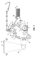
- Figure 1 is a schematic elevational view depicting an electrophotographic printing machine incorporating the features of the present invention;
- Figure 2 is a schematic elevational view depicting a portion of another electrophotographic printing machine using an intermediate transfer belt;
- Figure 3A is an enlarged schematic, fragmentary, perspective view of a roller used in Figure 1 and Figure 2;
- Figure 3B is a further enlarged view of one fragment of the roller as designated in Figure 3A;
- Figure 4A is an enlarged side schematic elevational view of another embodiment of the
- Figure 3A roller;
- Figure 4B is an enlarged front schematic elevational view of the Figure 4A roller;
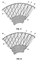
- Figure 5 is an enlarged schematic, sectional, elevational view of a portion of another embodiment of the Figure 3A roller; and
- Figure 6 is an enlarged schematic, sectional, elevational view of a portion of another embodiment of the Figure 3A roller.
- In Figure 1, printing machine 1 employs
belt 2 having a photoconductive surface deposited on a conductive substrate. Initially,belt 2 passes through charging station A. At charging station A, a corona generating device 7 charges the photoconductive surface ofbelt 2 to a relatively high, substantially uniform potential. - After the photoconductive surface of
belt 2 is charged, the charged portion is advanced to exposure station B. At exposure station B, anoriginal document 8 is placed upon atransparent support platen 9. An illumination assembly, indicated generally by thereference numeral 10, illuminates theoriginal document 8 onplaten 9 to produce image rays corresponding to the document information areas. The image rays are projected by means of an optical system onto the charged portion of the photoconductive surface. The light image dissipates the charge in selected areas to record an electrostatic latent image on the photoconductive surface corresponding to the original document informational areas. - After the electrostatic latent image has been recorded,
belt 2 advances the electrostatic latent image to development station C. At development station C,roller 11, rotating in the direction ofarrow 12, advances aliquid developer material 13 from the chamber ofhousing 14 todevelopment zone 17. Anelectrode 16 positioned before the entrance todevelopment zone 17 is electrically biased to generate an AC field just prior to the entrance todevelopment zone 17 so as to disperse the toner particles substantially uniformly throughout the liquid carrier. The toner particles, disseminated through the liquid carrier, pass by electrophoresis to the electrostatic latent image. The charge of the toner particles is opposite in polarity to the charge on the photoconductive surface. - By way of example, the insulating liquid carrier may be a hydrocarbon liquid although other insulating liquids may also be employed. A suitable hydrocarbon liquid is an lsopar which is a trademark of the Exxon Corporation. There is an increased tendency to use liquid carriers such as mineral oil whose structural properties are less volatile, and thereby emit a lower amount of vapor into the atmosphere, consequently emitting fewer harmful and offensive odors. The toner particles comprise a binder and a pigment. The pigment may be carbon black. However, one skilled in the art will appreciate that any suitable liquid development material may be employed.
- Development station C includes
porous roller 18 having perforations (shown in Figures 3 through 6) through the roller skin covering.Roller 18 receives the developed image onbelt 2 and conditions the image by reducing fluid content while inhibiting the departure of toner particles from the image. An increase in percent solids is thereby provided to the developed image, thereby improving the quality of the developed image.Porous roller 18 will be described hereinafter with reference to Figure 2, and in detail with reference to Figures 3 - 6.Porous roller 18 operates in conjunction withvacuum 19 for removal of liquid from the roller. A roller (not shown), in pressure against the blotter roller, may be used in conjunction with or in the place of the vacuum, to squeeze the absorbed liquid carrier from the blotter roller for deposit into a receptacle A blotter roller of the type having a pressure roller for removal of liquid from the blotter roller is described in, for example, copending continuing application for U.S. patent, Serial Number 08/082,141, having a common assignee as the present application, the relevant portions of which are hereby incorporated herein by reference. Abias voltage 53 is applied to an electroconductive roller creating an electric field having the same sign polarity as the toner particles, thereby repelling the toner particles and inhibiting their entry into theroller 18. It will be understood that variations to the blotter roller of the present invention, such as a resistive foam layer found therein (described in further detail with reference to Figure 3A), or a pressure roller used thereagainst, may accompany the blotter roller in conjunction with the photoconductive belt, and/or in conjunction with the intermediate transfer belt as will be described with reference to Figure 2. Furthermore, the present invention may also find useful application where the liquid absorbing roller is in the form of a belt rotated by two or more internal rollers, whereby excess liquid carrier is absorbed through a foam layer and a skin covering having perforations formed therethrough. A belt used for collecting excess liquid from a region of liquid developed images is described in US-A-4,299,902 and 4,258,115, the relevant portions of which are hereby incorporated by reference herein. - In operation,
roller 18 rotates indirection 20 to impose against the "wet" image onbelt 2. The porous body ofroller 18 absorbs excess liquid from the surface of the image through the skin covering pores and perforations.Vacuum 19 located on one end of the central cavity of the roller, draws liquid that has permeated throughroller 18 out through the cavity and deposits the liquid in a receptacle or some other location which will allow for either disposal or recirculation of the liquid carrier.Porous roller 18, discharged of excess liquid, continues to rotate indirection 20 to provide a continuous absorption of liquid from image onbelt 2. - After the electrostatic latent image is developed,
belt 2 advances the developed image to transfer station D At transfer station D, a sheet ofsupport material 22 is advanced fromstack 23 by a sheet transport mechanism, indicated generally by thereference numeral 24. Transfer station D includes acorona generating device 25 which sprays ions onto the backside of the sheet ofsupport material 22. This attracts the developed image from the photoconductive surface ofbelt 2 to copysheet 22. After transfer,conveyor belt 26 moves thecopy sheet 22 to fusing station E. - Fusing station E includes a fuser assembly indicated generally by the
reference numeral 27, which permanently fuses the developed image to thecopy sheet 22.Fuser assembly 27 includes aheated fuser roll 28 and back-uppressure roll 29 resiliently urged into engagement with one another to form a nip through which thecopy sheet 22 passes. After fusing, thefinished copy sheet 22 is discharged tooutput tray 30 for removal by the machine operator. - After the developed image is transferred to copy
sheet 22, residual liquid developer material remains adhering to the photoconductive surface ofbelt 2. A cleaningroller 31 formed of any appropriate synthetic resin, is driven in a direction opposite to the direction of movement ofbelt 2 to scrub the photoconductive surface clean. It is understood, however, that a number of photoconductor cleaning means exist in the art, any of which would be suitable for use with the present invention. Any residual charge left on the photoconductive surface is extinguished by flooding the photoconductive surface with light fromlamps 34. - Figure 2 is a schematic representation of a portion of another printing machine which employs a moving image carrying belt, from which an image is transferred to an intermediate belt. Electrostatographic reproduction apparatus utilizing intermediate belts are described, for example, in US-A-4,183,658; 4,684,238; 4,690,539; and 5,119,140. In Figure 2, elements that are identical to elements in Figure 1 are identified with like reference numerals. Referring to Figure 2, there is shown a printing
machine employing belt 2 having a photoconductive surface deposited on a conductive substrate.Roller 3 rotates and advancesbelt 2 in the direction ofarrow 6.Belt 2 passes through charging station A where a corona generating device 7 charges the photoconductive surface of thebelt 2. The charge portion ofbelt 2 is advanced to exposure station B where image rays from an original document are projected by means of an optical system onto the charged portion of the photoconductive surface to record an electrostatic latent image. After the electrostatic latent image has been recorded,belt 2 advances to development station C. At station C,roller 11 advances aliquid developer material 13 from the chamber ofhousing 14 todevelopment zone 17.Electrode 16 positioned before the entrance todevelopment zone 17 is electrically biased so as to disperse the toner particles substantially uniformly throughout the liquid carrier. Development station C includesporous blotter roller 18 having perforations through the skin surface.Roller 18 receives the developed image onbelt 2 and conditions the image by reducing fluid content while inhibiting the departure of toner particles from the image. The percent solids in the image is thereby increased Theroller 18 operates in conjunction withvacuum 19 for removal of the liquid carrier. A bias voltage is applied to roller 1850 that a repelling force is present to prevent toner particles from leaving the photoconductive surface and entering theroller 18. - After the electrostatic latent image is developed,
belt 2 advances the developed image to transfer station D. At transfer station D, the developed liquid image is electrostatically transferred to an intermediate member or belt indicated generally by thereference numeral 35.Belt 35 is entrained about spacedrollers Belt 35 moves in the direction ofarrow 38.Bias transfer roller 39 imposesbelt 35 againstbelt 2 to assure image transfer to theintermediate belt 35. Theporous blotter roller 40, having perforations through the roller skin covering, receives the developed image onbelt 35 and reduces fluid content while preventing toner particles from departing from the image, so that percent solids of the image is further increased. Theroller 40 increases percent solids to about 25 to 75 wt.% by removing excess liquid carrier in this region. Increasing solids on the intermediate belt is a particularly important function in a color image developing process utilizing multiple superimposed images of different colors. As illustrated in Figure 2, the roller of the present invention may be used for absorbing liquid carrier at an increased rate from an image in a system having an intermediate transfer belt. Consequently, the percent particles on the image is increased, thereby increasing process speed for color imagery. - In operation,
roller 40 rotates indirection 41 to impose against the image onbelt 35. The porous body ofroller 40 absorbs liquid from the surface of the image. The absorbed liquid permeates throughroller 40 and into the innerhollow cavity 49, where a vacuum draws the liquid from theroller 40 into a liquid receptacle or some other location which will allow for either disposal or recirculation of the liquid carrier.Porous roller 40, discharged of excess liquid, continues to rotate indirection 41 to provide a continuous absorption of liquid from images ontransfer belt 35. Abias voltage 53 is applied to the roller to establish a repelling force against the toner particles so that toner particles are prevented from entering theroller 40.Roller 40 may be used in conjunction with a pressure roller (not shown) to remove the liquid that has been absorbed into theroller 40. -
Belt 35 then advances the developed image to transfer station D. At transfer station D, a sheet ofsupport material 22 is advanced fromstack 23 by a sheet transport mechanism, indicated generally by thereference numeral 24. The developed image from the photoconductive surface ofbelt 35 is attracted to copysheet 22. After transfer, conveyor belt 45 moves thecopy sheet 22 to thedischarge output tray 30. - Although the apparatus shown in Figure 2 shows only a single
porous roller 40, multiple porous roller stations can be utilized in accordance with the present invention in conjunction with the transfer of multiple images tointermediate belt 35. - With reference to Figures 3, 4, 5 and 6, there is shown detailed structures of different embodiments of the
porous blotter roller 18 of development station C of Figures 1 and 2, and theporous blotter roller 40 ofintermediate belt 35 of Figure 2. These rollers, with reference to Figures 3 through 6, are collectively referred to by thereference numeral 50, and identical elements associated withroller 50 are identified with like reference numerals. - With reference to Figures 3A and 3B,
roller 50 comprises a rigid poroussupportive core 46. In this embodiment, thecore 46 is in the form of a tube, having ahollow cavity 49 throughout the length of the roller. Aconformable microporous roller 47, and a skin covering 48 having a pattern of apertures orperforations 52 therethrough is provided around thecore 46. Avacuum 19 draws the liquid carrier that has permeated throughroller 50 intocavity 49. A highvoltage bias supply 53 is connected between thebelt 2 and theconductive core 46 ofroller 50 for providing a bias with the same charge as that of the toner particles. The bias continuously repels the toner particles of the image on belt from the roller, while the liquid carrier is absorbed into theroller 50. A pressure controller (not shown) may be used in association with the roller to provide a positive or negative pressure to the roller. - The porous
supportive core 46 can comprise a material selected from the group consisting of sintered metal, plastic and ceramic. In the instance thesupportive core 46 comprises a sintered metal, exemplary metals include stainless steel, copper and bronze. Preferably the material is electroconductive, either by itself, or in combination with another conductive material, so that abias 53 can be applied thereto, and an electrical field will result in a repelling force against the toner particles in the image. For example, the pores of the supportive core generally may be of a diameter of 2,500 microns or less. - The conformable
microporous foam roller 47 is characterized by open cells forming the layer. Theconformable foam roller 47 may comprise an absorbent polymeric and elastomeric material with incorporated conductive filler or dissipative filler. Theconformable roller 47 is characterized by a durometer of from 10 to 90 Shore A, preferably from 20 to 60 Shore A, and has a thickness of 1.0 mils to 500 mils, preferably, a thickness of about 40 mils to 250 mils. The absorption material of themicroporous roller 47 may be any suitable material, preferably a foam such as one selected from the group consisting of Polyurethane, Silicone, Fluorocarbon, Polyimide, Melamine, and rubber, such as Permair@ (a microporous polyurethane material available from Porvair Ltd., England), and Tetratex@ (a microporous semipermeable fluorocarbon membrane available from Tetratec Corp., Pennsylvania). Preferably the absorbent material is resistive so that the electric field created by thebias 53 applied to the core 46 further enhances the repelling action of the toner particles from theroller 50. A suitable level of resistivity of the absorbent material is in the range of 10-5 to 10-11 ohm-cm, and is preferably in the range of 10-6 to 10-9 ohm-cm. The absorbent material must, of course, be compatible with whatever liquid carrier material is used. - The open cell pores of the absorbent material generally may be less than 1,000 microns in diameter, and preferably should be in the range of about 5 to about 300 microns, although the end product may use pore sizes outside these limits. For example, very small pores of a micron or less may be used to absorb liquid carrier from an image, however, an increased pressure would then be required to extract an equivalent amount of liquid as that of a roller having larger size pores.
- The
vacuum system 19 assists in drawing liquid carrier through the blotter roller and into thecavity 49, where it is then removed to a collection location. The vacuum system pressure must be adjusted so as to remove only liquid carrier from the image, and not have so strong a suction force so as to also remove the toner. A vacuum pressure of 1.27cms (0.5 inches) of water to greater than 114cms (45 inches) of water, and preferably within the range of 2.54cms (1.0 inch) to about 38cms (15 inches) of water, has been found to be suitable to the present application. - The vacuum pressure and the speed of the
roller 50 may in one preferred embodiment be selected to keep the pores of roller filled with liquid carrier. It will be appreciated that theperforations 52 formed through the blotter roller skin covering 48 of the present invention increase the rate of absorption of the liquid carrier, and therefore, the overall process speed of the image forming process, particularly when coupled with an increase in vacuum pressure. For example, a blotter roller having an absorbent foam layer made from an Endur-C polyurethane foam from the Roger's Corporation, and having a non-perforated skin covering, showed an increase in permeability of over 85 times, when the skin covering was uniformly laser perforated with holes having an average diameter of 250 microns. - In a preferred embodiment of the present invention, the skin covering 48 has a smooth, glossy surface texture with micropores which are generally of a smaller size than the toner particles of the liquid developer. A minimal surface area texture of the skin covering is preferred so that toner particles are not encouraged to leave the developed image and embed into larger sized pores and/or the irregularities of a rougher skin surface having a greater surface area texture.
- The skin covering 48 has
perforations 52 distributed throughout the surface area of thecovering 48. Perforations formed through the skin covering increase the rate of permeability through the roller. As the absorption rate of liquid from liquid developer in prior art blotter rollers has been a barrier to achieving high image quality at high process speeds, the present invention serves to ensure a high quality image formed at an increased process speed, having a minimal amount of liquid and a maximum amount of toner present during transfer of the image to a final copy sheet. - Perforations formed through the blotter roller skin covering 48 may be circular, or may be any other geometrical shape conducive to maximum absorption of liquid carrier. The perforations may be distributed in a uniform or a non-uniform pattern throughout the surface of the skin covering. In one embodiment of the present invention and as illustrated in Figure 3A, the
circular perforations 52 through the blotter roller skin covering 48 average in size less than 25 microns in diameter, and are preferably in the range of about 1 micron to about 15 microns in diameter. The perforations are spaced apart a center to center distance ranging from 0.015 inches to 0.030 inches. It is understood that slight variations to the perforation size and spacings therebetween would provide similar results of increased permeability of the blotter roller, however, these values should not be substantially exceeded, so that the potential for toner particles to enter the blotter roller is not increased. The blotter roller should remain pervious to liquid carrier, yet substantially impervious to toner particles to inhibit the toner particles from departing the image. - The puncturing process employed to form the perforations may be of a mechanical nature, such as by a needle, knife or other sharp tool that would serve to puncture or cut through the skin covering surface. Thermal techniques such as with a laser, or an etching process through photochemical techniques, or a combination of any of the above listed techniques or their equivalents could alternatively be used to achieve the perforations of the present invention.
- An exemplary perforating process is by water jet drilling, whereby pressurized water produces a pattern of perforations through the skin covering. Direct impingement of a jet of water through a patterned template or mold which would then continue to pierce through the skin covering, may be used to accomplish the perforating process. A cylindrical template, constructed of stainless steel, and having an inner and outer shell, may be used to accomplish the perforating process at a decreased manufacturing cost and at a decreased fabrication time. The desired hole pattern is prebur- ned into the stainless steel such that the inner and outer template patterns are aligned with one another. The skin covering to be perforated is sandwiched between the inner and outer cylindrical templates and secured to a device which allows the template assembly to be rotated. The cylindrical assembly is then placed into an existing high pressure water jet system, where a fan jet nozzle is engaged to traverse the template assembly while it is rotating. The nozzle is positioned such that the high pressure fan of water blows through each hole to remove skin covering matching the predetermined hole diameter or pattern on the template. This process eliminates possible charring of outer edges of the perforations by a thermal technique, e.g. laser, and also minimizes skin residue remaining on the surface from a thermal or mechanical perforating process. Minimal residue is desired so that the surface texture of the skin covering is kept smooth, thereby preventing toner particles from departing the image and adhering to a rougher skin surface.
- In systems where the
blotter roller 50 may be compressed during the liquid carrier removal process, as illustrated in Figures 4A and 4B, the geometry of theperforations 52 through the skin covering 48 may be configured of a shape other than circular, so that a maximum amount of liquid may flow through the blotter roller during compression. Compression of the blotter roller may be a useful step for conditioning of the liquid developer image, whereby the rate of absorption is potentially increased, and the toner particles to the image are compacted, thereby reducing the pile height of the image. - In another embodiment of the invention, and as illustrated by the enlarged, sectional view in Figure 5 showing the relative proportional perforation diameters, apertures or
perforations 54 are also formed as a separate process step through the conformablefoam roller layer 47 using the aforementioned perforating processes and their equivalents. The size of the perforations formed through thisfoam layer 47 is not limited by the toner particle size, as is the size of theperforations 52 formed through theskin covering layer 48. For example, in this embodiment, while theskin covering perforations 52 average less than 15 microns in diameter, theperforations 54 formed through the conformable foam layer average 250 to 300 microns in diameter. - In still another embodiment of the invention, and as illustrated by an enlarged sectional view in Figure 6 showing the perforation diameters, the
perforations 56 are formed through theskin covering layer 48 and theconformable foam layer 47 in a single process step using the aforementioned perforating processes and their equivalents. In this embodiment, however, the perforation size through both layers is restricted by the toner particle size, so that toner is blocked from entering the roller. In this embodiment, for example, theperforations 56 through both the skin covering 48 andconformable foam layer 47 average less than 15 microns in diameter.
Claims (10)
Applications Claiming Priority (2)
| Application Number | Priority Date | Filing Date | Title |
|---|---|---|---|
| US247737 | 1994-05-23 | ||
| US08/247,737 US5424813A (en) | 1994-05-23 | 1994-05-23 | Apparatus and method for improved blotter roller permeability |
Publications (2)
| Publication Number | Publication Date |
|---|---|
| EP0684530A1 true EP0684530A1 (en) | 1995-11-29 |
| EP0684530B1 EP0684530B1 (en) | 1999-09-01 |
Family
ID=22936160
Family Applications (1)
| Application Number | Title | Priority Date | Filing Date |
|---|---|---|---|
| EP95303065A Expired - Lifetime EP0684530B1 (en) | 1994-05-23 | 1995-05-04 | Apparatus for conditioning an image formed from a liquid developer |
Country Status (4)
| Country | Link |
|---|---|
| US (1) | US5424813A (en) |
| EP (1) | EP0684530B1 (en) |
| JP (1) | JPH07319291A (en) |
| DE (1) | DE69511763T2 (en) |
Families Citing this family (40)
| Publication number | Priority date | Publication date | Assignee | Title |
|---|---|---|---|---|
| US5689780A (en) * | 1993-01-27 | 1997-11-18 | Toray Industries, Inc. | Electrophotographic color printing apparatus using successively engageable developing units |
| JPH07334870A (en) * | 1994-06-09 | 1995-12-22 | Olympus Optical Co Ltd | Flaw repair device for optical recording medium |
| US5570173A (en) * | 1994-10-31 | 1996-10-29 | Xerox Corporation | Color printer using liquid developer |
| JP2970514B2 (en) * | 1995-04-28 | 1999-11-02 | 富士ゼロックス株式会社 | Excess developer removal device |
| US5574547A (en) * | 1995-06-07 | 1996-11-12 | Xerox Corporation | Liquid electrophotographic reproduction machine employing heated carrier liquid |
| US5839037A (en) * | 1995-06-07 | 1998-11-17 | Xerox Corporation | Method for transferring a liquid image |
| US5557378A (en) * | 1995-08-25 | 1996-09-17 | Xerox Corporation | Liquid immersion development machine having a pressure differential nip apparatus |
| US5571463A (en) * | 1996-02-09 | 1996-11-05 | Xerox Corporation | Method of fabricating a microporous surface blotter roll |
| JPH09244425A (en) * | 1996-03-13 | 1997-09-19 | Mitsubishi Heavy Ind Ltd | Device and method for image forming |
| US5752144A (en) * | 1996-04-01 | 1998-05-12 | Xerox Corporation | Method of fabricating a reclaimable uniform conditioning blotter roll |
| US5717985A (en) * | 1996-09-27 | 1998-02-10 | Xerox Corporation | Sintered metal fiber core blotter roll and method of making same |
| US5745826A (en) * | 1997-01-21 | 1998-04-28 | Xerox Corporation | Liquid toner image conditioning roll having image protection surface layer |
| KR100234324B1 (en) * | 1997-08-27 | 1999-12-15 | 윤종용 | Wet electrophotographic printer |
| JPH1173023A (en) * | 1997-08-29 | 1999-03-16 | Brother Ind Ltd | Image forming device |
| US6006059A (en) * | 1997-09-08 | 1999-12-21 | Xerox Corporation | Function-separated vacuum-assisted blotter for liquid development image conditioning |
| US5974292A (en) * | 1997-10-31 | 1999-10-26 | Xerox Corporation | Liquid ink development dragout control |
| US6068372A (en) * | 1997-10-31 | 2000-05-30 | Xerox Corporation | Replaceable intermediate transfer surface application assembly |
| US5895147A (en) * | 1997-11-19 | 1999-04-20 | Xerox Corporation | Roll charger with semi-permeable membrane for liquid charging |
| US5895148A (en) * | 1997-11-19 | 1999-04-20 | Xerox Corporation | Control of fluid carrier resistance and water concentration in an aquatron charging device |
| US6073684A (en) | 1998-02-23 | 2000-06-13 | Applied Thermal Technology | Clad casting for laptop computers and the like |
| JP2000075667A (en) * | 1998-08-28 | 2000-03-14 | Brother Ind Ltd | Image forming device |
| JP2000112246A (en) * | 1998-09-30 | 2000-04-21 | Toshiba Corp | Image forming device |
| US6274042B1 (en) * | 1998-10-29 | 2001-08-14 | Voith Sulzer Papiertechnik Gmbh | Semipermeable membrane for pressing apparatus |
| US6357350B1 (en) * | 2000-02-29 | 2002-03-19 | Eastman Kodak Company | Aluminum foam core vacuum imaging drum and method of drum fabrication |
| US6810227B2 (en) * | 2001-11-27 | 2004-10-26 | Bridgestone Corporation | Foamed elastic member for use in image forming apparatus |
| US7052426B2 (en) | 2002-01-25 | 2006-05-30 | Xerox Corporation | Seamed, conformable belt and method of making |
| AU2003229544A1 (en) * | 2002-05-24 | 2003-12-12 | F. Sperling Aps | A method for testing the interaction between at least one liquid sample and a respective solid sample. |
| US7462146B2 (en) * | 2003-08-29 | 2008-12-09 | Canon Kabushiki Kaisha | Roller member, and process for its manufacture |
| JP2006143471A (en) * | 2004-10-18 | 2006-06-08 | Hokushin Ind Inc | Paper feeding roller |
| JP2006349761A (en) * | 2005-06-13 | 2006-12-28 | Toshiba Corp | Electrophotographic device |
| US7316605B1 (en) * | 2006-07-03 | 2008-01-08 | San Fang Chemical Industry Co., Ltd. | Sheet for mounting polishing workpiece and method for making the same |
| US7789738B2 (en) * | 2006-07-03 | 2010-09-07 | San Fang Chemical Industry Co., Ltd. | Sheet for mounting polishing workpiece and method for making the same |
| US20080064310A1 (en) * | 2006-09-08 | 2008-03-13 | Chung-Chih Feng | Polishing pad having hollow fibers and the method for making the same |
| US20090252876A1 (en) * | 2007-05-07 | 2009-10-08 | San Fang Chemical Industry Co., Ltd. | Sheet for mounting polishing workpiece and method for making the same |
| DE102010000549A1 (en) * | 2010-02-25 | 2011-08-25 | Océ Printing Systems GmbH, 85586 | Apparatus and method for developing potential images formed on an intermediate image carrier in an electrographic printing or copying device |
| US9027540B2 (en) | 2011-01-28 | 2015-05-12 | Copper John Corporation | Bowstring release |
| JP5609724B2 (en) * | 2011-03-16 | 2014-10-22 | コニカミノルタ株式会社 | Wet image forming device |
| JP5786579B2 (en) * | 2011-09-15 | 2015-09-30 | ソニー株式会社 | Structure forming device |
| DE102012103343A1 (en) | 2012-04-17 | 2013-10-17 | Océ Printing Systems GmbH & Co. KG | A method of operating a digital printer by exposing a record carrier to ions and associated digital printers |
| US10145646B2 (en) | 2014-11-13 | 2018-12-04 | Scott Archery Llc | Archery bowstring release enabling sensitivity adjustment |
Citations (3)
| Publication number | Priority date | Publication date | Assignee | Title |
|---|---|---|---|---|
| US4237592A (en) * | 1977-06-10 | 1980-12-09 | Canon Kabushiki Kaisha | Elastic roller for image forming apparatus |
| GB2049488A (en) * | 1979-05-15 | 1980-12-31 | Savin Corp | Method and apparatus for removing excess developing liquid from photoconductive surfaces |
| EP0513820A2 (en) * | 1991-05-17 | 1992-11-19 | Hewlett-Packard Company | Conditioning roller and method of operation for use with a photoconductive drum in an electrophotographic color printer |
Family Cites Families (12)
| Publication number | Priority date | Publication date | Assignee | Title |
|---|---|---|---|---|
| US3694071A (en) * | 1969-11-12 | 1972-09-26 | Plastic Coating Corp | Apparatus for prewetting photoelectrostatic offset masters |
| US3955533A (en) * | 1972-09-27 | 1976-05-11 | Smith Ian E | Squeegee roller system for removing excess developer liquid from photoconductive surfaces |
| DE2645672B2 (en) * | 1976-10-09 | 1978-07-27 | Hoechst Ag, 6000 Frankfurt | Apparatus for developing electrophotographic recording materials |
| JPS5424643A (en) * | 1977-07-26 | 1979-02-24 | Canon Inc | Method and apparatus for liquid developing |
| US4258115A (en) * | 1978-03-07 | 1981-03-24 | Canon Kabushiki Kaisha | Wet developing method using elastic roller for electrostatic image and a device therefor |
| US4263391A (en) * | 1978-08-31 | 1981-04-21 | Canon Kabushiki Kaisha | Liquid development process with porous elastic development cleaning roller |
| US4392742A (en) * | 1978-11-09 | 1983-07-12 | Savin Corporation | Liquid developer copier cleaning system incorporating resilient closed-cell cleaning roller |
| US4339858A (en) * | 1980-11-03 | 1982-07-20 | Minnesota Mining And Manufacturing Company | Dampener roll cover |
| NL8304099A (en) * | 1983-11-30 | 1985-06-17 | Oce Nederland Bv | CONTACT FIXING DEVICE. |
| US4985733A (en) * | 1988-04-02 | 1991-01-15 | Ricoh Company, Ltd. | Image fixing unit for use in wet-type electrophotographic copying machine |
| US5028964A (en) * | 1989-02-06 | 1991-07-02 | Spectrum Sciences B.V. | Imaging system with rigidizer and intermediate transfer member |
| US5481341A (en) * | 1993-08-18 | 1996-01-02 | Xerox Corporation | Roller for controlling application of carrier liquid |
-
1994
- 1994-05-23 US US08/247,737 patent/US5424813A/en not_active Expired - Fee Related
-
1995
- 1995-05-04 EP EP95303065A patent/EP0684530B1/en not_active Expired - Lifetime
- 1995-05-04 DE DE69511763T patent/DE69511763T2/en not_active Expired - Fee Related
- 1995-05-15 JP JP7116115A patent/JPH07319291A/en not_active Withdrawn
Patent Citations (3)
| Publication number | Priority date | Publication date | Assignee | Title |
|---|---|---|---|---|
| US4237592A (en) * | 1977-06-10 | 1980-12-09 | Canon Kabushiki Kaisha | Elastic roller for image forming apparatus |
| GB2049488A (en) * | 1979-05-15 | 1980-12-31 | Savin Corp | Method and apparatus for removing excess developing liquid from photoconductive surfaces |
| EP0513820A2 (en) * | 1991-05-17 | 1992-11-19 | Hewlett-Packard Company | Conditioning roller and method of operation for use with a photoconductive drum in an electrophotographic color printer |
Also Published As
| Publication number | Publication date |
|---|---|
| DE69511763T2 (en) | 2000-03-09 |
| US5424813A (en) | 1995-06-13 |
| EP0684530B1 (en) | 1999-09-01 |
| DE69511763D1 (en) | 1999-10-07 |
| JPH07319291A (en) | 1995-12-08 |
Similar Documents
| Publication | Publication Date | Title |
|---|---|---|
| EP0684530B1 (en) | Apparatus for conditioning an image formed from a liquid developer | |
| US5493369A (en) | Apparatus and method for improved liquid developer image conditioning | |
| US5332642A (en) | Vacuum assisted dispersant reduction system | |
| US5640655A (en) | Carrier liquid removing apparatus and image reproducing apparatus using the same | |
| CA1144821A (en) | Method and apparatus for liquid-developing latent electrostatic images | |
| EP0091780B1 (en) | Development apparatus of latent electrostatic images | |
| EP0462172B1 (en) | Electrostatic separator | |
| US5481341A (en) | Roller for controlling application of carrier liquid | |
| US5978630A (en) | System for cleaning contaminants from a vacuum assisted image conditioning roll | |
| DE19744347A1 (en) | Recycling for printed sheet | |
| US5758237A (en) | System for enhancing vacuum efficiency, particularly for conditioning liquid images in a liquid developing material-based electrostatographic system | |
| US5352558A (en) | Toner dispersant absorption belt system | |
| DE2263903A1 (en) | METHOD AND DEVICE FOR ELECTROPHOTOGRAPHY | |
| CA1178643A (en) | Process and apparatus for transferring developed electrostatic images to a carrier sheet, improved carrier sheet for use in the process and method of making the same | |
| JPH1067132A (en) | Liquid ink conditioning system in liquid ink type electrostatic recording system | |
| US5873014A (en) | System for purging contaminants from a vacuum assisted image conditioning roll | |
| EP1241533A2 (en) | Improved transfer roller device | |
| CA1156879A (en) | Method and apparatus for developing latent electrostatic images | |
| US4089683A (en) | Liquid developer cleaning means | |
| US6006059A (en) | Function-separated vacuum-assisted blotter for liquid development image conditioning | |
| US5571463A (en) | Method of fabricating a microporous surface blotter roll | |
| JPS63200176A (en) | Liquid image fixing/liquid carrier removing apparatus | |
| US4478924A (en) | Process for transferring a pigment image using a spacer | |
| US6941103B2 (en) | Release agent management system with anilox roller | |
| US6775502B1 (en) | System and method for high solids image conditioning of liquid ink images utilizing a source of high fluid pressure to configured to emit a jet of fluid |
Legal Events
| Date | Code | Title | Description |
|---|---|---|---|
| PUAI | Public reference made under article 153(3) epc to a published international application that has entered the european phase |
Free format text: ORIGINAL CODE: 0009012 |
|
| AK | Designated contracting states |
Kind code of ref document: A1 Designated state(s): DE FR GB |
|
| 17P | Request for examination filed |
Effective date: 19960529 |
|
| 17Q | First examination report despatched |
Effective date: 19980305 |
|
| GRAG | Despatch of communication of intention to grant |
Free format text: ORIGINAL CODE: EPIDOS AGRA |
|
| GRAG | Despatch of communication of intention to grant |
Free format text: ORIGINAL CODE: EPIDOS AGRA |
|
| GRAH | Despatch of communication of intention to grant a patent |
Free format text: ORIGINAL CODE: EPIDOS IGRA |
|
| GRAH | Despatch of communication of intention to grant a patent |
Free format text: ORIGINAL CODE: EPIDOS IGRA |
|
| GRAA | (expected) grant |
Free format text: ORIGINAL CODE: 0009210 |
|
| AK | Designated contracting states |
Kind code of ref document: B1 Designated state(s): DE FR GB |
|
| REF | Corresponds to: |
Ref document number: 69511763 Country of ref document: DE Date of ref document: 19991007 |
|
| ET | Fr: translation filed | ||
| PLBE | No opposition filed within time limit |
Free format text: ORIGINAL CODE: 0009261 |
|
| STAA | Information on the status of an ep patent application or granted ep patent |
Free format text: STATUS: NO OPPOSITION FILED WITHIN TIME LIMIT |
|
| 26N | No opposition filed | ||
| PGFP | Annual fee paid to national office [announced via postgrant information from national office to epo] |
Ref country code: DE Payment date: 20010430 Year of fee payment: 7 |
|
| PGFP | Annual fee paid to national office [announced via postgrant information from national office to epo] |
Ref country code: GB Payment date: 20010502 Year of fee payment: 7 |
|
| PGFP | Annual fee paid to national office [announced via postgrant information from national office to epo] |
Ref country code: FR Payment date: 20010518 Year of fee payment: 7 |
|
| REG | Reference to a national code |
Ref country code: GB Ref legal event code: IF02 |
|
| PG25 | Lapsed in a contracting state [announced via postgrant information from national office to epo] |
Ref country code: GB Free format text: LAPSE BECAUSE OF NON-PAYMENT OF DUE FEES Effective date: 20020504 |
|
| PG25 | Lapsed in a contracting state [announced via postgrant information from national office to epo] |
Ref country code: DE Free format text: LAPSE BECAUSE OF NON-PAYMENT OF DUE FEES Effective date: 20021203 |
|
| GBPC | Gb: european patent ceased through non-payment of renewal fee |
Effective date: 20020504 |
|
| PG25 | Lapsed in a contracting state [announced via postgrant information from national office to epo] |
Ref country code: FR Free format text: LAPSE BECAUSE OF NON-PAYMENT OF DUE FEES Effective date: 20030131 |
|
| REG | Reference to a national code |
Ref country code: FR Ref legal event code: ST |