EP0684411B1 - Antipolishing ring - Google Patents
Antipolishing ring Download PDFInfo
- Publication number
- EP0684411B1 EP0684411B1 EP19950303511 EP95303511A EP0684411B1 EP 0684411 B1 EP0684411 B1 EP 0684411B1 EP 19950303511 EP19950303511 EP 19950303511 EP 95303511 A EP95303511 A EP 95303511A EP 0684411 B1 EP0684411 B1 EP 0684411B1
- Authority
- EP
- European Patent Office
- Prior art keywords
- antipolishing
- antipolishing ring
- piston
- ring
- ring according
- Prior art date
- Legal status (The legal status is an assumption and is not a legal conclusion. Google has not performed a legal analysis and makes no representation as to the accuracy of the status listed.)
- Expired - Lifetime
Links
- OKTJSMMVPCPJKN-UHFFFAOYSA-N Carbon Chemical compound [C] OKTJSMMVPCPJKN-UHFFFAOYSA-N 0.000 claims abstract description 11
- 229910052799 carbon Inorganic materials 0.000 claims abstract description 7
- 230000000694 effects Effects 0.000 claims description 8
- 239000000463 material Substances 0.000 claims description 4
- 229910052751 metal Inorganic materials 0.000 claims description 4
- 239000002184 metal Substances 0.000 claims description 4
- 229910001374 Invar Inorganic materials 0.000 claims description 3
- 229910000831 Steel Inorganic materials 0.000 claims description 3
- 239000004411 aluminium Substances 0.000 claims description 3
- 229910052782 aluminium Inorganic materials 0.000 claims description 3
- XAGFODPZIPBFFR-UHFFFAOYSA-N aluminium Chemical compound [Al] XAGFODPZIPBFFR-UHFFFAOYSA-N 0.000 claims description 3
- 239000011796 hollow space material Substances 0.000 claims description 3
- 239000010959 steel Substances 0.000 claims description 3
- 229920000297 Rayon Polymers 0.000 claims description 2
- 229920001971 elastomer Polymers 0.000 claims description 2
- 239000000806 elastomer Substances 0.000 claims description 2
- 239000007788 liquid Substances 0.000 claims description 2
- 229910001092 metal group alloy Inorganic materials 0.000 claims description 2
- 238000012423 maintenance Methods 0.000 description 3
- 229910045601 alloy Inorganic materials 0.000 description 1
- 239000000956 alloy Substances 0.000 description 1
- 239000003245 coal Substances 0.000 description 1
- 150000001875 compounds Chemical class 0.000 description 1
- 238000000151 deposition Methods 0.000 description 1
- 239000004205 dimethyl polysiloxane Substances 0.000 description 1
- 235000013870 dimethyl polysiloxane Nutrition 0.000 description 1
- 239000000835 fiber Substances 0.000 description 1
- 239000003365 glass fiber Substances 0.000 description 1
- 238000012986 modification Methods 0.000 description 1
- 230000004048 modification Effects 0.000 description 1
- CXQXSVUQTKDNFP-UHFFFAOYSA-N octamethyltrisiloxane Chemical compound C[Si](C)(C)O[Si](C)(C)O[Si](C)(C)C CXQXSVUQTKDNFP-UHFFFAOYSA-N 0.000 description 1
- 238000004987 plasma desorption mass spectroscopy Methods 0.000 description 1
- 229920000435 poly(dimethylsiloxane) Polymers 0.000 description 1
- -1 polymethylsiloxane Polymers 0.000 description 1
- 229920001296 polysiloxane Polymers 0.000 description 1
- 229920002379 silicone rubber Polymers 0.000 description 1
- 239000004945 silicone rubber Substances 0.000 description 1
Images



Classifications
-
- F—MECHANICAL ENGINEERING; LIGHTING; HEATING; WEAPONS; BLASTING
- F16—ENGINEERING ELEMENTS AND UNITS; GENERAL MEASURES FOR PRODUCING AND MAINTAINING EFFECTIVE FUNCTIONING OF MACHINES OR INSTALLATIONS; THERMAL INSULATION IN GENERAL
- F16J—PISTONS; CYLINDERS; SEALINGS
- F16J10/00—Engine or like cylinders; Features of hollow, e.g. cylindrical, bodies in general
- F16J10/02—Cylinders designed to receive moving pistons or plungers
- F16J10/04—Running faces; Liners
-
- F—MECHANICAL ENGINEERING; LIGHTING; HEATING; WEAPONS; BLASTING
- F02—COMBUSTION ENGINES; HOT-GAS OR COMBUSTION-PRODUCT ENGINE PLANTS
- F02F—CYLINDERS, PISTONS OR CASINGS, FOR COMBUSTION ENGINES; ARRANGEMENTS OF SEALINGS IN COMBUSTION ENGINES
- F02F1/00—Cylinders; Cylinder heads
-
- F—MECHANICAL ENGINEERING; LIGHTING; HEATING; WEAPONS; BLASTING
- F02—COMBUSTION ENGINES; HOT-GAS OR COMBUSTION-PRODUCT ENGINE PLANTS
- F02F—CYLINDERS, PISTONS OR CASINGS, FOR COMBUSTION ENGINES; ARRANGEMENTS OF SEALINGS IN COMBUSTION ENGINES
- F02F11/00—Arrangements of sealings in combustion engines
- F02F11/005—Arrangements of sealings in combustion engines involving cylinder liners
-
- F—MECHANICAL ENGINEERING; LIGHTING; HEATING; WEAPONS; BLASTING
- F02—COMBUSTION ENGINES; HOT-GAS OR COMBUSTION-PRODUCT ENGINE PLANTS
- F02B—INTERNAL-COMBUSTION PISTON ENGINES; COMBUSTION ENGINES IN GENERAL
- F02B3/00—Engines characterised by air compression and subsequent fuel addition
- F02B3/06—Engines characterised by air compression and subsequent fuel addition with compression ignition
-
- F—MECHANICAL ENGINEERING; LIGHTING; HEATING; WEAPONS; BLASTING
- F02—COMBUSTION ENGINES; HOT-GAS OR COMBUSTION-PRODUCT ENGINE PLANTS
- F02F—CYLINDERS, PISTONS OR CASINGS, FOR COMBUSTION ENGINES; ARRANGEMENTS OF SEALINGS IN COMBUSTION ENGINES
- F02F1/00—Cylinders; Cylinder heads
- F02F2001/006—Cylinders; Cylinder heads having a ring at the inside of a liner or cylinder for preventing the deposit of carbon oil particles, e.g. oil scrapers
Definitions
- the invention relates to an antipolishing ring to be used in a cylinder of a large diesel engine, which is supported to a cylinder liner and the purpose of which is to remove possible carbon deposit and carbon residue from the upper portion of a piston in accordance with the preamble of claim 1.
- An object of the invention is to create a new antipolishing ring solution, by means of which i.a. the abovementioned disadvantage in the known solutions can be eliminated.
- the antipolishing ring with an arrangement, by means of which the lower portion of the antipolishingring can be pressed in the radial direction of the cylinder inwards towards the mantle surface of the upper portion of the piston so that the proportion between the diameters of the lower edge and the upper portion of the antipolishing ring is at its minimum while the engine is running, the antipolishing ring may be dimensioned so that its diameter is of the same size or almost of the same size as the cylinder liner when it is in the normal temperature, i.e. when the engine is not in use. Then the piston can be pulled past the antipolishing ring out from the cylinder, which makes maintenance of the engine more uncomplicated.
- the antipolishing ring is assembled of at least two parts of different material, the thermal expansion of which differ from each other substantially and which are located so that the part, the thermal expansion of which is greater, forms a ring-like element encircling the lower portion of the antipolishing ring and pressing, in the running temperature of the engine, the lower portion of the antipolishing ring towards the piston.
- the antipolishing ring may then be made of so called invar metal alloy, whereby the said element may advantageously be of aluminium, steel or the like metal having a substantially high thermal expansion coefficient.
- the thermal expansion coefficient of aluminium is of its order of magnitude more than 20 times and of steel clearly more than 10 times higher than that of the invar alloy.
- the said element may comprise also two or several separate layers arranged radially one inside the other.
- the element may also comprise several segments or bars, the longitudinal thermal expansion of which causes the desired press effect.
- Said element may also comprise a hollow space, which may be filled with an expanding pressure medium, for instance by gas, liquid of melted metal.
- the said arrangement includes means, for example a set of screws or the like, by means of which the lower portion of the antipolishing ring can be pressed mechanically in the radial direction of the cylinder inwards towards the mantle surface of the piston.
- the screws can be arranged to effect on the antipolishing ring also through a half-viscose elastomer portion or through a plastic portion.
- the said supplementary portions are in practice segments, which together form a pressure portion encircling the antipolishing ring.
- the antipolishing ring comprises a set of pressure elements with hollow inner portion to be filled with a pressure medium and the pressure of which is adjustable by means of the said screws or the like.
- pressure mediums which are heat-resistant, solidifying and keep well their volume in the operation temperatures of the engine.
- the pressure medium may with advantage contain for example one or several silicone compounds, for instance silicone rubber and PDMS (polymethylsiloxane), and suitable filling material, for example glass fibre, carbon fibre or the like.
- FIG. 1 indicates a cylinder of a large diesel engine, inside a cylinder liner 2 of which a piston 3 is arranged to move back and forth.
- the cylinder liner 2 is provided with an antipolishing ring 4, which in the prior art solution of Fig. 1 forms a small step, the purpose of which is to remove carbon deposit and carbon residue possibly depositing at the upper portion of the piston during the operation of the engine.
- the upper portion of the piston 3, correspondingly, has a slightly smaller diameter. Therefore, the piston cannot be removed from the cylinder without first removing the antipolishing ring 4.
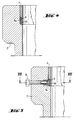
- Figures 2-6 show, correspondingly, different solutions according to the invention, in which the diameter of the upper portion 4a of the antipolishing ring 4 nearly corresponds the inner diameter of the cylinder liner 2, but which comprise an arrangement, by means of which a lower portion 4b of the antipolishing ring 4 may be pressed in the radial direction of the cylinder liner towards the mantle surface of the upper portion of the piston so that a desired effect for removal of carbon deposit and carbon coal is achieved.
- An arrangement according to Fig. 2 is based on a bimetal solution, in which to the lower portion of the antipolishing ring is installed a ring-formed element 5 encircling it and the thermal expansion coefficient of which is substantially higher than of the actual antipolishing ring 4.
- the thermal expansion of the element 5 causes the phenomenon shown in Fig. 2, according to which the lower portion 4b of the antipolishing ring is pressed inwards towards the mantle surface of the upper portion of the piston.
- the element 5 may with advantage be a divided ring or may comprise a set of segments or bar-like members.
- the element 5 comprises a uniform ring, the thermal expansion of which, correspondingly, causes the lower portion 4b of the antipolishing ring to be pressed towards the piston when the engine is in use, whereby the temperature at the same time essentially rises.
- Fig. 3 shows the solution in normal temperature, whereby the engine, thus, is not in use. In this case the element 5 does not prevent pulling the piston out from the cylinder.
- the element 5 comprises a hollow space 5a, which can be filled with some suitable pressure medium for achieving and further increasing the aforementioned pressing effect.
- Fig. 5 for its part comprises a pressing element 7 with a hollow inner space 7a, which can be filled up with a pressure medium and communicating with outer space, whereby the pressure of the inner space 7a and, thus, the pressure effect to be provided can be controlled by means of a screw 6.
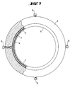
- the elements 7 may advantageously be segments each being provided with an adjusting screw 6 of its own. This is illustrated by Fig. 7, which is a partial section of Fig. 5 and where the pressing element 7 includes four separate segments.
- the solution of Fig. 6 comprises an element 8 mechanically pressable by means of the screw 6. Also in this case the elements 8 are advantageously segments.
Landscapes
- Engineering & Computer Science (AREA)
- General Engineering & Computer Science (AREA)
- Chemical & Material Sciences (AREA)
- Combustion & Propulsion (AREA)
- Mechanical Engineering (AREA)
- Pistons, Piston Rings, And Cylinders (AREA)
- Rotary Switch, Piano Key Switch, And Lever Switch (AREA)
- Arrangement Or Mounting Of Control Devices For Change-Speed Gearing (AREA)
- Saccharide Compounds (AREA)
- Acyclic And Carbocyclic Compounds In Medicinal Compositions (AREA)
- Cylinder Crankcases Of Internal Combustion Engines (AREA)
Abstract
Description
- Fig. 1 shows a prior art solution for an antipolishing ring in section,
- Figures 2-6 show different embodiments of an antipolishing ring according to the invention in section.
- Fig. 7 is partial section VII-VII of Fig. 5.
Claims (9)
- An antipolishing ring (4) to be used in a cylinder (1) of a large diesel engine, which is supported to a cylinder liner (2) for the purpose of removing possible carbon deposit and carbon residue from the upper portion of a piston (3), characterized in that the antipolishing ring (4) is provided with an arrangement, by means of which the lower portion (4b) of the antipolishing ring can be pressed in the radial direction of the cylinder inwards towards the mantle surface of the upper portion of the piston so that the proportion between the diameters of the lower edge (4b) and the upper portion (4a) of the antipolishing ring is at its minimum while the engine is running.
- An antipolishing ring according to claim 1, characterized in that it is assembled of at least two parts (4;5) of different material, the thermal expansion of which differ from each other substantially and which are located so that the part, the thermal expansion of which is greater, forms a ring-like element (5) encircling the lower portion (4b) of the anti-polishingring and pressing, in the running temperature of the engine, the lower portion (4b) of the antipolishing ring towards the piston.
- An antipolishing ring according to claim 2, characterized in that it is made of so called invar metal alloy and the said element (5) is of aluminium, steel or the like metal having a substantially high thermal expansion coefficient.
- An antipolishing ring according to claim 2 or 3, characterized in that the said element comprises several segments or bars, the longitudinal thermal expansion of which causes the desired press effect.
- An antipolishing ring according to claim 2 or 3, characterized in that the said element (5) comprises two or several separate layers arranged radially one inside the other.
- An antipolishing ring according to claim 2, characterized in that the said element (5) comprises a hollow space (5a), which can be filled with an expanding pressure medium, for instance gas, liquid or melted metal.
- An antipolishing ring according to claim 1, characterized in that the said arrangement includes means, for example a set of screws (6) or the like, by means of which the lower portion (4b) of the antipolishing ring can be pressed mechanically in the radial direction of the cylinder inwards towards the mantle surface of the piston.
- An antipolishing ring according to claim 7, characterized in that the screws (6) are arranged to effect on the antipolishing ring (4) through a half-viscose elastomer portion or through a plastic portion (8).
- An antipolishing ring according to claim 7, characterized in that it includes a set of pressure elements (7) with hollow inner portion (7a) to be filled with a pressure medium and the pressure of which being adjustable by means of the said screws (6) or the like.
Applications Claiming Priority (2)
| Application Number | Priority Date | Filing Date | Title |
|---|---|---|---|
| FI942498 | 1994-05-27 | ||
| FI942498A FI95830C (en) | 1994-05-27 | 1994-05-27 | antipolishingring |
Publications (2)
| Publication Number | Publication Date |
|---|---|
| EP0684411A1 EP0684411A1 (en) | 1995-11-29 |
| EP0684411B1 true EP0684411B1 (en) | 1998-09-16 |
Family
ID=8540792
Family Applications (1)
| Application Number | Title | Priority Date | Filing Date |
|---|---|---|---|
| EP19950303511 Expired - Lifetime EP0684411B1 (en) | 1994-05-27 | 1995-05-25 | Antipolishing ring |
Country Status (5)
| Country | Link |
|---|---|
| US (1) | US5553585A (en) |
| EP (1) | EP0684411B1 (en) |
| AT (1) | ATE171254T1 (en) |
| DE (1) | DE69504752T2 (en) |
| FI (1) | FI95830C (en) |
Families Citing this family (29)
| Publication number | Priority date | Publication date | Assignee | Title |
|---|---|---|---|---|
| FR2763362A1 (en) * | 1997-05-13 | 1998-11-20 | Semt Pielstick | DEVICE FOR SCRAPING THE HEAD OF A PISTON |
| DE19917707C2 (en) * | 1999-04-20 | 2001-03-01 | Daimler Chrysler Ag | Internal combustion engine with a crankcase |
| FI106972B (en) * | 1999-06-04 | 2001-05-15 | Waertsilae Tech Oy Ab | Coke Ironing Call Events |
| US6234134B1 (en) | 2000-06-20 | 2001-05-22 | General Electric Company | Internal combustion engine having integral anti-polishing ring |
| US6314937B1 (en) | 2000-06-20 | 2001-11-13 | General Electric Company | Internal combustion engine and method for controlling the production of oxides of nitrogen |
| JPWO2005045222A1 (en) * | 2003-10-16 | 2008-03-06 | 株式会社リケン | Internal combustion engine and liner mounting ring |
| US7438039B2 (en) * | 2004-02-06 | 2008-10-21 | Electro-Motive Diesel, Inc. | Large-bore, medium-speed diesel engine having piston crown bowl with acute re-entrant angle |
| US7438038B2 (en) * | 2006-04-24 | 2008-10-21 | Federal-Mogul Worldwide, Inc. | Cylinder liner and methods construction thereof and improving engine performance therewith |
| SE534911C2 (en) * | 2010-06-16 | 2012-02-14 | Scania Cv Ab | Arrangements in an internal combustion engine |
| EP2535540B1 (en) | 2011-06-16 | 2016-07-20 | Wärtsilä Switzerland Ltd. | Insert for a cylinder of a combustion engine |
| US9562491B2 (en) * | 2012-04-20 | 2017-02-07 | International Engine Intellectual Property Company, Llc. | Carbon scraping ring with abradable coating |
| EP3114338B1 (en) * | 2014-03-03 | 2021-04-28 | Cummins, Inc. | Carbon scraper |
| US20160053709A1 (en) | 2014-08-19 | 2016-02-25 | Caterpillar Inc. | Cylinder liner assembly having thermal barrier |
| US20160097340A1 (en) * | 2014-10-03 | 2016-04-07 | Caterpillar Inc. | Cylinder liner assembly having air gap insulation |
| DE102014115042A1 (en) * | 2014-10-16 | 2016-04-21 | Obrist Technologies Gmbh | generator |
| US9845764B2 (en) * | 2015-03-31 | 2017-12-19 | Achates Power, Inc. | Cylinder liner for an opposed-piston engine |
| US9657682B2 (en) | 2015-06-02 | 2017-05-23 | Caterpillar Inc. | Cylinder liner assembly having a thermal barrier coating |
| US10156202B2 (en) | 2016-03-04 | 2018-12-18 | Achates Power, Inc. | Barrier ring and assembly for a cylinder of an opposed-piston engine |
| EP3423693B1 (en) * | 2016-03-04 | 2021-02-17 | Wärtsilä Finland Oy | Cylinder liner and anti-polishing ring |
| CN109312695B (en) * | 2016-06-01 | 2020-09-08 | 瓦锡兰芬兰有限公司 | Method and piston engine for reducing hydrocarbon emissions |
| US10487779B2 (en) * | 2017-03-20 | 2019-11-26 | International Engine Intellectual Property Company, Llc. | Piston scraping ring with power groove |
| EP3724479B1 (en) | 2017-12-14 | 2026-04-22 | Cummins Inc. | Antipolishing ring |
| EP3540202A1 (en) | 2018-03-14 | 2019-09-18 | Winterthur Gas & Diesel Ltd. | Sealing ring, cylinder for a combustion engine, combustion engine, method for producing a cylinder and use of a sealing ring |
| CN109869239A (en) * | 2019-04-15 | 2019-06-11 | 一汽解放汽车有限公司 | A kind of engine piston |
| WO2021126509A1 (en) * | 2019-12-17 | 2021-06-24 | Cummins Inc. | Compound diameter carbon scraper ring |
| US11280291B2 (en) | 2019-12-31 | 2022-03-22 | Mahle International Gmbh | Cylinder liner with temperature sensor |
| EP4143463A1 (en) | 2020-04-30 | 2023-03-08 | Wärtsilä Finland Oy | An antipolishing ring |
| WO2021242565A1 (en) | 2020-05-27 | 2021-12-02 | Cummins Inc. | Anti-polish ring for an engine cylinder |
| US20260110271A1 (en) * | 2024-10-23 | 2026-04-23 | Innio Jenbacher Gmbh & Co Og | System and method having an anti-polishing ring for a piston |
Family Cites Families (10)
| Publication number | Priority date | Publication date | Assignee | Title |
|---|---|---|---|---|
| US3620137A (en) * | 1969-10-06 | 1971-11-16 | Ramsey Corp | Piston sleeve |
| DE3038235C2 (en) * | 1980-10-10 | 1983-12-22 | Mahle Gmbh, 7000 Stuttgart | Cylinder or cylinder liner for reciprocating internal combustion engines |
| DE3123080A1 (en) * | 1981-06-11 | 1982-08-26 | Daimler-Benz Ag, 7000 Stuttgart | Cylinder liner for a reciprocating piston engine, especially an internal combustion engine |
| US4474147A (en) * | 1981-12-10 | 1984-10-02 | Mack Trucks, Inc. | Combined fire ring and carbon scraping insert |
| JPS60243349A (en) * | 1984-05-18 | 1985-12-03 | Mitsui Eng & Shipbuild Co Ltd | Cylinder liner |
| DE3543668A1 (en) * | 1985-12-11 | 1987-06-19 | Man Nutzfahrzeuge Gmbh | CYLINDER BUSHING FOR PISTON COMBUSTION ENGINES |
| US5058488A (en) * | 1988-10-26 | 1991-10-22 | Metal Leve S.A. | Means for preventing the build-up of carbon deposits on pistons |
| JPH02241952A (en) * | 1989-03-13 | 1990-09-26 | Mazda Motor Corp | Cylinder block of engine |
| JPH041453A (en) * | 1990-04-16 | 1992-01-06 | Mitsubishi Heavy Ind Ltd | Cylinder liner |
| US5112066A (en) * | 1990-12-05 | 1992-05-12 | Arne Remmerfelt | Resilient sealing ring |
-
1994
- 1994-05-27 FI FI942498A patent/FI95830C/en active
-
1995
- 1995-05-16 US US08/441,934 patent/US5553585A/en not_active Expired - Fee Related
- 1995-05-25 DE DE69504752T patent/DE69504752T2/en not_active Expired - Fee Related
- 1995-05-25 EP EP19950303511 patent/EP0684411B1/en not_active Expired - Lifetime
- 1995-05-25 AT AT95303511T patent/ATE171254T1/en not_active IP Right Cessation
Also Published As
| Publication number | Publication date |
|---|---|
| FI942498A0 (en) | 1994-05-27 |
| FI95830C (en) | 1996-03-25 |
| EP0684411A1 (en) | 1995-11-29 |
| DE69504752D1 (en) | 1998-10-22 |
| ATE171254T1 (en) | 1998-10-15 |
| US5553585A (en) | 1996-09-10 |
| FI95830B (en) | 1995-12-15 |
| DE69504752T2 (en) | 1999-05-27 |
Similar Documents
| Publication | Publication Date | Title |
|---|---|---|
| US5553585A (en) | Anti-polishing ring | |
| IE61689B1 (en) | A composite material cartridge for use in a device for making monocrystals | |
| EP0217262B1 (en) | End cap for a ceramic spool and apparatus for mounting it | |
| EP1867411A3 (en) | Casting of molten metal in an open ended mold cavity | |
| JPS5553587A (en) | Transcription material | |
| US4385715A (en) | Rotary sliding closure unit and liquid melt container employing the same | |
| GB2110772A (en) | Bearing assembly | |
| CA2202525A1 (en) | Process for isolating mesophase pitch | |
| US20050204796A1 (en) | Press oven including an intermediate body, and method for use | |
| US7210901B2 (en) | Assembly of sectors of a dispensing unit in a gas turbine | |
| US5269988A (en) | Electrolyte holder | |
| AU705055B2 (en) | Tundish stopper rod for continuous casting | |
| JPH0259165A (en) | Anti-gravity casting equipment | |
| US4060692A (en) | Induction melting furnace | |
| GR3000542T3 (en) | Casting roll and method for overhauling it | |
| EP0152726A1 (en) | Pressure vessel for high-pressure apparatus | |
| US4097208A (en) | Ultrahigh pressure apparatus for diamond synthesis | |
| US5184665A (en) | Interconnecting device for casting molded parts | |
| GB2103349A (en) | Combustion chamber | |
| PL298421A1 (en) | Low temperature carbonization apparatus | |
| US4516480A (en) | Piston ring for endothermic motors having an improved flame damper ring | |
| SU1119775A1 (en) | Isostat | |
| US1648149A (en) | Method of forming refractory crucibles | |
| KR100387878B1 (en) | A device for controlling the flow of plastics material, heated until flowable, through a housing | |
| PL318684A1 (en) | Casting roll of a continuous casting installation for casting metals on a single roll or between two rolls |
Legal Events
| Date | Code | Title | Description |
|---|---|---|---|
| PUAI | Public reference made under article 153(3) epc to a published international application that has entered the european phase |
Free format text: ORIGINAL CODE: 0009012 |
|
| AK | Designated contracting states |
Kind code of ref document: A1 Designated state(s): AT CH DE FR GB LI NL |
|
| 17P | Request for examination filed |
Effective date: 19960409 |
|
| GRAG | Despatch of communication of intention to grant |
Free format text: ORIGINAL CODE: EPIDOS AGRA |
|
| 17Q | First examination report despatched |
Effective date: 19971128 |
|
| GRAG | Despatch of communication of intention to grant |
Free format text: ORIGINAL CODE: EPIDOS AGRA |
|
| GRAH | Despatch of communication of intention to grant a patent |
Free format text: ORIGINAL CODE: EPIDOS IGRA |
|
| RAP1 | Party data changed (applicant data changed or rights of an application transferred) |
Owner name: WAERTSILAE NSD OY AB |
|
| GRAH | Despatch of communication of intention to grant a patent |
Free format text: ORIGINAL CODE: EPIDOS IGRA |
|
| GRAA | (expected) grant |
Free format text: ORIGINAL CODE: 0009210 |
|
| AK | Designated contracting states |
Kind code of ref document: B1 Designated state(s): AT CH DE FR GB LI NL |
|
| REF | Corresponds to: |
Ref document number: 171254 Country of ref document: AT Date of ref document: 19981015 Kind code of ref document: T |
|
| REG | Reference to a national code |
Ref country code: CH Ref legal event code: EP |
|
| REF | Corresponds to: |
Ref document number: 69504752 Country of ref document: DE Date of ref document: 19981022 |
|
| REG | Reference to a national code |
Ref country code: CH Ref legal event code: NV Representative=s name: A. BRAUN, BRAUN, HERITIER, ESCHMANN AG PATENTANWAE |
|
| ET | Fr: translation filed | ||
| PLBE | No opposition filed within time limit |
Free format text: ORIGINAL CODE: 0009261 |
|
| STAA | Information on the status of an ep patent application or granted ep patent |
Free format text: STATUS: NO OPPOSITION FILED WITHIN TIME LIMIT |
|
| 26N | No opposition filed | ||
| PGFP | Annual fee paid to national office [announced via postgrant information from national office to epo] |
Ref country code: AT Payment date: 20010410 Year of fee payment: 7 |
|
| PGFP | Annual fee paid to national office [announced via postgrant information from national office to epo] |
Ref country code: FR Payment date: 20010411 Year of fee payment: 7 |
|
| PGFP | Annual fee paid to national office [announced via postgrant information from national office to epo] |
Ref country code: GB Payment date: 20010419 Year of fee payment: 7 |
|
| PGFP | Annual fee paid to national office [announced via postgrant information from national office to epo] |
Ref country code: DE Payment date: 20010423 Year of fee payment: 7 Ref country code: CH Payment date: 20010423 Year of fee payment: 7 |
|
| PGFP | Annual fee paid to national office [announced via postgrant information from national office to epo] |
Ref country code: NL Payment date: 20010424 Year of fee payment: 7 |
|
| REG | Reference to a national code |
Ref country code: GB Ref legal event code: IF02 |
|
| PG25 | Lapsed in a contracting state [announced via postgrant information from national office to epo] |
Ref country code: GB Free format text: LAPSE BECAUSE OF NON-PAYMENT OF DUE FEES Effective date: 20020525 Ref country code: AT Free format text: LAPSE BECAUSE OF NON-PAYMENT OF DUE FEES Effective date: 20020525 |
|
| PG25 | Lapsed in a contracting state [announced via postgrant information from national office to epo] |
Ref country code: LI Free format text: LAPSE BECAUSE OF NON-PAYMENT OF DUE FEES Effective date: 20020531 Ref country code: CH Free format text: LAPSE BECAUSE OF NON-PAYMENT OF DUE FEES Effective date: 20020531 |
|
| PG25 | Lapsed in a contracting state [announced via postgrant information from national office to epo] |
Ref country code: NL Free format text: LAPSE BECAUSE OF NON-PAYMENT OF DUE FEES Effective date: 20021201 |
|
| PG25 | Lapsed in a contracting state [announced via postgrant information from national office to epo] |
Ref country code: DE Free format text: LAPSE BECAUSE OF NON-PAYMENT OF DUE FEES Effective date: 20021203 |
|
| GBPC | Gb: european patent ceased through non-payment of renewal fee |
Effective date: 20020525 |
|
| REG | Reference to a national code |
Ref country code: CH Ref legal event code: PL |
|
| PG25 | Lapsed in a contracting state [announced via postgrant information from national office to epo] |
Ref country code: FR Free format text: LAPSE BECAUSE OF NON-PAYMENT OF DUE FEES Effective date: 20030131 |
|
| NLV4 | Nl: lapsed or anulled due to non-payment of the annual fee |
Effective date: 20021201 |
|
| REG | Reference to a national code |
Ref country code: FR Ref legal event code: ST |