EP0684007B1 - Domestic drainage container - Google Patents
Domestic drainage container Download PDFInfo
- Publication number
- EP0684007B1 EP0684007B1 EP95106945A EP95106945A EP0684007B1 EP 0684007 B1 EP0684007 B1 EP 0684007B1 EP 95106945 A EP95106945 A EP 95106945A EP 95106945 A EP95106945 A EP 95106945A EP 0684007 B1 EP0684007 B1 EP 0684007B1
- Authority
- EP
- European Patent Office
- Prior art keywords
- chamber
- partition
- wall
- receptacle
- container according
- Prior art date
- Legal status (The legal status is an assumption and is not a legal conclusion. Google has not performed a legal analysis and makes no representation as to the accuracy of the status listed.)
- Expired - Lifetime
Links
Images



Classifications
-
- A—HUMAN NECESSITIES
- A47—FURNITURE; DOMESTIC ARTICLES OR APPLIANCES; COFFEE MILLS; SPICE MILLS; SUCTION CLEANERS IN GENERAL
- A47J—KITCHEN EQUIPMENT; COFFEE MILLS; SPICE MILLS; APPARATUS FOR MAKING BEVERAGES
- A47J47/00—Kitchen containers, stands or the like, not provided for in other groups of this subclass; Cutting-boards, e.g. for bread
- A47J47/18—Pails for kitchen use
-
- Y—GENERAL TAGGING OF NEW TECHNOLOGICAL DEVELOPMENTS; GENERAL TAGGING OF CROSS-SECTIONAL TECHNOLOGIES SPANNING OVER SEVERAL SECTIONS OF THE IPC; TECHNICAL SUBJECTS COVERED BY FORMER USPC CROSS-REFERENCE ART COLLECTIONS [XRACs] AND DIGESTS
- Y10—TECHNICAL SUBJECTS COVERED BY FORMER USPC
- Y10S—TECHNICAL SUBJECTS COVERED BY FORMER USPC CROSS-REFERENCE ART COLLECTIONS [XRACs] AND DIGESTS
- Y10S206/00—Special receptacle or package
- Y10S206/804—Special receptacle or package with means to lift or draw out content
Definitions
- the invention broadly relates to the storage of hand-held scrubbing implements such as normally used with water and/or other cleaning liquids both in and around the kitchen sinks, laundry tubs, bathroom fixtures, and the like.
- Such implements can include scrubbing brushes, bottle brushes, sponges, scouring pads, etc.
- such implements are normally stored while still wet or damp.
- the wet implements will be left in the sink, on an adjacent drainage board, or in a cabinet beneath the sink, preferably within a bucket.
- the implement sits within a wet pool as the liquid drains therefrom. This is not only undesirable because the drying process is extended, but also is not particularly sanitary and could be a potential health hazard.
- EP-A-0254507 discloses an apparatus for insertion into a bucket for maintaining a portion of cleaning liquid therein free of suspended solids.
- a platform is provided in spaced relation to the bottom of the bucket, and side walls help to substantially separate solids which have settled below the platform.
- a mop may then be soaked in the cleaning fluid without picking up any suspended solids by inserting the mop into the bucket insert.
- a drainage container for hand-held scrubbing implements said container including a receptacle and a partition, said receptacle comprising a base and an upwardly extending wall sealed to and surrounding said base and forming an upwardly opening chamber, said wall having an upper rim portion defining an upwardly opening chamber mouth remote from said base, said partition comprising a support platform removably positioned in said chamber in overlying relation to said base for the support of implements received through said chamber mouth, spacer means for supporting said platform in closely spaced relation above said base in said chamber, drainage means for allowing drainage downwardly past said platform to said base, handle means engaged with said platform and extending upwardly through said chamber and beyond said chamber mouth to define a handle for said container, cooperating retainer means on said wall and on said partition for releasably fixing said partition within said chamber, said retainer means comprising a projection on said wall extending inwardly relative to said chamber, and a cooperating portion on said partition underlying said wall projection
- the present invention thus provides a drainage container or bucket for compactly storing wet-scrubbing implements in a convenient manner wherein provision is made for the liquid to drain away from the implements, thus accelerating the drying of the implements and achieving the various advantages to be derived therefrom.
- the drainage container includes an open topped receptacle with a removable partition therein.
- the partition includes an apertured support platform positioned within the receptacle in spaced relation above the base for the elevated support of the various implements in a manner which allows liquid to drain downwardly away from the implements to a separate subjacent area.
- the platform is provided with a panel extending transversely across the platform, bisecting the interior of the receptacle and projecting upwardly therefrom beyond the open mouth of the receptacle to define a handle.
- the upper portion of the panel includes an aperture therethrough to provide a convenient grip means for a user's hand.
- the opposed side edges of the handle panel are provided with upwardly directed shoulders. These shoulders engage beneath an inner peripheral flange of a rim element or member which snap locks to the rim of the receptacle.
- the flange projects slightly inward of the inner face of the receptacle wall completely thereabout and acts to engage the panel shoulders and preclude withdrawal of the partition from the receptacle. In this manner, the entire drainage container, either with or without the implements received therein, can be picked up and moved to a stored position, for example under the sink.
- the handle panel has multiple functions, including acting as a means for carrying the entire container, as a means for separating the support platform from the container, and as a means for dividing the receptacle chamber in two compartments for maintaining a separation of stored items as might be desired.
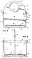
- the sink container, or drainage container is generally designated by reference numeral 10 and comprises three preformed components, a receptacle 12, a rim element or member 14, and a partition 16.
- the components are each made of an appropriate synthetic resinous material, with the receptacle and partition preferably being rigid or of minimal flexibility, and with the rim member 14 having a sufficient degree of resilient flexibility as to enable a releasable snap-locking to the receptacle as shall be explained subsequently.
- the receptacle 12 includes a base or bottom 18, preferably slightly inwardly convex for stable positioning on a support surface.
- An upwardly extending wall 20 is integrally formed with the outer periphery of the base 18, normally with an arcuate transition corner area 22 therebetween, and terminates in an upper rim portion 24 which defines an open receptacle mouth remote from the base.
- the receptacle 12 defines an upwardly opening chamber 26 which receives the partition 16.
- the inner surface 28 of the receptacle wall may flare slightly upwardly from the base to the rim portion to facilitate introduction of the partition 16. This inner surface is smooth and uninterrupted upwardly from the base 18 to the rim portion 24.
- the inner configuration of the wall 20 includes a snap-lock retaining component having an inwardly extending and downwardly directed shoulder 30 with a beveled inner face 32 extending from the shoulder 30 to the extreme upper edge 34 of the receptacle wall 20.
- This snap-lock component 30, 32 is integrally defined with the wall 20 and extends peripherally thereabout.
- the rim element or member 14 includes a depending inner flange 36 and an integral laterally outwardly directed upper flange 38 terminating in an outer gripping bead 39. Both flanges are continuous and respectively dimensioned whereby the downwardly directed inner flange 36 lies against the inner face of the rim portion 24 of the receptacle 12, and the upper or outer flange 38 seats on the upper edge 34 of the receptacle wall 20.
- the inner rim member flange 36 is specifically adapted to releasably snap lock to the rim portion 24 of the receptacle.
- this flange is undercut, immediately adjacent to and for a distance downward of the upper flange 38 to define an upwardly directed shoulder 40 which, noting Figures 7 and 8, snap locks beneath the rim portion shoulder 30.
- These shoulders may taper slightly upward and inward relative to the interior of the receptacle to facilitate disengagement.
- the height of the undercut which defines the rim member shoulder 40 is such as to engage the undersurface 42 of the outer flange 38 on the upper edge 34 of the receptacle wall 20 when the snap lock components 30 and 40 are engaged.
- the beveled inner surface 32 of the rim portion 24 of the receptacle facilitates engagement of the rim member 14 in an obvious manner.
- the lower flat edge 44 of the inner depending flange 36 defines a downwardly directed shoulder or abutment extending laterally inward from the inner surface 28 of the receptacle wall. The significance of this abutment 44 will be described subsequently.
- the partition 16 comprises a support platform 46 which is positioned within the receptacle chamber 26 in overlying substantially parallel relation to the base 18 and supported in spaced relation thereabove by elongate spacer members 48 integral with the platform 46 and depending from the undersurface thereof generally parallel to and slightly inwardly spaced from the outer periphery or peripheral edge 50 of the platform 46. As illustrated, two such spacer members 48 may be provided with the opposed ends thereof spaced from each other at opposed areas of the platform 46.
- the partition 16 further includes an upwardly extending handle panel 52 transversely across the platform 46 centrally thereof so as to in effect bisect the platform and the receptacle chamber 26.
- the handle panel is substantially planar and, at the joinder with the support platform, is of a transverse length equal to or substantially equal to the transverse dimension of the support platform 46.
- the opposed upwardly directed side edges 54 of the panel 52 substantially parallel the opposed portions of the inner surface 28 of the receptacle wall 20. That is, if the inner surface 28 is slightly upwardly tapered, the side edges 54 will preferably also be so tapered.
- the outer peripheral edge 50 of the support platform 46, as well as the opposed upwardly directed side edges 54 of the handle panel 52, are slightly inwardly spaced from the inner surface 26 of the receptacle wall, providing for free sliding introduction and removal of the partition as well as an annular drainage aperture or space about the platform.
- Additional drainage apertures 56 are provided in spaced relation along an elongate extent paralleling the outer peripheral edge 50 of the platform 46 in inwardly spaced relation thereto. Assuming the platform 46 is circular as illustrated, the drainage apertures 56 will be arranged in a circular ring about the platform 46, or more particularly a pair of semicircular arcs, one to each side of the handle panel.
- the platform 46 outwardly and downwardly slopes from a central area to the outer periphery. This slope will be gradual for a portion thereof between the central area and the area of the drainage apertures 56. Within this area of drainage apertures 56, the slope will increase, for example by 15°, with the drainage apertures 56 at right angles therethrough whereby the desired effective drainage is provided while at the same time, the angle of the apertures to the vertical tends to restrict any tendency for implements introduced in the receptacle inadvertently falling through or jamming within the apertures.
- the sloping surface, outward beyond the apertures 56 returns to a minimal inclination, and in fact the upper surface of the platform 46 may have no inclination beyond the supporting spacer members 48.
- the lower edge of the handle panel 52, at the integral joinder thereof to the platform 46, is slightly widened to provide for a rigid joinder.
- aligned recesses 57 can be provided in the undersurface of the support platform 46 in this area for a reduction of materials without a corresponding weakening of the platform or joinder area.
- this panel projects upwardly through and substantially beyond the open upper mouth of the receptacle 20, terminating in an arcuate upper edge 58.
- the upwardly extending portion of the panel 52 centrally thereof and spaced slightly below the arcuate upper edge 58, is provided with an enlarged transverse aperture 60 therethrough peripherally surrounded by an integral enlarged bead 62 which both strengthens the aperture 60 and provides a comfortable grip for a hand or fingers inserted through the aperture 60 for manually carrying or repositioning the container.
- the handle panel In order to enable use of the handle panel as a means for carrying the receptacle, provision is made for releasably locking the partition 16 within the receptacle 12.
- the upper portions of the opposed side edges 54 of the handle panel 52, at points immediately below the abutment lower edge 44 on the rim member 14, are inwardly offset to define outwardly directed and upwardly facing retaining shoulders 64 upon which the abutment edge 44 engages, thereby providing cooperative retaining means for releasably fixing the partition 16 within the chamber 26 of the receptacle.
- the height or location of the panel shoulders 64 is such as to engage the abutment 44 while the lower spacer or spacers 48 are fully seated on the base 18 of the receptacle 12.
- the transverse length of the handle panel 52, above the opposed shoulders 64, is narrower than below the shoulders 64 so as to extend freely through the rim member 14 and merge into the arcuate upper edge 58.
- the container is assembled with the rim member 14 removed.
- the partition With the support platform lowermost, is slidably introduced into the receptacle chamber through the open mouth thereof.
- the rim member 14 Upon a full seating of the partition within the chamber, the rim member 14 is positioned about the upwardly projecting portion of the handle panel and moved downwardly into snap-locking engagement with the rim portion 24 of the receptacle 12. Such action engages the abutment or abutment edge 44 against the panel shoulders 64 whereby upward withdrawal of the handle panel and partition from the receptacle chamber is precluded.
- the platform is thus retained in position, and the handle panel 52 used as a convenient handle for the entire assembly.
- the rim member 14 can be quickly and easily released for disassembly and cleaning purposes. Release will normally be effected by a gripping of the outer bead 39 of the rim member and upwardly and inwardly flexing the rim member in a manner similar to that used in various types of snap-locked seals for containers.
- the support platform as an integral portion of the handle panel 52, is removed from the receptacle chamber by merely upwardly withdrawing the handle panel.
- receptacle 12 is cylindrical. This in turn defines the configuration of the support platform as circular, and the rim member 14 as annular, all as illustrated. With a circular support platform 46, the drainage apertures 56 will be defined along a single or a pair of opposed arcs. Similarly, the spacing support members 48 will be arcuate. Other receptacle configurations, such as rectangular, are also contemplated, with the partition and rim member configured for accommodation within and to the receptacle.
Landscapes
- Food Science & Technology (AREA)
- Engineering & Computer Science (AREA)
- Details Of Rigid Or Semi-Rigid Containers (AREA)
- Table Devices Or Equipment (AREA)
- Thermally Insulated Containers For Foods (AREA)
- Cookers (AREA)
- Food-Manufacturing Devices (AREA)
- Non-Flushing Toilets (AREA)
- Packaging Of Machine Parts And Wound Products (AREA)
- Packaging Of Annular Or Rod-Shaped Articles, Wearing Apparel, Cassettes, Or The Like (AREA)
- Packages (AREA)
- Sink And Installation For Waste Water (AREA)
- Cleaning By Liquid Or Steam (AREA)
Abstract
Description
Claims (12)
- A drainage container (10) for hand-held scrubbing implements, said container including a receptacle (12) and a partition (16), said receptacle (12) comprising a base (18) and an upwardly extending wall (20) sealed to and surrounding said base (18)and forming an upwardly opening chamber (26), said wall (20) having an upper rim portion (24) defining an upwardly opening chamber mouth remote from said base (18), said partition (16) comprising a support platform (46) removably positioned in said chamber (26) in overlying relation to said base (18) for the support of implements received through said chamber mouth, spacer means (48) for supporting said platform (46) in closely spaced relation above said base (18) in said chamber (26), drainage means for allowing drainage downwardly past said platform (46)to said base (18), handle means engaged with said platform (46) and extending upwardly through said chamber (26) and beyond said chamber mouth to define a handle for said container (10), cooperating retainer means on said wall (20) and on said partition (16) for releasably fixing said partition (16) within said chamber (26), said retainer means comprising a projection on said wall (20)extending inwardly relative to said chamber (26), and a cooperating portion on said partition (16) underlying said wall projection adapted to be retained thereby, and means for disengaging said wall projection and said partition portion, said partition (16) being removable from said chamber (26) upon release of said retainer means.
- A container according to claim 1, wherein said cooperating portion on said partition comprises a laterally extending shoulder (64) upwardly directed toward said chamber mouth, said wall projection being mounted on said wall (20) over said shoulder (64) to preclude withdrawal of said partition (16) from said receptacle chamber (26), said means for disengaging said wall projection and said partition portion providing for withdrawal of said wall projection from said shoulder (64).
- A container according to claim 2, wherein said means for disengaging comprises a rim member (14) releasably secured to said rim portion (24) of said wall (20) , said rim member (14) extending laterally inward of said wall (20) into said chamber (26) to define said wall projection (32), wherein removal of said rim member (14) disengages said projection from said partition shoulder.
- A container according to claim 3, wherein said rim member (14) is substantially coextensive with said rim portion (24), means for releasably snap-locking said rim member (14) to said rim portion (24), said rim member (14) including an inner flange (36) within said wall (20), said inner flange (36) forming a portion of the rim member (14) which defines said wall projection.
- A container according to any one of claims 2 to 4, including a second laterally (64) extending shoulder on said partition (16) remote from said first-mentioned partition shoulder (64) and upwardly directed toward said chamber mouth, said wall projection overlying said second shoulder (64).
- A container according to claim 5, wherein said handle means comprises a panel (52) having opposed side edges (54) positioned closely adjacent opposed portions of said wall (20), said first-mentioned and second shoulders (64) being on said side edges (54) respectively and immediately below said rim member flange (36), wherein upward movement of said partition (16) is precluded until removal of said rim member (14).
- A container according to any preceding claim, wherein said handle means, beyond said chamber mouth, includes means for manual gripping of the handle means and raising of said receptacle (12).
- A container according to any preceding claim, wherein said support platform (46) generally parallels said base (18) and has an outer periphery (50)in closely spaced relation to said wall (20) peripherally about said chamber (26) to allow restricted drainage therebetween and to define said means for allowing drainage, said support platform (46) including an upper surface sloping outwardly to define a slope generally from a central area thereto toward said outer periphery (50).
- A container according to claim 8, wherein said means for allowing drainage further includes multiple apertures (56) defined through said support platform (46) intermediate said central area and said outer periphery (50).
- A container according to any preceding claim, wherein said handle means panel (52) bisects said support platform (46) and divides said chamber (26) into two compartments.
- A container according to claim 9 or 10, wherein said support platform (46) is circular, said multiple apertures (56) being aligned along an arc generally paralleling said outer periphery (50) of said support platform (46).
- A container according to any one of claims 9 to 11, wherein said slope, in that portion of said support platform (46) through which said apertures (56) are defined, are at a substantially greater angle than said slope adjacent said central area and said outer periphery (50), said apertures (56) being at substantially right angles to said slope whereat said apertures (56) are defined.
Applications Claiming Priority (2)
| Application Number | Priority Date | Filing Date | Title |
|---|---|---|---|
| US249601 | 1994-05-27 | ||
| US08/249,601 US5551591A (en) | 1994-05-27 | 1994-05-27 | Sink container |
Publications (2)
| Publication Number | Publication Date |
|---|---|
| EP0684007A1 EP0684007A1 (en) | 1995-11-29 |
| EP0684007B1 true EP0684007B1 (en) | 1998-12-02 |
Family
ID=22944198
Family Applications (1)
| Application Number | Title | Priority Date | Filing Date |
|---|---|---|---|
| EP95106945A Expired - Lifetime EP0684007B1 (en) | 1994-05-27 | 1995-05-08 | Domestic drainage container |
Country Status (14)
| Country | Link |
|---|---|
| US (1) | US5551591A (en) |
| EP (1) | EP0684007B1 (en) |
| JP (1) | JP2553325B2 (en) |
| KR (1) | KR0155209B1 (en) |
| AT (1) | ATE173901T1 (en) |
| AU (1) | AU681012B2 (en) |
| BR (1) | BR9502543A (en) |
| CA (1) | CA2150083C (en) |
| DE (1) | DE69506316T2 (en) |
| DK (1) | DK0684007T3 (en) |
| ES (1) | ES2127431T3 (en) |
| FI (1) | FI952576L (en) |
| IL (1) | IL113597A (en) |
| ZA (1) | ZA953800B (en) |
Families Citing this family (17)
| Publication number | Priority date | Publication date | Assignee | Title |
|---|---|---|---|---|
| DE19635620C2 (en) * | 1996-09-03 | 2002-05-02 | Freudenberg Carl Kg | mop bucket |
| USD402777S (en) | 1997-09-22 | 1998-12-15 | Dart Industries Inc. | Flatware bin |
| ITPD20020189A1 (en) * | 2002-07-12 | 2004-01-12 | Filmop Srl | DEVICES FOR DISENGAGEMENT OF THE DIVIDING WALL REMOVABLE FROM THE COUPLING FOR THE BASINS OR BUCKETS IN WHICH IT IS INSERTED. |
| US20070051647A1 (en) * | 2003-07-29 | 2007-03-08 | Bao Sheng Corporation | Pull-up tray container |
| GB0322157D0 (en) * | 2003-09-22 | 2003-10-22 | Numatic Int Ltd | Bucket for mopping |
| US20070011939A1 (en) * | 2005-07-13 | 2007-01-18 | Shimano American Corporation | Storage systems |
| US9572443B2 (en) * | 2005-09-08 | 2017-02-21 | Mortissa Osborne | Container with utensil holder |
| FR2898801A1 (en) * | 2006-03-23 | 2007-09-28 | Financ Elysees Balzac Sa | BUCKET FOR LIQUID CLEANING PRODUCT |
| USD603659S1 (en) | 2008-07-14 | 2009-11-10 | Dart Industries Inc. | Kitchen utensil holder |
| US8757386B2 (en) * | 2010-09-30 | 2014-06-24 | Abbott Diabetes Care Inc. | Analyte test strip containers and inserts |
| WO2013070664A1 (en) * | 2011-11-09 | 2013-05-16 | Csp Technologies, Inc. | Container with insert |
| US20140284293A1 (en) * | 2013-03-19 | 2014-09-25 | Ginsey Industries, Inc. | Shower Storage Caddy |
| DE102013114234B3 (en) * | 2013-12-17 | 2015-05-28 | Karl Göttler | Edge unit and container unit |
| CN104352208A (en) * | 2014-10-27 | 2015-02-18 | 秦方 | Water ejection and centrifuging washing device of rotating mop |
| CA3036042A1 (en) * | 2018-03-07 | 2019-09-07 | Berry Global, Inc. | Package |
| CN109665194B (en) * | 2018-12-29 | 2020-03-17 | 重庆市永川区佳悦家政服务有限公司 | Portable storage box for household appliances |
| KR102101032B1 (en) * | 2019-01-25 | 2020-04-14 | 창신리빙(주) | Toilet cleaning utensils |
Family Cites Families (12)
| Publication number | Priority date | Publication date | Assignee | Title |
|---|---|---|---|---|
| US1337477A (en) * | 1919-04-22 | 1920-04-20 | Henry F Knapp | Apparatus for washing automobiles and the like |
| US1517164A (en) * | 1922-03-30 | 1924-11-25 | Melchor F Lear | Scrubbing pail |
| US1848331A (en) * | 1930-01-29 | 1932-03-08 | Bertha M Esslinger | Multiple compartment pail |
| US2712668A (en) * | 1951-06-18 | 1955-07-12 | Hazel L Thiele | Scrub bucket |
| US2896809A (en) * | 1956-11-01 | 1959-07-28 | Parke H Metzger | Nesting pail |
| US3070226A (en) * | 1961-01-18 | 1962-12-25 | Norma K Mathison | Container for foodstuffs |
| US3363794A (en) * | 1966-05-27 | 1968-01-16 | William P Aiken | Article lift for containers |
| US3458078A (en) * | 1968-06-06 | 1969-07-29 | Procter & Gamble | Measuring device for packaged products |
| US4179040A (en) * | 1978-08-11 | 1979-12-18 | Dart Industries Inc. | Storage and serving container or the like |
| US4751763A (en) * | 1986-07-17 | 1988-06-21 | E And R Investments | Mop bucket insert |
| US5082135A (en) * | 1990-05-08 | 1992-01-21 | Dart Industries Inc. | Container for storing and dispensing goods |
| US5086917A (en) * | 1991-03-22 | 1992-02-11 | Mobil Oil Corporation | Utility caddy for use with or without a bucket |
-
1994
- 1994-05-27 US US08/249,601 patent/US5551591A/en not_active Expired - Fee Related
-
1995
- 1995-05-03 IL IL113597A patent/IL113597A/en active IP Right Grant
- 1995-05-05 AU AU17876/95A patent/AU681012B2/en not_active Ceased
- 1995-05-08 DK DK95106945T patent/DK0684007T3/en active
- 1995-05-08 EP EP95106945A patent/EP0684007B1/en not_active Expired - Lifetime
- 1995-05-08 DE DE69506316T patent/DE69506316T2/en not_active Expired - Fee Related
- 1995-05-08 ES ES95106945T patent/ES2127431T3/en not_active Expired - Lifetime
- 1995-05-08 AT AT95106945T patent/ATE173901T1/en not_active IP Right Cessation
- 1995-05-10 ZA ZA953800A patent/ZA953800B/en unknown
- 1995-05-24 CA CA002150083A patent/CA2150083C/en not_active Expired - Fee Related
- 1995-05-25 BR BR9502543A patent/BR9502543A/en not_active IP Right Cessation
- 1995-05-26 FI FI952576A patent/FI952576L/en unknown
- 1995-05-26 KR KR1019950013402A patent/KR0155209B1/en not_active Expired - Fee Related
- 1995-05-29 JP JP7130852A patent/JP2553325B2/en not_active Expired - Lifetime
Also Published As
| Publication number | Publication date |
|---|---|
| DE69506316D1 (en) | 1999-01-14 |
| CA2150083C (en) | 2006-01-24 |
| DK0684007T3 (en) | 1999-08-16 |
| ES2127431T3 (en) | 1999-04-16 |
| KR950031802A (en) | 1995-12-20 |
| IL113597A (en) | 1998-03-10 |
| AU681012B2 (en) | 1997-08-14 |
| CA2150083A1 (en) | 1995-11-28 |
| AU1787695A (en) | 1995-12-07 |
| US5551591A (en) | 1996-09-03 |
| FI952576A0 (en) | 1995-05-26 |
| BR9502543A (en) | 1995-12-26 |
| DE69506316T2 (en) | 1999-04-29 |
| JPH082584A (en) | 1996-01-09 |
| ZA953800B (en) | 1996-06-04 |
| IL113597A0 (en) | 1995-08-31 |
| ATE173901T1 (en) | 1998-12-15 |
| KR0155209B1 (en) | 1999-02-18 |
| EP0684007A1 (en) | 1995-11-29 |
| FI952576A7 (en) | 1995-11-28 |
| JP2553325B2 (en) | 1996-11-13 |
| FI952576L (en) | 1995-11-28 |
Similar Documents
| Publication | Publication Date | Title |
|---|---|---|
| US5551591A (en) | Sink container | |
| US7318247B2 (en) | Bucket combination | |
| US9682471B2 (en) | Modular tool holder | |
| US5183280A (en) | Multi-purpose elevated bucket | |
| US5211294A (en) | Tilesetters tray | |
| US3298532A (en) | Device for storing articles | |
| US4024590A (en) | Patient sanitary care unit | |
| US7240910B2 (en) | Receptacle caddy | |
| US7475937B2 (en) | Eating surface with interchangeable accessories | |
| US5927492A (en) | Decorative container for storing plumbing plunger | |
| US20020109318A1 (en) | Janitorial cart | |
| US8696028B2 (en) | Janitorial container with segmented, drainable utility compartments | |
| US20040206761A1 (en) | Handheld container with removable divider | |
| US5605247A (en) | Mat with removable receptacle | |
| AU2010263377A1 (en) | A serving tray with removable handle | |
| US20250277357A1 (en) | Workstation sinks and accessories | |
| US20110163104A1 (en) | Multi-purpose bucket, particularly for painting | |
| US5325962A (en) | Combined lid and tray attachment | |
| US20080135422A1 (en) | Jewelry Holder | |
| US7121415B1 (en) | Utensil receptacle | |
| US20180153350A1 (en) | Portable Campground Sink | |
| US20150001869A1 (en) | Toilet removal and disposal tray | |
| US20080173658A1 (en) | Device for removing dirty shoe covers | |
| US10932624B2 (en) | Sanitation pail with pour and sediment collection features | |
| GB2444635A (en) | Container for kitchen waste |
Legal Events
| Date | Code | Title | Description |
|---|---|---|---|
| PUAI | Public reference made under article 153(3) epc to a published international application that has entered the european phase |
Free format text: ORIGINAL CODE: 0009012 |
|
| AK | Designated contracting states |
Kind code of ref document: A1 Designated state(s): AT BE CH DE DK ES FR GB GR IE IT LI LU MC NL PT SE |
|
| 17P | Request for examination filed |
Effective date: 19960205 |
|
| 17Q | First examination report despatched |
Effective date: 19970116 |
|
| GRAG | Despatch of communication of intention to grant |
Free format text: ORIGINAL CODE: EPIDOS AGRA |
|
| GRAG | Despatch of communication of intention to grant |
Free format text: ORIGINAL CODE: EPIDOS AGRA |
|
| GRAG | Despatch of communication of intention to grant |
Free format text: ORIGINAL CODE: EPIDOS AGRA |
|
| GRAH | Despatch of communication of intention to grant a patent |
Free format text: ORIGINAL CODE: EPIDOS IGRA |
|
| GRAH | Despatch of communication of intention to grant a patent |
Free format text: ORIGINAL CODE: EPIDOS IGRA |
|
| GRAA | (expected) grant |
Free format text: ORIGINAL CODE: 0009210 |
|
| AK | Designated contracting states |
Kind code of ref document: B1 Designated state(s): AT BE CH DE DK ES FR GB GR IE IT LI LU MC NL PT SE |
|
| REF | Corresponds to: |
Ref document number: 173901 Country of ref document: AT Date of ref document: 19981215 Kind code of ref document: T |
|
| REG | Reference to a national code |
Ref country code: CH Ref legal event code: NV Representative=s name: A. BRAUN, BRAUN, HERITIER, ESCHMANN AG PATENTANWAELTE Ref country code: CH Ref legal event code: EP |
|
| REF | Corresponds to: |
Ref document number: 69506316 Country of ref document: DE Date of ref document: 19990114 |
|
| REG | Reference to a national code |
Ref country code: IE Ref legal event code: FG4D |
|
| ITF | It: translation for a ep patent filed | ||
| RAP2 | Party data changed (patent owner data changed or rights of a patent transferred) |
Owner name: DART INDUSTRIES INC. |
|
| ET | Fr: translation filed | ||
| REG | Reference to a national code |
Ref country code: PT Ref legal event code: SC4A Free format text: AVAILABILITY OF NATIONAL TRANSLATION Effective date: 19981204 |
|
| PGFP | Annual fee paid to national office [announced via postgrant information from national office to epo] |
Ref country code: SE Payment date: 19990414 Year of fee payment: 5 |
|
| REG | Reference to a national code |
Ref country code: ES Ref legal event code: FG2A Ref document number: 2127431 Country of ref document: ES Kind code of ref document: T3 |
|
| PGFP | Annual fee paid to national office [announced via postgrant information from national office to epo] |
Ref country code: PT Payment date: 19990422 Year of fee payment: 5 |
|
| NLT2 | Nl: modifications (of names), taken from the european patent patent bulletin |
Owner name: DART INDUSTRIES INC. |
|
| PGFP | Annual fee paid to national office [announced via postgrant information from national office to epo] |
Ref country code: GB Payment date: 19990505 Year of fee payment: 5 |
|
| PGFP | Annual fee paid to national office [announced via postgrant information from national office to epo] |
Ref country code: DE Payment date: 19990507 Year of fee payment: 5 |
|
| PGFP | Annual fee paid to national office [announced via postgrant information from national office to epo] |
Ref country code: FR Payment date: 19990511 Year of fee payment: 5 |
|
| PGFP | Annual fee paid to national office [announced via postgrant information from national office to epo] |
Ref country code: DK Payment date: 19990512 Year of fee payment: 5 Ref country code: AT Payment date: 19990512 Year of fee payment: 5 |
|
| PGFP | Annual fee paid to national office [announced via postgrant information from national office to epo] |
Ref country code: CH Payment date: 19990514 Year of fee payment: 5 |
|
| PGFP | Annual fee paid to national office [announced via postgrant information from national office to epo] |
Ref country code: LU Payment date: 19990518 Year of fee payment: 5 |
|
| PGFP | Annual fee paid to national office [announced via postgrant information from national office to epo] |
Ref country code: GR Payment date: 19990520 Year of fee payment: 5 |
|
| PGFP | Annual fee paid to national office [announced via postgrant information from national office to epo] |
Ref country code: ES Payment date: 19990524 Year of fee payment: 5 |
|
| PGFP | Annual fee paid to national office [announced via postgrant information from national office to epo] |
Ref country code: IE Payment date: 19990528 Year of fee payment: 5 |
|
| PGFP | Annual fee paid to national office [announced via postgrant information from national office to epo] |
Ref country code: NL Payment date: 19990531 Year of fee payment: 5 Ref country code: MC Payment date: 19990531 Year of fee payment: 5 |
|
| PGFP | Annual fee paid to national office [announced via postgrant information from national office to epo] |
Ref country code: BE Payment date: 19990728 Year of fee payment: 5 |
|
| REG | Reference to a national code |
Ref country code: DK Ref legal event code: T3 |
|
| PLBE | No opposition filed within time limit |
Free format text: ORIGINAL CODE: 0009261 |
|
| STAA | Information on the status of an ep patent application or granted ep patent |
Free format text: STATUS: NO OPPOSITION FILED WITHIN TIME LIMIT |
|
| 26N | No opposition filed | ||
| PG25 | Lapsed in a contracting state [announced via postgrant information from national office to epo] |
Ref country code: LU Free format text: LAPSE BECAUSE OF NON-PAYMENT OF DUE FEES Effective date: 20000508 Ref country code: IE Free format text: LAPSE BECAUSE OF NON-PAYMENT OF DUE FEES Effective date: 20000508 Ref country code: GB Free format text: LAPSE BECAUSE OF NON-PAYMENT OF DUE FEES Effective date: 20000508 Ref country code: DK Free format text: LAPSE BECAUSE OF NON-PAYMENT OF DUE FEES Effective date: 20000508 Ref country code: AT Free format text: LAPSE BECAUSE OF NON-PAYMENT OF DUE FEES Effective date: 20000508 |
|
| PG25 | Lapsed in a contracting state [announced via postgrant information from national office to epo] |
Ref country code: SE Free format text: LAPSE BECAUSE OF NON-PAYMENT OF DUE FEES Effective date: 20000509 Ref country code: ES Free format text: THE PATENT HAS BEEN ANNULLED BY A DECISION OF A NATIONAL AUTHORITY Effective date: 20000509 |
|
| PG25 | Lapsed in a contracting state [announced via postgrant information from national office to epo] |
Ref country code: LI Free format text: LAPSE BECAUSE OF NON-PAYMENT OF DUE FEES Effective date: 20000531 Ref country code: GR Free format text: LAPSE BECAUSE OF NON-PAYMENT OF DUE FEES Effective date: 20000531 Ref country code: CH Free format text: LAPSE BECAUSE OF NON-PAYMENT OF DUE FEES Effective date: 20000531 Ref country code: BE Free format text: LAPSE BECAUSE OF NON-PAYMENT OF DUE FEES Effective date: 20000531 |
|
| BERE | Be: lapsed |
Owner name: DART INDUSTRIES INC. Effective date: 20000531 |
|
| PG25 | Lapsed in a contracting state [announced via postgrant information from national office to epo] |
Ref country code: PT Free format text: LAPSE BECAUSE OF NON-PAYMENT OF DUE FEES Effective date: 20001130 Ref country code: MC Free format text: LAPSE BECAUSE OF NON-PAYMENT OF DUE FEES Effective date: 20001130 |
|
| PG25 | Lapsed in a contracting state [announced via postgrant information from national office to epo] |
Ref country code: NL Free format text: LAPSE BECAUSE OF NON-PAYMENT OF DUE FEES Effective date: 20001201 |
|
| GBPC | Gb: european patent ceased through non-payment of renewal fee |
Effective date: 20000508 |
|
| REG | Reference to a national code |
Ref country code: CH Ref legal event code: PL |
|
| EUG | Se: european patent has lapsed |
Ref document number: 95106945.9 |
|
| REG | Reference to a national code |
Ref country code: DK Ref legal event code: EBP |
|
| PG25 | Lapsed in a contracting state [announced via postgrant information from national office to epo] |
Ref country code: FR Free format text: LAPSE BECAUSE OF NON-PAYMENT OF DUE FEES Effective date: 20010131 |
|
| NLV4 | Nl: lapsed or anulled due to non-payment of the annual fee |
Effective date: 20001201 |
|
| PG25 | Lapsed in a contracting state [announced via postgrant information from national office to epo] |
Ref country code: DE Free format text: LAPSE BECAUSE OF NON-PAYMENT OF DUE FEES Effective date: 20010301 |
|
| REG | Reference to a national code |
Ref country code: FR Ref legal event code: ST |
|
| REG | Reference to a national code |
Ref country code: IE Ref legal event code: MM4A |
|
| REG | Reference to a national code |
Ref country code: PT Ref legal event code: MM4A Free format text: LAPSE DUE TO NON-PAYMENT OF FEES Effective date: 20001130 |
|
| REG | Reference to a national code |
Ref country code: ES Ref legal event code: FD2A Effective date: 20020304 |
|
| PG25 | Lapsed in a contracting state [announced via postgrant information from national office to epo] |
Ref country code: IT Free format text: LAPSE BECAUSE OF NON-PAYMENT OF DUE FEES;WARNING: LAPSES OF ITALIAN PATENTS WITH EFFECTIVE DATE BEFORE 2007 MAY HAVE OCCURRED AT ANY TIME BEFORE 2007. THE CORRECT EFFECTIVE DATE MAY BE DIFFERENT FROM THE ONE RECORDED. Effective date: 20050508 |