EP0683790B1 - Automated synthesis of oligonucleotides - Google Patents
Automated synthesis of oligonucleotides Download PDFInfo
- Publication number
- EP0683790B1 EP0683790B1 EP94907420A EP94907420A EP0683790B1 EP 0683790 B1 EP0683790 B1 EP 0683790B1 EP 94907420 A EP94907420 A EP 94907420A EP 94907420 A EP94907420 A EP 94907420A EP 0683790 B1 EP0683790 B1 EP 0683790B1
- Authority
- EP
- European Patent Office
- Prior art keywords
- reaction
- supports
- reagent
- outlet
- support
- Prior art date
- Legal status (The legal status is an assumption and is not a legal conclusion. Google has not performed a legal analysis and makes no representation as to the accuracy of the status listed.)
- Expired - Lifetime
Links
Images



Classifications
-
- B—PERFORMING OPERATIONS; TRANSPORTING
- B01—PHYSICAL OR CHEMICAL PROCESSES OR APPARATUS IN GENERAL
- B01J—CHEMICAL OR PHYSICAL PROCESSES, e.g. CATALYSIS OR COLLOID CHEMISTRY; THEIR RELEVANT APPARATUS
- B01J19/00—Chemical, physical or physico-chemical processes in general; Their relevant apparatus
- B01J19/0046—Sequential or parallel reactions, e.g. for the synthesis of polypeptides or polynucleotides; Apparatus and devices for combinatorial chemistry or for making molecular arrays
-
- B—PERFORMING OPERATIONS; TRANSPORTING
- B01—PHYSICAL OR CHEMICAL PROCESSES OR APPARATUS IN GENERAL
- B01J—CHEMICAL OR PHYSICAL PROCESSES, e.g. CATALYSIS OR COLLOID CHEMISTRY; THEIR RELEVANT APPARATUS
- B01J2219/00—Chemical, physical or physico-chemical processes in general; Their relevant apparatus
- B01J2219/00274—Sequential or parallel reactions; Apparatus and devices for combinatorial chemistry or for making arrays; Chemical library technology
- B01J2219/00277—Apparatus
- B01J2219/00279—Features relating to reactor vessels
- B01J2219/00281—Individual reactor vessels
- B01J2219/00286—Reactor vessels with top and bottom openings
-
- B—PERFORMING OPERATIONS; TRANSPORTING
- B01—PHYSICAL OR CHEMICAL PROCESSES OR APPARATUS IN GENERAL
- B01J—CHEMICAL OR PHYSICAL PROCESSES, e.g. CATALYSIS OR COLLOID CHEMISTRY; THEIR RELEVANT APPARATUS
- B01J2219/00—Chemical, physical or physico-chemical processes in general; Their relevant apparatus
- B01J2219/00274—Sequential or parallel reactions; Apparatus and devices for combinatorial chemistry or for making arrays; Chemical library technology
- B01J2219/00277—Apparatus
- B01J2219/00279—Features relating to reactor vessels
- B01J2219/00306—Reactor vessels in a multiple arrangement
- B01J2219/00308—Reactor vessels in a multiple arrangement interchangeably mounted in racks or blocks
-
- B—PERFORMING OPERATIONS; TRANSPORTING
- B01—PHYSICAL OR CHEMICAL PROCESSES OR APPARATUS IN GENERAL
- B01J—CHEMICAL OR PHYSICAL PROCESSES, e.g. CATALYSIS OR COLLOID CHEMISTRY; THEIR RELEVANT APPARATUS
- B01J2219/00—Chemical, physical or physico-chemical processes in general; Their relevant apparatus
- B01J2219/00274—Sequential or parallel reactions; Apparatus and devices for combinatorial chemistry or for making arrays; Chemical library technology
- B01J2219/00277—Apparatus
- B01J2219/00351—Means for dispensing and evacuation of reagents
- B01J2219/00364—Pipettes
-
- B—PERFORMING OPERATIONS; TRANSPORTING
- B01—PHYSICAL OR CHEMICAL PROCESSES OR APPARATUS IN GENERAL
- B01J—CHEMICAL OR PHYSICAL PROCESSES, e.g. CATALYSIS OR COLLOID CHEMISTRY; THEIR RELEVANT APPARATUS
- B01J2219/00—Chemical, physical or physico-chemical processes in general; Their relevant apparatus
- B01J2219/00274—Sequential or parallel reactions; Apparatus and devices for combinatorial chemistry or for making arrays; Chemical library technology
- B01J2219/00277—Apparatus
- B01J2219/00351—Means for dispensing and evacuation of reagents
- B01J2219/00414—Means for dispensing and evacuation of reagents using suction
- B01J2219/00416—Vacuum
-
- B—PERFORMING OPERATIONS; TRANSPORTING
- B01—PHYSICAL OR CHEMICAL PROCESSES OR APPARATUS IN GENERAL
- B01J—CHEMICAL OR PHYSICAL PROCESSES, e.g. CATALYSIS OR COLLOID CHEMISTRY; THEIR RELEVANT APPARATUS
- B01J2219/00—Chemical, physical or physico-chemical processes in general; Their relevant apparatus
- B01J2219/00274—Sequential or parallel reactions; Apparatus and devices for combinatorial chemistry or for making arrays; Chemical library technology
- B01J2219/00277—Apparatus
- B01J2219/00351—Means for dispensing and evacuation of reagents
- B01J2219/00418—Means for dispensing and evacuation of reagents using pressure
-
- B—PERFORMING OPERATIONS; TRANSPORTING
- B01—PHYSICAL OR CHEMICAL PROCESSES OR APPARATUS IN GENERAL
- B01J—CHEMICAL OR PHYSICAL PROCESSES, e.g. CATALYSIS OR COLLOID CHEMISTRY; THEIR RELEVANT APPARATUS
- B01J2219/00—Chemical, physical or physico-chemical processes in general; Their relevant apparatus
- B01J2219/00274—Sequential or parallel reactions; Apparatus and devices for combinatorial chemistry or for making arrays; Chemical library technology
- B01J2219/00277—Apparatus
- B01J2219/00351—Means for dispensing and evacuation of reagents
- B01J2219/00423—Means for dispensing and evacuation of reagents using filtration, e.g. through porous frits
-
- B—PERFORMING OPERATIONS; TRANSPORTING
- B01—PHYSICAL OR CHEMICAL PROCESSES OR APPARATUS IN GENERAL
- B01J—CHEMICAL OR PHYSICAL PROCESSES, e.g. CATALYSIS OR COLLOID CHEMISTRY; THEIR RELEVANT APPARATUS
- B01J2219/00—Chemical, physical or physico-chemical processes in general; Their relevant apparatus
- B01J2219/00274—Sequential or parallel reactions; Apparatus and devices for combinatorial chemistry or for making arrays; Chemical library technology
- B01J2219/00277—Apparatus
- B01J2219/00497—Features relating to the solid phase supports
- B01J2219/005—Beads
-
- B—PERFORMING OPERATIONS; TRANSPORTING
- B01—PHYSICAL OR CHEMICAL PROCESSES OR APPARATUS IN GENERAL
- B01J—CHEMICAL OR PHYSICAL PROCESSES, e.g. CATALYSIS OR COLLOID CHEMISTRY; THEIR RELEVANT APPARATUS
- B01J2219/00—Chemical, physical or physico-chemical processes in general; Their relevant apparatus
- B01J2219/00274—Sequential or parallel reactions; Apparatus and devices for combinatorial chemistry or for making arrays; Chemical library technology
- B01J2219/00583—Features relative to the processes being carried out
- B01J2219/00585—Parallel processes
-
- B—PERFORMING OPERATIONS; TRANSPORTING
- B01—PHYSICAL OR CHEMICAL PROCESSES OR APPARATUS IN GENERAL
- B01J—CHEMICAL OR PHYSICAL PROCESSES, e.g. CATALYSIS OR COLLOID CHEMISTRY; THEIR RELEVANT APPARATUS
- B01J2219/00—Chemical, physical or physico-chemical processes in general; Their relevant apparatus
- B01J2219/00274—Sequential or parallel reactions; Apparatus and devices for combinatorial chemistry or for making arrays; Chemical library technology
- B01J2219/00583—Features relative to the processes being carried out
- B01J2219/0059—Sequential processes
-
- B—PERFORMING OPERATIONS; TRANSPORTING
- B01—PHYSICAL OR CHEMICAL PROCESSES OR APPARATUS IN GENERAL
- B01J—CHEMICAL OR PHYSICAL PROCESSES, e.g. CATALYSIS OR COLLOID CHEMISTRY; THEIR RELEVANT APPARATUS
- B01J2219/00—Chemical, physical or physico-chemical processes in general; Their relevant apparatus
- B01J2219/00274—Sequential or parallel reactions; Apparatus and devices for combinatorial chemistry or for making arrays; Chemical library technology
- B01J2219/00583—Features relative to the processes being carried out
- B01J2219/00596—Solid-phase processes
-
- B—PERFORMING OPERATIONS; TRANSPORTING
- B01—PHYSICAL OR CHEMICAL PROCESSES OR APPARATUS IN GENERAL
- B01J—CHEMICAL OR PHYSICAL PROCESSES, e.g. CATALYSIS OR COLLOID CHEMISTRY; THEIR RELEVANT APPARATUS
- B01J2219/00—Chemical, physical or physico-chemical processes in general; Their relevant apparatus
- B01J2219/00274—Sequential or parallel reactions; Apparatus and devices for combinatorial chemistry or for making arrays; Chemical library technology
- B01J2219/0068—Means for controlling the apparatus of the process
- B01J2219/00686—Automatic
- B01J2219/00689—Automatic using computers
-
- B—PERFORMING OPERATIONS; TRANSPORTING
- B01—PHYSICAL OR CHEMICAL PROCESSES OR APPARATUS IN GENERAL
- B01J—CHEMICAL OR PHYSICAL PROCESSES, e.g. CATALYSIS OR COLLOID CHEMISTRY; THEIR RELEVANT APPARATUS
- B01J2219/00—Chemical, physical or physico-chemical processes in general; Their relevant apparatus
- B01J2219/00274—Sequential or parallel reactions; Apparatus and devices for combinatorial chemistry or for making arrays; Chemical library technology
- B01J2219/0068—Means for controlling the apparatus of the process
- B01J2219/00695—Synthesis control routines, e.g. using computer programs
-
- B—PERFORMING OPERATIONS; TRANSPORTING
- B01—PHYSICAL OR CHEMICAL PROCESSES OR APPARATUS IN GENERAL
- B01J—CHEMICAL OR PHYSICAL PROCESSES, e.g. CATALYSIS OR COLLOID CHEMISTRY; THEIR RELEVANT APPARATUS
- B01J2219/00—Chemical, physical or physico-chemical processes in general; Their relevant apparatus
- B01J2219/00274—Sequential or parallel reactions; Apparatus and devices for combinatorial chemistry or for making arrays; Chemical library technology
- B01J2219/00718—Type of compounds synthesised
- B01J2219/0072—Organic compounds
- B01J2219/00722—Nucleotides
-
- C—CHEMISTRY; METALLURGY
- C40—COMBINATORIAL TECHNOLOGY
- C40B—COMBINATORIAL CHEMISTRY; LIBRARIES, e.g. CHEMICAL LIBRARIES
- C40B40/00—Libraries per se, e.g. arrays, mixtures
- C40B40/04—Libraries containing only organic compounds
- C40B40/06—Libraries containing nucleotides or polynucleotides, or derivatives thereof
-
- C—CHEMISTRY; METALLURGY
- C40—COMBINATORIAL TECHNOLOGY
- C40B—COMBINATORIAL CHEMISTRY; LIBRARIES, e.g. CHEMICAL LIBRARIES
- C40B60/00—Apparatus specially adapted for use in combinatorial chemistry or with libraries
- C40B60/14—Apparatus specially adapted for use in combinatorial chemistry or with libraries for creating libraries
Definitions
- This invention relates to apparatus and method for carrying out the automated chemical synthesis of oligodeoxynucleotides and, in particular, the synthesis of multiple different oligodeoxynucleotides in a concurrent manner.
- the art of synthesizing DNA has progressed to include automated instruments for concurrently producing multiple DNA segments, that is, oligodeoxyribonucleotides, a term that is frequently shortened to oligodeoxynucleotides and shortened further to oligonucleotides.
- These machines often make use of reaction columns in which a support material for the reaction is positioned within the columns between inert, porous filters, referred to as "frits.”
- the reaction columns are placed within the automated apparatus so that chemicals can be added to the columns in sequence and in appropriate amounts in an automated fashion.
- the object is to synthesize the desired oligonucleotides from a starter material bound to the support.
- oligonucleotide synthesizers can produce much longer oligonucleotides, i.e., greater than 100 nucleotides in length.
- the time to produce a 100 nucleotide DNA is approximately five times longer than the production of a 20 nucleotide DNA.
- an object of this invention to provide an instrument that uses considerably less reagent material for equivalent yields, reduces labor cost in the operation, keeps the initial expense of the machine within reasonable limits by limiting the complexity of the machine and enables the production of hundreds of primers each day.
- US-A-5053454 discloses an apparatus for simultaneously performing a multiplicity of synthesis reactions.
- the synthesizer includes at least one reaction vessel having an access port and a synthesis compartment adjacent the access port.
- a closable exit channel with an exit port is adjacent the synthesis compartment.
- the apparatus also includes a base having a plurality of inlets, each of the inlets configured to receive the exit channel of the reaction vessel.
- a fluid outlet is present that is in communication with the plurality of inlets.
- a vacuum pump and vacuum line are connected to the fluid outlet for sucking excess reagents and by-products from the reaction vessel.
- US-A-5112575 discloses a polynucleotide synthesizer comprising a supply mechanism for supplying a) liquid reactants for synthesizing peptides or polynucleotides, b) liquid reagents that assist in the synthesis, and c) a wash liquid; a reactor column; a connecting device for fluidly connecting the supply mechanism with the column; apparatus for positively displacing with gas pressure, liquid reactants and reagents, and wash liquid from the supply mechanism into the connecting device; and a controller connected to the column for allowing liquid to flow under the force of the gas pressure and at a controlled rate, into a temporary storage chamber and for thereafter emptying the chamber.
- US-A-4517338 discloses a reactor system and method for synthesizing or degrading polynucleotides and other liner polymers.
- the system includes a tubular reactor connected to a reagent manifold.
- the polynucleotide is immobilized on a loosely packed solid-phase support material in the tubular reactor, and reagents are sequentially introduced into the tubular reactor. After each reagent is introduced, the tubular reactor is isolated from the reagent manifold and the reagent agitated by alternatively pressurizing the opposite ends of the tubular reactor.
- US-A-4671941 discloses an apparatus for synthesizing polynucleotides including a plurality of reactors, bottles charged with reagents and solvents, and change valve means for switching passages between respective bottles and the reactors.
- the apparatus also comprises mode selector means between a pressure source and the reactors for switching liquid supply or discharge operation and distributor means for closing or opening passages connected with the reactors to selectively operate the reactors.
- a reaction chamber contains one or more reaction columns in which a particular oligonucleotide sequence is synthesized.
- the inlet end of each reaction column is open to the atmosphere within the chamber and the chamber itself is preferably sealed and filled with an inert gas.
- the instrument has a movable supply line outlet located within the chamber. The outlet can be positioned above the inlet end of each of the columns so that nucleotide reagents, capping reagents, deblocking reagents, wash chemicals etc. can be provided to each of the columns. All of these reagents are located in a supply system which includes reservoirs and valving to connect the reservoirs with the supply line.
- a flush/prime column is also located within the chamber so that the supply line can be flushed and primed between each different chemical reagent addition.
- a pressure differential is applied to the columns to drain the reagent.
- a vacuum source is connected to the outlet end of the reaction columns to rapidly draw the chemicals from all of the columns simultaneously thus leaving the columns dry and ready to receive the next reagent.
- a removable carrier plate is provided for holding a plurality of reaction columns and enabling ease of movement of the reaction columns into and out of the reaction chamber.
- the carrier plate When assembled with the reaction chamber, the carrier plate seals the reaction chamber from an exit basin, allowing atmospheric communication between the chamber and the basin to occur only through the reaction columns.
- the reaction columns are comprised of a porous material and a reaction support material.
- the porous material sustains reagents to saturate and interact with the reaction support material until a pressure differential is applied to draw the reagents through the porous material to the exit basin.
- the support material may be a derivatized support such as controlled pore glass (CPG), placed in the column on a porous material such as a glass frit.
- CPG controlled pore glass
- the porous material may itself be appropriate for derivatization thereby combining the frit and support material within the reaction column.
- a process of directly derivatizing the support material can be carried out in the apparatus prior to the synthesizing process.
- each of the reaction columns is designated to receive a specific reagent.
- a computer with associated electronics and software controls all aspects of the process including the opening and closing of valves for the proper time period and in correct sequence, the movement of the supply line outlet, the provision of the proper incubation period for each reagent addition to the columns and the evacuation of the columns after the incubation period is complete.
- Asynchronous coupling is used, that is, when coupling the nucleotide reagents, a first such reagent is delivered to all columns requiring that base regardless of the position of the column. Columns not requiring the first reagent are skipped over by the movable outlet.
- the apparatus can be used for automating various processes by utilizing appropriate reagents in the supply system, appropriate control programs and appropriate reaction supports.
- reaction supports for synthesizing oligonucleotides may be directly derivatized in the apparatus and if performed directly prior to the synthesizing process, the carrier plate can remain in the apparatus for both the derivatization and synthesizing processes.
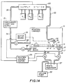
- Figure 1A shows a sealed reaction chamber 10 in which a multiplicity of reaction columns 11 are located.
- a flush column 12 is also situated within the reaction chamber.
- Each reaction column 11 contains an open inlet end 13 and an outlet end 14 which empties into exit basin 17 .
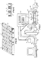
- the columns 11 are formed into a carrier plate 8 , the details of which are shown in Figures 1B and 1C.
- Carrier plate 8 when inserted into the reaction chamber, fastens to a bulkhead 16 to seal the reaction chamber 10 from the exit basin, thereby allowing atmospheric communication between reaction chamber 10 and exit basin 17 only through the reaction columns 11 .
- a movable reagent outlet 18 is mounted on a sliding carriage 30 which is driven by motive means 19 to position the outlet 18 over the inlet end of each of the reaction columns in the reaction chamber 10 .
- Chemical agents are stored in reservoirs R 1 through R n and are delivered through valves and tubing in the supply system 20 over supply line 33 to the movable reagent outlet 18 .
- An inert gas supply 21 supplies gas under pressure over line 35 to each of the reservoirs R 1 through R n . By pressurizing the reservoirs, the liquid reagent is caused to move into the supply line when the outlet valve associated with the reservoir is opened.
- Inert gas is also provided from supply 21 through lines 36 and 36' together with bleeder valve V 1 to the reaction chamber 10 . Inert gas is sent to the exit basin 17 through lines 36 and 36'' together with valve V 2 .
- a vacuum pump 22 is connected to the exit basin through valve V 3 and line 46 in order to evacuate basin 17 and draw any reagent chemicals located in the reaction columns to waste reservoir 37 .
- Vacuum pump 22 also acts to evacuate the flush column 12 through valve V 4 and line 45 in order to draw any chemicals which have been flushed into column 12 into the waste reservoir 37 .
- a reaction control center 23 is connected to control all of the valves within the system as well as the motive means 19 in order to control the additions of reagent chemicals in the proper sequence to each of the reaction columns.
- FIGS 1A-1C show a movable carrier plate 8 with reaction columns 11 formed therein.
- Each of the reaction columns contain a porous support material 7 appropriately derivatized for the desired reaction.
- each chemical will be sustained by the porous material to saturate and interact with the derivatized support for a desired incubation period until drawn through the porous support 7 by the application of a pressure differential to the inlet and outlet ends of the reaction columns.
- the reaction columns are conveniently formed in the carrier plate 8 for manual movement of the columns into and out of reaction chamber 10 .
- Figure 1B shows a carrier plate 8 with the columns 11 in a two dimensional matrix with 48 reaction columns in the array.
- the invention contemplates carrier plates with 100 or more reaction columns for concurrent synthesis of 100 or more sequences.
- Motive means 19 provides two dimensional motion to movable outlet 18 so that it can be positioned over any selected column.
- Figure 2 shows a laboratory prototype built according to the principles of the invention shown in Figure 1.
- a reaction chamber 10 contains a multiple number of reaction columns 11 which are positioned in a single row rather than in a two dimensional array.
- the actual number of reaction columns in the laboratory prototype may be as high as 32 although Figure 2 does not show quite that many.
- Reaction columns 11 in the prototype were built to utilize Luer fittings as explained in detail below and are therefore of a different construction from the carrier plate arrangement shown in Figures 1B and 1C.
- the movable reagent outlet (supply line outlet) 18 is positioned on a slide 30 which is moved back and forth along rails 31 .
- Slide 30 is connected to a drive belt 32 which is driven through motive means 19 (shown in Figure 1).
- the supply line outlet 18 is connected through line 33 to a reagent supply system 20 .
- System 20 contains a valve manifold shown in detail in Figure 3, together with all of the chemical reservoirs needed for the particular process to be performed by the apparatus.
- Ten reservoirs are shown in Figure 2 for an exemplary process performed by the prototype.
- the pressurized inert gas supply 21 is connected through line 35 to all of the reservoirs although the connections to each reservoir are not specifically shown in Figure 2.
- Line 36 carries inert gas to the reaction chamber 10 and to the exit basin.
- Basin 17 is also connected to the vacuum pump 22 through waste reservoir 37 .
- a personal computer 38 is used to control the sequence through which chemicals are added to the reaction columns to produce the desired oligonucleotide in each column.
- the computer 38 acts to control the movement of outlet 18 , the operation of the valves, the timing of the reactions, in short, the entire process.
- Output of computer 38 is provided through an input/output (I/O) board 39 and a relay board 40 .
- the system also includes a 24 volt power supply 41 and a parallel expansion board mounted within the frame of computer 38 .
- a stepper motor is used as the motive means 19 (shown in Figure 1) to position the reagent outlet 18 in accordance with the control sequence.
- the motive means 19 is under the control of a stepper motor controller 42 .
- the controller 42 is connected to the computer 38 which is the ultimate control over the positioning of the reagent outlet 18 by the stepper motor.
- Figure 2 also shows a pressure regulator 43 for regulating inert gas pressure and a vacuum gauge 44 .
- Figure 3 shows some details of the prototype reagent supply system 20 .
- the system consists of reagent bottle reservoirs 50-59 , valves 60-71 , reagent outlet supply lines 33, 33' and 33'' , and inert gas pressurization line 35 connected to each of the reservoirs.
- Figure 3 shows that the wash chemical located in reservoir 50 is located within the supply system so as to flush out the entire supply line when the associated valves are operated.
- operation of valve 71 acts to wash lines 33' and 33 while operation of valve 60 acts to wash lines 33'' and 33 .
- the system can be easily expanded or contracted to supply a different number of reagents.
- Figure 4 is a close-up view of the reaction chamber 10 showing the 32 reaction columns 11 in the laboratory prototype.
- Figure 4 shows the reagent supply line outlet 18 located on a slide 30 which moves back and forth on rail 31 (and rail 31' shown in Figure 5).
- Slide 30 is connected to drive belt 32 which is mounted on pulleys 80 and 81 .
- motive means 19 is connected to drive pulley 81 .
- Inert gas is introduced into the reaction chamber 10 through line 36' and into the exit basin 17 by line 36 '' . Vacuum is supplied to the flush column 12 by means of line 45 while line 46 applies a vacuum to the exit basin 17 .
- Figure 5 is an end or side view of the reaction chamber 10 with the side wall removed, and shows clearly that the slide 30 is mounted on two guide rails 31 and 31' .
- the drive pulley 81 is connected to stepper motor 19 through a flexible coupling 94 .
- the reaction chamber 10 is sealed to the atmosphere of the room in which it is located through top, back and bottom walls 92 , 93 , and 96 , respectively, through side walls, not shown, and through a removable front transparent face 90 which is sealed to the top, bottom and side walls of the reaction chamber through seal 91 .
- the exit basin 17 is a hollowed out portion of a solid frame 17'.
- the bulkhead 16 is sealed to the top of the solid frame 17' by means of the seal 95 such that the exit basin 17 is not connected to the atmosphere in the reaction chamber 10 except through the Luer fittings 15 which receive the reaction columns 11 .
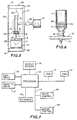
- Figure 6 shows a close-up view of a cylindrically-shaped reaction column 11 used with the prototype of Figure 2.
- the column 11 has a conically-shaped outlet end for insertion into a mating Luer fitting 15 .
- the reaction column contains a porous frit 9 with the support 100 placed on the frit 9 .
- a second frit 9A is located over the support 100 .
- the support is made of Controlled Pore Glass (CPG) which is of a specified bead size with pores therein of a specified size.
- Starter material for the reaction desired is comprised of a support material such as CPG, appropriately derivatized with a protected nucleoside (A, C, T or G) as dictated by the 3' nucleoside of each sequence to be synthesized.
- the CPG support of specified size with the proper derivatized nucleoside is commercially available and is placed in the reaction column.
- the derivatized nucleoside support may also be produced using the apparatus of this invention.
- FIG. 7 shows the major components of the reaction control center 23 .
- a processor 110 is connected to a read-only memory (ROM) 111 and a random access memory (RAM) 112 .
- ROM read-only memory
- RAM random access memory
- a hard disk drive 113 and a diskette drive 114 are included in the system for conveniently storing the sequences of oligonucleotides to be produced.
- An input means such as keyboard 115 and an output screen 116 enable interactive communication between the user of the system and the processor 110 .
- the output line 117 carries output signals to the valve control unit 118 and the motor control unit 119 in order to position the reagent supply line outlet 18 to the correct reaction column and place into that reaction column the correct chemical reagent in accordance with the sequence being processed by the apparatus.
- the various oligonucleotide sequences to be produced by the device Prior to the operation of the instrument, the various oligonucleotide sequences to be produced by the device are entered into a text file and located on either a diskette for use in the diskette drive 114 , or on a hard disk located in the disk drive 113 .
- a program to control the operation of the valves and the motor is located in RAM 112 .
- the control program accesses the desired text file and directs the automated synthesis of DNA according to the sequences found therein.
- An example of 32 nucleotide sequences for synthesizing 32 particular oligonucleotides is shown in Table 3 infra.
- the 32 columns of the prototype device are filled with the appropriate support material.
- the columns are conveniently located on a carrier plate 8 which is moved from the preparation area and inserted into the reaction chamber 10 .
- the supports can contain different nucleoside materials one from another so that different sequences can be produced concurrently in the inventive device.
- the transparent front plate 90 is fastened in place to produce an airtight reaction chamber 10 .
- Reagent bottles are filled with appropriate reagents and capped tightly.
- the reagent supply system is pressurized to about 7.5 psi with inert gas, for example, argon.
- Reagent lines from the bottles to the valves are primed by individually switching the appropriate valves.
- the vacuum pump is turned on and the vacuum adjusted to about 20 inches of mercury.
- Manual valve V 1 , Figure 1, as well as any manual valves associated with the argon tank 21 are opened to flood the reaction chamber.
- a cycle consists of the following reactions: deblocking (detritylation), coupling, oxidation and capping.
- An acetonitrile wash follows each reaction.
- the deblocking step proceeds as follows. First, the outlet 18 is moved by motor 19 to the flush column 12 . Valve 70 is operated so that deblocking reagent 51 flows into the supply lines 33 and 33' in sufficient quantity to prime them. Flow occurs through two position latching valve 66 which is positioned to connect supply lines 33 and 33' . During the flushing and priming operation, vacuum is applied to the flush column 12 through valve V 4 so as to remove reagent from column 12 through the line 45 to the waste reservoir 37 .
- valve 70 is closed and the outlet 18 is moved successively to each position in the support array. While outlet 18 is positioned over each support, valve 70 is briefly opened for the time needed to deliver an appropriate volume of reagent to each support.
- the deblocking reaction proceeds for an appropriate incubation time after which the reagent is removed from the reaction columns. Removal of the deblocking reagent from the reaction columns is accomplished by opening valve V 3 to apply vacuum to the exit basin. Through that action all columns which have received the deblocking reagent are evacuated.
- valve V 2 is opened to admit argon into the exit basin 17 in order to equalize pressure above and below the frit 9 . Equalization of pressure on the frit is needed so that when a reagent is applied to a column, it will saturate the support for the entire incubation period until removal of the reagent occurs through application of vacuum.
- a second pass of the movable outlet 18 is made over all of the columns to be coupled to provide the deblocking reagent a second time, after which incubation and removal is once again carried out.
- the deblocking operation often consists of four passes.
- the deblocking reagent used in a typical DNA synthesis is a dichloroacetic acid as shown in Table 1 below.
- Table 1 also presents other examples of chemical reagents for use in synthesizing the oligonucleotide sequences shown in Table 3, infra. It should be understood that the particular chemicals shown in Table 1 are illustrative of those chemicals used in a successful operation but the apparatus and methodology of the invention are not limited to any specific coupling chemistry.
- two position latching valve 66 is positioned to connect lines 33'' and 33 , and valves 61 and 62 are alternately opened and closed in a rapid manner to place amidite and activator into the supply lines 33'' and 33 .
- the valves 61 and 62 are operated under the control of computer 38 to provide a desired mixture ratio, which is shown as 1.8:1 activator to amidite in Table 2.
- valve 66 is positioned to connect lines 33' and 33 and valves 68 and 69 are alternately opened and closed in a rapid manner to place Cap A and Cap B solutions into the supply lines 33' and 33 .
- the desired mixture ratio of Cap A and Cap B is 1:1 as shown in Table 2.
- the step of coupling in the inventive procedure makes use of an asynchronous coupling concept in that the addition of each nucleotide reagent proceeds to non-adjacent columns until each support requiring that reagent has received it.
- the control program determines which of the 32 supports require "A,” carries out the addition of A to all identified supports, then determines which require "C,” carries out the C additions, and so forth, until all supports have received the required nucleotide reagent.
- Asynchronous coupling leads to economy in reagent use and to speed of operation.
- Economy occurs by avoiding the flushing and priming steps which might otherwise repeatedly occur in a sequential column to directly adjacent column operation when one column calls for A, the next for C, the third for A again, then T, etc.
- By limiting the need for incubation periods and flush and prime operations the speed of operation is improved, and as the number of columns increase the benefit becomes more pronounced. This advantage results since the time to move the outlet from column to column is small compared to incubation times.
- the inventive procedure allows for the parallel synthesis of oligonucleotides of different lengths.
- a support bearing an oligonucleotide whose synthesis has been completed will be ignored until the other syntheses are completed. All supports are oxidized and capped and if desired, all oligonucleotides are then detritylated simultaneously during a final detritylation step.
- the instrument allows for synthesis of less than 32 oligonucleotides. If the input file contains only one sequence, or only six sequences, for example, reagents are delivered to only one column or to only six columns, respectively.
- the reaction columns are removed from the instrument.
- Front plate 90 is unfastened and the carrier plate 8 is removed from the reaction chamber 10 to a work bench, carrying with it all of the reaction columns 11 .
- the DNA products may then be cleaved from their supports and subjected to conventional deprotection as is known. If desired, the DNA products may also be further purified according to well-known methods.
- a second carrier plate 8 can be prepared with the proper supports inserted into each of the columns in the second carrier plate for a second synthesis operation.
- the second carrier plate is then moved to the reaction chamber so that a second automated synthesis operation can commence immediately.
- the deprotection steps on the first batch can be performed, after which the first carrier plate can be readied with the proper supports for a third batch. In that manner, economy of labor is achieved. All of these manual steps, however, can be avoided by using the machine to produce the derivatized supports directly in the appropriate column.
- the control program for the process is read into the system from either the disk drive 113 or the disk drive 114 and stored in RAM 112 for the actual processing operation.
- the input data (text files) for the sequence of adding the base reagent chemical, that is A, C, T or G, for each sequence to be produced, such as in Table 3, must also be read into the system. This may be accomplished from the disk drive or diskette drive if the sequences have been previously prepared, or they may be entered into the system from the keyboard 115 with an interactive display on output screen 116 for the computer user.
- both the control program and the input data for the sequences to be produced must be read into RAM 112 .
- the input data represented in Table 2 must also be read into RAM to provide the number of additions for each reagent and the timing of the various steps of the process.
- the initial set up process calls for the loading of each of the reagent chemicals into the proper reservoir in accordance with the scheme shown in Figure 3.
- An important aspect of the set up procedure is to load the columns to be coupled onto the carrier tray 8 . This is conveniently done on a work bench from which the carrier tray is moved for insertion into the reaction chamber where each column is positioned properly within its associated Luer fitting 15 .
- the reaction chamber is sealed by fastening plate 90 onto the front of the reaction chamber 10 .
- the location of specific supports in specific columns to be coupled must be coordinated with the sequence data in the control center. In that manner, the addition of chemicals in the proper order will be made to the proper column in the proper sequence. For example, with reference to Table 3, columns containing the proper support corresponding to the 3' end of the Table 3 sequence are loaded into the carrier tray in the order shown.
- columns containing T support are placed into positions 1, 2, 12, 18, 19, 20, 22, 26 and 32.
- Columns containing G support are placed into positions 3, 4, 11, 23, 24 and 31.
- columns with A support and columns with T support are located on the carrier tray at positions corresponding to the 3' data of Table 3.
- Manual valves associated with the gas supply tank 21 are opened so that the pressurized inert gas flows into line 35 to pressurize each of the reservoirs.
- the gas also flows into line 36 and to the reaction chamber 10 to flood the chamber with inert gas.
- a manual bleeder valve, not shown, for the reaction chamber may be opened during this operation so that all of the air in the chamber is displaced as the inert gas enters. If needed, valve V 2 may be opened and valve V 3 closed so that inert gas flows into the exit basin.
- the apparatus is ready to begin the process of synthesizing oligonucleotides.
- the operation of the control program is shown in Figure 8 where the first step 200 is to deblock all supports to be coupled. It should be observed that while 32 supports may be positioned within the prototype unit, the actual number of supports to be coupled may vary from 1 to 32 on any particular run.
- the chemistry of synthesizing DNA is well known and therefore will not be explained in detail.
- the general object of the deblocking operation at step 200 is to remove the 5' blocking elements from the derivatized nucleosides attached to the supports. Removal of the blocking elements enables the nucleosides to be reactive to the application of coupling reagents.
- step 201 the supply line is flushed and all of the deblocked supports are washed at step 201 .
- This step ensures that all of the deblocking chemical reagent has been removed prior to performing the next step 202 which is the coupling of all supports requiring addition of the nucleotide reagent "A" which is the common designation for reagent containing the base "adenine".
- the next step 203 in the inventive process is to couple all supports requiring the nucleotide reagent "C” which is the common designation for reagent containing the protected "cytosine" precursor.
- C nucleotide reagent
- G is the common designation of the nucleotide reagent containing the base "guanine.”
- coupling all supports requiring the base "T” is carried out.
- T is the common designation for the nucleotide reagent containing the base "thymine.” It should be noted that operation of the inventive apparatus is herein exampled through the use of a specific coupling chemistry making use of the above named A, C, T and G nucleotide reagents. Collectively, these reagents are often referred to as “phosphoramidite” or “amidite” reagents to distinguish them from other currently known coupling chemistries such as the “phosphotriester” and “phosphonate” chemistries.
- the inventive apparatus appropriately programmed, can be used with coupling chemistries other than the one chosen herein to exemplify the operation of the machine.
- the query at step 211 results in a branch to step 212 for deblocking the supports and washing them at step 213 .
- the supports may then be removed from the reaction chamber to the work bench for final workup involving conventional deprotection.
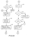
- Figures 9A-9B are a more detailed description of the procedure performed in carrying out each of the steps of the process shown in Figure 8.
- the first operation as shown at step 250 in Figure 9 is to set the number of times, n, that the deblocking reagent is to be added to each column in order to provide a total of 0.7 ml of the reagent.
- the control program makes reference to input data shown in Table 2, to ascertain the number of additions for the deblocking step.
- the control program sets the control parameter n to equal four at step 250 .
- the reagent supply line outlet 18 is moved to the flush column 12 .
- the appropriate valves are opened in order to prime the supply line 33 with the deblocking reagent in reservoir 51 .
- valve 66 is positioned to connect lines 33 and 33' and valve 70 is actuated to connect reservoir 51 with line 33' .
- valve 70 is closed.
- the valve V 4 is operated to drain the flush column.
- the column numbers to be coupled are read by the control program at step 254 from input data such as Table 3 and the outlet 18 is moved by the stepper motor to the first column to be coupled at step 255 .
- the outlet 18 is moved by the stepper motor to the first column to be coupled at step 255 .
- Oligo ID # 096A will be synthesized in the first column of the linear column array and oligo ID # 095B will be synthesized in the 32nd and last column of the array.
- the prototype device can operate to synthesize any number of oligonucleotides from one to 32, with input data such as Table 3 for any particular operation read into the computer system.
- outlet 18 is first moved to the first column at step 255 .
- Valve 70 is opened at step 256 for the period of time needed to provide the proper amount of deblocking reagent (.175 ml) to the first column. Thereafter, valve 70 is closed, and at step 257 the query is asked whether the step has been completed for all columns to be coupled (in this instance, are all columns deblocked). Since at this point in the procedure the deblocking reagent has only been added to the first column, the answer is "no," and a return is made to repeat steps 255 through 257 until all columns to be coupled have received .175 ml of deblocking reagent.
- reagent outlet 18 is moved to the flush column at step 258 and at step 259 the system waits until the incubation time needed for the deblocking reagent to unmask the 5' ends of the nascent oligonucleotides has been completed. Table 2 identifies that time as 15 seconds.
- valve V 3 is opened to apply a vacuum to the outlet end of all of the reaction columns to drain the deblocking reagent from the columns that are to be coupled.
- Valve V 3 is then closed and valve V 2 is opened at step 261 to introduce argon into the vacuum chamber to equalize pressure on both the inlet and outlet ends of the columns.
- n is set equal to n - 1 at step 262 , which at this point in the deblocking operation results in setting n to 3.
- the query is whether n is equal to 0, and since it is not, a return is made to repeat steps 254 through 263 in order to add deblocking reagent for a second time to all of the columns to be coupled.
- n is equal to 0 and the query at step 263 identifies that the deblocking operation has been completed.
- n is initially set to five at step 250 , as shown in Table 2, and at step 252 , the valve which is opened and closed is valve 71 , as may be seen by reference to Figure 3.
- the flush column is drained at step 253 and at step 254 , all columns to be coupled are identified.
- Steps 255-257 are performed until all columns to be coupled (32 in this case) contain the wash chemical.
- step 202 ( Figure 8) is entered to couple all of the supports requiring the addition of reagent A.
- the detailed procedure for carrying out step 202 is shown in Figure 9.
- the number of additions for the coupling step is set equal to 3 at step 250 , as shown by Table 2, and valves 61 and 62 are opened and closed at step 252 to prime the supply line.
- Valve 66 is also operated to connect lines 33'' and 33 .
- an activator is also introduced into the supply line together with the reagent A. This is preferably accomplished by rapidly opening and closing valves 61 and 62 during step 252 to mix the amidite and the activator in the priming of supply line 33 .
- the flush column is drained at step 253 and the column numbers to be coupled with the amidite A are ascertained at step 254 by referring to the sequence input data in Table 3.
- Table 3 shows the sequence in which couplings are carried out.
- the 3' nucleotide is derived from a previously produced starter support which is placed in the appropriate column as part of the set-up procedure.
- the first couplings to be produced in the machine add the second base from the 3' end in Table 3. Therefore, the first addition of A is to the supports in columns 3, 4, 6, 11, 15, 16, 23, 24, 27 and 28.
- the first addition of C is to columns 1, 7, 8, 12-14, 22 and 26.
- G's and T's are accomplished and so on as the synthesis proceeds in the 3' to 5' direction for the sequences shown in Table 3.
- the outlet 18 is moved at step 255 to the next column to be coupled, that is, the first column to receive the addition of reagent A, column 3.
- the valves 61 and 62 are again opened and closed in a rapid manner to deliver a mixture of amidite A and activator to column 3.
- the amidite/activator mixture is delivered for a time sufficient to provide 0.1 ml to column 3 on this first of three additions so that a total of 0.3 ml is delivered when all three passes are complete.
- step 257 a branch is made to step 255 for positioning the outlet 18 at the next column to receive amidite A, that is, column 4.
- Step 256 is performed to add 0.1 ml of amidite A/activator to column 4 after which the procedure of steps 255 and 256 are repeated for columns 6, 11, 15, 16, 23, 24, 27 and 28.
- step 400 one of three procedures is selected for continuing the operation. These three separate procedures are illustrative of the many variations which can be made in the processes which utilize the inventive apparatus without parting from the spirit and scope of the invention. For example, if procedure E1 is selected, the coupling steps are performed in the same manner that has already been explained above with reference to the deblocking and washing steps. If procedure E2 is selected, the procedure is a variation of the E1 procedure except that certain steps are skipped as explained below. If procedure E3 is selected, a considerably different alternative procedure will be performed as explained below.
- step 259 the incubation period for the amidite A (15 seconds) is completed, after which the coupled columns are drained at step 260 and pressure is equalized at step 261 . Since the first pass of adding the amidite A is now completed, n is set to 2 at step 262 , and since n is not zero, a branch is made at step 263 to step 255 for the second pass of adding amidite A.
- step 263 results in a return to Figure 8, step 203 , for adding the amidite C.
- FIG. 9A and 9B The process shown in Figures 9A and 9B is again carried out for the washing operation of step 206 with valve 60 opened in order that the supply line 33' ' for the activator and amidite chemicals may be washed.
- the process shown in Figures 9A and 9B is performed again during the oxidizing step 207 by activating valve 67 with valve 66 operated to connect lines 33' and 33 .
- Another wash step is performed at step 208 involving valve 71 and then all of the coupled supports are capped at step 209 .
- valves 68 and 69 are alternately opened repeatedly to provide a mixing of the two capping reagents in supply line 33 .
- the coupled supports are again washed at step 210 .
- step 211 the query of whether any further couplings are to be performed is answered in the affirmative since only the first coupling has been completed at this point.
- Table 3 shows that the particular synthesis under preparation is to provide oligonucleotide primers with base couplings ranging from 20 to 25 in length. Consequently, a branch is taken at step 211 to step 200 to repeat the entire process described above in order to add the second base coupling to each sequence.
- the support in column 1 will receive an A; the support in column 2 will receive a C; the support in column 3 will receive a G and the support in column 32 will receive a G.
- step 211 the query of whether further couplings are to be performed is answered in the negative and a branch is taken to step 212 .
- Steps 212 and 213 are optional steps that contemplate further oligo processing on a work bench as described above. Since some purification methods take advantage of the presence of the trityl group, steps 212 and 213 may not be desirable. If the steps are performed at step 212 , a deblocking (detritylation) reagent is added to all columns and, after deblocking, all columns are washed at step 213 . The front cover 90 is removed and the 32 support columns 11 are removed from the reaction chamber 10 .
- Table 4 shows the yields for each of the 32 oligonucleotides produced.
- Total yields were based on optical density measurements of purified oligonucleotide recovered from preparative gels, and show an average total yield of approximately 500 micrograms for each sequence.
- the run was completed in 6 hours, with consumption of reagents during the run only about one-quarter of that to produce a similar sequence in a prior art commercial single column synthesizer even though no serious attempt was made to optimize reagent usage in the prototype.
- the time required to synthesize 32 oligonucleotides using the prototype synthesizer is markedly less than that required by prior art single column or four column synthesizers.
- the innovative principals of operation embodied in the prototype that is the "open" flow path with the inlet of each column to be coupled opened to the atmosphere of the reaction chamber, the motion controlled reagent outlet, which can move from support to support, the exit basin coupled to each of the multiple columns, and the controlled atmosphere of the chamber make it possible to further increase the concurrent production of oligonucleotide primers by simply increasing the number of columns in the device, either by adding columns to the linear array or by providing a two dimensional array of columns. Changes in hardware and software to accommodate additional columns beyond 32 are minimal, which is in sharp contrast to prior art systems. Such systems are tightly plumbed from the reagent supply system to all of the individual columns making the addition of columns a difficult matter.
- One of the advantages of the inventive process described herein is that a single priming of the delivery line is all that is necessary for each amidite added during a cycle.
- priming consumes significant quantities of reagent
- the saving in reagent consumption is significant compared to prior art devices which have delivery lines to each column.
- the advantages of the inventive process become even more important.
- the effective change over of reagents during the various steps improves reagent economy, but the removal of reagents through the application of vacuum is also a significant improvement leading to economy in the amount of reagent needed. As the vacuum draws off the reagent, the column is dried thus providing more efficient use of the next reagent.
- the inventive apparatus may be operated in several fashions to produce the synthesis; flexibility is a feature of the automated apparatus.
- one of three procedures could be selected.
- the procedure according to the branch E1 was selected and explained above. However, should the user of the apparatus have selected the procedure E2 , a branch would be made to Figure 9C.
- the first entry into procedure E2 is when the first pass for adding amidite A is completed and the movable outlet has been moved to its home position over the flush/prime column 12.
- the query of whether an amidite A, C, T or G has been added, has resulted in a branch to step 400 where the procedure E2 was selected.
- n was set equal to 3 at step 250 to provide for three additions of amidite A, and since one pass is now complete, n is set to two at step 258B . Since n is not zero, a branch is made at step 258C to step 258D to wait for completion of the 15 second incubation period after which return is made to step 255 for the second pass of adding amidite A.
- step 255 a return is made to step 255 without first draining all the coupled columns and equalizing pressure above and below the frits. These steps can be skipped if the porosity of the frits are such that the reagent has substantially drained away from the support during the 15 second incubation period.
- step 258C results in a branch to step 258F to wait for the incubation period.
- step 258G all the coupled columns are drained at step 258G and pressure above and below the frits is equalized at step 258H .
- step 203 for adding the amidite C.
- the inventive apparatus may also be operated to produce faster turnaround at the expense of using some additional reagent chemicals by altering the control program as shown in Figure 10 through the selection of E3 at step 400 .
- the supply line is flushed and primed with the next reagent, for example, C.
- the operation proceeds to add reagent C without waiting for the conclusion of the relatively long incubation period of 15 seconds.
- the next reagents T and G are added as required after which the process waits for a single incubation period of 15 seconds. All coupled columns are then drained simultaneously.
- the initial set up procedure is the same as described above and the first two steps shown in Figure 8, steps 200 and 201 , to deblock and wash all supports to be coupled proceed as previously described.
- the control program first determines whether the reagent A is to be added. In the example synthesis of Table 3, A is required and therefore step 202 to add reagent A is performed.
- the steps 250-258A shown in Figures 9A and 9B, are performed to complete a first pass of adding A to all supports requiring that reagent.
- the query at step 258A results in a branch to step 400 and to E3 in Figure 10 in the alternative procedure.
- step 300 a determination is made that the reagent A has been added. This determination is made within the control program which calls for the addition of A at step 202 , if required, and the input data of Table 3, which has required the addition of A. Alternatively, this determination could be performed by feedback from the process apparatus.
- step 301 the input data of Table 3 is inspected to determine whether the addition of reagent C is required. Since it is, the supply line is flushed of A and primed with C at step 302 following which steps 255-257 are repeated until an addition of nucleotide reagent C has been made to all columns requiring that reagent.
- the query at step 257 then results in a branch to step 258 for moving the supply line to the flush/prime column, and a branch is again taken to E3 in Figure 10.
- Step 300 results in a branch to step 303 since A was not added on this loop through the procedure.
- the control program notes that the reagent C has been added.
- the input data of Table 3 is reviewed at step 304 to determine whether the reagent G should be added. Since the input data includes G, the supply line is flushed of C and primed with G at step 305 . Steps 255-257 are again repeated until the addition of G has been made to all columns requiring that reagent. Steps 258 and 258A are then performed resulting in another entry E3 to step 300 in Figure 10.
- step 306 results in a branch to step 307 to determine whether reagent T is required.
- the input data of Table 3 is reviewed and since the reagent T is to be added, the supply line is flushed of G and primed with T at step 308 .
- Steps 255-257 are again performed to add T to all supports requiring that reagent.
- Steps 258 and 258A again lead to entry at E3 into Figure 10.
- Steps 300 , 303 , and 306 all result in negative determinations but at step 310 a branch is taken to step 311 to wait for completion of the required incubation period of 15 seconds. After completion of the incubation period, all columns are drained at step 312 and pressure differentials above and below the frits are equalized at step 313 .
- n is changed to 2 at step 314 signifying, in this instance, that a completed first pass has been made for all reagents to be added. Since n is not zero, a branch is made at step 315 to step 316 to inquire whether the reagent A is to be added. Since the input data of Table 3 require A, the supply line is flushed of T and primed with A at step 317 . A return is made to perform steps 255-257 until all supports requiring reagent A have received an addition. Steps 258 and 258A again lead to entry E3 into Figure 10.
- step 315 results in a branch to step 206 , Figure 8, to wash all of the coupled supports.
- step 206 Figure 8
- the inventive apparatus and procedure is of value in many situations requiring fast, economical production of large numbers of DNA (or RNA) oligonucleotides.
- one such situation is in molecular genetic research where synthetic DNA's are used as primers in DNA sequencing by the dideoxy method.
- One strategy for obtaining long sequences by the dideoxy method is that of "primer-walking.”
- a long template is prepared and sequencing is initiated from one end. The sequence is read as far as possible and a new primer is chemically synthesized based on sequence near the end of the first "read.”
- the new primer is used to initiate a second round of sequencing thereby extending the initial sequence. Repetition of the process generates a long contiguous sequence which is limited, in principal, only by the length of the template.
- each step in the walking process requires synthesis of a new template-specific primer.
- Parallel dideoxy sequencing of multiple long templates by a primer-walking strategy has the potential of dramatically accelerating the acquisition of sequence data by reducing the labor and expense associated with preparation of large numbers of short templates and also by reducing the effort involved in reassembling long contiguous sequences. Cost effective implementation of the parallel primer-walking approach for large scale sequencing projects is made practical by this invention.
- Figures 2-7 The specific prototype of Figures 2-7 described has one row of columns and one supply line outlet.
- a two dimensional array of columns is shown in Figure 1B and an outlet capable of two dimensional motion is provided for use with that array.
- the apparatus could have more than one movable outlet and more than one flush/prime column. In that manner, during the 15 second incubation period for amidite A, the second outlet could supply amidite C, for example; or, the second outlet could serve an entirely different group of columns.
- the prototype does not include sensing devices to provide feedback data for closed loop operation. That type of operation has not been needed to date, but obviously such control could be added to the instrument, for example, if the device is built to have 100 or more columns, feedback control might become desirable.
- the possibility of misplacing a support increases for a prototype with 32 columns, and as the number of columns increase the job becomes more and more tedious and error-prone.
- the inventive apparatus exampled here by the 32 column prototype can be further developed and expanded to accommodate concurrent synthesis of 100 or more oligos as mentioned above with respect to the two dimensional array of Figure 1B.
- the inventive apparatus can also be used to produce the initial derivatized support material, and it can be done using the same array that will be used in the subsequent synthesis process.
- the support material may be a porous frit-like material suitable for direct derivatization.
- the appropriate derivatization chemicals are placed in the reservoirs of Figure 3 so that supply line 33 can contain the appropriate reagent in the sequence of the derivatization operation.
- a control program to operate the valves and to move outlet 18 must be provided together with input information providing the amount of reagent to be added, the number of additions and the incubation periods.
- the instrument can be used, if desired, for the production of derivatized supports in a carrier plate 8 as shown in Figure 1B without thereafter directly proceeding to the synthesizing process. In that manner, a number of derivatized supports can be accumulated for subsequent synthesizing operations.
Landscapes
- Chemical & Material Sciences (AREA)
- Organic Chemistry (AREA)
- Chemical Kinetics & Catalysis (AREA)
- Saccharide Compounds (AREA)
- Apparatus Associated With Microorganisms And Enzymes (AREA)
Abstract
Description
- This invention relates to apparatus and method for carrying out the automated chemical synthesis of oligodeoxynucleotides and, in particular, the synthesis of multiple different oligodeoxynucleotides in a concurrent manner.
- The art of synthesizing DNA has progressed to include automated instruments for concurrently producing multiple DNA segments, that is, oligodeoxyribonucleotides, a term that is frequently shortened to oligodeoxynucleotides and shortened further to oligonucleotides. These machines often make use of reaction columns in which a support material for the reaction is positioned within the columns between inert, porous filters, referred to as "frits." The reaction columns are placed within the automated apparatus so that chemicals can be added to the columns in sequence and in appropriate amounts in an automated fashion. The object is to synthesize the desired oligonucleotides from a starter material bound to the support.
- Currently known automated synthesizers can produce only a few oligonucleotides at a time limited by the number of reaction columns located within the machines. The number of reaction columns is limited as a practical matter by the increased complexity of the plumbing and valving network as the number of columns increase since currently known synthesizers provide a tightly plumbed network from the several reagent supply reservoirs to each reaction column. As a result, conventional automated synthesizers typically provide for automated synthesis of only one to four primer length (typically 20-mer) oligonucleotides in several hours. If a four column unit is operated three times in an 8-hour workday, twelve primers can be produced. To produce 100 oligonucleotide primers per day requires eight of these expensive machines. Also, the cost of the expensive reagents and the labor associated with the synthesis of 100 primers is high. While improvements in the production of primers holds great promise for research and development activities in many areas, including, for example, the effort needed to sequence the entire human genome, the automated synthesizers currently available are inappropriate for many applications in terms of throughput, operating costs and yields.
- In addition to the production of primer length oligonucleotides currently known synthesizers can produce much longer oligonucleotides, i.e., greater than 100 nucleotides in length. The time to produce a 100 nucleotide DNA is approximately five times longer than the production of a 20 nucleotide DNA.
- It is, therefore, an object of this invention to provide an instrument that uses considerably less reagent material for equivalent yields, reduces labor cost in the operation, keeps the initial expense of the machine within reasonable limits by limiting the complexity of the machine and enables the production of hundreds of primers each day.
- US-A-5053454 discloses an apparatus for simultaneously performing a multiplicity of synthesis reactions. The synthesizer includes at least one reaction vessel having an access port and a synthesis compartment adjacent the access port. A closable exit channel with an exit port is adjacent the synthesis compartment. The apparatus also includes a base having a plurality of inlets, each of the inlets configured to receive the exit channel of the reaction vessel. A fluid outlet is present that is in communication with the plurality of inlets. A vacuum pump and vacuum line are connected to the fluid outlet for sucking excess reagents and by-products from the reaction vessel.
- US-A-5112575 discloses a polynucleotide synthesizer comprising a supply mechanism for supplying a) liquid reactants for synthesizing peptides or polynucleotides, b) liquid reagents that assist in the synthesis, and c) a wash liquid; a reactor column; a connecting device for fluidly connecting the supply mechanism with the column; apparatus for positively displacing with gas pressure, liquid reactants and reagents, and wash liquid from the supply mechanism into the connecting device; and a controller connected to the column for allowing liquid to flow under the force of the gas pressure and at a controlled rate, into a temporary storage chamber and for thereafter emptying the chamber.
- US-A-4517338 discloses a reactor system and method for synthesizing or degrading polynucleotides and other liner polymers. The system includes a tubular reactor connected to a reagent manifold. The polynucleotide is immobilized on a loosely packed solid-phase support material in the tubular reactor, and reagents are sequentially introduced into the tubular reactor. After each reagent is introduced, the tubular reactor is isolated from the reagent manifold and the reagent agitated by alternatively pressurizing the opposite ends of the tubular reactor. By connecting two or more tubular reactors to the reagent manifold, a plurality of polynucleotides having different sequences may be synthesized simultaneously.
- US-A-4671941 discloses an apparatus for synthesizing polynucleotides including a plurality of reactors, bottles charged with reagents and solvents, and change valve means for switching passages between respective bottles and the reactors. The apparatus also comprises mode selector means between a pressure source and the reactors for switching liquid supply or discharge operation and distributor means for closing or opening passages connected with the reactors to selectively operate the reactors.
- In the apparatus of this invention a reaction chamber contains one or more reaction columns in which a particular oligonucleotide sequence is synthesized. The inlet end of each reaction column is open to the atmosphere within the chamber and the chamber itself is preferably sealed and filled with an inert gas. The instrument has a movable supply line outlet located within the chamber. The outlet can be positioned above the inlet end of each of the columns so that nucleotide reagents, capping reagents, deblocking reagents, wash chemicals etc. can be provided to each of the columns. All of these reagents are located in a supply system which includes reservoirs and valving to connect the reservoirs with the supply line. A flush/prime column is also located within the chamber so that the supply line can be flushed and primed between each different chemical reagent addition. After supplying the appropriate reagent to each of the reaction columns, a pressure differential is applied to the columns to drain the reagent. Preferably a vacuum source is connected to the outlet end of the reaction columns to rapidly draw the chemicals from all of the columns simultaneously thus leaving the columns dry and ready to receive the next reagent.
- A removable carrier plate is provided for holding a plurality of reaction columns and enabling ease of movement of the reaction columns into and out of the reaction chamber. When assembled with the reaction chamber, the carrier plate seals the reaction chamber from an exit basin, allowing atmospheric communication between the chamber and the basin to occur only through the reaction columns.
- The reaction columns are comprised of a porous material and a reaction support material. The porous material sustains reagents to saturate and interact with the reaction support material until a pressure differential is applied to draw the reagents through the porous material to the exit basin. The support material may be a derivatized support such as controlled pore glass (CPG), placed in the column on a porous material such as a glass frit. Alternatively, the porous material may itself be appropriate for derivatization thereby combining the frit and support material within the reaction column. A process of directly derivatizing the support material can be carried out in the apparatus prior to the synthesizing process.
- In operating the apparatus according to a desired sequence of reagent application, each of the reaction columns is designated to receive a specific reagent. A computer with associated electronics and software controls all aspects of the process including the opening and closing of valves for the proper time period and in correct sequence, the movement of the supply line outlet, the provision of the proper incubation period for each reagent addition to the columns and the evacuation of the columns after the incubation period is complete.
- Asynchronous coupling is used, that is, when coupling the nucleotide reagents, a first such reagent is delivered to all columns requiring that base regardless of the position of the column. Columns not requiring the first reagent are skipped over by the movable outlet.
- The apparatus can be used for automating various processes by utilizing appropriate reagents in the supply system, appropriate control programs and appropriate reaction supports. As mentioned above, for example, reaction supports for synthesizing oligonucleotides may be directly derivatized in the apparatus and if performed directly prior to the synthesizing process, the carrier plate can remain in the apparatus for both the derivatization and synthesizing processes.
-
- Figure 1A is a block diagram showing the major components of the inventive apparatus. Figure 1B shows a carrier plate with reaction columns for assembly with the apparatus of Figure 1A. Figure 1C is a sectional view showing reaction support material located in the reaction columns of Figure 1B.
- Figure 2 is a schematic diagram of a laboratory prototype providing a specific version of the apparatus set forth in Figure 1.
- Figure 3 shows details of the reagent supply system used with the laboratory prototype of Figure 2.
- Figure 4 shows details of the reaction chamber of Figure 2, with 32 reaction columns located therein.
- Figure 5 is a side view of the reaction chamber.
- Figure 6 shows a typical reaction column used within the reaction chamber.
- Figure 7 is a block diagram of the major components in the control center of Figure 1.
- Figure 8 is a flow diagram of the method of operating the inventive apparatus.
- Figures 9A and 9B show detailed steps to implement each of the major steps of the method set forth in Figure 8. Figure 9C shows a variation on the method of Figure 9B.
- Figures 10A and 10B show an alternate approach to the methods of Figures 9B and 9C.
-
- With reference to the drawings, like numbers indicate like parts and structural features in the various figures.
- Figure 1A shows a sealed
reaction chamber 10 in which a multiplicity ofreaction columns 11 are located. Aflush column 12 is also situated within the reaction chamber. Eachreaction column 11 contains anopen inlet end 13 and anoutlet end 14 which empties intoexit basin 17. Thecolumns 11 are formed into acarrier plate 8, the details of which are shown in Figures 1B and 1C.Carrier plate 8, when inserted into the reaction chamber, fastens to abulkhead 16 to seal thereaction chamber 10 from the exit basin, thereby allowing atmospheric communication betweenreaction chamber 10 andexit basin 17 only through thereaction columns 11. Amovable reagent outlet 18 is mounted on a slidingcarriage 30 which is driven by motive means 19 to position theoutlet 18 over the inlet end of each of the reaction columns in thereaction chamber 10. - Chemical agents are stored in reservoirs R1 through R n and are delivered through valves and tubing in the
supply system 20 oversupply line 33 to themovable reagent outlet 18. Aninert gas supply 21 supplies gas under pressure overline 35 to each of the reservoirs R1 through R n . By pressurizing the reservoirs, the liquid reagent is caused to move into the supply line when the outlet valve associated with the reservoir is opened. Inert gas is also provided fromsupply 21 throughlines 36 and 36' together with bleeder valve V1 to thereaction chamber 10. Inert gas is sent to theexit basin 17 throughlines 36 and 36'' together with valve V2 . Preferably, avacuum pump 22 is connected to the exit basin through valve V3 andline 46 in order to evacuatebasin 17 and draw any reagent chemicals located in the reaction columns to wastereservoir 37.Vacuum pump 22 also acts to evacuate theflush column 12 through valve V4 andline 45 in order to draw any chemicals which have been flushed intocolumn 12 into thewaste reservoir 37. - A
reaction control center 23 is connected to control all of the valves within the system as well as the motive means 19 in order to control the additions of reagent chemicals in the proper sequence to each of the reaction columns. - Figures 1A-1C show a
movable carrier plate 8 withreaction columns 11 formed therein. Each of the reaction columns contain a porous support material 7 appropriately derivatized for the desired reaction. When reagent chemicals are added to thereaction columns 11, each chemical will be sustained by the porous material to saturate and interact with the derivatized support for a desired incubation period until drawn through the porous support 7 by the application of a pressure differential to the inlet and outlet ends of the reaction columns. The reaction columns are conveniently formed in thecarrier plate 8 for manual movement of the columns into and out ofreaction chamber 10. Figure 1B shows acarrier plate 8 with thecolumns 11 in a two dimensional matrix with 48 reaction columns in the array. The invention contemplates carrier plates with 100 or more reaction columns for concurrent synthesis of 100 or more sequences. Motive means 19 provides two dimensional motion tomovable outlet 18 so that it can be positioned over any selected column. - Figure 2 shows a laboratory prototype built according to the principles of the invention shown in Figure 1. A
reaction chamber 10 contains a multiple number ofreaction columns 11 which are positioned in a single row rather than in a two dimensional array. The actual number of reaction columns in the laboratory prototype may be as high as 32 although Figure 2 does not show quite that many.Reaction columns 11 in the prototype were built to utilize Luer fittings as explained in detail below and are therefore of a different construction from the carrier plate arrangement shown in Figures 1B and 1C. - The movable reagent outlet (supply line outlet) 18 is positioned on a
slide 30 which is moved back and forth along rails 31.Slide 30 is connected to adrive belt 32 which is driven through motive means 19 (shown in Figure 1). Thesupply line outlet 18 is connected throughline 33 to areagent supply system 20.System 20 contains a valve manifold shown in detail in Figure 3, together with all of the chemical reservoirs needed for the particular process to be performed by the apparatus. Ten reservoirs are shown in Figure 2 for an exemplary process performed by the prototype. The pressurizedinert gas supply 21 is connected throughline 35 to all of the reservoirs although the connections to each reservoir are not specifically shown in Figure 2.Line 36 carries inert gas to thereaction chamber 10 and to the exit basin.Basin 17 is also connected to thevacuum pump 22 throughwaste reservoir 37. - In the laboratory prototype, a
personal computer 38 is used to control the sequence through which chemicals are added to the reaction columns to produce the desired oligonucleotide in each column. Thecomputer 38 acts to control the movement ofoutlet 18, the operation of the valves, the timing of the reactions, in short, the entire process. Output ofcomputer 38 is provided through an input/output (I/O)board 39 and arelay board 40. The system also includes a 24volt power supply 41 and a parallel expansion board mounted within the frame ofcomputer 38. - A stepper motor is used as the motive means 19 (shown in Figure 1) to position the
reagent outlet 18 in accordance with the control sequence. The motive means 19 is under the control of astepper motor controller 42. Thecontroller 42 is connected to thecomputer 38 which is the ultimate control over the positioning of thereagent outlet 18 by the stepper motor. Figure 2 also shows apressure regulator 43 for regulating inert gas pressure and avacuum gauge 44. - Figure 3 shows some details of the prototype
reagent supply system 20. The system consists of reagent bottle reservoirs 50-59, valves 60-71, reagentoutlet supply lines 33, 33' and 33'', and inertgas pressurization line 35 connected to each of the reservoirs. Figure 3 shows that the wash chemical located inreservoir 50 is located within the supply system so as to flush out the entire supply line when the associated valves are operated. For example, operation of valve 71 acts to washlines 33' and 33 while operation ofvalve 60 acts to wash lines 33'' and 33. Obviously, the system can be easily expanded or contracted to supply a different number of reagents. - Figure 4 is a close-up view of the
reaction chamber 10 showing the 32reaction columns 11 in the laboratory prototype. Figure 4 shows the reagentsupply line outlet 18 located on aslide 30 which moves back and forth on rail 31 (and rail 31' shown in Figure 5).Slide 30 is connected to drivebelt 32 which is mounted onpulleys pulley 81. Inert gas is introduced into thereaction chamber 10 through line 36' and into theexit basin 17 by line 36 ''. Vacuum is supplied to theflush column 12 by means ofline 45 whileline 46 applies a vacuum to theexit basin 17. - Figure 5 is an end or side view of the
reaction chamber 10 with the side wall removed, and shows clearly that theslide 30 is mounted on twoguide rails 31 and 31'. Thedrive pulley 81 is connected tostepper motor 19 through aflexible coupling 94. Thereaction chamber 10 is sealed to the atmosphere of the room in which it is located through top, back andbottom walls transparent face 90 which is sealed to the top, bottom and side walls of the reaction chamber throughseal 91. In the prototype, theexit basin 17 is a hollowed out portion of a solid frame 17'. Thebulkhead 16 is sealed to the top of the solid frame 17' by means of theseal 95 such that theexit basin 17 is not connected to the atmosphere in thereaction chamber 10 except through theLuer fittings 15 which receive thereaction columns 11. - Figure 6 shows a close-up view of a cylindrically-shaped
reaction column 11 used with the prototype of Figure 2. Thecolumn 11 has a conically-shaped outlet end for insertion into a mating Luer fitting 15. The reaction column contains aporous frit 9 with thesupport 100 placed on thefrit 9. Asecond frit 9A is located over thesupport 100. The support is made of Controlled Pore Glass (CPG) which is of a specified bead size with pores therein of a specified size. Starter material for the reaction desired is comprised of a support material such as CPG, appropriately derivatized with a protected nucleoside (A, C, T or G) as dictated by the 3' nucleoside of each sequence to be synthesized. The CPG support of specified size with the proper derivatized nucleoside is commercially available and is placed in the reaction column. The derivatized nucleoside support may also be produced using the apparatus of this invention. - Figure 7 shows the major components of the
reaction control center 23. A processor 110 is connected to a read-only memory (ROM) 111 and a random access memory (RAM) 112. Ahard disk drive 113 and adiskette drive 114 are included in the system for conveniently storing the sequences of oligonucleotides to be produced. An input means such askeyboard 115 and anoutput screen 116 enable interactive communication between the user of the system and the processor 110. Theoutput line 117 carries output signals to thevalve control unit 118 and themotor control unit 119 in order to position the reagentsupply line outlet 18 to the correct reaction column and place into that reaction column the correct chemical reagent in accordance with the sequence being processed by the apparatus. In the laboratory prototype a Zenith personal computer, model Z-100, was used together with a parallel expansion board from Qua-Tech (POPXB-721) and a Qua-Tech relay board (OPOUT-241), together with an externally mounted 24-bit digital I/O board (Qua-Tech UIO-10). - With the description of the apparatus now complete, a description of a particular process using the inventive apparatus follows.
- Prior to the operation of the instrument, the various oligonucleotide sequences to be produced by the device are entered into a text file and located on either a diskette for use in the
diskette drive 114, or on a hard disk located in thedisk drive 113. A program to control the operation of the valves and the motor is located inRAM 112. The control program accesses the desired text file and directs the automated synthesis of DNA according to the sequences found therein. An example of 32 nucleotide sequences for synthesizing 32 particular oligonucleotides is shown in Table 3 infra. - Also, prior to the beginning of the operation, the 32 columns of the prototype device are filled with the appropriate support material. The columns are conveniently located on a
carrier plate 8 which is moved from the preparation area and inserted into thereaction chamber 10. As previously noted, the supports can contain different nucleoside materials one from another so that different sequences can be produced concurrently in the inventive device. - After moving the
carrier plate 8 with the reaction columns to thereaction chamber 10 and securing each of the reaction columns into its associated Luer fitting 15, the transparentfront plate 90 is fastened in place to produce anairtight reaction chamber 10. - Reagent bottles are filled with appropriate reagents and capped tightly. The reagent supply system is pressurized to about 7.5 psi with inert gas, for example, argon. Reagent lines from the bottles to the valves are primed by individually switching the appropriate valves. The vacuum pump is turned on and the vacuum adjusted to about 20 inches of mercury. Manual valve V1 , Figure 1, as well as any manual valves associated with the
argon tank 21 are opened to flood the reaction chamber. - When the synthesis program is started, the instrument enters the first synthetic cycle. As in conventional instruments, a cycle consists of the following reactions: deblocking (detritylation), coupling, oxidation and capping. An acetonitrile wash follows each reaction. To illustrate, the deblocking step proceeds as follows. First, the
outlet 18 is moved bymotor 19 to theflush column 12.Valve 70 is operated so that deblockingreagent 51 flows into thesupply lines 33 and 33' in sufficient quantity to prime them. Flow occurs through twoposition latching valve 66 which is positioned to connectsupply lines 33 and 33'. During the flushing and priming operation, vacuum is applied to theflush column 12 through valve V4 so as to remove reagent fromcolumn 12 through theline 45 to thewaste reservoir 37. - After priming the supply lines,
valve 70 is closed and theoutlet 18 is moved successively to each position in the support array. Whileoutlet 18 is positioned over each support,valve 70 is briefly opened for the time needed to deliver an appropriate volume of reagent to each support. The deblocking reaction proceeds for an appropriate incubation time after which the reagent is removed from the reaction columns. Removal of the deblocking reagent from the reaction columns is accomplished by opening valve V3 to apply vacuum to the exit basin. Through that action all columns which have received the deblocking reagent are evacuated. After closing valve V3 , valve V2 is opened to admit argon into theexit basin 17 in order to equalize pressure above and below thefrit 9. Equalization of pressure on the frit is needed so that when a reagent is applied to a column, it will saturate the support for the entire incubation period until removal of the reagent occurs through application of vacuum. - In the deblocking step, a second pass of the
movable outlet 18 is made over all of the columns to be coupled to provide the deblocking reagent a second time, after which incubation and removal is once again carried out. The deblocking operation often consists of four passes. The deblocking reagent used in a typical DNA synthesis is a dichloroacetic acid as shown in Table 1 below. Table 1 also presents other examples of chemical reagents for use in synthesizing the oligonucleotide sequences shown in Table 3, infra. It should be understood that the particular chemicals shown in Table 1 are illustrative of those chemicals used in a successful operation but the apparatus and methodology of the invention are not limited to any specific coupling chemistry.DNA Synthesis Reagents Common Name Composition WASH Acetonitrile DEBLOCK 2.5% dichloroacetic acid in methylene chloride ACTIVATOR 3% tetrazole in acetonitrile A,C,G,T 2.5% cyanoethyl phosphoramidite in acetonitrile OXIDIZER 2.5% iodine in 9% water, 0.5% pyridine, 90.5% THF CAP A 10% acetic anhydride in tetrahydrofuran (THF) CAP B 10% 1-methylimidazole, 10% pyridine, 80% THF - Incubation times and the number of reagent additions at each step in the synthetic cycle vary depending on the reagent. Values for a successful protocol are given in Table 2 below. Two of the steps require mixing of reagents. That is, the coupling step requires mixing of amidite and activator and the capping step requires mixing of the Cap A and Cap B solutions. Mixing is accomplished in
line 33 by rapidly opening first one valve and then the other during priming of the reagent line and during reagent additions to the reaction columns. For example, to mix the activator and the amidite "A", twoposition latching valve 66 is positioned to connect lines 33'' and 33, andvalves valves computer 38 to provide a desired mixture ratio, which is shown as 1.8:1 activator to amidite in Table 2. When the capping step is performed,valve 66 is positioned to connectlines 33' and 33 andvalves supply lines 33' and 33. The desired mixture ratio of Cap A and Cap B is 1:1 as shown in Table 2.Incubation times (sec) for each reagent addition, numbers of additions, and approximate total volumes used (ml/oligonucleotide/cycle) for each step in the synthetic cycle. Reagent Time (sec) Additions (no.) Total Vol. (ml) Deblock 15 4 0.7 Wash 2 5 0.4 Couple A (+ activator) 15 3 0.3 Couple C (+ activator) 15 3 0.3 Couple G (+ activator) 15 3 0.3 Couple T (+ activator) 15 3 0.3 Wash 2 5 0.4 Oxidize 3 2 0.1 Wash 2 5 0.4 Cap (A+B) 10 3 0.3 Wash 2 5 0.4 - The step of coupling in the inventive procedure makes use of an asynchronous coupling concept in that the addition of each nucleotide reagent proceeds to non-adjacent columns until each support requiring that reagent has received it. At the beginning of each coupling, the control program determines which of the 32 supports require "A," carries out the addition of A to all identified supports, then determines which require "C," carries out the C additions, and so forth, until all supports have received the required nucleotide reagent.
- Asynchronous coupling leads to economy in reagent use and to speed of operation. Economy occurs by avoiding the flushing and priming steps which might otherwise repeatedly occur in a sequential column to directly adjacent column operation when one column calls for A, the next for C, the third for A again, then T, etc. By limiting the need for incubation periods and flush and prime operations, the speed of operation is improved, and as the number of columns increase the benefit becomes more pronounced. This advantage results since the time to move the outlet from column to column is small compared to incubation times.
- The inventive procedure allows for the parallel synthesis of oligonucleotides of different lengths. A support bearing an oligonucleotide whose synthesis has been completed will be ignored until the other syntheses are completed. All supports are oxidized and capped and if desired, all oligonucleotides are then detritylated simultaneously during a final detritylation step.
- The instrument allows for synthesis of less than 32 oligonucleotides. If the input file contains only one sequence, or only six sequences, for example, reagents are delivered to only one column or to only six columns, respectively.
- When the synthesis of all oligonucleotides is complete, the reaction columns are removed from the instrument.
Front plate 90 is unfastened and thecarrier plate 8 is removed from thereaction chamber 10 to a work bench, carrying with it all of thereaction columns 11. The DNA products may then be cleaved from their supports and subjected to conventional deprotection as is known. If desired, the DNA products may also be further purified according to well-known methods. - While the automated synthesis operation is being carried out, a
second carrier plate 8 can be prepared with the proper supports inserted into each of the columns in the second carrier plate for a second synthesis operation. When the first synthesis is complete and the first carrier plate is removed from the reaction chamber, the second carrier plate is then moved to the reaction chamber so that a second automated synthesis operation can commence immediately. While the second synthesis operation is carried out, the deprotection steps on the first batch can be performed, after which the first carrier plate can be readied with the proper supports for a third batch. In that manner, economy of labor is achieved. All of these manual steps, however, can be avoided by using the machine to produce the derivatized supports directly in the appropriate column. - Details of one implementation of the
reaction control center 23 are shown in Figure 7 and described above. As is well known in the art, the control program for the process is read into the system from either thedisk drive 113 or thedisk drive 114 and stored inRAM 112 for the actual processing operation. The input data (text files) for the sequence of adding the base reagent chemical, that is A, C, T or G, for each sequence to be produced, such as in Table 3, must also be read into the system. This may be accomplished from the disk drive or diskette drive if the sequences have been previously prepared, or they may be entered into the system from thekeyboard 115 with an interactive display onoutput screen 116 for the computer user. To initialize the reaction control center, both the control program and the input data for the sequences to be produced must be read intoRAM 112. The input data represented in Table 2 must also be read into RAM to provide the number of additions for each reagent and the timing of the various steps of the process.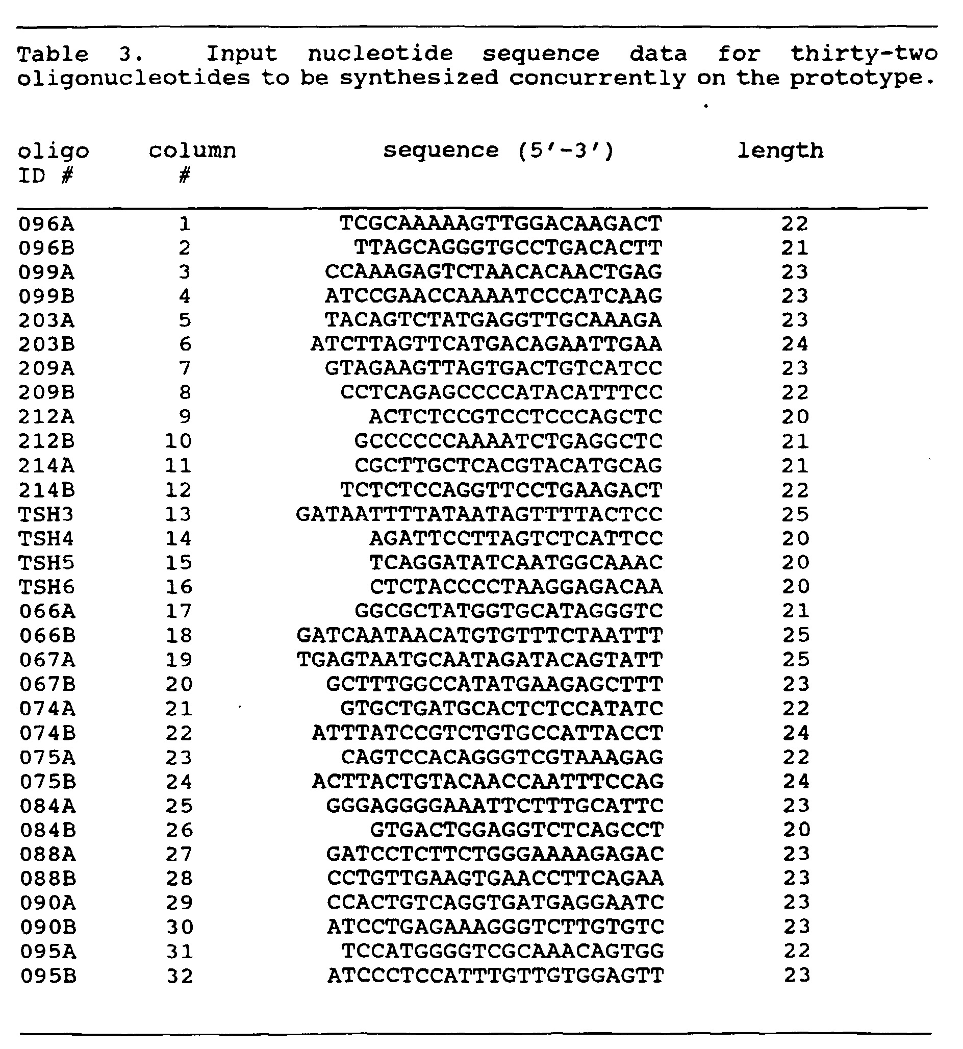
- To operate the process, in addition to the initialization of the reaction control center as outlined above, the initial set up process calls for the loading of each of the reagent chemicals into the proper reservoir in accordance with the scheme shown in Figure 3.
- An important aspect of the set up procedure is to load the columns to be coupled onto the
carrier tray 8. This is conveniently done on a work bench from which the carrier tray is moved for insertion into the reaction chamber where each column is positioned properly within its associated Luer fitting 15. The reaction chamber is sealed by fasteningplate 90 onto the front of thereaction chamber 10. It should be noted that the location of specific supports in specific columns to be coupled must be coordinated with the sequence data in the control center. In that manner, the addition of chemicals in the proper order will be made to the proper column in the proper sequence. For example, with reference to Table 3, columns containing the proper support corresponding to the 3' end of the Table 3 sequence are loaded into the carrier tray in the order shown. Therefore, columns containing T support are placed intopositions positions - Manual valves associated with the
gas supply tank 21 are opened so that the pressurized inert gas flows intoline 35 to pressurize each of the reservoirs. The gas also flows intoline 36 and to thereaction chamber 10 to flood the chamber with inert gas. A manual bleeder valve, not shown, for the reaction chamber may be opened during this operation so that all of the air in the chamber is displaced as the inert gas enters. If needed, valve V2 may be opened and valve V3 closed so that inert gas flows into the exit basin. - After the set up and initializing procedures are carried out, the apparatus is ready to begin the process of synthesizing oligonucleotides. The operation of the control program is shown in Figure 8 where the
first step 200 is to deblock all supports to be coupled. It should be observed that while 32 supports may be positioned within the prototype unit, the actual number of supports to be coupled may vary from 1 to 32 on any particular run. - The chemistry of synthesizing DNA is well known and therefore will not be explained in detail. The general object of the deblocking operation at
step 200 is to remove the 5' blocking elements from the derivatized nucleosides attached to the supports. Removal of the blocking elements enables the nucleosides to be reactive to the application of coupling reagents. - Once the deblocking step has been performed, the supply line is flushed and all of the deblocked supports are washed at
step 201. This step ensures that all of the deblocking chemical reagent has been removed prior to performing thenext step 202 which is the coupling of all supports requiring addition of the nucleotide reagent "A" which is the common designation for reagent containing the base "adenine". - After flushing and repriming the supply line, the
next step 203 in the inventive process is to couple all supports requiring the nucleotide reagent "C" which is the common designation for reagent containing the protected "cytosine" precursor. Atstep 204, after washing and repriming the supply line, coupling of all supports requiring the addition of nucleotide reagent "G" is carried out. G is the common designation of the nucleotide reagent containing the base "guanine." Similarly, atstep 205, coupling all supports requiring the base "T" is carried out. T is the common designation for the nucleotide reagent containing the base "thymine." It should be noted that operation of the inventive apparatus is herein exampled through the use of a specific coupling chemistry making use of the above named A, C, T and G nucleotide reagents. Collectively, these reagents are often referred to as "phosphoramidite" or "amidite" reagents to distinguish them from other currently known coupling chemistries such as the "phosphotriester" and "phosphonate" chemistries. The inventive apparatus, appropriately programmed, can be used with coupling chemistries other than the one chosen herein to exemplify the operation of the machine. - After the appropriate incubation period, vacuum is applied to remove the reagents from the columns to the waste reservoir. All of the coupled supports are washed at
step 206 to remove any unreacted A, C, G and T reagents. All of the coupled supports are oxidized atstep 207 and washed again atstep 208. A blocking compound is added to cap any nascent oligonucleotides that failed to couple atstep 209. The coupled supports are washed again atstep 210 and additional reagents added through the repetition ofsteps 200 through 210 to provide the next base in the sequence. When synthesis of the sequences shown in Table 3 has been completed, the query at step 211 results in a branch to step 212 for deblocking the supports and washing them atstep 213. The supports may then be removed from the reaction chamber to the work bench for final workup involving conventional deprotection. - Figures 9A-9B are a more detailed description of the procedure performed in carrying out each of the steps of the process shown in Figure 8. For example, when the deblocking step 200 (Figure 8) is entered, the detailed operations of step 250-263 are performed. The first operation as shown at
step 250 in Figure 9 is to set the number of times, n, that the deblocking reagent is to be added to each column in order to provide a total of 0.7 ml of the reagent. To do that, the control program makes reference to input data shown in Table 2, to ascertain the number of additions for the deblocking step. That data shows that the deblocking step takes four additions, that is, the supply line outlet must make four passes over the columns in order to provide the needed total volume (0.7 ml) of deblocking reagent to each column, each pass delivering 0.175 ml. Therefore, the control program sets the control parameter n to equal four atstep 250. Atstep 251 the reagentsupply line outlet 18 is moved to theflush column 12. Atstep 252, the appropriate valves are opened in order to prime thesupply line 33 with the deblocking reagent inreservoir 51. With reference to Figure 3,valve 66 is positioned to connectlines 33 and 33' andvalve 70 is actuated to connectreservoir 51 with line 33'. After flushing and priming thesupply line 33 with deblocking reagent,valve 70 is closed. Atstep 253, which is performed concurrently withstep 252, the valve V4 is operated to drain the flush column. - The column numbers to be coupled are read by the control program at
step 254 from input data such as Table 3 and theoutlet 18 is moved by the stepper motor to the first column to be coupled atstep 255. With reference to the example shown in Table 3, all 32 columns of the device are to be coupled. Oligo ID # 096A will be synthesized in the first column of the linear column array and oligo ID # 095B will be synthesized in the 32nd and last column of the array. As previously mentioned, the prototype device can operate to synthesize any number of oligonucleotides from one to 32, with input data such as Table 3 for any particular operation read into the computer system. In this example, since all 32 columns are in use,outlet 18 is first moved to the first column atstep 255. -
Valve 70 is opened atstep 256 for the period of time needed to provide the proper amount of deblocking reagent (.175 ml) to the first column. Thereafter,valve 70 is closed, and atstep 257 the query is asked whether the step has been completed for all columns to be coupled (in this instance, are all columns deblocked). Since at this point in the procedure the deblocking reagent has only been added to the first column, the answer is "no," and a return is made to repeatsteps 255 through 257 until all columns to be coupled have received .175 ml of deblocking reagent. After adding deblocking reagent to all appropriate columns (32 in this instance),reagent outlet 18 is moved to the flush column atstep 258 and atstep 259 the system waits until the incubation time needed for the deblocking reagent to unmask the 5' ends of the nascent oligonucleotides has been completed. Table 2 identifies that time as 15 seconds. - At
step 260, valve V3 is opened to apply a vacuum to the outlet end of all of the reaction columns to drain the deblocking reagent from the columns that are to be coupled. Valve V3 is then closed and valve V2 is opened atstep 261 to introduce argon into the vacuum chamber to equalize pressure on both the inlet and outlet ends of the columns. n is set equal to n - 1 atstep 262, which at this point in the deblocking operation results in setting n to 3. Atstep 263, the query is whether n is equal to 0, and since it is not, a return is made to repeatsteps 254 through 263 in order to add deblocking reagent for a second time to all of the columns to be coupled. - After a repetition of the
deblocking operation step 200 four times, n is equal to 0 and the query atstep 263 identifies that the deblocking operation has been completed. - When the washing step 201 (Figure 8) is initiated to clear the supply line and the reaction columns of remaining deblocking reagent, the procedure shown in Figures 9A and 9B is again carried out except that n is initially set to five at
step 250, as shown in Table 2, and atstep 252, the valve which is opened and closed is valve 71, as may be seen by reference to Figure 3. The flush column is drained atstep 253 and atstep 254, all columns to be coupled are identified. Steps 255-257 are performed until all columns to be coupled (32 in this case) contain the wash chemical. Steps 258-263 are performed to provide the proper incubation time (2 seconds), to drain the columns to equalize pressure above and below the frits and to reduce the value of n to 4. Steps 254-263 are repeated until five passes are completed and n = 0. - After the
wash process step 201 is completed, step 202 (Figure 8) is entered to couple all of the supports requiring the addition of reagent A. Again, the detailed procedure for carrying outstep 202 is shown in Figure 9. n, the number of additions for the coupling step, is set equal to 3 atstep 250, as shown by Table 2, andvalves step 252 to prime the supply line.Valve 66 is also operated to connect lines 33'' and 33. Note that in addition to the amidite reagent A, an activator is also introduced into the supply line together with the reagent A. This is preferably accomplished by rapidly opening and closingvalves step 252 to mix the amidite and the activator in the priming ofsupply line 33. The flush column is drained atstep 253 and the column numbers to be coupled with the amidite A are ascertained atstep 254 by referring to the sequence input data in Table 3. - Table 3 shows the sequence in which couplings are carried out. As described above, the 3' nucleotide is derived from a previously produced starter support which is placed in the appropriate column as part of the set-up procedure. Thus, the first couplings to be produced in the machine add the second base from the 3' end in Table 3. Therefore, the first addition of A is to the supports in
columns columns - With the input data identified, the
outlet 18 is moved atstep 255 to the next column to be coupled, that is, the first column to receive the addition of reagent A, column 3. Atstep 256, thevalves - At
step 257, a branch is made to step 255 for positioning theoutlet 18 at the next column to receive amidite A, that is,column 4. Step 256 is performed to add 0.1 ml of amidite A/activator tocolumn 4 after which the procedure ofsteps columns - At this point in the procedure the first pass for adding amidite A is completed and a branch is taken at
step 257 tosteps prime column 12 and the query of whether an amidite A, C, T or G has been added results in a branch to step 400. Atstep 400, one of three procedures is selected for continuing the operation. These three separate procedures are illustrative of the many variations which can be made in the processes which utilize the inventive apparatus without parting from the spirit and scope of the invention. For example, if procedure E1 is selected, the coupling steps are performed in the same manner that has already been explained above with reference to the deblocking and washing steps. If procedure E2 is selected, the procedure is a variation of the E1 procedure except that certain steps are skipped as explained below. If procedure E3 is selected, a considerably different alternative procedure will be performed as explained below. - In procedure E1 of Figure 9B, at
step 259, the incubation period for the amidite A (15 seconds) is completed, after which the coupled columns are drained atstep 260 and pressure is equalized atstep 261. Since the first pass of adding the amidite A is now completed, n is set to 2 atstep 262, and since n is not zero, a branch is made atstep 263 to step 255 for the second pass of adding amidite A. - After completion of the second pass, the process continues for a third and final pass after which the query at
step 263 results in a return to Figure 8,step 203, for adding the amidite C. - The procedure of E1 Figure 9B, explained above with reference to amidite A, is repeated for adding amidite C to those columns identified as requiring C. With reference to Table 3, those columns are identified by the control program as
columns step 206 calling for the washing of all coupled supports. - The process shown in Figures 9A and 9B is again carried out for the washing operation of
step 206 withvalve 60 opened in order that the supply line 33'' for the activator and amidite chemicals may be washed. After completion ofstep 206, the process shown in Figures 9A and 9B is performed again during the oxidizingstep 207 by activatingvalve 67 withvalve 66 operated to connectlines 33' and 33. Another wash step is performed atstep 208 involving valve 71 and then all of the coupled supports are capped atstep 209. In order to perform that step,valves supply line 33. The coupled supports are again washed atstep 210. - At this point in the synthesis procedure, all of the steps have been completed for coupling the first nucleotide reagent to each of the starter materials for the 32 sequences shown in Table 3. That is to say, if all couplings are successful, the support in
column 1 now has a C attached at the 5' end of the T already there; the support in column 2 has a T attached at the 5' end of the T already there; the support in column 3 has an A attached to the 5' end of the G; the support incolumn 23 has an A attached to the 5' end of the G, etc. Ideally, all the molecules produced in a particular column will be of the same length and the same nucleotide sequence. However, coupling efficiency is not perfect and some small percentage of the population of molecules may fail to couple. Any nascent oligonucleotide which failed to couple will be capped instep 209 and thus will not participate in subsequent coupling reactions. In that manner, the synthesis of shorter than full length sequences is precluded or minimized. - At step 211, the query of whether any further couplings are to be performed is answered in the affirmative since only the first coupling has been completed at this point. Table 3 shows that the particular synthesis under preparation is to provide oligonucleotide primers with base couplings ranging from 20 to 25 in length. Consequently, a branch is taken at step 211 to step 200 to repeat the entire process described above in order to add the second base coupling to each sequence. As shown in Table 3, during this part of the procedure, the support in
column 1 will receive an A; the support in column 2 will receive a C; the support in column 3 will receive a G and the support incolumn 32 will receive a G. - The process continues after completion of the second coupling until all bases have been added to each of the 32 columns. When all couplings are completed, the procedure of Figures 8 and 9 will have been performed 24 times. At this point, at step 211, the query of whether further couplings are to be performed is answered in the negative and a branch is taken to step 212.
-
Steps step 212, a deblocking (detritylation) reagent is added to all columns and, after deblocking, all columns are washed atstep 213. Thefront cover 90 is removed and the 32support columns 11 are removed from thereaction chamber 10.
- The results of an early run with the 32-place prototype are shown in Table 4, which shows the yields for each of the 32 oligonucleotides produced. Total yields were based on optical density measurements of purified oligonucleotide recovered from preparative gels, and show an average total yield of approximately 500 micrograms for each sequence. The run was completed in 6 hours, with consumption of reagents during the run only about one-quarter of that to produce a similar sequence in a prior art commercial single column synthesizer even though no serious attempt was made to optimize reagent usage in the prototype. In addition to economy in reagent consumption, the time required to synthesize 32 oligonucleotides using the prototype synthesizer, is markedly less than that required by prior art single column or four column synthesizers. The innovative principals of operation embodied in the prototype, that is the "open" flow path with the inlet of each column to be coupled opened to the atmosphere of the reaction chamber, the motion controlled reagent outlet, which can move from support to support, the exit basin coupled to each of the multiple columns, and the controlled atmosphere of the chamber make it possible to further increase the concurrent production of oligonucleotide primers by simply increasing the number of columns in the device, either by adding columns to the linear array or by providing a two dimensional array of columns. Changes in hardware and software to accommodate additional columns beyond 32 are minimal, which is in sharp contrast to prior art systems. Such systems are tightly plumbed from the reagent supply system to all of the individual columns making the addition of columns a difficult matter.
- One of the advantages of the inventive process described herein is that a single priming of the delivery line is all that is necessary for each amidite added during a cycle. As priming consumes significant quantities of reagent, the saving in reagent consumption is significant compared to prior art devices which have delivery lines to each column. As larger and larger numbers of oligonucleotides are prepared concurrently, the advantages of the inventive process become even more important. The effective change over of reagents during the various steps improves reagent economy, but the removal of reagents through the application of vacuum is also a significant improvement leading to economy in the amount of reagent needed. As the vacuum draws off the reagent, the column is dried thus providing more efficient use of the next reagent.
- Use of the open flow path currently requires a sealed reaction chamber so that the atmosphere within the chamber can be controlled. While it might be possible to synthesize DNA without maintaining a controlled atmosphere, yields would suffer because the chemistry is very sensitive to moisture. Should a chemistry be developed that is not sensitive to moisture, it would be possible to operate the instrument in ambient conditions.
- It should be noted that a balance is achieved between the forces which retain the reagent solutions in the columns, that is, forces such as surface tension and capillarity, and those forces which cause the reagents to flow out of the columns, that is, forces such as gravity and pressure differentials. By providing the balance, the reagent chemicals are allowed to saturate the column during the incubation period, but are drawn off quickly and uniformly from all columns when a pressure differential is applied.
- As mentioned above, the inventive apparatus may be operated in several fashions to produce the synthesis; flexibility is a feature of the automated apparatus. To illustrate, at
step 400, one of three procedures could be selected. The procedure according to the branch E1 was selected and explained above. However, should the user of the apparatus have selected the procedure E2, a branch would be made to Figure 9C. The first entry into procedure E2 is when the first pass for adding amidite A is completed and the movable outlet has been moved to its home position over the flush/prime column 12. Atstep 258A, the query of whether an amidite A, C, T or G has been added, has resulted in a branch to step 400 where the procedure E2 was selected. Since n was set equal to 3 atstep 250 to provide for three additions of amidite A, and since one pass is now complete, n is set to two at step 258B. Since n is not zero, a branch is made atstep 258C to step 258D to wait for completion of the 15 second incubation period after which return is made to step 255 for the second pass of adding amidite A. - Note that in this variation of the procedure, a return is made to step 255 without first draining all the coupled columns and equalizing pressure above and below the frits. These steps can be skipped if the porosity of the frits are such that the reagent has substantially drained away from the support during the 15 second incubation period.
- The process continues as previously described for the second pass of adding the amidite A and continues for a third and final pass after which the query at
step 258C results in a branch to step 258F to wait for the incubation period. When the period is complete, all the coupled columns are drained atstep 258G and pressure above and below the frits is equalized atstep 258H. At this point in the procedure only amidite A has been added and therefore a return is made to the next major step of the process as shown in Figure 8,step 203, for adding the amidite C. - The procedure of Figure 9 with the E2 variation shown in Figure 9C selected, is repeated for adding the amidite C to those columns identified as requiring C as previously described with reference to Table 3. Those columns are identified by the control program as
columns step 206, calling for the washing of all supports. - The inventive apparatus may also be operated to produce faster turnaround at the expense of using some additional reagent chemicals by altering the control program as shown in Figure 10 through the selection of E3 at
step 400. In this version, at the conclusion of the first of the three passes for a coupling step adding the first reagent, for example, A, to the designated columns, the supply line is flushed and primed with the next reagent, for example, C. The operation proceeds to add reagent C without waiting for the conclusion of the relatively long incubation period of 15 seconds. After adding reagent C, the next reagents T and G are added as required after which the process waits for a single incubation period of 15 seconds. All coupled columns are then drained simultaneously. The process then repeats two more times to achieve the three passes indicated for a completed coupling step. While this alternative uses more reagent than the E1 and E2 processes shown in Figures 9B and 9C, it will still use considerably less reagent than prior art systems which primed individual lines for each column. As the number of columns increase, the advantage of the inventive system becomes greater and greater. The alternative process of Figure 10 is superior to the processes shown in Figures 9B and 9C in a time sense since the number of relatively long 15 second incubation time periods during which the machine is in a wait state is greatly reduced. - To perform the method of Figure 10, the initial set up procedure is the same as described above and the first two steps shown in Figure 8,
steps step 202 in Figure 8, the control program first determines whether the reagent A is to be added. In the example synthesis of Table 3, A is required and therefore step 202 to add reagent A is performed. As previously described, the steps 250-258A, shown in Figures 9A and 9B, are performed to complete a first pass of adding A to all supports requiring that reagent. The query atstep 258A results in a branch to step 400 and to E3 in Figure 10 in the alternative procedure. - In Figure 10,
step 300, a determination is made that the reagent A has been added. This determination is made within the control program which calls for the addition of A atstep 202, if required, and the input data of Table 3, which has required the addition of A. Alternatively, this determination could be performed by feedback from the process apparatus. Atstep 301, the input data of Table 3 is inspected to determine whether the addition of reagent C is required. Since it is, the supply line is flushed of A and primed with C at step 302 following which steps 255-257 are repeated until an addition of nucleotide reagent C has been made to all columns requiring that reagent. The query atstep 257 then results in a branch to step 258 for moving the supply line to the flush/prime column, and a branch is again taken to E3 in Figure 10. - Step 300 results in a branch to step 303 since A was not added on this loop through the procedure. At
step 303, the control program notes that the reagent C has been added. Next, the input data of Table 3 is reviewed atstep 304 to determine whether the reagent G should be added. Since the input data includes G, the supply line is flushed of C and primed with G atstep 305. Steps 255-257 are again repeated until the addition of G has been made to all columns requiring that reagent.Steps - Since neither A nor C was added on this loop through the procedure, steps 300 and 303 are negative determinations but since G has been added,
step 306 results in a branch to step 307 to determine whether reagent T is required. The input data of Table 3 is reviewed and since the reagent T is to be added, the supply line is flushed of G and primed with T atstep 308. Steps 255-257 are again performed to add T to all supports requiring that reagent.Steps -
Steps step 312 and pressure differentials above and below the frits are equalized atstep 313. - The control parameter, n, is changed to 2 at
step 314 signifying, in this instance, that a completed first pass has been made for all reagents to be added. Since n is not zero, a branch is made atstep 315 to step 316 to inquire whether the reagent A is to be added. Since the input data of Table 3 require A, the supply line is flushed of T and primed with A atstep 317. A return is made to perform steps 255-257 until all supports requiring reagent A have received an addition.Steps - The process continues as described above until all required coupling reagents have been added, that is, all couplings for the synthesis process corresponding to the input data in Table 3 have been completed. At this point, step 315 results in a branch to step 206, Figure 8, to wash all of the coupled supports. The process is completed through all remaining steps as previously described.
- As mentioned above, the inventive apparatus and procedure is of value in many situations requiring fast, economical production of large numbers of DNA (or RNA) oligonucleotides. For example, one such situation is in molecular genetic research where synthetic DNA's are used as primers in DNA sequencing by the dideoxy method. One strategy for obtaining long sequences by the dideoxy method is that of "primer-walking." In this strategy, a long template is prepared and sequencing is initiated from one end. The sequence is read as far as possible and a new primer is chemically synthesized based on sequence near the end of the first "read." The new primer is used to initiate a second round of sequencing thereby extending the initial sequence. Repetition of the process generates a long contiguous sequence which is limited, in principal, only by the length of the template. However, each step in the walking process requires synthesis of a new template-specific primer.
- Parallel dideoxy sequencing of multiple long templates by a primer-walking strategy has the potential of dramatically accelerating the acquisition of sequence data by reducing the labor and expense associated with preparation of large numbers of short templates and also by reducing the effort involved in reassembling long contiguous sequences. Cost effective implementation of the parallel primer-walking approach for large scale sequencing projects is made practical by this invention.
- The specific prototype of Figures 2-7 described has one row of columns and one supply line outlet. A two dimensional array of columns is shown in Figure 1B and an outlet capable of two dimensional motion is provided for use with that array. Also, if desired, the apparatus could have more than one movable outlet and more than one flush/prime column. In that manner, during the 15 second incubation period for amidite A, the second outlet could supply amidite C, for example; or, the second outlet could serve an entirely different group of columns. The prototype does not include sensing devices to provide feedback data for closed loop operation. That type of operation has not been needed to date, but obviously such control could be added to the instrument, for example, if the device is built to have 100 or more columns, feedback control might become desirable.
- In the above-described procedure as it relates to the prototype machine of Figures 2-7, setting up the machine requires the use of columns containing the proper support corresponding to the 3' end of the Table 3 sequence loaded into the carrier plate in a manner that is coordinated with the sequence data in the control center. Therefore, columns containing the T support are placed into
positions positions - Various support materials and various chemistries are known for producing derivatized supports. Polymeric supports, silica gel supports, cellulose and others are known as well as controlled pore glass (CPG). It is visualized that the inventive apparatus can be used for directly derivatizing these various supports. With respect to Figures 1B and 1C, the support material may be a porous frit-like material suitable for direct derivatization. The appropriate derivatization chemicals are placed in the reservoirs of Figure 3 so that
supply line 33 can contain the appropriate reagent in the sequence of the derivatization operation. A control program to operate the valves and to moveoutlet 18 must be provided together with input information providing the amount of reagent to be added, the number of additions and the incubation periods. Once the supports have been derivatized and washed, the synthesizing process described above can then be performed without incurring the danger of a manually misplaced support. - The instrument can be used, if desired, for the production of derivatized supports in a
carrier plate 8 as shown in Figure 1B without thereafter directly proceeding to the synthesizing process. In that manner, a number of derivatized supports can be accumulated for subsequent synthesizing operations. - While the invention has been described above with respect to specific embodiments, such as, for example, the particular control program format, it will be understood by those skilled in the art that various changes in form and detail may be made therein without departing from the scope of the invention. The invention has been described with a vacuum source to apply a pressure differential between the inlet and outlet ends of the reactive columns, but it is within the broad spirit and scope of the invention to provide a pressure differential by any appropriate measure. Also, while the production of primer length oligonucleotides is currently visualized as a major use of the apparatus, much longer oligonucleotides can be produced if desired. The invention receives definition in the following claims.
Claims (23)
- Apparatus for automating processes including the synthesis of oligonucleotides comprising:a supply system including reservoirs of individual reagent chemicals, valves and an output supply line, said valves connected to said reservoirs and to said supply line such that said supply line can be filled with any one or more of said chemicals;a reaction chamber containing an outlet of said supply line;a reaction column located within said reaction chamber with an inlet end of said reaction column within said reaction chamber;a flush/prime column located within said reaction chamber, an inlet end of said flush/prime column of said reaction chamber; andmotive means for moving said outlet of said supply line from a first position adjacent said inlet end of said flush/prime column to a position adjacent said inlet end of said reaction column.
- The apparatus of claim 1 further including pressure means connected to said reaction chamber for providing an equalized pressure between the inlet and outlet ends of said reaction column to enable an incubation time period in said reaction column for reagent chemical additions, and for providing a pressure differential between said inlet and outlet ends of said reaction column to drain said reaction column upon completion of said incubation time period.
- The apparatus of claim 1 further including at least one additional reaction column thereby providing said apparatus with a plurality of reaction columns, each reaction column having an inlet end open to the atmosphere of said reaction chamber, said motive means for moving said outlet of said supply line to a position adjacent the inlet end of each of said plurality of reaction columns.
- The apparatus of claim 3 further including control means connected to said motive means for positioning said outlet of said supply line over a selected one of said plurality of reaction columns; andfurther including exit means located adjacent to and sealed from said reaction chanter for connection with an outlet end of each of said plurality of reaction columns; andfurther including pressure means connected to said reaction chamber and to said exit means for providing an equalized pressure between the inlet and outlet ends of said plurality of reaction columns to enable an incubation time period in said plurality of reaction columns for reagent chemical additions, and for providing a pressure differential between said inlet and outlet ends of said plurality of reaction columns to drain said plurality of reaction columns upon completion of said incubation time period.
- The apparatus of claim 4 further including a movable carrier plate means for insertion into and removal from said reaction chamber, said movable carrier plate means for holding said plurality of reaction columns, and upon assembly with said apparatus for sealing said reaction chamber from said exit means in a manner that permits atmospheric communication between said reaction chamber and said exit means only through said plurality of reaction columns.
- The apparatus of claim 5 wherein said movable carrier plate means is assembled into said apparatus for derivatizing reaction support material within said plurality of reaction columns and, after derivatization, for continuing with an oligonucleotide synthesis process without removing said movable carrier plate from assembly with said apparatus, and
wherein each of said reaction columns is comprised of a porous means for sustaining said reagent chemicals when applied to said plurality of reaction columns and for allowing said reagent chemicals to pass through to said exit means upon application of said pressure differential. - The apparatus of claim 4 wherein said pressure means includes a vacuum source and said exit means includes an exit basin, said exit basin connected between said vacuum source and the outlet ends of said plurality of reaction columns whereby vacuum pressure is applied to all reaction columns simultaneously, andfurther including a source of inert gas connected to said reaction chamber to fill said reaction chamber with said inert gas, said reaction chamber sealed to the surrounding atmosphere, andfurther including a gas line for connecting said source of inert gas to said exit basin, whereby said exit basin is filled with said inert gas, a first valve for controlling the flow of inert gas to said exit basin and a second valve for connecting said exit basin to said vacuum source, whereby said exit basin is filled with inert gas prior to the application of reagent chemicals to said reaction columns through opening said first valve with said second valve closed, and whereby said exit basin is connected to said vacuum source to remove reagent chemicals from said plurality of reaction columns by opening said second valve with said first valve closed, wherein each of said reaction columns is comprised of a porous means for sustaining said reagent chemicals when applied to said reaction columns and for allowing said chemicals to pass through to said exit means upon application of said pressure differential, andfurther including a processor means and a control program, said processor means connected to random access memory and to one or more disk and diskette drives for holding and operating said control program and for holding input data, said processor means connected to said control means for controlling said motive means, said processor means also connected to said valves, whereby said processor means operates said control program to control all aspects of the process of reagent addition to said plurality of reaction columns and the evacuation of said plurality of reaction columns after completion of said incubation period, andfurther including a display and manual input means whereby a user can adjust or replace said control program and said input data as needed.
- A method of synthesizing oligonucleotides comprising the steps of:providing the apparatus of claim 5, wherein said movable carrier plate means includes a first and second carrier plate;providing the first carrier plate with said plurality of reaction columns containing derivatized supports;locating said first carrier plate within said reaction chamber;in a first operational run, synthesizing oligonucleotides in those reaction columns to be coupled, said run under the control of a computerized reaction control center,during said first operational run, preparing said second carrier plate with a second plurality of reaction columns containing derivatized supports;removing the first carrier plate from said apparatus at the conclusion of said first operational run; andlocating said second carrier plate within said reaction chamber in order to begin a second operational run after the completion of said first run.
- The apparatus of claim 4 wherein each said reaction column includes a reaction support for producing oligonucleotides of the same or different length, said reagent chemicals including a deblocking chemical, a wash chemical, an oxidizing chemical, a capping chemical and coupling chemicals, said control means further including:means for controlling the deblocking of all supports to be coupled through the addition of deblocking chemical to each support to be coupled;means for controlling the application of a pressure differential between the inlet end the outlet end of each support to draw deblocking chemical from each support;means for controlling the removal of said pressure differential on the inlet and outlet ends of said supports;means for controlling the washing of all deblocked supports through the application of an appropriate wash chemical to each support;means for controlling the application of a pressure differential between the inlet end and the outlet end of each support to draw said wash chemical from each support;means for controlling the coupling of all supports to be coupled through the addition of an appropriate reagent coupling chemical to said supports to be coupled;means for controlling the application of a pressure differential between the inlet end and the outlet end of each support to draw said reagent coupling chemical from said supports;means for controlling the washing of all coupled supports through the application of an appropriate wash chemical to each said support;means for controlling the oxidation of all coupled supports through the addition of an appropriate oxidizing chemical to each said support;means for controlling the application of a pressure differential between the inlet ends and the outlet ends of said supports to draw said oxidizing chemical from each said support;means for controlling the washing of all oxidized supports through the application of an appropriate wash chemical to each said support;means for controlling the capping of all coupled supports through the application of an appropriate capping chemical to each of said coupled supports;means for controlling the application of a pressure differential between the inlet end and the outlet end of said supports to draw said capping chemical from each said support;means for controlling the washing of all capped supports through the application of an appropriate wash chemical to each said support;wherein said means for controlling the coupling of all supports further comprises:first means for controlling the coupling of all supports requiring a first reagent chemical, for example A;second means for controlling the coupling of all supports requiring a second reagent chemical, for example C;third means for controlling the coupling of all supports requiring a third reagent chemical, for example G; andfourth means for controlling the coupling of all supports requiring a fourth reagent chemical, for example T; andmeans of sequentially controlling the operation of said first, second, third and fourth means for adding said first coupling reagent to all columns requiring that reagent before adding said second, third or fourth reagents to columns requiring those reagents.
- The apparatus of claim 9 wherein said means for controlling the coupling of said supports includes means for controlling the application of a multiple number of additions of each reagent to each support requiring that reagent;wherein said means for controlling the coupling of said supports includes:activation means energized between the coupling of supports with different reagents for initiating the movement of the outlet of the supply line to the inlet of a flush column;means for controlling the washing of said supply line by application of an appropriate wash chemical; andmeans for controlling the priming of said supply line with the next coupling reagent.
- A method of operating apparatus for synthesizing oligonucleotides wherein said apparatus includes a supply system with a plurality of reagents, multiple reaction supports for producing oligonucleotides of the same or different lengths in a concurrent manner, and a movable reagent outlet for supplying said plurality of reagents to said supports by moving from support to support, including the steps of:deblocking all supports to be coupled through the addition of deblocking chemical to each support;applying a pressure differential between the inlet and the outlet end of each support to draw deblocking chemical from each support;removing said pressure differential and equalizing pressure on the inlet and outlet ends of said supports;washing all deblocked supports through the application of an appropriate wash chemical to each support;applying a pressure differential between the inlet end and the outlet end of each support to draw said wash chemical from each support;removing said pressure differential and equalizing pressure on the inlet and outlet ends of said supports;coupling all supports to be coupled through the addition of an appropriate reagent coupling chemical to said supports;applying a pressure differential between the inlet end and the outlet end of each support to draw said reagent coupling chemical from said supports;removing said pressure differential and equalizing pressure on the inlet and outlet ends of such supports;washing all coupled supports through the application of an appropriate wash chemical to each said support;applying pressure differential between the inlet end and the outlet end of said supports to draw said wash chemical from said supports;removing said pressure differential and equalizing pressure on the inlet and outlet ends of said supports;oxidizing all coupled supports through the addition of an appropriate oxidizing chemical to each said support;applying a pressure differential between the inlet end and the outlet end of said supports to draw said oxidizing chemical from each said support;removing said pressure differential and equalizing pressure on the inlet and outlet ends of said supports;washing all coupled supports through the application of an appropriate wash chemical to each said support;applying a pressure differential between the inlet end and the outlet end of said supports to draw said wash chemical from each said support;removing said pressure differential and equalizing pressure on the inlet and outlet ends of said supports;capping all coupled supports through the application of an appropriate capping chemical to each of said coupled supports;applying a pressure differential between the inlet end and the outlet end of said supports to draw said capping chemical from each said support;removing said pressure differential and equalizing pressure on the inlet and outlet ends of said supports;washing all coupled supports through the application of an appropriate wash chemical to each said support;applying a pressure differential between the inlet end and the outlet end of said supports to draw said wash chemical from each said support;removing said pressure differential and equalizing pressure on the inlet and outlet ends of said supports; andwherein said step of coupling all supports comprises the steps of:first coupling all supports requiring a first reagent chemical, for example A; thencoupling all supports requiring a second reagent chemical, for example C; thencoupling all supports requiring a third reagent chemical, for example G; thencoupling all supports requiring a fourth reagent chemical, for example T.
- The method of claim 11 wherein each step of coupling requires a multiple number of additions of each reagent to each support requiring that reagent;wherein a single addition of all coupling reagents is performed prior to waiting for an incubation period, andwherein between each step of coupling a different reagent chemical, the following steps are carried out:moving the outlet of the supply line for reagent chemicals to the inlet of a flush column; andwashing said supply line by application of an appropriate wash chemical, then proving said supply line with the next coupling reagent.
- An automated method for synthesizing oligonucleotides making use of apparatus that includes a supply system with a plurality of reagents such as the phosphoramidite bases A, C, T, and G, deblocking chemicals, wash chemicals, capping chemicals and oxidizing chemicals, multiple reaction columns each with an inlet end open to the atmosphere of a reaction chamber and an outlet end, at least one of said reaction columns having a support for producing an oligonucleotide, means for applying and removing a pressure differential across said reaction columns to drain said columns, at least one supply outlet located within said reaction chamber, said outlet connected to a supply line for delivering from said supply system to said reaction columns by aligning the position of said supply outlet and the inlet end of a selected reaction column, said apparatus controlled by a control system including means for selecting which reaction column is to be aligned with said supply outlet, for controlling the alignment of the selected reaction column and supply outlet, and controlling the addition and removal of the reagents and chemicals in the selected reaction column, said method including the machine-implemented steps of:deblocking supports to be coupled by aligning the supply outlet and the inlet end of each selected reaction column having such a support and thereupon supplying deblocking chemical to each such column;applying a first pressure differential between the inlet end and the outlet end of each reaction column to remove deblocking chemical from each support to be coupled;removing said first pressure differential and equalizing pressure on the inlet and outlet ends of said reaction columns;washing deblocked supports by aligning the supply outlet and the inlet end of each reaction column having such a support and thereupon supplying an appropriate wash chemical to each such reaction column;applying a second pressure differential between the inlet end and the outlet end of each reaction column to remove said wash chemical from each support to be coupled;removing said second pressure differential and equalizing pressure on the inlet and outlet ends of said reaction columns;coupling supports to be coupled by aligning the supply outlet and the inlet end of each reaction column having such a support and thereupon supplying an appropriate reagent coupling chemical to such reaction columns;applying a third pressure differential between the inlet end and the outlet end of each reaction column to remove said reagent coupling chemical from each coupled support;washing coupled supports by aligning the supply outlet and the inlet end of each reaction column having a coupled support and thereupon supplying an appropriate wash chemical to each such reaction column;applying a fourth pressure differential between the inlet end and the outlet end of each reaction column to remove said wash chemical from said coupled supports;removing said fourth pressure differential and equalizing pressure on the inlet and outlet ends of said reaction columns;oxidizing coupled supports by aligning the supply outlet and the inlet end of each reaction column having a coupled support and thereupon supplying an appropriate oxidizing chemical to each reaction column having a coupled support;applying a fifth pressure differential between the inlet end and the outlet end of each reaction column to remove said oxidizing chemical from each oxidized support;removing said fifth pressure differential and equalizing pressure on the inlet and outlet ends of said reaction columns;washing oxidized supports by aligning the supply outlet and the inlet end of each reaction column having an oxidized support and thereupon supplying an appropriate wash chemical to each such reaction column;applying a sixth pressure differential between the inlet end and the outlet end of each reaction column to remove said wash chemical from each oxidized support;removing said sixth pressure differential and equalizing pressure on the inlet and outlet ends of said reaction columns;capping oxidized supports by aligning the supply outlet and the inlet end of each reaction column having a coupled support and thereupon supplying an appropriate capping chemical to each such reaction column;applying a seventh pressure differential between the inlet end and the outlet end of each reaction column to remove said capping chemical from each capped support;removing said seventh pressure differential and equalizing pressure on the inlet and outlet ends of said reaction columns;washing capped supports by aligning the supply outlet and the inlet end of each reaction column having a capped support and thereupon supplying an appropriate wash chemical to each such reaction column;applying an eighth pressure differential between the inlet end and the outlet end of said reaction columns to remove said wash chemical from each such reaction column having a capped support;removing said eighth pressure differential and equalizing pressure on the inlet and outlet ends of said reaction columns.
- The method of claim 13 wherein each step of coupling requires a multiple number of additions of each reagent to each support requiring that reagent, and wherein each step of coupling further includes waiting for an incubation period after a single addition to all supports requiring that reagent is complete.
- The method of claim 14, wherein said apparatus includes a flush/prime column having an inlet end open to the atmosphere of said reaction chamber and an outlet end, and wherein between each step of coupling a different reagent chemical, the following steps are carried out:aligning the supply outlet to the inlet end of said flush/prime column; andwashing said supply line by application of an appropriate wash chemical, then priming said supply line with the next coupling reagent.
- The method of claim 13 wherein each step of coupling requires a multiple number of additions of each reagent to each support, and wherein a single addition of all coupling reagents is performed prior to waiting for an incubation period.
- The method of claim 16, wherein said apparatus includes a flush/prime column having an inlet end open to the atmosphere of said reaction chamber and an outlet end, and wherein between each step of coupling a different reagent chemical, the following steps are carried out:aligning the supply outlet to the inlet of said flush/prime column; andwashing said supply line by application of an appropriate wash chemical, then priming said supply line with the next coupling reagent.
- A control system for controlling the synthesis of oligonucleotides through the use of apparatus that includes a supply system with a plurality of reservoirs holding deblocking chemicals, wash chemicals, capping chemicals and oxidizing chemicals as well as reservoirs containing the four phosphoramidite reagents A, C, T, and G, said apparatus having a reaction chamber holding a plurality of reaction columns each with an inlet end open to the atmosphere of said reaction chamber and an outlet end, at least one of said reaction columns having a support for producing an oligonucleotide, at least one supply system outlet located within said reaction chamber, said outlet connected to a supply line for delivering from said supply system to said reaction columns by aligning the position of said supply outlet and the inlet end of a selected reaction column, said control system including:means for providing signals for selecting which reaction column is to be aligned with said supply outlet;means for providing signals for controlling the alignment of said supply outlet and the selected reaction column;means for providing signals for controlling the amount of reagents and chemicals added to the selected reaction column;means for providing signals for deblocking all supports to be coupled by aligning the supply outlet and the inlet end of each selected reaction column having such a support and thereupon supplying deblocking chemical to each such column;means for providing signals for washing deblocked supports by aligning the supply outlet and the inlet end of each reaction column having such a support and thereupon supplying an appropriate wash chemical to each such reaction column;means for providing signals for coupling supports to be coupled by aligning the supply outlet and the inlet end of each reaction column having such a support and thereupon supplying an appropriate reagent coupling chemical to each such reaction column;means for providing signals for washing coupled supports by aligning the supply outlet and the inlet end of each reaction column having a coupled support and thereupon supplying an appropriate wash chemical to each such reaction column;means for providing signals for oxidizing coupled supports by aligning the supply outlet and the inlet end of each reaction column having a coupled support and thereupon supplying an appropriate oxidizing chemical to each reaction column having a coupled support;means for providing signals for washing oxidized supports by aligning the supply outlet and the inlet end of each reaction column having an oxidized support and thereupon supplying an appropriate wash chemical to each such reaction column;means for providing signals for capping oxidized supports by aligning the supply outlet and the inlet end of each reaction column having a coupled support and thereupon supplying an appropriate capping chemical to each such reaction column;means for providing signals for washing capped supports by aligning the supply outlet and the inlet end of each reaction column having a capped support and thereupon supplying an appropriate wash chemical to each such reaction column;
- The control system of claim 18 further including means for providing signals to allow the first incubation period for a coupling reagent after the completion of a single addition of that coupling reagent to all coupled supports requiring that reagent.
- The control system of claim 18 wherein said apparatus includes a flush/prime column having an inlet end open to the atmosphere of said reaction chamber, said control system further including:means for providing signals to align said flush/prime column and the supply outlet, andmeans for providing signals to wash the supply line.
- The control system of claim 18 further including:means for providing signals to allow the first incubation period for a coupling reagent after the completion of a single addition of all coupling reagents is complete.
- The control system of claim 18 wherein said apparatus includes means for applying and removing a pressure differential between the inlet end and the outlet end of said reaction columns, said control system further including:means for providing signals for applying and removing and said pressure differential.
- The control system of claim 18 further including:means for providing signals sequencing the delivery of the four reagents A, C, T, and G, such that each reagent is supplied to all reaction columns requiring that reagent before the next reagent is added to the reaction columns.
Applications Claiming Priority (3)
| Application Number | Priority Date | Filing Date | Title |
|---|---|---|---|
| US08/016,739 US5368823A (en) | 1993-02-11 | 1993-02-11 | Automated synthesis of oligonucleotides |
| US16739 | 1993-02-11 | ||
| PCT/US1994/001271 WO1994018226A1 (en) | 1993-02-11 | 1994-02-04 | Automated synthesis of oligonucleotides |
Publications (3)
| Publication Number | Publication Date |
|---|---|
| EP0683790A1 EP0683790A1 (en) | 1995-11-29 |
| EP0683790A4 EP0683790A4 (en) | 1996-03-13 |
| EP0683790B1 true EP0683790B1 (en) | 2000-04-26 |
Family
ID=21778699
Family Applications (1)
| Application Number | Title | Priority Date | Filing Date |
|---|---|---|---|
| EP94907420A Expired - Lifetime EP0683790B1 (en) | 1993-02-11 | 1994-02-04 | Automated synthesis of oligonucleotides |
Country Status (5)
| Country | Link |
|---|---|
| US (2) | US5368823A (en) |
| EP (1) | EP0683790B1 (en) |
| JP (1) | JPH08506813A (en) |
| DE (1) | DE69424151T2 (en) |
| WO (1) | WO1994018226A1 (en) |
Cited By (1)
| Publication number | Priority date | Publication date | Assignee | Title |
|---|---|---|---|---|
| US8357490B2 (en) | 2008-01-23 | 2013-01-22 | Roche Diagnostics Operations, Inc. | Integrated instrument performing synthesis and amplification, and a system and method thereof |
Families Citing this family (109)
| Publication number | Priority date | Publication date | Assignee | Title |
|---|---|---|---|---|
| EP1382386A3 (en) * | 1992-02-19 | 2004-12-01 | The Public Health Research Institute Of The City Of New York, Inc. | Novel oligonucleotide arrays and their use for sorting, isolating, sequencing, and manipulating nucleic acids |
| US5472672A (en) * | 1993-10-22 | 1995-12-05 | The Board Of Trustees Of The Leland Stanford Junior University | Apparatus and method for polymer synthesis using arrays |
| US6558633B1 (en) | 1994-09-21 | 2003-05-06 | Isis Pharmaceuticals, Inc. | Chemical reaction apparatus and methods |
| US5585069A (en) * | 1994-11-10 | 1996-12-17 | David Sarnoff Research Center, Inc. | Partitioned microelectronic and fluidic device array for clinical diagnostics and chemical synthesis |
| US5614608A (en) * | 1995-01-20 | 1997-03-25 | Selectide Corporation | Apparatus and method for multiple synthesis of organic compounds on polymer support |
| US5959098A (en) | 1996-04-17 | 1999-09-28 | Affymetrix, Inc. | Substrate preparation process |
| US5641459A (en) * | 1995-08-17 | 1997-06-24 | Pharmacia Biotech Ab | Machine for synthesizing oligonucleotides |
| US5888830A (en) * | 1995-09-22 | 1999-03-30 | Berlex Laboratories, Inc. | Apparatus and process for multiple chemical reactions |
| AU723605B2 (en) * | 1995-09-22 | 2000-08-31 | Berlex Laboratories, Inc. | Apparatus and process for multiple chemical reactions |
| CA2198433A1 (en) * | 1996-03-22 | 1997-09-23 | Sheila Helen Hobbs Dewitt | Information management system for automated multiple simultaneous synthesis |
| US6706875B1 (en) * | 1996-04-17 | 2004-03-16 | Affyemtrix, Inc. | Substrate preparation process |
| US5733509A (en) * | 1996-04-17 | 1998-03-31 | Motorola, Inc. | Method and system for synthesizing oligonucleotides using nucleotide-specific dispensing bars |
| AU4062597A (en) * | 1996-08-12 | 1998-03-06 | Monsanto Company | Solid phase organic synthesis device with pressure-regulated manifold |
| US5792430A (en) * | 1996-08-12 | 1998-08-11 | Monsanto Company | Solid phase organic synthesis device with pressure-regulated manifold |
| US6274094B1 (en) | 1997-01-13 | 2001-08-14 | Weller, Iii Harold Norris | Nestable, modular apparatus for synthesis of multiple organic compounds |
| JP2001511794A (en) * | 1997-02-17 | 2001-08-14 | ゲゼルシャフト・フュア・ビオテヒノロジッシェ・フォルシュング・エムベーハー(ゲー・ベー・エフ) | Automatic chemical synthesis equipment |
| US6126904A (en) * | 1997-03-07 | 2000-10-03 | Argonaut Technologies, Inc. | Apparatus and methods for the preparation of chemical compounds |
| US5961925A (en) | 1997-09-22 | 1999-10-05 | Bristol-Myers Squibb Company | Apparatus for synthesis of multiple organic compounds with pinch valve block |
| CA2253164A1 (en) * | 1997-11-14 | 1999-05-14 | Edward Michael Sioma | Apparatus and method used in multiple, simultaneous synthesis of general compounds |
| US6270730B1 (en) * | 1998-06-16 | 2001-08-07 | Northwest Engineering Inc. | Multi-well rotary synthesizer |
| US6455316B1 (en) | 1998-08-13 | 2002-09-24 | Symyx Technologies, Inc. | Parallel reactor with internal sensing and method of using same |
| US6306658B1 (en) * | 1998-08-13 | 2001-10-23 | Symyx Technologies | Parallel reactor with internal sensing |
| US6787112B1 (en) | 1998-08-13 | 2004-09-07 | Symyx Technologies, Inc. | Parallel reactor with internal sensing and method of using same |
| US6528026B2 (en) | 1998-08-13 | 2003-03-04 | Symyx Technologies, Inc. | Multi-temperature modular reactor and method of using same |
| US6548026B1 (en) | 1998-08-13 | 2003-04-15 | Symyx Technologies, Inc. | Parallel reactor with internal sensing and method of using same |
| DE19940752A1 (en) | 1998-08-28 | 2000-04-27 | Febit Ferrarius Biotech Gmbh | Use of an illumination matrix that can be controlled to generate a freely adjustable illumination pattern to produce a microchip |
| JP4569850B2 (en) * | 1998-09-24 | 2010-10-27 | 株式会社島津製作所 | Automatic synthesizer |
| US6258323B1 (en) | 1998-11-16 | 2001-07-10 | Rohm And Haas Company | Apparatus and method used in multiple, simultaneous synthesis of general compounds |
| US6309828B1 (en) | 1998-11-18 | 2001-10-30 | Agilent Technologies, Inc. | Method and apparatus for fabricating replicate arrays of nucleic acid molecules |
| US6264891B1 (en) * | 1998-12-22 | 2001-07-24 | Eos Biotechnology, Inc. | Apparatus and method for concurrent chemical synthesis |
| WO2000045957A1 (en) * | 1999-02-05 | 2000-08-10 | Invitrogen Corporation | System, method and computer program product for automated fluid or gas delivery |
| ATE334197T1 (en) | 1999-02-19 | 2006-08-15 | Febit Biotech Gmbh | METHOD FOR PRODUCING POLYMERS |
| US6800250B1 (en) | 1999-03-19 | 2004-10-05 | Scott P. Hunicke-Smith | Polymer synthesizer |
| AU4011800A (en) * | 1999-03-19 | 2000-10-09 | Genomic Instrumentation Services, Inc. | Polymer synthesizer |
| US6143252A (en) * | 1999-04-12 | 2000-11-07 | The Perkin-Elmer Corporation | Pipetting device with pipette tip for solid phase reactions |
| DE19919607A1 (en) * | 1999-04-29 | 2000-11-16 | Mets Ion Gmbh Ges Fuer Angewan | Parallel synthesis of multiple oligonucleotides comprises using plug-in modules rotating between stations for performing different operations |
| WO2001072412A1 (en) * | 2000-03-28 | 2001-10-04 | Laser- Und Medizin-Technologie Gmbh Berlin | Method and device for investigating substance libraries |
| US6994827B2 (en) * | 2000-06-03 | 2006-02-07 | Symyx Technologies, Inc. | Parallel semicontinuous or continuous reactors |
| US7198924B2 (en) | 2000-12-11 | 2007-04-03 | Invitrogen Corporation | Methods and compositions for synthesis of nucleic acid molecules using multiple recognition sites |
| US20030113236A1 (en) * | 2001-08-15 | 2003-06-19 | Third Wave Technologies, Inc. | Polymer synthesizer |
| US6932943B1 (en) | 2001-01-26 | 2005-08-23 | Third Wave Technologies | Nucleic acid synthesizers |
| US20080261220A1 (en) * | 2000-11-30 | 2008-10-23 | Third Wave Technologies, Inc. | Nucleic Acid Detection Assays |
| US7435390B2 (en) * | 2001-01-26 | 2008-10-14 | Third Wave Technologies, Inc. | Nucleic acid synthesizers |
| US20030072689A1 (en) * | 2001-08-15 | 2003-04-17 | Third Wave Technologies, Inc. | Polymer synthesizer |
| US6867050B2 (en) * | 2001-05-16 | 2005-03-15 | Academia Sinica | Apparatus and methods for chemical synthesis |
| US20030086829A1 (en) * | 2001-10-24 | 2003-05-08 | Livesay Eric A. | High throughput chemical synthesizer |
| US20030098271A1 (en) * | 2001-11-26 | 2003-05-29 | Ralph Somack | Capsule and tray systems for combined sample collection, archiving, purification, and PCR |
| US7563600B2 (en) | 2002-09-12 | 2009-07-21 | Combimatrix Corporation | Microarray synthesis and assembly of gene-length polynucleotides |
| US20040253620A1 (en) * | 2003-04-30 | 2004-12-16 | Invitrogen Corporation | Use of site specific recombination to prepare molecular markers |
| DE602004027538D1 (en) | 2003-12-01 | 2010-07-15 | Life Technologies Corp | NUCLEIC ACID MOLECULES AND RECOMBINATION AGENTS CONTAINED THEREOF |
| WO2005058471A2 (en) * | 2003-12-15 | 2005-06-30 | Applera Corporation | Automated oligomer synthesis |
| US20070050092A1 (en) * | 2005-08-12 | 2007-03-01 | Symyx Technologies, Inc. | Event-based library process design |
| RU2303056C2 (en) * | 2005-08-30 | 2007-07-20 | Общество с ограниченной ответственностью "БИОССЕТ" | Apparatus for synthesis of the oligo(poly)nucleotides |
| US8053191B2 (en) | 2006-08-31 | 2011-11-08 | Westend Asset Clearinghouse Company, Llc | Iterative nucleic acid assembly using activation of vector-encoded traits |
| US8211370B2 (en) | 2007-12-07 | 2012-07-03 | Thomas Downing | Polymer synthesizer |
| KR101418355B1 (en) * | 2009-10-23 | 2014-07-11 | (주)바이오니아 | High throughput oligonucleotide synthesizer |
| WO2011056872A2 (en) | 2009-11-03 | 2011-05-12 | Gen9, Inc. | Methods and microfluidic devices for the manipulation of droplets in high fidelity polynucleotide assembly |
| WO2011066185A1 (en) | 2009-11-25 | 2011-06-03 | Gen9, Inc. | Microfluidic devices and methods for gene synthesis |
| WO2011085075A2 (en) | 2010-01-07 | 2011-07-14 | Gen9, Inc. | Assembly of high fidelity polynucleotides |
| KR20110092046A (en) * | 2010-02-08 | 2011-08-17 | 삼성전자주식회사 | Microarray probe synthesis apparatus including capillary nozzle and microarray probe synthesis method using the same |
| US8580201B2 (en) * | 2010-02-22 | 2013-11-12 | Oligoco, Inc. | Wicking-based reagent-solution draining in an automated system |
| CA2817697C (en) | 2010-11-12 | 2021-11-16 | Gen9, Inc. | Methods and devices for nucleic acids synthesis |
| WO2012064975A1 (en) | 2010-11-12 | 2012-05-18 | Gen9, Inc. | Protein arrays and methods of using and making the same |
| JP2014526899A (en) | 2011-08-26 | 2014-10-09 | ジェン9・インコーポレイテッド | Compositions and methods for high fidelity assembly of nucleic acids |
| US9150853B2 (en) | 2012-03-21 | 2015-10-06 | Gen9, Inc. | Methods for screening proteins using DNA encoded chemical libraries as templates for enzyme catalysis |
| CA2871505C (en) | 2012-04-24 | 2021-10-12 | Gen9, Inc. | Methods for sorting nucleic acids and multiplexed preparative in vitro cloning |
| WO2014004393A1 (en) | 2012-06-25 | 2014-01-03 | Gen9, Inc. | Methods for nucleic acid assembly and high throughput sequencing |
| JP6510407B2 (en) * | 2012-08-16 | 2019-05-08 | シンセティック ジェノミクス インコーポレーテッド | Digital biological converter |
| US9069358B2 (en) | 2013-06-24 | 2015-06-30 | Biolytic Lab Performance, Inc. | System for controlling and optimizing reactions in solid phase synthesis of small molecules |
| KR102160389B1 (en) | 2013-08-05 | 2020-09-28 | 트위스트 바이오사이언스 코포레이션 | De novo synthesized gene libraries |
| US10040048B1 (en) | 2014-09-25 | 2018-08-07 | Synthego Corporation | Automated modular system and method for production of biopolymers |
| CN105733936B (en) * | 2014-12-12 | 2017-11-17 | 深圳华大基因研究院 | Gene sequencer |
| CA2975852A1 (en) | 2015-02-04 | 2016-08-11 | Twist Bioscience Corporation | Methods and devices for de novo oligonucleic acid assembly |
| WO2016172377A1 (en) | 2015-04-21 | 2016-10-27 | Twist Bioscience Corporation | Devices and methods for oligonucleic acid library synthesis |
| KR20180050411A (en) | 2015-09-18 | 2018-05-14 | 트위스트 바이오사이언스 코포레이션 | Oligonucleotide mutant library and its synthesis |
| WO2017053450A1 (en) | 2015-09-22 | 2017-03-30 | Twist Bioscience Corporation | Flexible substrates for nucleic acid synthesis |
| RU2593943C1 (en) * | 2015-09-24 | 2016-08-10 | Общество с ограниченной ответственностью "БИОССЕТ" | Apparatus for synthesis of oligo(poly)nucleotides |
| EP4664304A3 (en) | 2016-09-21 | 2026-01-21 | Atlas Data Storage, Inc. | Nucleic acid based data storage |
| WO2018156792A1 (en) | 2017-02-22 | 2018-08-30 | Twist Bioscience Corporation | Nucleic acid based data storage |
| WO2018231864A1 (en) | 2017-06-12 | 2018-12-20 | Twist Bioscience Corporation | Methods for seamless nucleic acid assembly |
| IL271205B2 (en) | 2017-06-12 | 2025-02-01 | Twist Bioscience Corp | Methods for seamless nucleic acid assembly |
| EP3681637A4 (en) | 2017-09-11 | 2021-06-02 | Synthego Corporation | BIOPOLYMER SYNTHESIS PROCESS AND SYSTEM |
| CN111566125A (en) | 2017-09-11 | 2020-08-21 | 特韦斯特生物科学公司 | GPCR binding proteins and synthesis thereof |
| CN111565834B (en) | 2017-10-20 | 2022-08-26 | 特韦斯特生物科学公司 | Heated nanopores for polynucleotide synthesis |
| IL312616B2 (en) | 2018-01-04 | 2025-08-01 | Twist Bioscience Corp | DNA-based digital information storage |
| EP3814497A4 (en) | 2018-05-18 | 2022-03-02 | Twist Bioscience Corporation | POLYNUCLEOTIDES, REAGENTS, AND METHODS FOR NUCLEIC ACID HYBRIDIZATION |
| EP3902816A4 (en) | 2018-12-26 | 2022-09-14 | Twist Bioscience Corporation | HIGHLY ACCURATE POLYNUCLEOTIDE DE NOVO SYNTHESIS |
| KR20210144698A (en) | 2019-02-26 | 2021-11-30 | 트위스트 바이오사이언스 코포레이션 | Variant Nucleic Acid Libraries for Antibody Optimization |
| CA3131689A1 (en) | 2019-02-26 | 2020-09-03 | Twist Bioscience Corporation | Variant nucleic acid libraries for glp1 receptor |
| US11724261B1 (en) * | 2019-05-13 | 2023-08-15 | Integrated Dna Technologies, Inc. | Synthesizer system with inflatable seal and valve arrangement |
| EP3987019A4 (en) | 2019-06-21 | 2023-04-19 | Twist Bioscience Corporation | BARCODE-BASED NUCLEIC ACID SEQUENCE ARRANGEMENT |
| US12091777B2 (en) | 2019-09-23 | 2024-09-17 | Twist Bioscience Corporation | Variant nucleic acid libraries for CRTH2 |
| CN115023440B (en) | 2019-09-23 | 2025-09-12 | 特韦斯特生物科学公司 | Antibodies that bind to CD3ε |
| BR112022021780A2 (en) | 2020-04-27 | 2023-03-07 | Twist Bioscience Corp | CORONAVIRUS VARIANT NUCLEIC ACID LIBRARIES |
| ES3070893T3 (en) * | 2020-06-16 | 2026-06-18 | Dna Script | Method for enzymatic polynucleotide synthesis |
| US11666882B2 (en) | 2020-06-26 | 2023-06-06 | Biolytic Lab Performance, Inc. | Bidirectional flow reaction system for solid phase synthesis |
| US11473699B2 (en) | 2020-06-26 | 2022-10-18 | Biolytic Lab Performance, Inc | Tubing support system |
| CA3190667A1 (en) | 2020-08-26 | 2022-03-03 | Aaron Sato | Methods and compositions relating to glp1r variants |
| US12534494B2 (en) | 2020-08-28 | 2026-01-27 | Twist Bioscience Corporation | Devices and methods for synthesis |
| EP4229210A4 (en) | 2020-10-19 | 2025-01-08 | Twist Bioscience Corporation | METHODS FOR SYNTHESIS OF OLIGONUCLEOTIDES USING ATTACHED NUCLEOTIDES |
| WO2022159620A1 (en) | 2021-01-21 | 2022-07-28 | Twist Bioscience Corporation | Methods and compositions relating to adenosine receptors |
| US12258406B2 (en) | 2021-03-24 | 2025-03-25 | Twist Bioscience Corporation | Antibodies that bind CD3 Epsilon |
| WO2022235584A1 (en) | 2021-05-03 | 2022-11-10 | Twist Bioscience Corporation | Variant nucleic acid libraries for glycans |
| WO2022271884A2 (en) | 2021-06-22 | 2022-12-29 | Twist Bioscience Corporation | Methods and compositions relating to covid antibody epitopes |
| WO2023023285A2 (en) | 2021-08-19 | 2023-02-23 | Twist Bioscience Corporation | Methods and compositions relating to covalently closed nucleic acids |
| US12697597B2 (en) | 2021-11-01 | 2026-08-04 | Twist Bioscience Corporation | Methods for polynucleotide synthesis |
| US12325739B2 (en) | 2022-01-03 | 2025-06-10 | Twist Bioscience Corporation | Bispecific SARS-CoV-2 antibodies and methods of use |
| EP4490318A4 (en) | 2022-03-07 | 2026-06-10 | Twist Bioscience Corp | METHYLATION-MEDIATED ADAPTER REMOVAL TO NUCLEAR ACID SEQUALITIES |
| KR20260003255A (en) * | 2023-05-01 | 2026-01-06 | 나티아스 인크. | Oligonucleotide continuous synthesis device and method for synthesizing oligonucleotides using the same |
Family Cites Families (19)
| Publication number | Priority date | Publication date | Assignee | Title |
|---|---|---|---|---|
| US3531258A (en) * | 1967-11-16 | 1970-09-29 | Us Health Education & Welfare | Apparatus for the automated synthesis of peptides |
| GB2118189B (en) * | 1982-02-26 | 1985-05-15 | Shimadzu Corp | An automatic synthesizer for dna |
| US4517338A (en) * | 1983-06-20 | 1985-05-14 | Chiron Corporation | Multiple reactor system and method for polynucleotide synthesis |
| US4746490A (en) * | 1983-09-22 | 1988-05-24 | Saneii Hossain H | Solid phase peptide synthesizer |
| JPS60105691A (en) * | 1983-11-14 | 1985-06-11 | Nippon Zeon Co Ltd | Apparatus for synthesizing polynucleotide |
| US4690165A (en) * | 1984-11-29 | 1987-09-01 | Beckman Instruments, Inc. | Mixing tee check valve and method |
| US4701304A (en) * | 1985-04-19 | 1987-10-20 | Applied Protein Technologies, Inc. | Apparatus for automated synthesis of peptides |
| FR2582655B1 (en) * | 1985-06-03 | 1988-12-23 | Centre Nat Rech Scient | SOLID PHASE SEMI-AUTOMATIC PEPTIDE MULTI-SYNTHESIZER |
| AU596987B2 (en) * | 1985-08-30 | 1990-05-24 | Tosoh Corporation | Automated immunoassay analyser |
| US5104621A (en) * | 1986-03-26 | 1992-04-14 | Beckman Instruments, Inc. | Automated multi-purpose analytical chemistry processing center and laboratory work station |
| US4811218A (en) * | 1986-06-02 | 1989-03-07 | Applied Biosystems, Inc. | Real time scanning electrophoresis apparatus for DNA sequencing |
| US5175209A (en) * | 1987-01-06 | 1992-12-29 | Baylor College Of Medicine | Porous wafer for segmented synthesis of biopolymers |
| US4861866A (en) * | 1987-01-21 | 1989-08-29 | Eldex Laboratories, Inc. | Continuous flow peptide synthesizer |
| JPH0790163B2 (en) * | 1987-08-31 | 1995-10-04 | 株式会社島津製作所 | Pumped liquid supply device |
| DK492788D0 (en) * | 1988-09-02 | 1988-09-05 | Morten Meldal | Peptide Synthesizer |
| WO1990005293A1 (en) * | 1988-11-08 | 1990-05-17 | Applied Biosystems, Inc. | Assayomate |
| US5112575A (en) * | 1988-12-16 | 1992-05-12 | Eastman Kodak Company | Polynucleotide synthesizer |
| US5053454A (en) * | 1989-02-15 | 1991-10-01 | Sri International | Multiple polymer synthesizer |
| US5213761A (en) * | 1989-04-12 | 1993-05-25 | Olympus Optical Co., Ltd. | Automatic chemical analyzer having an improved delivery mechanism |
-
1993
- 1993-02-11 US US08/016,739 patent/US5368823A/en not_active Expired - Lifetime
-
1994
- 1994-02-04 DE DE69424151T patent/DE69424151T2/en not_active Expired - Lifetime
- 1994-02-04 EP EP94907420A patent/EP0683790B1/en not_active Expired - Lifetime
- 1994-02-04 WO PCT/US1994/001271 patent/WO1994018226A1/en not_active Ceased
- 1994-02-04 JP JP6518236A patent/JPH08506813A/en active Pending
- 1994-08-02 US US08/291,109 patent/US5541314A/en not_active Expired - Lifetime
Cited By (1)
| Publication number | Priority date | Publication date | Assignee | Title |
|---|---|---|---|---|
| US8357490B2 (en) | 2008-01-23 | 2013-01-22 | Roche Diagnostics Operations, Inc. | Integrated instrument performing synthesis and amplification, and a system and method thereof |
Also Published As
| Publication number | Publication date |
|---|---|
| JPH08506813A (en) | 1996-07-23 |
| US5541314A (en) | 1996-07-30 |
| DE69424151T2 (en) | 2000-09-21 |
| WO1994018226A1 (en) | 1994-08-18 |
| US5368823A (en) | 1994-11-29 |
| EP0683790A1 (en) | 1995-11-29 |
| EP0683790A4 (en) | 1996-03-13 |
| DE69424151D1 (en) | 2000-05-31 |
Similar Documents
| Publication | Publication Date | Title |
|---|---|---|
| US5368823A (en) | Automated synthesis of oligonucleotides | |
| US4517338A (en) | Multiple reactor system and method for polynucleotide synthesis | |
| US4483964A (en) | Reactor system and method for polynucleotide synthesis | |
| US6143252A (en) | Pipetting device with pipette tip for solid phase reactions | |
| US6696298B2 (en) | Multi-channel reagent dispensing apparatus | |
| US12337291B2 (en) | Guide RNA synthesis system and method | |
| JP3677041B2 (en) | Polymer synthesis apparatus and method using array | |
| AU770693B2 (en) | Apparatus and method for concurrent chemical synthesis | |
| US5262530A (en) | Automated system for polynucleotide synthesis and purification | |
| JP2620508B2 (en) | Apparatus for performing chemical reactions that occur simultaneously or continuously | |
| US6395559B1 (en) | Multiple fluid sample processor with single well addressability | |
| US11666882B2 (en) | Bidirectional flow reaction system for solid phase synthesis | |
| CN110545906A (en) | apparatus for synthesizing oligonucleotides | |
| US8211370B2 (en) | Polymer synthesizer | |
| US6800250B1 (en) | Polymer synthesizer | |
| US6518067B1 (en) | Automated chemical synthesis apparatus | |
| EP1154857A1 (en) | System, method and computer program product for automated fluid or gas delivery | |
| WO2019018759A1 (en) | Systems and methods for controlled fluid handling | |
| WO2000056445A1 (en) | Polymer synthesizer | |
| EP1218180A1 (en) | Multiple fluid sample processor with single well addressability | |
| JPS6379897A (en) | Storage of polynucleotide |
Legal Events
| Date | Code | Title | Description |
|---|---|---|---|
| PUAI | Public reference made under article 153(3) epc to a published international application that has entered the european phase |
Free format text: ORIGINAL CODE: 0009012 |
|
| 17P | Request for examination filed |
Effective date: 19950717 |
|
| AK | Designated contracting states |
Kind code of ref document: A1 Designated state(s): BE DE FR GB NL |
|
| A4 | Supplementary search report drawn up and despatched |
Effective date: 19960129 |
|
| AK | Designated contracting states |
Kind code of ref document: A4 Designated state(s): BE DE FR GB NL |
|
| 17Q | First examination report despatched |
Effective date: 19980924 |
|
| GRAG | Despatch of communication of intention to grant |
Free format text: ORIGINAL CODE: EPIDOS AGRA |
|
| GRAG | Despatch of communication of intention to grant |
Free format text: ORIGINAL CODE: EPIDOS AGRA |
|
| GRAH | Despatch of communication of intention to grant a patent |
Free format text: ORIGINAL CODE: EPIDOS IGRA |
|
| GRAH | Despatch of communication of intention to grant a patent |
Free format text: ORIGINAL CODE: EPIDOS IGRA |
|
| GRAH | Despatch of communication of intention to grant a patent |
Free format text: ORIGINAL CODE: EPIDOS IGRA |
|
| GRAA | (expected) grant |
Free format text: ORIGINAL CODE: 0009210 |
|
| AK | Designated contracting states |
Kind code of ref document: B1 Designated state(s): BE DE FR GB NL |
|
| REF | Corresponds to: |
Ref document number: 69424151 Country of ref document: DE Date of ref document: 20000531 |
|
| ET | Fr: translation filed | ||
| PLBE | No opposition filed within time limit |
Free format text: ORIGINAL CODE: 0009261 |
|
| STAA | Information on the status of an ep patent application or granted ep patent |
Free format text: STATUS: NO OPPOSITION FILED WITHIN TIME LIMIT |
|
| 26N | No opposition filed | ||
| REG | Reference to a national code |
Ref country code: GB Ref legal event code: IF02 |
|
| PGFP | Annual fee paid to national office [announced via postgrant information from national office to epo] |
Ref country code: GB Payment date: 20130227 Year of fee payment: 20 Ref country code: FR Payment date: 20130311 Year of fee payment: 20 Ref country code: DE Payment date: 20130227 Year of fee payment: 20 |
|
| PGFP | Annual fee paid to national office [announced via postgrant information from national office to epo] |
Ref country code: NL Payment date: 20130224 Year of fee payment: 20 Ref country code: BE Payment date: 20130227 Year of fee payment: 20 |
|
| REG | Reference to a national code |
Ref country code: DE Ref legal event code: R071 Ref document number: 69424151 Country of ref document: DE |
|
| REG | Reference to a national code |
Ref country code: NL Ref legal event code: V4 Effective date: 20140204 |
|
| REG | Reference to a national code |
Ref country code: GB Ref legal event code: PE20 Expiry date: 20140203 |
|
| BE20 | Be: patent expired |
Owner name: THE *UNIVERSITY OF GEORGIA RESEARCH FOUNDATION INC Effective date: 20140204 |
|
| PG25 | Lapsed in a contracting state [announced via postgrant information from national office to epo] |
Ref country code: GB Free format text: LAPSE BECAUSE OF EXPIRATION OF PROTECTION Effective date: 20140203 Ref country code: DE Free format text: LAPSE BECAUSE OF EXPIRATION OF PROTECTION Effective date: 20140205 |