EP0683749B1 - Blocking arrangement - Google Patents
Blocking arrangement Download PDFInfo
- Publication number
- EP0683749B1 EP0683749B1 EP95903262A EP95903262A EP0683749B1 EP 0683749 B1 EP0683749 B1 EP 0683749B1 EP 95903262 A EP95903262 A EP 95903262A EP 95903262 A EP95903262 A EP 95903262A EP 0683749 B1 EP0683749 B1 EP 0683749B1
- Authority
- EP
- European Patent Office
- Prior art keywords
- blocking
- spring ring
- face
- spear
- groove
- Prior art date
- Legal status (The legal status is an assumption and is not a legal conclusion. Google has not performed a legal analysis and makes no representation as to the accuracy of the status listed.)
- Expired - Lifetime
Links
- 230000000903 blocking effect Effects 0.000 title claims abstract description 72
- 238000010276 construction Methods 0.000 claims description 6
- 235000013405 beer Nutrition 0.000 abstract description 3
- 239000007788 liquid Substances 0.000 abstract description 2
- 230000002265 prevention Effects 0.000 abstract 1
- 230000000717 retained effect Effects 0.000 abstract 1
- 230000000284 resting effect Effects 0.000 description 3
- 238000010586 diagram Methods 0.000 description 2
- 238000006073 displacement reaction Methods 0.000 description 2
- 230000000694 effects Effects 0.000 description 2
- 238000006243 chemical reaction Methods 0.000 description 1
- 239000012634 fragment Substances 0.000 description 1
- 239000000463 material Substances 0.000 description 1
- 238000002360 preparation method Methods 0.000 description 1
- 238000010008 shearing Methods 0.000 description 1
Images



Classifications
-
- B—PERFORMING OPERATIONS; TRANSPORTING
- B67—OPENING, CLOSING OR CLEANING BOTTLES, JARS OR SIMILAR CONTAINERS; LIQUID HANDLING
- B67D—DISPENSING, DELIVERING OR TRANSFERRING LIQUIDS, NOT OTHERWISE PROVIDED FOR
- B67D1/00—Apparatus or devices for dispensing beverages on draught
- B67D1/08—Details
- B67D1/0829—Keg connection means
- B67D1/0831—Keg connection means combined with valves
- B67D1/0838—Keg connection means combined with valves comprising means for preventing blow-out on disassembly of the spear valve
-
- B—PERFORMING OPERATIONS; TRANSPORTING
- B67—OPENING, CLOSING OR CLEANING BOTTLES, JARS OR SIMILAR CONTAINERS; LIQUID HANDLING
- B67D—DISPENSING, DELIVERING OR TRANSFERRING LIQUIDS, NOT OTHERWISE PROVIDED FOR
- B67D1/00—Apparatus or devices for dispensing beverages on draught
- B67D1/08—Details
- B67D1/0829—Keg connection means
- B67D1/0841—Details
- B67D1/0847—Tamper-evident devices
-
- B—PERFORMING OPERATIONS; TRANSPORTING
- B67—OPENING, CLOSING OR CLEANING BOTTLES, JARS OR SIMILAR CONTAINERS; LIQUID HANDLING
- B67D—DISPENSING, DELIVERING OR TRANSFERRING LIQUIDS, NOT OTHERWISE PROVIDED FOR
- B67D1/00—Apparatus or devices for dispensing beverages on draught
- B67D1/08—Details
- B67D1/12—Flow or pressure control devices or systems, e.g. valves, gas pressure control, level control in storage containers
- B67D1/125—Safety means, e.g. over-pressure valves
-
- Y—GENERAL TAGGING OF NEW TECHNOLOGICAL DEVELOPMENTS; GENERAL TAGGING OF CROSS-SECTIONAL TECHNOLOGIES SPANNING OVER SEVERAL SECTIONS OF THE IPC; TECHNICAL SUBJECTS COVERED BY FORMER USPC CROSS-REFERENCE ART COLLECTIONS [XRACs] AND DIGESTS
- Y10—TECHNICAL SUBJECTS COVERED BY FORMER USPC
- Y10S—TECHNICAL SUBJECTS COVERED BY FORMER USPC CROSS-REFERENCE ART COLLECTIONS [XRACs] AND DIGESTS
- Y10S285/00—Pipe joints or couplings
- Y10S285/924—Vented
Definitions
- the invention relates to a blocking arrangement for preventing that opposite acting axial forces axially can separate a substantially cylindrical first part with a central axis and a mainly radially outwards extending first blocking face in relation to an around the first part concentrically placed second part with an opposite to the first blocking face turning, mainly radially inwards extending second blocking face, which have a larger inside diameter than the outside diameter of the first blocking face, whereby the arrangement is comprising; that between the two blocking faces is placed a splitted spring ring, which in relieved position reaches across both blocking faces and only in one radial direction is allowed a deformation being able to bring the spring ring out of reach of the blocking face placed in front as seen in relation to the deformation direction; that the spring ring has a first side face turning towards the first blocking face and a second side face turning towards the second blocking face; that the axial forces are transmitted from the first part to the spring ring and from this to the second part by means of, mainly on both sides of the spring ring operating edge
- spears for dispensing a liquid, e.g. beer under pressure of a drive gas, e.g. CO 2 in a usually transportable container can be mentioned spears for dispensing a liquid, e.g. beer under pressure of a drive gas, e.g. CO 2 in a usually transportable container.
- a drive gas e.g. CO 2
- the spear In mounted condition the spear is fixed in a neck ring in the container by means of, for example, a screw assembly and locked in this position by means of a spring ring.
- the latter is placed in a groove in the neck ring, while there in the spear is a blocking face, griping under the spring ring and thereby preventing the spear from being dismounted.
- This arrangement serves especially a safety purpose. If the spear is dismounted, while there still is an over-pressure in the container, a serious accident might occur since the spear, under the subjected over-pressure, is liable to be shot out into the room as a projectile, whereby it might hit a person near the spear, for example the person who just has dismounted this.
- the spring ring not in all cases is able to provide the security demanded to prevent dismounting.
- the spring ring is worked into the groove by the opposite blocking face which, during the dismounting, is liable to make a movement simultaneously with the spring ring. This movement might be a rotation, if the spear is mounted with a screw assembly.
- the spring ring is pressed into the groove of the neck ring, it is no longer able to secure the spear from an axial separating of the two parts.
- one of the blocking faces of the blocking arrangement is considered as a wedge face, the arrangement will be self-blocking, if the angle of inclination of this wedge face is smaller than the friction angle and this will normally in practise always be the case.
- the spring ring might have, contrary to diameter than at the inside diameter, and furthermore have a trapezoidal cross section.
- a spear 1 is shown, which by a screw thread 2 is screwed into a neck ring 3, welded on a container 4, of which only a fragment can be seen.
- a spear is normally used as a valve for dispensing beer, for example, under pressure of a drive gas, e.g. CO 2 in a transportable container.
- a drive gas e.g. CO 2
- a groove 5 has been formed, in which a splitted spring ring 6 is placed, which in Fig.5 can be seen in a plane picture.
- the spring ring is a conventional spring ring 7, and in Fig.2 a spring ring 8 according to the invention. In both cases the spring ring is shown in a relieved condition.
- the spring ring 6 has an open slit 9 permitting the spring ring to be squeezed together and into the groove 5. This take place when the spear 1 is screwed into the neck ring 3 , and then a lower conical face 10 on an inwards turning projection 11 of the spear 1 will press the spring ring into the groove 5, and thus the projection 11 will be able to pass down past the spring ring. As soon as this has taken place the spring ring will thereafter return to the relieved condition as shown i Fig.1 and 2, where the spring ring now reaches across an upwards turning face 12 on the projection 11.
- the inwards turning projection 11 will operate as a sort of a barb, which after being placed under the spring ring is unable to be displaced in the opposite direction.
- the spear When the spear is to be dismounted it will therefore be necessary actively to force the spring ring into the groove 5, so that the projection 11 is allowed to pass up past the spring ring.
- there is in the area around the spring ring formed a row of passage holes 13 along the periphery of the spear.
- a shield 14 made of a material, which relatively easily can be broken, for example plastic. In order to make it easier to break the shield 14 this is also provided with at least one breakage indicator 15.
- the shield 14 When the spear is to be dismounted, the shield 14 is broken and removed, so that there will be free access to the holes 13 from the outside. With a special tool adapted to the purpose having pins, which can be let through the holes 13, the spring ring 6 then can be squeezed into the groove 5, whereafter the projection 11 can pass the spring ring and allow the dismounting of the spear.
- a spear of the type shown in Fig.1 and 2 will normally always be fixed into the neck ring with a primary connection, which in itself with great security is able to absorb the forces by which the drive pressure in the container act on the spear in an outwards direction.
- the spear 1 is assembled with the neck ring 3 by means of a thread 2, and without further preparations the spear can therefore be screwed off the neck ring. If this takes place while there still is an over-pressure in the container, the spear will suddenly with great force be shot out into the room. If the spear then hits a person near the container, for example the operator, he might be seriously injured or, at worse, be killed.
- Fig.3a the spear 1 is unscrewed to such an extend in relation to the neck ring 3, that an edge 17 of the projection 11's upwards turning face 12 just has come to edgewise contact with the spring ring 7's lower side face 20, whereby the spring ring has been lifted up so an upper edge 18 of the spring ring has come to an edgewise contact with the groove 5's downwards turning face 16.
- a inwards turning cylinder face 22, placed over the projection 11, is limiting the possibility of the spring ring to expand radially outwards, while the spring ring by squeezing freely is allowed to deform into the groove 5 in the deformation direction, as shown by the arrow.
- angles which the spring ring's side faces 20,21 are forming with a plane standing perpendicular to the central axis of the spear, have, for illustrative reasons, been drawn with some exaggeration. In practise, these angles will be so small that the arrangement will be self-blocking when in relieved position, that is, when the two parts only are attempted to be displaced axially in relation to each other. In this case the acting axial forces will not be able to squeeze the spring ring together in the deformation direction allowed.
- the two side faces 20,21 are acted on by opposite directed equal axial forces F.
- the axial force F of the side face 20 is in Fig.7a disintegrated in a normal force K1' and a horizontal réelle K1".
- the normal force F on the side face 21 is disintegrated in a normal force K2' and a horizontal réelle K2".
- the total of the two horizontal réelles K1", K2" are put together to the resultant R.
- the resultant R is acting in the same direction as the deformation direction, and thus it will try to squeeze the spring ring radially into the groove 5, whereby the spear could be dismounted in spite of the presence of the blocking arrangement.
- a conventional blocking arrangement will therefore only when being acted on by a resting load provide a satisfactory security against axial displacement between the two parts, while the arrangement, for the above-mentioned reasons, is liable to fail, when the two parts are moving simultaneously in another way in relation to each other, e.g. are carrying out a turning movement in relation to each other.
- the conventional blocking arrangements are therefore, in reality, of no use in securing for example a spear from being dismounted by an unauthorized person, if optimal security is demanded.
- Fig.4a,7b are almost identical to Fig.3b,7a with the significant difference that the upper side face 23 of the groove 5 now forms an angle ⁇ , which is negative.
- ⁇ at the same time is larger than ⁇ the resultant R will be negative, as shown in Fig.7b.
- the resultant R is therefore pointing at the opposite direction of the deformation direction, and this causes the fact that the resultant R now instead, as in the conventional blocking arrangements trying to squeeze the spring ring together, will try to expand the latter radially outwards for abutting the inwards turning cylinder face 22 of the spear when this is turned in relation to the neck ring.
- the blocking arrangement according to the invention therefore provides complete security against an unauthorized person is dismounting the spear.
- Fig. 4b shows another embodiment according to the invention.
- the groove 5 corresponds with the groove shown i fig. 3b.
- the conventional spring ring 7 shown in fig. 3b has its greatest wall thickness at the inner diameter
- the spring ring according to the invention shown in fig. 4b is, however, thickest at the outer diameter.
- the side faces 24, 25 of the spring ring 8 will obtain the inclinations shown in fig. 7c, where the side face 25 inclines with a slightly positive angle of inclination ⁇ and the side face 24 with a larger negative angle of inclination ⁇ . In this way is obtained a larger negative resultant than in the case shown in fig. 4a, 7b and with that a proportionate larger security against unauthorized dismounting of the spear.
- This construction might be a spear or any other construction, where two parts are to be mutually secured against axial displacement while they at the same time will be exposed to movement in relation to each other in other direction than the axial.
- the blocking arrangement is also described above, and in the drawing shown as a blocking arrangement, which operates in the one axial direction.
- the blocking arrangement can, of course, be double-acting whereby each part has two opposite turning blocking faces.
- the deformation direction can moreover be opposite to the one shown in Fig.3a, the inside part having an outwards turning, cylindrical stop face for limiting the spring ring's radial deformation inwards, while the outside part is constructed in such a way that the spring ring is allowed to have a free radial expansion outwards in this.
Landscapes
- Closures For Containers (AREA)
- Glass Compositions (AREA)
- Diaphragms For Electromechanical Transducers (AREA)
- Materials For Medical Uses (AREA)
- Control Of Motors That Do Not Use Commutators (AREA)
- Seal Device For Vehicle (AREA)
- Vehicle Body Suspensions (AREA)
- Containers And Packaging Bodies Having A Special Means To Remove Contents (AREA)
- Snaps, Bayonet Connections, Set Pins, And Snap Rings (AREA)
- Heat Treatment Of Steel (AREA)
- Devices For Dispensing Beverages (AREA)
- Lock And Its Accessories (AREA)
- Inorganic Insulating Materials (AREA)
- Liquid Developers In Electrophotography (AREA)
- Threshing Machine Elements (AREA)
Abstract
Description
- The invention relates to a blocking arrangement for preventing that opposite acting axial forces axially can separate a substantially cylindrical first part with a central axis and a mainly radially outwards extending first blocking face in relation to an around the first part concentrically placed second part with an opposite to the first blocking face turning, mainly radially inwards extending second blocking face, which have a larger inside diameter than the outside diameter of the first blocking face, whereby the arrangement is comprising; that between the two blocking faces is placed a splitted spring ring, which in relieved position reaches across both blocking faces and only in one radial direction is allowed a deformation being able to bring the spring ring out of reach of the blocking face placed in front as seen in relation to the deformation direction; that the spring ring has a first side face turning towards the first blocking face and a second side face turning towards the second blocking face; that the axial forces are transmitted from the first part to the spring ring and from this to the second part by means of, mainly on both sides of the spring ring operating edgewise contact with a working face, which in dependence of the construction chosen and the distortion of the spring ring under the subjected stress, can be either the blocking face or the side face, both of which in relation to a plane standing perpendicular to the central axis, seen in axial section, forms an angle which is equal to the attack angle defined as the angle between the axial force acting on the respective face and the component of this force perpendicular to said face.
- The above mentioned arrangement is expedient in having an extremely simple and cheap construction. The arrangement is therefore used for many different purposes within the machinery industry.
- To illustrate this can be mentioned spears for dispensing a liquid, e.g. beer under pressure of a drive gas, e.g. CO2 in a usually transportable container.
- In mounted condition the spear is fixed in a neck ring in the container by means of, for example, a screw assembly and locked in this position by means of a spring ring. The latter is placed in a groove in the neck ring, while there in the spear is a blocking face, griping under the spring ring and thereby preventing the spear from being dismounted.
- This arrangement serves especially a safety purpose. If the spear is dismounted, while there still is an over-pressure in the container, a serious accident might occur since the spear, under the subjected over-pressure, is liable to be shot out into the room as a projectile, whereby it might hit a person near the spear, for example the person who just has dismounted this.
- However, it has appeared, that the spring ring not in all cases is able to provide the security demanded to prevent dismounting. In some cases the spring ring is worked into the groove by the opposite blocking face which, during the dismounting, is liable to make a movement simultaneously with the spring ring. This movement might be a rotation, if the spear is mounted with a screw assembly. When the spring ring is pressed into the groove of the neck ring, it is no longer able to secure the spear from an axial separating of the two parts.
- There is therefore a need for a blocking arrangement of the type mentioned in the opening paragraph which is able to provide complete security against reciprocal shearing of the two parts.
- The novel and unique features by means of which this is obtained, consisting in the fact, according to the invention, that the total of the size of the two attack angles, measured with positive sign, when the angle diverges in the deformation direction allowed, as maximum are equal to or less than zero such that the spring ring is not brought out of reach of said one blocking face under the subjected axial forces, even if the two parts at the same time are exposed to a screwing, rocking or any other movement in relation to each other.
- If one of the blocking faces of the blocking arrangement is considered as a wedge face, the arrangement will be self-blocking, if the angle of inclination of this wedge face is smaller than the friction angle and this will normally in practise always be the case.
- In conventional blocking arrangements the effect of self-blocking will not always, however, be sufficient to prevent the spring ring from being deformed radially free of the blocking face in question. By unscrewing the above mentioned spear, an edge of the blocking face might therefore be able to actually screw the spring ring into the corresponding groove.
- This drawback associated with conventional blocking arrangements can be avoided by means of the blocking arrangement according to the invention, where the radial resultant of the axial forces cannot be big enough to overcome the simultaneously operating friction forces and the elastic force of the spring ring.
- In an embodiment preferred, as is expedient owing to its great simplicity, the spring ring might have, contrary to diameter than at the inside diameter, and furthermore have a trapezoidal cross section.
- By another appropriate embodiment, where the spring ring is placed in a groove in one of the parts and deformation is only allowed in this groove, one side of which furthermore forms a blocking face, this can moreover in relation to a plane standing perpendicular to the central axis, seen in axial section, advantageously forms an angle which converges in the deformation direction.
- The invention will be explained more fully by the following description of an embodiment, which just serves as an example, with reference to the drawing, in which
- Fig.1 is a partially axial sectional side view of a conventional blocking arrangement in a spear, screwed into a neck ring in a container,
- Fig.2 shows the same, but with a blocking arrangement according to the invention,
- Fig.3a,b and c, is the blocking arrangement shown in Fig.1, seen in three successive steps during dismounting of the spear,
- Fig.4a,b and c, is the blocking arrangement shown in Fig.2 seen in three successive steps during dismounting of the spear,
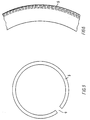
- Fig.5, is a top view of a spring ring,
- Fig.6, shows in a larger scale a section of the spring ring shown in Fig.5.
- Fig.7a,b,c and d, are vector diagrams for the acting axial forces's disintegration into composants by various deformations of the blocking arrangement.
- In Fig.1 and 2, a spear 1 is shown, which by a
screw thread 2 is screwed into aneck ring 3, welded on a container 4, of which only a fragment can be seen. Such a spear is normally used as a valve for dispensing beer, for example, under pressure of a drive gas, e.g. CO2 in a transportable container. This spear system itself serves in this connection only as an exemplification of the invention and is consequently not described in details here. - In the neck ring 3 a
groove 5 has been formed, in which a splitted spring ring 6 is placed, which in Fig.5 can be seen in a plane picture. In Fig.1 the spring ring is a conventional spring ring 7, and in Fig.2 aspring ring 8 according to the invention. In both cases the spring ring is shown in a relieved condition. - As shown in Fig.5 the spring ring 6 has an
open slit 9 permitting the spring ring to be squeezed together and into thegroove 5. This take place when the spear 1 is screwed into theneck ring 3 , and then a lowerconical face 10 on aninwards turning projection 11 of the spear 1 will press the spring ring into thegroove 5, and thus theprojection 11 will be able to pass down past the spring ring. As soon as this has taken place the spring ring will thereafter return to the relieved condition as shown i Fig.1 and 2, where the spring ring now reaches across an upwards turningface 12 on theprojection 11. - As it appears, the
inwards turning projection 11 will operate as a sort of a barb, which after being placed under the spring ring is unable to be displaced in the opposite direction. When the spear is to be dismounted it will therefore be necessary actively to force the spring ring into thegroove 5, so that theprojection 11 is allowed to pass up past the spring ring. For this purpose there is in the area around the spring ring formed a row ofpassage holes 13 along the periphery of the spear. When in normal use these holes are covered by ashield 14 made of a material, which relatively easily can be broken, for example plastic. In order to make it easier to break theshield 14 this is also provided with at least onebreakage indicator 15. - When the spear is to be dismounted, the
shield 14 is broken and removed, so that there will be free access to theholes 13 from the outside. With a special tool adapted to the purpose having pins, which can be let through theholes 13, the spring ring 6 then can be squeezed into thegroove 5, whereafter theprojection 11 can pass the spring ring and allow the dismounting of the spear. - A spear of the type shown in Fig.1 and 2 will normally always be fixed into the neck ring with a primary connection, which in itself with great security is able to absorb the forces by which the drive pressure in the container act on the spear in an outwards direction. In the cases shown, the spear 1 is assembled with the
neck ring 3 by means of athread 2, and without further preparations the spear can therefore be screwed off the neck ring. If this takes place while there still is an over-pressure in the container, the spear will suddenly with great force be shot out into the room. If the spear then hits a person near the container, for example the operator, he might be seriously injured or, at worse, be killed. - It is therefore necessary that the pressure in the container is relieved before the spear is being dismounted. Authorized operators are fully aware of this fact, while that will normally not be the case with unauthorized persons who, for some reason, might want to dismount the spear. The spring ring 7 and the upwards turning
face 12 of theprojection 11 and the upper, downwards turningface 16 of thegroove 5 will together form a blocking arrangement which precisely is meant to prevent unauthorized person from screwing off the spear. These persons will, due to theshield 14, not have a direct access to theholes 13, and therefore they will not be able to manipulate the spring ring 7 so that it is squeezed together in such a way that theprojection 11 can pass. In spite of this, it has been seen that unauthorized persons have been able to dismount the spear when using a conventional blocking arrangement, as shown in Fig.1. The reason for this is explained in the following, referring to the Fig. 3a,b and c, where the blocking arrangement, in larger scale as shown in Fig.1, can be seen in three different steps during the dismounting. - In Fig.3a, the spear 1 is unscrewed to such an extend in relation to the
neck ring 3, that anedge 17 of theprojection 11's upwards turningface 12 just has come to edgewise contact with the spring ring 7'slower side face 20, whereby the spring ring has been lifted up so anupper edge 18 of the spring ring has come to an edgewise contact with thegroove 5's downwards turningface 16. As shown, a inwardsturning cylinder face 22, placed over theprojection 11, is limiting the possibility of the spring ring to expand radially outwards, while the spring ring by squeezing freely is allowed to deform into thegroove 5 in the deformation direction, as shown by the arrow. - If the unscrewal is continued the spring ring will now be acted on by reverse axial forces, resulting in distorting of the spring ring, that means the cross-section of the spring ring is turning as compared to the starting point, as shown in Fig. 3b. As it can be seen, the axial forces are transmitted by edgewise contact between, on the one side the
edge 17 of theprojection 11's upwards turningface 12 and the spring ring 7's downwards turningface 20, and on the other side between theedge 19 of thegroove 5'supper side 16 and theupper side face 21 of the spring ring. In Fig. 3a,b and c the sizes of the angles, which the spring ring's side faces 20,21 are forming with a plane standing perpendicular to the central axis of the spear, have, for illustrative reasons, been drawn with some exaggeration. In practise, these angles will be so small that the arrangement will be self-blocking when in relieved position, that is, when the two parts only are attempted to be displaced axially in relation to each other. In this case the acting axial forces will not be able to squeeze the spring ring together in the deformation direction allowed. - This condition, however, will come to an end when the acting on the spring ring is changed from a resting load into a situation where the spring ring is rotating in relation to the
edges groove 5 or in the direction from the left to the right in Fig.7a, where both angles thus are positive. - The two side faces 20,21 are acted on by opposite directed equal axial forces F. The axial force F of the
side face 20 is in Fig.7a disintegrated in a normal force K1' and a horizontal composant K1". Correspondingly, the normal force F on theside face 21 is disintegrated in a normal force K2' and a horizontal composant K2". The total of the two horizontal composants K1", K2" are put together to the resultant R. In Fig.7a the resultant R is acting in the same direction as the deformation direction, and thus it will try to squeeze the spring ring radially into thegroove 5, whereby the spear could be dismounted in spite of the presence of the blocking arrangement. - The simultaneously acting friction forces will, however, as mentioned before, be able to prevent this from happening when the spring ring only is exposed to a resting load from the axial forces F. If the side faces 20,21 of the spring ring, however, simultaneously are acted on in the attack points at the
edges 17,19 (fig.3b) by a force standing perpendicular to the resultant R, the attack point inquestion - Such a second force, standing perpendicular to the resultant R, will precisely occur when the spear is rotated in relation to the corresponding neck ring. Thereby the spring ring is brought to rotate in relation to, at least, one of the attack points 17,19, which now, due to the above-mentioned conditions, will describe a spiral-like curve in relation to the surface of contact in question, as implied in fig.6. This spiral-like curve is, as regards the
attack point 17, running from the location along theside face 20, as shown in fig. 3b, to its end at the outer periphery of the spring ring. In this way the spring ring finally is worked or screwed totally free from theprojection 11, as shown i fig.3c. Hereafter the spear can now, without further ceremony, be demounted resulting in the previously mentioned risks. - As a spear thus being able to be dismounted, even if it should be secured against this by a blocking arrangement, is a result of the fact that, as it appears, the axial forces acting as reaction forces, when dismounting is attempted, have a positive resultant R, as shown in Fig.7a, when a conventional blocking arrangement is used.
- A conventional blocking arrangement will therefore only when being acted on by a resting load provide a satisfactory security against axial displacement between the two parts, while the arrangement, for the above-mentioned reasons, is liable to fail, when the two parts are moving simultaneously in another way in relation to each other, e.g. are carrying out a turning movement in relation to each other. The conventional blocking arrangements are therefore, in reality, of no use in securing for example a spear from being dismounted by an unauthorized person, if optimal security is demanded.
- This disadvantage of the conventional blocking systems is remedied by means of the embodiments shown as example in Fig.4a,4b and 4c regarding a blocking arrangement according to the invention. The matching vector diagrams are seen from Fig.7b,7c and 7d. Similar parts have in either case been given the same reference number as in Fig.3b,7a.
- Fig.4a,7b are almost identical to Fig.3b,7a with the significant difference that the upper side face 23 of the
groove 5 now forms an angle β, which is negative. As β at the same time is larger than α the resultant R will be negative, as shown in Fig.7b. In this case the resultant R is therefore pointing at the opposite direction of the deformation direction, and this causes the fact that the resultant R now instead, as in the conventional blocking arrangements trying to squeeze the spring ring together, will try to expand the latter radially outwards for abutting the inwards turningcylinder face 22 of the spear when this is turned in relation to the neck ring. The blocking arrangement according to the invention therefore provides complete security against an unauthorized person is dismounting the spear. - Fig. 4b shows another embodiment according to the invention. In this case the
groove 5 corresponds with the groove shown i fig. 3b. While the conventional spring ring 7 shown in fig. 3b has its greatest wall thickness at the inner diameter the spring ring according to the invention shown in fig. 4b is, however, thickest at the outer diameter. Thereby the side faces 24, 25 of thespring ring 8 will obtain the inclinations shown in fig. 7c, where theside face 25 inclines with a slightly positive angle of inclination α and theside face 24 with a larger negative angle of inclination β. In this way is obtained a larger negative resultant than in the case shown in fig. 4a, 7b and with that a proportionate larger security against unauthorized dismounting of the spear. - An additional security is obtained by the blocking arrangement shown in fig.4c,7d, combining the advantages of the blocking arrangements shown in fig.4a,4b. The
groove 5'supper side 23 has, as shown in fig.7d, the same negative angle of inclination as thecorresponding side 23 in fig.4a, and thespring ring 8 has a cross-section of precisely the same shape as in fig. 4b. As can be seen from fig.7d, an even larger resultant is obtained and thereby security against unauthorized dismounting of the spear as was the case before. - The embodiments shown for blocking arrangement according to the invention, are only to be understood as examples, and the effects mentioned according to the invention can obviously be combined in many ways in order to obtain exactly the rate of security which is demanded for a given construction.
- This construction might be a spear or any other construction, where two parts are to be mutually secured against axial displacement while they at the same time will be exposed to movement in relation to each other in other direction than the axial.
- These movements can, as described above, be a mutual turning between two parts, but also be two parts being rocked to and fro in relation to each other.
- The blocking arrangement, according to the invention, is also described above, and in the drawing shown as a blocking arrangement, which operates in the one axial direction. The blocking arrangement can, of course, be double-acting whereby each part has two opposite turning blocking faces.
- The deformation direction can moreover be opposite to the one shown in Fig.3a, the inside part having an outwards turning, cylindrical stop face for limiting the spring ring's radial deformation inwards, while the outside part is constructed in such a way that the spring ring is allowed to have a free radial expansion outwards in this.
Claims (5)
- A blocking arrangement for preventing that opposite acting axial forces axially can separate a substantially cylindrical first part (3) with a central axis and a mainly radially outwards extending first blocking face (16) in relation to an around the first part (3) concentrically placed second part (1) with an opposite to the first blocking face (16) turning, mainly radially inwards extending second blocking face (12), which have a larger inside diameter than the outside diameter of the first blocking face (16), whereby the arrangement is comprising; that between the two blocking faces (16;12) is placed a splitted spring ring (8), which in relieved position reaches across both blocking faces (16;12) and only in one radial direction is allowed a deformation being able to bring the spring ring (8) out of reach of the blocking face (16;12) placed in front as seen in relation to the deformation direction; that the spring ring (8) has a first side face (24) turning towards the first blocking face (16) and a second side face (25) turning towards the second blocking face (12); that the axial forces are transmitted from the first part (3) to the spring ring (8) and from this to the second part (1) by means of, mainly on both sides of the spring ring (8) operating edgewise contact with a working face (16;12;24,25), which in dependence of the construction chosen and the distortion of the spring ring under the subjected stress, can be either the blocking face (16;12) or the side face (24,25), both of which in relation to a plane standing perpendicular to the central axis, seen in axial section, forms an angle (α,β) which is equal to the attack angle (α,β) defined as the angle between the axial force acting on the respective face and the component of this force perpendicular to said face, characterized in, that the total of the size of the two attack angles (α,β), measured with positive sign, when the angle diverges in the deformation direction allowed, as maximum are equal to or less than zero.
- A blocking arrangement according to claim 1, characterized in that the spring ring (8) has greater thickness at the outside diameter than at the inside diameter.
- A blocking arrangement according to claim 1 or 2 or, characterized in that cross section of the spring ring (8) has the shape of a trapeze with inwards converging sides.
- A blocking arrangement according to one or more of the claims 1-3, where the spring ring (8) is placed in a groove (5) in one of the parts (3;1), and the allowed deformation direction of the spring ring (8) points towards the groove (5), one side of which also forms a blocking face (23), characterized in that this blocking face (23) in relation to one perpendicular to the central axis standing plane, seen in axial section, forms an angle (β), which converges into the deformation direction.
- A blocking arrangement according to one or more of the claims 1-4, characterized in that each part has opposite turning blocking faces (16;12).
Applications Claiming Priority (3)
| Application Number | Priority Date | Filing Date | Title |
|---|---|---|---|
| DK931375A DK137593D0 (en) | 1993-12-09 | 1993-12-09 | SAVING ARRANGEMENT |
| DK1375/93 | 1993-12-09 | ||
| PCT/DK1994/000463 WO1995016613A2 (en) | 1993-12-09 | 1994-12-09 | Blocking arrangement |
Publications (2)
| Publication Number | Publication Date |
|---|---|
| EP0683749A1 EP0683749A1 (en) | 1995-11-29 |
| EP0683749B1 true EP0683749B1 (en) | 1997-03-05 |
Family
ID=8104174
Family Applications (1)
| Application Number | Title | Priority Date | Filing Date |
|---|---|---|---|
| EP95903262A Expired - Lifetime EP0683749B1 (en) | 1993-12-09 | 1994-12-09 | Blocking arrangement |
Country Status (13)
| Country | Link |
|---|---|
| US (1) | US6047994A (en) |
| EP (1) | EP0683749B1 (en) |
| JP (1) | JP3713047B2 (en) |
| AT (1) | ATE149452T1 (en) |
| AU (1) | AU1219295A (en) |
| CA (1) | CA2153897A1 (en) |
| CZ (1) | CZ289640B6 (en) |
| DE (1) | DE69401917T2 (en) |
| DK (2) | DK137593D0 (en) |
| ES (1) | ES2098167T3 (en) |
| HU (1) | HU221074B1 (en) |
| PL (1) | PL179444B1 (en) |
| WO (1) | WO1995016613A2 (en) |
Families Citing this family (5)
| Publication number | Priority date | Publication date | Assignee | Title |
|---|---|---|---|---|
| NL1012660C2 (en) * | 1999-07-21 | 2001-01-23 | Dispense Systems Internat B V | Container for beer, soft drinks or wine has keg-valve with anti-tampering device has annual of seal divided and at least one location, and comprising once-only closure at location of division |
| NL1014951C1 (en) * | 1999-07-21 | 2001-01-23 | Dispense Systems Internat B V | Barrel with an annular seal. |
| GB201213626D0 (en) * | 2012-07-31 | 2012-09-12 | Eaton Aerospace Ltd | Valve for an aircraft |
| DE102015202161B4 (en) * | 2015-02-06 | 2016-11-03 | Zf Friedrichshafen Ag | joint assembly |
| GB2559394B (en) * | 2017-02-03 | 2020-04-15 | Petainer Large Container Ip Ltd | Closure with venting system |
Family Cites Families (17)
| Publication number | Priority date | Publication date | Assignee | Title |
|---|---|---|---|---|
| CA695250A (en) * | 1964-09-29 | B. Rondum Svend | Stab lock coupling for grooved pipe | |
| US2952480A (en) * | 1956-10-22 | 1960-09-13 | Beckman Instruments Inc | Fastening device detachably coupling grooved cylindrical surfaces |
| US3453005A (en) * | 1968-04-08 | 1969-07-01 | Scovill Manufacturing Co | Quick-connect safety coupling |
| US3718350A (en) * | 1971-09-27 | 1973-02-27 | Gen Motors Corp | Snap ring coupling |
| US3922011A (en) * | 1973-12-11 | 1975-11-25 | Tom Walters | Hose coupling |
| US4007953A (en) * | 1975-09-10 | 1977-02-15 | International Telephone And Telegraph Corporation | Removable captive coupling nut assembly |
| AU509587B2 (en) * | 1976-01-19 | 1980-05-15 | Sekisui Kagaku Kogyo Kabushiki Kaisha | Pipe joint endless locking ring and groove arrangement |
| US4229950A (en) * | 1979-03-02 | 1980-10-28 | Eastman Kodak Company | Coupling for end gudgeon and internally heated roller |
| US4240654A (en) * | 1979-09-28 | 1980-12-23 | International Harvester Company | Hose end coupling unit |
| EP0056295B1 (en) * | 1981-01-05 | 1984-10-31 | Alumasc Limited | Valved closure for kegs or casks |
| SE459279B (en) * | 1984-06-21 | 1989-06-19 | Volvo Ab | CLUTCH DEVICE ON PRESSURE MEDIUM CABLES |
| IT1191378B (en) * | 1985-03-29 | 1988-03-23 | Walterscheid Gmbh Jean | SNAP-IN DEVICE FOR THE CONNECTION OF THE POWER TAKE-OFF SHAFT OF A TRACTOR TO THE CARDAN SHAFT OPERATING AN OPERATING MACHINE |
| FR2614084B1 (en) * | 1987-04-17 | 1989-10-20 | Peugeot | DEVICE FOR QUICK CONNECTION OF A TIP TO A RECEIVING APPARATUS |
| JPH0317112Y2 (en) * | 1987-05-29 | 1991-04-11 | ||
| US4750765A (en) * | 1987-07-27 | 1988-06-14 | Stratoflex, Inc. | Quick-connect coupling |
| US5176413A (en) * | 1988-11-30 | 1993-01-05 | Stig Westman | Anchoring means for pipes with rhomboid-shaped grip ring |
| DK171720B1 (en) * | 1989-02-14 | 1997-04-07 | Micro Matic As | Valve Assembly device |
-
1993
- 1993-12-09 DK DK931375A patent/DK137593D0/en not_active Application Discontinuation
-
1994
- 1994-12-09 ES ES95903262T patent/ES2098167T3/en not_active Expired - Lifetime
- 1994-12-09 DE DE69401917T patent/DE69401917T2/en not_active Expired - Fee Related
- 1994-12-09 DK DK95903262.4T patent/DK0683749T3/en active
- 1994-12-09 WO PCT/DK1994/000463 patent/WO1995016613A2/en not_active Ceased
- 1994-12-09 PL PL94312379A patent/PL179444B1/en not_active IP Right Cessation
- 1994-12-09 EP EP95903262A patent/EP0683749B1/en not_active Expired - Lifetime
- 1994-12-09 HU HU9502297A patent/HU221074B1/en not_active IP Right Cessation
- 1994-12-09 AT AT95903262T patent/ATE149452T1/en not_active IP Right Cessation
- 1994-12-09 CA CA002153897A patent/CA2153897A1/en not_active Abandoned
- 1994-12-09 JP JP51647295A patent/JP3713047B2/en not_active Expired - Fee Related
- 1994-12-09 AU AU12192/95A patent/AU1219295A/en not_active Abandoned
- 1994-12-09 CZ CZ19951938A patent/CZ289640B6/en not_active IP Right Cessation
-
1995
- 1995-04-13 US US08/421,532 patent/US6047994A/en not_active Expired - Fee Related
Also Published As
| Publication number | Publication date |
|---|---|
| CA2153897A1 (en) | 1995-06-22 |
| HU9502297D0 (en) | 1995-10-30 |
| DE69401917D1 (en) | 1997-04-10 |
| HU221074B1 (en) | 2002-07-29 |
| JP3713047B2 (en) | 2005-11-02 |
| DK137593D0 (en) | 1993-12-09 |
| AU1219295A (en) | 1995-07-03 |
| WO1995016613A3 (en) | 1995-12-07 |
| ES2098167T3 (en) | 1997-04-16 |
| EP0683749A1 (en) | 1995-11-29 |
| HUT73480A (en) | 1996-08-28 |
| CZ193895A3 (en) | 1996-01-17 |
| DK0683749T3 (en) | 1997-09-01 |
| PL312379A1 (en) | 1996-04-15 |
| US6047994A (en) | 2000-04-11 |
| ATE149452T1 (en) | 1997-03-15 |
| DE69401917T2 (en) | 1997-07-03 |
| CZ289640B6 (en) | 2002-03-13 |
| WO1995016613A2 (en) | 1995-06-22 |
| JPH08506555A (en) | 1996-07-16 |
| PL179444B1 (en) | 2000-09-29 |
Similar Documents
| Publication | Publication Date | Title |
|---|---|---|
| US5228250A (en) | Tamper proof anchor bolt assembly | |
| US4484595A (en) | Tamper-proof cover for the operating nut of a fire hydrant | |
| EP0437019B1 (en) | Scored reverse buckling rupture disk assembly | |
| EP1454086B1 (en) | Pressure relief device assemblies | |
| US4944424A (en) | Safety cap assembly | |
| US6047994A (en) | Blocking arrangement | |
| US4838447A (en) | Pressure relief device with conical reverse buckling disc | |
| US5713496A (en) | Sealing for a container device | |
| US3121509A (en) | Damage resistant rupture disc assembly | |
| US4270730A (en) | Means to retain a valve stem | |
| EP0083473A1 (en) | Safety pressure relief device for pressure vessels | |
| US3435984A (en) | Safety vent structure | |
| DE69006006T2 (en) | Screw cap. | |
| WO1993006375A1 (en) | Tamper proof anchor bolt assembly | |
| GB2228055A (en) | A valve mounting assembly preventing unscrewing of the valve | |
| RU2569465C1 (en) | Safety membrane device | |
| WO1993019003A1 (en) | Safety keg assembly | |
| DE580546C (en) | Safety device for compressed air lines, especially for reversible internal combustion engines | |
| CN114109997A (en) | A nut anti-loose fitting and protective cap | |
| HK1001135B (en) | Lp gas container valve against disasters |
Legal Events
| Date | Code | Title | Description |
|---|---|---|---|
| PUAI | Public reference made under article 153(3) epc to a published international application that has entered the european phase |
Free format text: ORIGINAL CODE: 0009012 |
|
| 17P | Request for examination filed |
Effective date: 19950302 |
|
| AK | Designated contracting states |
Kind code of ref document: A1 Designated state(s): AT BE CH DE DK ES FR GB GR IE IT LI LU MC NL PT SE |
|
| 17Q | First examination report despatched |
Effective date: 19951124 |
|
| GRAG | Despatch of communication of intention to grant |
Free format text: ORIGINAL CODE: EPIDOS AGRA |
|
| GRAH | Despatch of communication of intention to grant a patent |
Free format text: ORIGINAL CODE: EPIDOS IGRA |
|
| GRAH | Despatch of communication of intention to grant a patent |
Free format text: ORIGINAL CODE: EPIDOS IGRA |
|
| GRAA | (expected) grant |
Free format text: ORIGINAL CODE: 0009210 |
|
| AK | Designated contracting states |
Kind code of ref document: B1 Designated state(s): AT BE CH DE DK ES FR GB GR IE IT LI LU MC NL PT SE |
|
| PG25 | Lapsed in a contracting state [announced via postgrant information from national office to epo] |
Ref country code: GR Free format text: LAPSE BECAUSE OF FAILURE TO SUBMIT A TRANSLATION OF THE DESCRIPTION OR TO PAY THE FEE WITHIN THE PRESCRIBED TIME-LIMIT Effective date: 19970305 |
|
| REF | Corresponds to: |
Ref document number: 149452 Country of ref document: AT Date of ref document: 19970315 Kind code of ref document: T |
|
| REG | Reference to a national code |
Ref country code: CH Ref legal event code: EP |
|
| REF | Corresponds to: |
Ref document number: 69401917 Country of ref document: DE Date of ref document: 19970410 |
|
| REG | Reference to a national code |
Ref country code: CH Ref legal event code: NV Representative=s name: PATENTANWALTSBUERO JEAN HUNZIKER |
|
| REG | Reference to a national code |
Ref country code: ES Ref legal event code: FG2A Ref document number: 2098167 Country of ref document: ES Kind code of ref document: T3 |
|
| ET | Fr: translation filed | ||
| ITF | It: translation for a ep patent filed | ||
| REG | Reference to a national code |
Ref country code: IE Ref legal event code: FG4D Free format text: 72430 |
|
| PG25 | Lapsed in a contracting state [announced via postgrant information from national office to epo] |
Ref country code: SE Effective date: 19970605 Ref country code: PT Effective date: 19970605 |
|
| REG | Reference to a national code |
Ref country code: DK Ref legal event code: T3 |
|
| PG25 | Lapsed in a contracting state [announced via postgrant information from national office to epo] |
Ref country code: LU Free format text: LAPSE BECAUSE OF NON-PAYMENT OF DUE FEES Effective date: 19971209 Ref country code: IE Free format text: LAPSE BECAUSE OF NON-PAYMENT OF DUE FEES Effective date: 19971209 |
|
| PLBE | No opposition filed within time limit |
Free format text: ORIGINAL CODE: 0009261 |
|
| STAA | Information on the status of an ep patent application or granted ep patent |
Free format text: STATUS: NO OPPOSITION FILED WITHIN TIME LIMIT |
|
| 26N | No opposition filed | ||
| PG25 | Lapsed in a contracting state [announced via postgrant information from national office to epo] |
Ref country code: MC Free format text: LAPSE BECAUSE OF NON-PAYMENT OF DUE FEES Effective date: 19980630 |
|
| REG | Reference to a national code |
Ref country code: GB Ref legal event code: IF02 |
|
| PG25 | Lapsed in a contracting state [announced via postgrant information from national office to epo] |
Ref country code: IT Free format text: LAPSE BECAUSE OF NON-PAYMENT OF DUE FEES;WARNING: LAPSES OF ITALIAN PATENTS WITH EFFECTIVE DATE BEFORE 2007 MAY HAVE OCCURRED AT ANY TIME BEFORE 2007. THE CORRECT EFFECTIVE DATE MAY BE DIFFERENT FROM THE ONE RECORDED. Effective date: 20051209 |
|
| PGFP | Annual fee paid to national office [announced via postgrant information from national office to epo] |
Ref country code: NL Payment date: 20071207 Year of fee payment: 14 Ref country code: DK Payment date: 20071205 Year of fee payment: 14 |
|
| PGFP | Annual fee paid to national office [announced via postgrant information from national office to epo] |
Ref country code: CH Payment date: 20071206 Year of fee payment: 14 Ref country code: AT Payment date: 20071210 Year of fee payment: 14 |
|
| PGFP | Annual fee paid to national office [announced via postgrant information from national office to epo] |
Ref country code: BE Payment date: 20071210 Year of fee payment: 14 |
|
| PGFP | Annual fee paid to national office [announced via postgrant information from national office to epo] |
Ref country code: GB Payment date: 20071207 Year of fee payment: 14 Ref country code: FR Payment date: 20071212 Year of fee payment: 14 Ref country code: ES Payment date: 20080118 Year of fee payment: 14 |
|
| PGFP | Annual fee paid to national office [announced via postgrant information from national office to epo] |
Ref country code: DE Payment date: 20071207 Year of fee payment: 14 |
|
| BERE | Be: lapsed |
Owner name: *MICRO MATIC A/S Effective date: 20081231 |
|
| REG | Reference to a national code |
Ref country code: CH Ref legal event code: PL |
|
| REG | Reference to a national code |
Ref country code: DK Ref legal event code: EBP |
|
| GBPC | Gb: european patent ceased through non-payment of renewal fee |
Effective date: 20081209 |
|
| PG25 | Lapsed in a contracting state [announced via postgrant information from national office to epo] |
Ref country code: AT Free format text: LAPSE BECAUSE OF NON-PAYMENT OF DUE FEES Effective date: 20081209 |
|
| NLV4 | Nl: lapsed or anulled due to non-payment of the annual fee |
Effective date: 20090701 |
|
| PG25 | Lapsed in a contracting state [announced via postgrant information from national office to epo] |
Ref country code: BE Free format text: LAPSE BECAUSE OF NON-PAYMENT OF DUE FEES Effective date: 20081231 |
|
| REG | Reference to a national code |
Ref country code: FR Ref legal event code: ST Effective date: 20090831 |
|
| PG25 | Lapsed in a contracting state [announced via postgrant information from national office to epo] |
Ref country code: LI Free format text: LAPSE BECAUSE OF NON-PAYMENT OF DUE FEES Effective date: 20081231 Ref country code: DE Free format text: LAPSE BECAUSE OF NON-PAYMENT OF DUE FEES Effective date: 20090701 Ref country code: CH Free format text: LAPSE BECAUSE OF NON-PAYMENT OF DUE FEES Effective date: 20081231 |
|
| PG25 | Lapsed in a contracting state [announced via postgrant information from national office to epo] |
Ref country code: NL Free format text: LAPSE BECAUSE OF NON-PAYMENT OF DUE FEES Effective date: 20090701 Ref country code: GB Free format text: LAPSE BECAUSE OF NON-PAYMENT OF DUE FEES Effective date: 20081209 |
|
| PG25 | Lapsed in a contracting state [announced via postgrant information from national office to epo] |
Ref country code: DK Free format text: LAPSE BECAUSE OF NON-PAYMENT OF DUE FEES Effective date: 20090105 |
|
| REG | Reference to a national code |
Ref country code: ES Ref legal event code: FD2A Effective date: 20081210 |
|
| PG25 | Lapsed in a contracting state [announced via postgrant information from national office to epo] |
Ref country code: FR Free format text: LAPSE BECAUSE OF NON-PAYMENT OF DUE FEES Effective date: 20081231 Ref country code: ES Free format text: LAPSE BECAUSE OF NON-PAYMENT OF DUE FEES Effective date: 20081210 |
|
| PGFP | Annual fee paid to national office [announced via postgrant information from national office to epo] |
Ref country code: IT Payment date: 20071210 Year of fee payment: 14 |
|
| PGRI | Patent reinstated in contracting state [announced from national office to epo] |
Ref country code: IT Effective date: 20091201 |
|
| PGRI | Patent reinstated in contracting state [announced from national office to epo] |
Ref country code: IT Effective date: 20091201 |