EP0683110A1 - Container-lid combination - Google Patents
Container-lid combination Download PDFInfo
- Publication number
- EP0683110A1 EP0683110A1 EP95303229A EP95303229A EP0683110A1 EP 0683110 A1 EP0683110 A1 EP 0683110A1 EP 95303229 A EP95303229 A EP 95303229A EP 95303229 A EP95303229 A EP 95303229A EP 0683110 A1 EP0683110 A1 EP 0683110A1
- Authority
- EP
- European Patent Office
- Prior art keywords
- lid
- side wall
- container body
- body according
- container
- Prior art date
- Legal status (The legal status is an assumption and is not a legal conclusion. Google has not performed a legal analysis and makes no representation as to the accuracy of the status listed.)
- Granted
Links
- 230000002093 peripheral effect Effects 0.000 claims abstract description 28
- 239000000463 material Substances 0.000 claims description 38
- 239000004033 plastic Substances 0.000 claims description 25
- 229920003023 plastic Polymers 0.000 claims description 25
- 239000002184 metal Substances 0.000 claims description 24
- 229910052751 metal Inorganic materials 0.000 claims description 24
- 239000000853 adhesive Substances 0.000 claims description 19
- 230000001070 adhesive effect Effects 0.000 claims description 19
- 239000004743 Polypropylene Substances 0.000 claims description 18
- -1 polypropylene Polymers 0.000 claims description 18
- 229920001155 polypropylene Polymers 0.000 claims description 18
- 230000004888 barrier function Effects 0.000 claims description 16
- 239000011324 bead Substances 0.000 claims description 13
- 239000004715 ethylene vinyl alcohol Substances 0.000 claims description 3
- 229920000219 Ethylene vinyl alcohol Polymers 0.000 claims description 2
- RZXDTJIXPSCHCI-UHFFFAOYSA-N hexa-1,5-diene-2,5-diol Chemical compound OC(=C)CCC(O)=C RZXDTJIXPSCHCI-UHFFFAOYSA-N 0.000 claims description 2
- 230000000063 preceeding effect Effects 0.000 claims 1
- 238000000034 method Methods 0.000 description 7
- 238000000576 coating method Methods 0.000 description 6
- 239000010410 layer Substances 0.000 description 6
- 229920000642 polymer Polymers 0.000 description 6
- 239000004922 lacquer Substances 0.000 description 4
- 238000007789 sealing Methods 0.000 description 4
- 239000004698 Polyethylene Substances 0.000 description 3
- 230000008901 benefit Effects 0.000 description 3
- 239000011248 coating agent Substances 0.000 description 3
- 229920001577 copolymer Polymers 0.000 description 3
- 238000005520 cutting process Methods 0.000 description 3
- 239000011888 foil Substances 0.000 description 3
- 229920000573 polyethylene Polymers 0.000 description 3
- 238000003466 welding Methods 0.000 description 3
- 206010000060 Abdominal distension Diseases 0.000 description 2
- VGGSQFUCUMXWEO-UHFFFAOYSA-N Ethene Chemical compound C=C VGGSQFUCUMXWEO-UHFFFAOYSA-N 0.000 description 2
- 239000005977 Ethylene Substances 0.000 description 2
- 239000005030 aluminium foil Substances 0.000 description 2
- 238000001816 cooling Methods 0.000 description 2
- 230000004927 fusion Effects 0.000 description 2
- 229920006395 saturated elastomer Polymers 0.000 description 2
- 239000002356 single layer Substances 0.000 description 2
- 238000003860 storage Methods 0.000 description 2
- 239000004593 Epoxy Substances 0.000 description 1
- LFQSCWFLJHTTHZ-UHFFFAOYSA-N Ethanol Chemical compound CCO LFQSCWFLJHTTHZ-UHFFFAOYSA-N 0.000 description 1
- 239000004677 Nylon Substances 0.000 description 1
- 239000002318 adhesion promoter Substances 0.000 description 1
- 239000012790 adhesive layer Substances 0.000 description 1
- 230000003466 anti-cipated effect Effects 0.000 description 1
- QVGXLLKOCUKJST-UHFFFAOYSA-N atomic oxygen Chemical compound [O] QVGXLLKOCUKJST-UHFFFAOYSA-N 0.000 description 1
- 238000005452 bending Methods 0.000 description 1
- 230000007797 corrosion Effects 0.000 description 1
- 238000005260 corrosion Methods 0.000 description 1
- 238000009826 distribution Methods 0.000 description 1
- 230000005489 elastic deformation Effects 0.000 description 1
- 239000012634 fragment Substances 0.000 description 1
- 238000010438 heat treatment Methods 0.000 description 1
- 230000006698 induction Effects 0.000 description 1
- JGEMYUOFGVHXKV-UPHRSURJSA-N malealdehyde Chemical compound O=C\C=C/C=O JGEMYUOFGVHXKV-UPHRSURJSA-N 0.000 description 1
- FPYJFEHAWHCUMM-UHFFFAOYSA-N maleic anhydride Chemical group O=C1OC(=O)C=C1 FPYJFEHAWHCUMM-UHFFFAOYSA-N 0.000 description 1
- 238000000465 moulding Methods 0.000 description 1
- 229920001778 nylon Polymers 0.000 description 1
- 229910052760 oxygen Inorganic materials 0.000 description 1
- 239000001301 oxygen Substances 0.000 description 1
- 239000011101 paper laminate Substances 0.000 description 1
- 239000002985 plastic film Substances 0.000 description 1
- 229920005606 polypropylene copolymer Polymers 0.000 description 1
- 239000000843 powder Substances 0.000 description 1
- 230000002035 prolonged effect Effects 0.000 description 1
- 230000000284 resting effect Effects 0.000 description 1
- 238000005096 rolling process Methods 0.000 description 1
- 238000004826 seaming Methods 0.000 description 1
- 239000002344 surface layer Substances 0.000 description 1
- 238000003856 thermoforming Methods 0.000 description 1
- 229920001169 thermoplastic Polymers 0.000 description 1
- 239000004416 thermosoftening plastic Substances 0.000 description 1
- 239000005028 tinplate Substances 0.000 description 1
- 125000000391 vinyl group Chemical group [H]C([*])=C([H])[H] 0.000 description 1
- 229920002554 vinyl polymer Polymers 0.000 description 1
Images


Classifications
-
- B—PERFORMING OPERATIONS; TRANSPORTING
- B65—CONVEYING; PACKING; STORING; HANDLING THIN OR FILAMENTARY MATERIAL
- B65D—CONTAINERS FOR STORAGE OR TRANSPORT OF ARTICLES OR MATERIALS, e.g. BAGS, BARRELS, BOTTLES, BOXES, CANS, CARTONS, CRATES, DRUMS, JARS, TANKS, HOPPERS, FORWARDING CONTAINERS; ACCESSORIES, CLOSURES, OR FITTINGS THEREFOR; PACKAGING ELEMENTS; PACKAGES
- B65D17/00—Rigid or semi-rigid containers specially constructed to be opened by cutting or piercing, or by tearing of frangible members or portions
- B65D17/50—Non-integral frangible members applied to, or inserted in, preformed openings, e.g. tearable strips or plastic plugs
- B65D17/501—Flexible tape or foil-like material
- B65D17/502—Flexible tape or foil-like material applied to the external part of the container wall only
-
- B—PERFORMING OPERATIONS; TRANSPORTING
- B65—CONVEYING; PACKING; STORING; HANDLING THIN OR FILAMENTARY MATERIAL
- B65D—CONTAINERS FOR STORAGE OR TRANSPORT OF ARTICLES OR MATERIALS, e.g. BAGS, BARRELS, BOTTLES, BOXES, CANS, CARTONS, CRATES, DRUMS, JARS, TANKS, HOPPERS, FORWARDING CONTAINERS; ACCESSORIES, CLOSURES, OR FITTINGS THEREFOR; PACKAGING ELEMENTS; PACKAGES
- B65D77/00—Packages formed by enclosing articles or materials in preformed containers, e.g. boxes, cartons, sacks or bags
- B65D77/10—Container closures formed after filling
- B65D77/20—Container closures formed after filling by applying separate lids or covers, i.e. flexible membrane or foil-like covers
- B65D77/2024—Container closures formed after filling by applying separate lids or covers, i.e. flexible membrane or foil-like covers the cover being welded or adhered to the container
-
- B—PERFORMING OPERATIONS; TRANSPORTING
- B65—CONVEYING; PACKING; STORING; HANDLING THIN OR FILAMENTARY MATERIAL
- B65D—CONTAINERS FOR STORAGE OR TRANSPORT OF ARTICLES OR MATERIALS, e.g. BAGS, BARRELS, BOTTLES, BOXES, CANS, CARTONS, CRATES, DRUMS, JARS, TANKS, HOPPERS, FORWARDING CONTAINERS; ACCESSORIES, CLOSURES, OR FITTINGS THEREFOR; PACKAGING ELEMENTS; PACKAGES
- B65D79/00—Kinds or details of packages, not otherwise provided for
- B65D79/005—Packages having deformable parts for indicating or neutralizing internal pressure-variations by other means than venting
- B65D79/0087—Packages having deformable parts for indicating or neutralizing internal pressure-variations by other means than venting the deformable part being located in a closure, e.g. in caps or lids
Definitions
- This invention relates to lids and containers having a side wall terminating in an annular portion defining the mouth of the container which is closed by a closure member the periphery of which is bonded to the annular portion.
- US Patent 5246134 (Polystar) describes a metal can body with a ring of plastics material fitted over an outward curl of the side wall of the can. A lid is peelably bonded to the plastics ring. An inner annulus of the plastics ring is flexible to bend as pressure develops during thermal processing of the contents of the lidded can. A disadvantage of this arrangement arises because the polymer used for the ring is expensive.
- This invention provides, in combination, a lid of polymeric material and a metal container body having side wall portion at one end of which an annular portion extends from the side wall to define a mouth of the container, said lid comprising a centre panel surrounded by a peripheral annular flange which extends outwardly and axially towards the side wall to define a seal with the annular portion of the side wall; characterised in that, the lid is made of an elastic barrier plastic material so that the lid may deform elastically during thermal processing and return to its original shape after thermal processing.
- the peripheral annular flange of the lid is inclined at an obtuse angle between 95° and 175° to an axis extending perpendicular to the central panel in order to co-operate with the annular portion of the side wall.
- the lid has a shape to permit a 10% increase in volume of the lidded container during thermal processing in order limit increase in pressure in the container to no more than 5 psi.
- the angle between the annular flange of the lid and an axis extending perpendicular to the central panel portion is in a range between 120° and 150°.
- annular portion of the side wall is an inwardly directed margin of side wall material.
- annular portion of the side wall is an inwardly directed margin of side wall material formed to terminate in an outwardly directed crushed curl.
- annular portion of the side wall is an upper surface of an annular bead formed in the side wall and the free edge of the side wall terminate in an outwardly directed curl.
- the annular portion of the side wall is on a metal ring attached to the side wall; or the annular portion of the side wall is a ring of plastics material clinched or adhered to the metal side wall portion.
- annular portion of the side wall is an outwardly directed flange supported by a neck of reduced diameter formed at the end of the side wall portion. If desired, the outwardly directed flange of the body may terminate in an inwardly directed curl.
- the seal between the peripheral flange of the lid and annular portion of the body is preferably a peelable seal.
- a pull-tab may extend laterally from the flange of the lid.
- the lid is preferably made from a laminate of several layers of plastics materials to achieve a desired barrier plastics material, however less stringent storage requirements may permit use of a single layer of plastics material, such as polypropylene or polyethylene, as lid material.
- a laminate of polypropylene/adhesive/ethylene-vinyl-alcohol/adhesive/polypropylene or the like may be used.
- the lid may have a flat central panel surrounded by a flexible channel portion which joins the centre panel to the peripheral flange of the lid.
- the centre panel of the lid may be, in cross-section, a segment of a circle spanning the peripheral flange of the lid so that expansion of volume is achieved as pressure in the container increases, as the contents are heated, to progressively evert the centre panel.
- the central panel may be made flexible by virtue of its thickness and material such as polymer sheet or by means of concentric flexible beads as is used in metal can ends or both.
- a benefit of using concentric beads is that volume expansions of the order of 10% of the container volume as filled are possible. This reduces the differential pressure in a saturated steam retort at 131°C from typically 30-40 psi down to 2-5 psi thus allowing a peelable seal to be used.
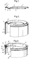
- Figure 1 shows a first embodiment of the lid 1 comprising a dished central panel 2 surrounded by a peripheral flange 3 which extends outwardly and downwardly to surround the centre panel.
- the peripheral flange is substantially frustoconical with an included angle of about 90° which gives an angle A to a central axis perpendicular to the central panel of about 45°.
- angles to this central axis may be between 5° and 85° preferably between 30° and 60°.
- the central panel comprises a flat centre panel 4 surrounded by an annular channel portion 5 the outer wall 6 of which joins the peripheral flange 3.
- Figure 2 shows the lid 1 fitted on the side wall 7 a can body.
- the side wall has an inturned rim 9 extending from the rest of the side wall at an obtuse angle B° of about 135° so that the flange 3 of the lid rests on the inturned flange 9 of the body to permit bonding together.
- the bond may be a permanent bond such as can be achieved by adhesive or fusion of polymer coatings on the lid and body or alternatively a peelable bond may be a achieved by use of appropriate coatings or surface layers of lid and body.
- the central portion 2 of the lid distends outwardly as the contents of the can expand, but by virtue of the angled flanges of lid and body, the bond is not put into a peel mode of loading so use of peel seals is possible.
- the lid 1 may be used to reclose the can 8.
- the can body 8 is preferably made from sheet metal provided with known surface coatings.
- the lid is preferably vacuum formed from a sheet of laminated barrier plastics material with or without a layer of aluminium foil.
- the flange of the lid is bonded by adhesive to the body flange 9.
- FIG 3 shows a second embodiment of the lid and container in which the lid 10 comprises a flat central panel 11 from the periphery of which depends a peripheral annular flange 12 which is inclined to an axis perpendicular to the flat central panel at an angle of about 30°.
- the lid 10 may be made of thin sheet metal or a laminate of barrier plastic materials, with or without an aluminium foil layer, flexible to distend elastically during thermal processing.
- a can body 13 made from sheet metal, has a substantially cylindrical side wall 14 comprising an annular inwardly directed bead 15 connecting the side wall 14 to a side wall margin 16 above the bead.
- the side wall margin terminates in an outwardly directed curl 17.
- the inwardly directed bead has three portions; an upwardly and radially inwardly inclined surface 18 extending from the side wall margin, an upright wall 19 extending from the inclined surface towards the interior of the container, and an annular portion 20 extending from the upright portion to the side wall.
- the inclined surface 18 makes an angle B° to the central axis of the can of 60° or an obtuse angle of 120° to the side wall 14 so that the flange of the lid and inclined surface are contiguous to provide a useful area for bonding.
- the side wall margin 16 serves to protect the bond from abuse.
- FIG. 4 shows a third embodiment of the lid and can body.
- the lid 21 is thermoformed from a sheet of barrier plastics to comprise a flat centre panel 22 a channel 23 the outer wall 24 of which connects with a peripheral flange 25 inclined to an axis perpendicular to the flat centre panel at an angle of about 45° surrounded by a stepped short portion 26 having a lateral lug 27.
- a benefit arising from use of the channel portion arises because the channel is able to flexibly bend to raise the centre panel so increasing the container volume by as much as 10% during thermally induced expansion of a product in the can so controlling the pressure differential in a saturated steam retort at 131°C from typically 30 to 40 psi to 2 to 5 psi so permitting a peelable seal to be used.
- the can body 28 has a side wall 29 terminating in a crushed curl 30 the upper surface of which gives a bond area inclined to the side wall at an angle to co-operate with the flange of the lid for bonding by a peelable seal.
- the crushed curl gives a stiff rim to define the mouth of the can.
- Figure 5 shows the can and lid of Figure 4 but with the lateral lug 27 a bent back on itself over the channel portion. This arrangement may be preferred if the lidded cans are placed on pallets and busse packed for distribution. Furthermore the bent back tab may be joined by a frangible weld to the inclined surface or top of the lid as a tamper-evident feature.
- FIG. 6 shows a fourth embodiment of the lid and can body in which the lid 31 has been thermoformed from a sheet of barrier plastics to comprise a flat centre panel 32, an annular wall 33 upstanding from the periphery of the centre panel, and an inclined peripheral flange 34 provided with a pull lug 35 bent over the centre panel to lie flat.
- the peripheral flange 34 is bonded to a ring of metal comprising an annular inclined surface 42 to which the peripheral flange is bonded, a chuck wall portion 38 upstanding from the lower edge of the inclined surface, and a seam portion 38 folded into the double seam 39 which connects the ring to a side wall 40 of a can body.
- the inclined surface 42 is in the form of a frustoconical annulus of metal the inner edge of which is curled back on itself so that the raw edge and upper part of the curl 42A are aligned with the lower outer portion 42 to present a smooth frustoconical surface to the flange of the lid. As shown in Figure 6 the curl is triangular in cross section.
- the flange of the lid covers the curl free edge so that bonding of the lid to the ring protects the free edge from corrosion by the product packed or the storage environment.
- the lid panel distends to accommodate increased pressure in a closed can by elastic deformation or bulging of the centre panel 32 and pulling in of material of the wall 33.
- the lid 31A is provided with an annular channel portion 41 which joins the flat centre panel 32 to the peripheral flange 34 which is inclined at about 120° to the side wall 40.
- the curl 42A is flattened to a fold.
- the double seam protects the peelable bond of lid and inclined flange surface, from abuse during transit and stacking.
- the ring may be made of thin metal so that it is inherently flexible to bend upwards to align with tensile forces arising in a distending lid so that peel forces do not develop at the bond between the lid and ring.
- flexibility of the metal ring is made less important by inclining the inclined surfaces 42, 42A of the ring and flange 34 of the lid at an angle expected to put the bond in shear during periods of maximum distention of the lid during thermal processing.
- Figures 8 and 9 show containers in which the lid is connected to the side wall of the container by a ring of thermoplastics material.
- the plastics ring 45 comprises an inclined annular portion 46, an annular rib 47 depending from the inclined portion, and a peripheral flange 48 engaged in the curl 49 of the side wall 50 of a can body. Entry of the peripheral flange into the body is limited by an inwardly directed bead 51 in the side wall 50 of the container body so that tight curling of the free edge of the side wall to the curl 49 compresses the peripheral flange 48 against the inwardly directed bead 51 to achieve an hermetic seal.
- the lid 52 of Figure 8 is similar to that used in the first and second embodiments except that the pull tab 53 is made separately from the lid and bonded or welded to the inclined surface 46 of the lid.
- This separately moulded pull tab can be made thicker than the lid so it is comfortable to grip but made of a cheaper mono-polymer, such as polyethylene, or polypropylene so that a large pull tab may be used without shred-scrap loss in the expensive barrier plastic sheet used for the lids.
- Figure 8A shows the pull tab bonded to the lid insitu on the plastics ring clinched to a can body. It will be noticed that the tab 53 is thicker than the lid material 52 and bonded to the inclined surface of the lid. A notch 54 in the pull tab enables the user to lift the tab before pulling so that the lid 52-to-ring bond at surface is subjected to a peel force during opening.
- Figure 9 shows a modified form of lid 55 comprising a flat centre panel 56, an outwardly convex expansion bead 57 surrounding the centre panel, an outwardly concave bead 58 surrounding the convex bead, and a peripheral flange 59 inclined at about 45° to an axis perpendicular to the flat centre panel.
- a plastics ring 60 comprises an inclined portion 61 extending at about 45° to a stepped cylindrical portion 62 which extends above and below the inclined portion.
- the lower portion 63 of the cylindrical portion is a plug fit in container body 64.
- the upper portion 65 of the cylindrical portion is of wider external diameter than the lower portion to limit entry into outwardly curled rim 66 of the body and arises to a height above the lid 55 and pull tab.
- the pull tab 67 extends laterally through a gap in the upper portion 65 so that like containers can be stacked with their weight resting on the upper portion and rim, no weight being put on the pull tab.
- the pull tab 67 may alternatively be made of a relatively thick moulding which is joined by welding to a lateral extension of the lid flange 59.
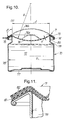
- Figure 10 shows a container body 70 drawn from sheet metal and closed by a dished lid 71 of polymeric material.
- the container is filled with a product 72 so that as the lidded container and product are heated during thermal processing the product expands to increase pressure in the container.
- the lid 71 of polymeric material starts to bulge in the middle and develops complete eversion (shown dashed) to increase the volume of the lidded container by about 10% so abating internal pressure and preventing development of a peel force on the seal between the annular flange 72 of the lid and annular portion of the body 74. Avoidance of peel forces on the seal permits use of a peelable seal 75 between the lid and annular portion so a consumer will find the container easy to open by peeling the lid from the can.
- the lids may be made from single layer of polymeric film or a multi-layer film may be used to achieve greater barriers to coater vapour and oxygen.
- the single film may be polypropylene, or polypropylene copolymer with, for example ethylene.
- the inter film adhesive layer of the lid is typically a maleic hydride modified polypropylene.
- the thickness of lid material may be between 200 and 600um but preferably in a range 300 to 400um.
- the lids of Figures 10 and 11 are made by thermoforming the chosen lid material.
- the lid is shown before excess pressure develops in the container.
- the lid comprises an outwardly concave centre panel 76 having a shape which is a segment of a cirle of radius R, and a peripheral flange depending from the panel at an obtuse angle A° to the vertical axis (a) perpendicular to the centre of the lid.
- the angle A° is between 95° and 175° preferably between 120° and 150°. In Figure 10 angle A° is about 120°.
- the container body of Figure 10 has a bottom wall 77 and a side wall 78 of diameter D upstanding from the periphery of the bottom wall.
- the side wall 78 is reduced in the diameter as its free end to make a shoulder 79, cylindrical diameter of neck 80 and outwardly directed annular portion which terminates in a peripheral inwardly directed curl which serves to stiffen the annular portion.
- the annular portion is inclined to the axis (a) at the same angle A° as the lid flange so that lid flange and body portion fit together to permit sealing.
- the interior surface of the container body may be coated with lacquer or other film.
- sealing of the body and lid is by means of an adhesive 75 which bonds the metal can body to the polymeric lid.
- the seal adhesive is comprised of polypropylene or polypropylene polymers chemically modified to increase the level of polar groups. Typically maleic carbonhydride is used to modify the polypropylene.
- the adhesive is preferably FDA approved.
- FIG 11 shows on enlarged scale a fragment of a preferred lid of barrier plastics material on an inclined annular portion of a can body generally as shown in Figure 10.
- the lid of barrier plastics mateiral is bonded by an adhesive 81 applied as a powder to a lacquer coating on the can interior and flange.
- a lid was applied to each can body and heat was applied by means of an induction coil which generated sufficient heat at the sealing surface interfaces to soften and melt the seal adhesive thereby enabling polar groups to function as adhesion promoters.
- Lacquer and adhesive materials are selected by lap and shear bond tests at 131°C using an Instrom Tensometer at a cross head space of 25mm/min. Bond strengths in excess of 300 N per 2.5mm strip were obtained for a 10mm overlapped joint in test specifications.
- Filled cans, lidded as described above, were thermally processed in a "Lagarde Retort Simulator" simulating a food processing cycle as occurs in a commercial apparatus such as the "HYDROSTAT” process. Conditions of process were:-
- This invention includes permanent bonds of the lid to the inclined body or ring surface such as can be achieved by fusing polymer surfaces of the lid and inclined surface.
- the invention also includes use of peelable bonds between the lid and inclined surface such as can be achieved by coating at least one of the lid or inclined surface with a peelable material such a copolymer.
- a lid material 71 comprising barrier layers and copolymer seal layer is a laminate of polypropylene/ adhesive/EVOH/adhesive/copolymer of polypropylene and polyethylene. Typically this laminate would be between 0.4 and 0.7mm thick with the ethylene vinyl alcohol (EVOH) constituting about 10% of thickness.
- the container bodies described are all made from sheet metal.
- the container may be made from a rectangular blank by rolling a blank to a cylinder, which is seamed by welding or fusion, and closed at one end by double seaming an ordinary can end. This built up technique is also used for rectangular or square tins.
- the container body may be made by deep drawing a blank of metal to make a seamless container. In both cases the inclined surface, and rim if present, may be formed by roll forming with or without die forming.
Landscapes
- Engineering & Computer Science (AREA)
- Mechanical Engineering (AREA)
- Closures For Containers (AREA)
- Rigid Containers With Two Or More Constituent Elements (AREA)
- Containers Opened By Tearing Frangible Portions (AREA)
Abstract
Description
- This invention relates to lids and containers having a side wall terminating in an annular portion defining the mouth of the container which is closed by a closure member the periphery of which is bonded to the annular portion.
- Our British Patent 1361415 describes cans in which a flat diaphragm is clinched between a curled rim and inward bead of the side wall. Opening was achieved by cutting the diaphragm.
- Our British Patent 2237259 describes and claims a metal container body having a side wall to which is attached a metal ring defining the mouth of the container. A closure member in the form of a flat disc of coated foil is bonded to flat abutting portions of the ring. The closure member is opened by cutting the foil or peeling the foil from the ring.
- Our British Patent 1601368 describes and claims a can body comprising a cylindrical side wall made by bending a rectangular metal blank to a cylinder, welding the adjacent edges and curling one end of the cylinder. A paper laminate diaphragm is adhered to the curled rim of semi-circular cross section. Both these later containers give a risk that a flat closure member will peel from the bond of the ring of the container if subjected to internal pressure.
- US Patent 5246134 (Polystar) describes a metal can body with a ring of plastics material fitted over an outward curl of the side wall of the can. A lid is peelably bonded to the plastics ring. An inner annulus of the plastics ring is flexible to bend as pressure develops during thermal processing of the contents of the lidded can. A disadvantage of this arrangement arises because the polymer used for the ring is expensive.
- This invention provides, in combination, a lid of polymeric material and a metal container body having side wall portion at one end of which an annular portion extends from the side wall to define a mouth of the container, said lid comprising a centre panel surrounded by a peripheral annular flange which extends outwardly and axially towards the side wall to define a seal with the annular portion of the side wall; characterised in that, the lid is made of an elastic barrier plastic material so that the lid may deform elastically during thermal processing and return to its original shape after thermal processing.
- The peripheral annular flange of the lid is inclined at an obtuse angle between 95° and 175° to an axis extending perpendicular to the central panel in order to co-operate with the annular portion of the side wall.
- And the lid has a shape to permit a 10% increase in volume of the lidded container during thermal processing in order limit increase in pressure in the container to no more than 5 psi.
- In preferred embodiments the angle between the annular flange of the lid and an axis extending perpendicular to the central panel portion is in a range between 120° and 150°.
- In a first embodiment the annular portion of the side wall is an inwardly directed margin of side wall material.
- In a second embodiment the annular portion of the side wall is an inwardly directed margin of side wall material formed to terminate in an outwardly directed crushed curl.
- In a further embodiment the annular portion of the side wall is an upper surface of an annular bead formed in the side wall and the free edge of the side wall terminate in an outwardly directed curl.
- In alternative embodiments, the annular portion of the side wall is on a metal ring attached to the side wall; or the annular portion of the side wall is a ring of plastics material clinched or adhered to the metal side wall portion.
- In a preferred embodiment the annular portion of the side wall is an outwardly directed flange supported by a neck of reduced diameter formed at the end of the side wall portion. If desired, the outwardly directed flange of the body may terminate in an inwardly directed curl.
- The seal between the peripheral flange of the lid and annular portion of the body is preferably a peelable seal. A pull-tab may extend laterally from the flange of the lid.
- The lid is preferably made from a laminate of several layers of plastics materials to achieve a desired barrier plastics material, however less stringent storage requirements may permit use of a single layer of plastics material, such as polypropylene or polyethylene, as lid material.
- When a barrier plastics material is required, a laminate of polypropylene/adhesive/ethylene-vinyl-alcohol/adhesive/polypropylene or the like may be used.
- In order to permit elastic expansion during thermal processing, the lid may have a flat central panel surrounded by a flexible channel portion which joins the centre panel to the peripheral flange of the lid. Alternatively, the centre panel of the lid may be, in cross-section, a segment of a circle spanning the peripheral flange of the lid so that expansion of volume is achieved as pressure in the container increases, as the contents are heated, to progressively evert the centre panel.
- The central panel may be made flexible by virtue of its thickness and material such as polymer sheet or by means of concentric flexible beads as is used in metal can ends or both. A benefit of using concentric beads is that volume expansions of the order of 10% of the container volume as filled are possible. This reduces the differential pressure in a saturated steam retort at 131°C from typically 30-40 psi down to 2-5 psi thus allowing a peelable seal to be used.
- Various embodiments will now be described by way of example and with reference to the acommpanying drawings in which:-
- Figure 1 is a side view a first embodiment of the lid cut-away on a diameter;
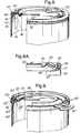
- Figure 2 is a perspective sketch of the lid of Figure 1 bonded to a container body;
- Figure 3 is a perspective sketch of a second embodiment of the lid when bonded to another can body;
- Figure 4 is a perspective sketch of a third embodiment of the lid when fitted on a curled rim of a container body;
- Figure 5 is a like view to Figure 4 but with the lid tab bent back on itself;
- Figure 6 is a perspective sketch of a fourth embodiment of the lid on a metal ring of the container body;
- Figure 7 is a fragmentary cross section of the ring and lid of Figure 6;
- Figure 8A is a perspective sketch of fifth embodiment of a lid on a ring of plastics material crimped to the can body;
- Figure 8 is an enlarged fragmentary section of the ring of Figure 8 at a pull tab;
- Figure 9 is a perspective view of a sixth embodiment in which the lid is bonded to a plug of plastics material which is bonded to the side wall of a can body.
- Figure 10 is a sectioned side view of a filled and lidded container; and
- Figure 11 is a fragmentary section of an alternative lidding material and body.
- Figure 1 shows a first embodiment of the
lid 1 comprising a dishedcentral panel 2 surrounded by a peripheral flange 3 which extends outwardly and downwardly to surround the centre panel. As shown in Figure 1 the peripheral flange is substantially frustoconical with an included angle of about 90° which gives an angle A to a central axis perpendicular to the central panel of about 45°. However angles to this central axis may be between 5° and 85° preferably between 30° and 60°. - The central panel comprises a flat centre panel 4 surrounded by an
annular channel portion 5 theouter wall 6 of which joins the peripheral flange 3. - Figure 2 shows the
lid 1 fitted on the side wall 7 a can body. The side wall has an inturned rim 9 extending from the rest of the side wall at an obtuse angle B° of about 135° so that the flange 3 of the lid rests on the inturned flange 9 of the body to permit bonding together. - The bond may be a permanent bond such as can be achieved by adhesive or fusion of polymer coatings on the lid and body or alternatively a peelable bond may be a achieved by use of appropriate coatings or surface layers of lid and body.
- During thermal processing of the contents of the lidded can body the
central portion 2 of the lid distends outwardly as the contents of the can expand, but by virtue of the angled flanges of lid and body, the bond is not put into a peel mode of loading so use of peel seals is possible. When a peelable seal is used thelid 1 may be used to reclose thecan 8. - In this first embodiment as shown in Figures 1 and 2 the
can body 8 is preferably made from sheet metal provided with known surface coatings. The lid is preferably vacuum formed from a sheet of laminated barrier plastics material with or without a layer of aluminium foil. The flange of the lid is bonded by adhesive to the body flange 9. - Figure 3 shows a second embodiment of the lid and container in which the
lid 10 comprises a flat central panel 11 from the periphery of which depends a peripheralannular flange 12 which is inclined to an axis perpendicular to the flat central panel at an angle of about 30°. - The
lid 10 may be made of thin sheet metal or a laminate of barrier plastic materials, with or without an aluminium foil layer, flexible to distend elastically during thermal processing. - In Figure 3 a
can body 13 made from sheet metal, has a substantiallycylindrical side wall 14 comprising an annular inwardly directedbead 15 connecting theside wall 14 to aside wall margin 16 above the bead. The side wall margin terminates in an outwardly directedcurl 17. As shown, the inwardly directed bead has three portions; an upwardly and radially inwardlyinclined surface 18 extending from the side wall margin, anupright wall 19 extending from the inclined surface towards the interior of the container, and anannular portion 20 extending from the upright portion to the side wall. Theinclined surface 18 makes an angle B° to the central axis of the can of 60° or an obtuse angle of 120° to theside wall 14 so that the flange of the lid and inclined surface are contiguous to provide a useful area for bonding. Theside wall margin 16 serves to protect the bond from abuse. When the lids shown in Figures 2 and 3 are permanently bonded to the inclined surface of their can bodies the opening is achieved by cutting the lid with a knife. When a peelable seal is used the lids may be peeled from the inclined surfaces to that the lids may be used to reclose their can bodies. - Figure 4 shows a third embodiment of the lid and can body. The
lid 21 is thermoformed from a sheet of barrier plastics to comprise a flat centre panel 22 achannel 23 theouter wall 24 of which connects with aperipheral flange 25 inclined to an axis perpendicular to the flat centre panel at an angle of about 45° surrounded by a steppedshort portion 26 having alateral lug 27. A benefit arising from use of the channel portion arises because the channel is able to flexibly bend to raise the centre panel so increasing the container volume by as much as 10% during thermally induced expansion of a product in the can so controlling the pressure differential in a saturated steam retort at 131°C from typically 30 to 40 psi to 2 to 5 psi so permitting a peelable seal to be used. - In Figure 4 the
can body 28 has aside wall 29 terminating in a crushedcurl 30 the upper surface of which gives a bond area inclined to the side wall at an angle to co-operate with the flange of the lid for bonding by a peelable seal. The crushed curl gives a stiff rim to define the mouth of the can. - During thermal processing expansion of the contents of the
can body 28 is accommodated by distention of theflat panel 22 andchannel 23 so that little or no peel force is put on the peelable seal. If the panel deformation becomes the sufficient to pull the channel to a convex continuum the load on the inclined bonded surfaces is in shear, not peel. - Figure 5 shows the can and lid of Figure 4 but with the lateral lug 27 a bent back on itself over the channel portion. This arrangement may be preferred if the lidded cans are placed on pallets and busse packed for distribution. Furthermore the bent back tab may be joined by a frangible weld to the inclined surface or top of the lid as a tamper-evident feature.
- Figure 6 shows a fourth embodiment of the lid and can body in which the
lid 31 has been thermoformed from a sheet of barrier plastics to comprise aflat centre panel 32, anannular wall 33 upstanding from the periphery of the centre panel, and an inclinedperipheral flange 34 provided with apull lug 35 bent over the centre panel to lie flat. - The
peripheral flange 34 is bonded to a ring of metal comprising an annularinclined surface 42 to which the peripheral flange is bonded, achuck wall portion 38 upstanding from the lower edge of the inclined surface, and aseam portion 38 folded into thedouble seam 39 which connects the ring to a side wall 40 of a can body. Theinclined surface 42 is in the form of a frustoconical annulus of metal the inner edge of which is curled back on itself so that the raw edge and upper part of thecurl 42A are aligned with the lowerouter portion 42 to present a smooth frustoconical surface to the flange of the lid. As shown in Figure 6 the curl is triangular in cross section. - As shown in Figures 6 and 7 the flange of the lid covers the curl free edge so that bonding of the lid to the ring protects the free edge from corrosion by the product packed or the storage environment. In Figure 6 the lid panel distends to accommodate increased pressure in a closed can by elastic deformation or bulging of the
centre panel 32 and pulling in of material of thewall 33. - In Figure 7 the
lid 31A is provided with anannular channel portion 41 which joins theflat centre panel 32 to theperipheral flange 34 which is inclined at about 120° to the side wall 40. As shown in Figure 7 thecurl 42A is flattened to a fold. - One advantage of using this
metal ring 36 that the double seam protects the peelable bond of lid and inclined flange surface, from abuse during transit and stacking. If desired the ring may be made of thin metal so that it is inherently flexible to bend upwards to align with tensile forces arising in a distending lid so that peel forces do not develop at the bond between the lid and ring. However, flexibility of the metal ring is made less important by inclining theinclined surfaces flange 34 of the lid at an angle expected to put the bond in shear during periods of maximum distention of the lid during thermal processing. - Figures 8 and 9 show containers in which the lid is connected to the side wall of the container by a ring of thermoplastics material.
- In Figure 8 the
plastics ring 45 comprises an inclinedannular portion 46, anannular rib 47 depending from the inclined portion, and aperipheral flange 48 engaged in thecurl 49 of theside wall 50 of a can body. Entry of the peripheral flange into the body is limited by an inwardly directedbead 51 in theside wall 50 of the container body so that tight curling of the free edge of the side wall to thecurl 49 compresses theperipheral flange 48 against the inwardly directedbead 51 to achieve an hermetic seal. - The
lid 52 of Figure 8 is similar to that used in the first and second embodiments except that thepull tab 53 is made separately from the lid and bonded or welded to theinclined surface 46 of the lid. This separately moulded pull tab can be made thicker than the lid so it is comfortable to grip but made of a cheaper mono-polymer, such as polyethylene, or polypropylene so that a large pull tab may be used without shred-scrap loss in the expensive barrier plastic sheet used for the lids. - Figure 8A shows the pull tab bonded to the lid insitu on the plastics ring clinched to a can body. It will be noticed that the
tab 53 is thicker than thelid material 52 and bonded to the inclined surface of the lid. Anotch 54 in the pull tab enables the user to lift the tab before pulling so that the lid 52-to-ring bond at surface is subjected to a peel force during opening. - Figure 9 shows a modified form of lid 55 comprising a
flat centre panel 56, an outwardlyconvex expansion bead 57 surrounding the centre panel, an outwardlyconcave bead 58 surrounding the convex bead, and aperipheral flange 59 inclined at about 45° to an axis perpendicular to the flat centre panel. - A
plastics ring 60 comprises an inclined portion 61 extending at about 45° to a steppedcylindrical portion 62 which extends above and below the inclined portion. Thelower portion 63 of the cylindrical portion is a plug fit incontainer body 64. Theupper portion 65 of the cylindrical portion is of wider external diameter than the lower portion to limit entry into outwardly curledrim 66 of the body and arises to a height above the lid 55 and pull tab. - The
pull tab 67 extends laterally through a gap in theupper portion 65 so that like containers can be stacked with their weight resting on the upper portion and rim, no weight being put on the pull tab. - The
pull tab 67 may alternatively be made of a relatively thick moulding which is joined by welding to a lateral extension of thelid flange 59. - Figure 10 shows a
container body 70 drawn from sheet metal and closed by a dishedlid 71 of polymeric material. As shown in Figure 10, the container is filled with aproduct 72 so that as the lidded container and product are heated during thermal processing the product expands to increase pressure in the container. Under the influence of heat and increased pressure thelid 71 of polymeric material starts to bulge in the middle and develops complete eversion (shown dashed) to increase the volume of the lidded container by about 10% so abating internal pressure and preventing development of a peel force on the seal between theannular flange 72 of the lid and annular portion of thebody 74. Avoidance of peel forces on the seal permits use of apeelable seal 75 between the lid and annular portion so a consumer will find the container easy to open by peeling the lid from the can. - The lids may be made from single layer of polymeric film or a multi-layer film may be used to achieve greater barriers to coater vapour and oxygen. For example the single film may be polypropylene, or polypropylene copolymer with, for example ethylene. A barrier plastic material 87 in the form of extruded sheet and comprise polypropylene/adhesive/ethylene/vinyl/alcohol (EVOH)/adhesive/polypropylene (as shown in Figure 11) or polypropylene/nylon/laminates. The inter film adhesive layer of the lid is typically a maleic hydride modified polypropylene. The thickness of lid material may be between 200 and 600um but preferably in a range 300 to 400um. The lids of Figures 10 and 11 are made by thermoforming the chosen lid material.
- In Figure 10 the lid is shown before excess pressure develops in the container. The lid comprises an outwardly
concave centre panel 76 having a shape which is a segment of a cirle of radius R, and a peripheral flange depending from the panel at an obtuse angle A° to the vertical axis (a) perpendicular to the centre of the lid. The angle A° is between 95° and 175° preferably between 120° and 150°. In Figure 10 angle A° is about 120°. - The container body of Figure 10 has a
bottom wall 77 and aside wall 78 of diameter D upstanding from the periphery of the bottom wall. Theside wall 78 is reduced in the diameter as its free end to make ashoulder 79, cylindrical diameter ofneck 80 and outwardly directed annular portion which terminates in a peripheral inwardly directed curl which serves to stiffen the annular portion. The annular portion is inclined to the axis (a) at the same angle A° as the lid flange so that lid flange and body portion fit together to permit sealing. The interior surface of the container body may be coated with lacquer or other film. - In Figure 10 sealing of the body and lid is by means of an adhesive 75 which bonds the metal can body to the polymeric lid. The seal adhesive is comprised of polypropylene or polypropylene polymers chemically modified to increase the level of polar groups. Typically maleic carbonhydride is used to modify the polypropylene. The adhesive is preferably FDA approved.
- Figure 11 shows on enlarged scale a fragment of a preferred lid of barrier plastics material on an inclined annular portion of a can body generally as shown in Figure 10. In this example the lid of barrier plastics mateiral is bonded by an adhesive 81 applied as a powder to a lacquer coating on the can interior and flange. In this example details are tabulated:-
Lid material = polypropylene/adhesive/EVOH/ = adhesive/polypropylene Lid thickness t = 400um Lid: panel concave radius R = 62.1mm Lid and flange angle A° = 120° Lid panel/neck diameter "d" = 72mm Lidded volume change when concave lid everted = 36.9mls Seal adhesive = Maleic anhydride modified polypropylene Container body = tinplate Container coating "L" = epoxy based lacquer - A lid was applied to each can body and heat was applied by means of an induction coil which generated sufficient heat at the sealing surface interfaces to soften and melt the seal adhesive thereby enabling polar groups to function as adhesion promoters.
- Lacquer and adhesive materials are selected by lap and shear bond tests at 131°C using an Instrom Tensometer at a cross head space of 25mm/min. Bond strengths in excess of 300 N per 2.5mm strip were obtained for a 10mm overlapped joint in test specifications.
- Filled cans, lidded as described above, were thermally processed in a "Lagarde Retort Simulator" simulating a food processing cycle as occurs in a commercial apparatus such as the "HYDROSTAT" process. Conditions of process were:-
- Come-up Time
- = 15 mins
- Process Time
- = 75 mins
- Process Temp
- = 121° and 131°C
- Pressure during process
- = 1.2 bar
- Cooling Time
- = 30 mins
- During this prolonged period of heating and cooling it was observed that the original concave shape of the lid everted from its concave arcuate cross section to bulge as a convex form 76a, 76b in which the peripheral surface of the centre panel is substantially aligned with the peripheral flange sealing bond and container body flange so that during high pressure arising during processing the bond is on shear mode of loading, not a peel mode.
- If higher process pressures are anticipated, and greater container volume compensation is desired, it may be necessary to increase the angle A° of annular portion, bond, and lid flange to, for example 95°.
- This invention includes permanent bonds of the lid to the inclined body or ring surface such as can be achieved by fusing polymer surfaces of the lid and inclined surface. The invention also includes use of peelable bonds between the lid and inclined surface such as can be achieved by coating at least one of the lid or inclined surface with a peelable material such a copolymer. One example of a
lid material 71 comprising barrier layers and copolymer seal layer is a laminate of polypropylene/ adhesive/EVOH/adhesive/copolymer of polypropylene and polyethylene. Typically this laminate would be between 0.4 and 0.7mm thick with the ethylene vinyl alcohol (EVOH) constituting about 10% of thickness. - The container bodies described are all made from sheet metal. The container may be made from a rectangular blank by rolling a blank to a cylinder, which is seamed by welding or fusion, and closed at one end by double seaming an ordinary can end. This built up technique is also used for rectangular or square tins. Alternatively the container body may be made by deep drawing a blank of metal to make a seamless container. In both cases the inclined surface, and rim if present, may be formed by roll forming with or without die forming.
Claims (16)
- In combination, a lid of polymeric material and a metal container body having a side wall portion at one end of which an annular portion extends from the side wall to define a mouth of the container,
said lid comprising a centre panel surrounded by a peripheral annular flange which extends outwardly and axially towards the side wall to define a seal with an annular portion of the side wall;
characterised in that:
the lid is made of an elastic barrier plastic material so that the lid may deform elastically during thermal processing and return to its original shape after thermal processing;
the peripheral annular flange of the lid is inclined to an obtuse angle between 95° and 175° to an axis extending perpendicular to the central panel in order to co-operate with the annular portion of the side wall;
and the lid has a shape to permit a 10% increase in volume of the lidded container during thermal processing in order limit increase in pressure in the container to no more than 5 psi. - A lid and container body according to claim 1 wherein the angle between the annular flange of the lid and an axis extending perpendicular to the central panel portion is in a range between 120° and 150°.
- A lid and container body according to claim 1 or claim 2 wherein the annular portion of the side wall is an inwardly directed margin of side wall material.
- A lid and container body according to claim 1 or claim 2 wherein the annular portion of the side wall is an inwardly directed margin of side wall material formed to terminate in an outwardly directed crushed curl.
- A lid and container body according to claim 1 or claim 2 wherein the annular portion of the side wall is an upper surface of an annular bead formed in the side wall and the free edge of the side wall terminates in an outwardly directed curl.
- A lid and container body according to claim 1 or claim 2 wherein the annular portion of the side wall is on a metal ring attached to the side wall.
- A lid and container body according to claim 1 or claim 2 wherein the annular portion of the side wall is a ring of plastics material clinched or adhered to the metal side wall portion.
- A lid and container body according to claim 1 or claim 2 wherein the annular portion of the side wall is an outwardly flange supported by a neck of reduced diameter formed at the end of the side wall portion.
- A lid and container body according to claim 8 wherein the outwardly directed flange of the body terminates in an inwardly directed curl.
- A lid and container body according to any preceeding claim wherein the seal between the peripheral flange of the lid and annular portion of the body is a peelable seal.
- A lid and container body according to any preceding claim wherein the pull-tab extends laterally from the flange of the lid.
- A lid and container body according to any preceding claim wherein the lid is made from a laminate of several layers of plastics materials to achieve a desired barrier palstics material.
- A lid and container body according to claim 12 wherein the barrier plastics material is a laminate of polypropylene/adhesive/ethylene-vinyl-alcohol/adhesive/polypropylne.
- A lid and container body according to claim 1 wherein the lid has a flat central panel surrounded by a channel portion which joins the centre panel to the peripheral flange of the lid.
- A lid and container body according to claim 1 wherein the centre panel of the lid is, in cross-section, a segment of a circle spanning the peripheral flange of the lid.
- A lid and container substantially as in hereinbefore described with reference to Figures 1 and 2, Figures 3, Figures 4 and 5, Figures 6 and 7, Figure 8, Figure 9 or Figure 10 and 11, of the accompanying drawings.
Applications Claiming Priority (2)
| Application Number | Priority Date | Filing Date | Title |
|---|---|---|---|
| GB9410228A GB2289663A (en) | 1994-05-21 | 1994-05-21 | Containers and lids bonded thereto |
| GB9410228 | 1994-05-21 |
Publications (2)
| Publication Number | Publication Date |
|---|---|
| EP0683110A1 true EP0683110A1 (en) | 1995-11-22 |
| EP0683110B1 EP0683110B1 (en) | 1998-09-16 |
Family
ID=10755521
Family Applications (1)
| Application Number | Title | Priority Date | Filing Date |
|---|---|---|---|
| EP95303229A Expired - Lifetime EP0683110B1 (en) | 1994-05-21 | 1995-05-12 | Container-lid combination |
Country Status (4)
| Country | Link |
|---|---|
| US (1) | US5725120A (en) |
| EP (1) | EP0683110B1 (en) |
| DE (1) | DE69504749T2 (en) |
| GB (1) | GB2289663A (en) |
Cited By (12)
| Publication number | Priority date | Publication date | Assignee | Title |
|---|---|---|---|---|
| EP0802124A1 (en) * | 1996-04-19 | 1997-10-22 | BENOIST GIRARD & Cie | Air-impermeable container with peelable cover |
| EP0943553A4 (en) * | 1997-07-11 | 2000-07-26 | A K Tech Lab Inc | Hermetic seal and wide-mouthed bottle sealed by the seal |
| EP1193179A4 (en) * | 2000-04-06 | 2004-12-08 | Ishida Seisakusho | Packaging container, packaging body including the same, and packaging method |
| EP1658226A2 (en) | 2003-08-19 | 2006-05-24 | Impress Group B.V. | Lever ring having a slanted flat strip |
| WO2006092364A3 (en) * | 2005-03-01 | 2006-11-30 | Crown Packaging Technology Inc | Packaging can and method and apparatus for its manufacture |
| WO2007077533A2 (en) | 2006-01-05 | 2007-07-12 | Bausch & Lomb Incorporated | Tool and method for heat sealing lidstocks tp plastic containers |
| KR100984710B1 (en) * | 2003-07-01 | 2010-10-01 | 크라운 팩키징 테크놀러지, 인코포레이티드 | How to adjust the pressure inside the can |
| EP2248731A1 (en) | 2009-05-07 | 2010-11-10 | Crown Packaging Technology, Inc | Container with clamped seal |
| WO2012072383A1 (en) | 2010-11-29 | 2012-06-07 | Crown Packaging Technology, Inc. | Closure |
| US8746489B2 (en) | 2008-06-03 | 2014-06-10 | Valspar Sourcing, Inc. | Easy-open container and container coating |
| EP2497718B1 (en) * | 2006-02-03 | 2015-06-10 | Ardagh MP West France S.A. | Process for producing a lid closure for a food can |
| US11142379B2 (en) | 2014-07-16 | 2021-10-12 | Koninklijke Douwe Egberts B.V. | Die-cut lid and associated container and method |
Families Citing this family (40)
| Publication number | Priority date | Publication date | Assignee | Title |
|---|---|---|---|---|
| DE29609130U1 (en) * | 1996-05-21 | 1997-09-18 | Rasselstein Hoesch GmbH, 56564 Neuwied | Easy to open can lid |
| DE29804789U1 (en) * | 1998-03-17 | 1998-05-14 | Technotron GmbH, 67550 Worms | Multi-part resealable plastic packaging |
| US20030062370A1 (en) * | 1999-02-10 | 2003-04-03 | Ball Melville Douglas | Can with peelably bonded closure |
| US6547093B1 (en) * | 2000-02-28 | 2003-04-15 | General Mills, Inc. | Plastic container for food products |
| US6427862B1 (en) * | 2000-11-07 | 2002-08-06 | Ming-Tang Hsu | Self-opening can |
| WO2002057154A1 (en) * | 2001-01-16 | 2002-07-25 | Ajava Pinata, Llc | Suspended containers |
| ES2256159T3 (en) * | 2001-12-20 | 2006-07-16 | Impress Group B.V. | COVER WITH HERMETIC CLOSURE SHEET THAT UNDERSTANDS A TONGUE TONGUE. |
| US7086545B2 (en) | 2002-01-16 | 2006-08-08 | Ajava Pinata, L.L.C. | Suspended containers |
| AU2003234509A1 (en) * | 2002-05-06 | 2003-11-17 | Ajava Pinata, Llc | Suspended containers |
| KR200289188Y1 (en) | 2002-06-11 | 2002-09-13 | 전정욱 | Readily openable can lid |
| US7296700B2 (en) * | 2002-07-11 | 2007-11-20 | Remington Health Products, L.L.C. | Method and apparatus for metering liquid nutritional supplements |
| US8074817B1 (en) | 2002-07-11 | 2011-12-13 | Remington Health Products, L.L.C. | Method and apparatus for metering liquid nutritional supplements |
| MXPA05000686A (en) * | 2002-07-19 | 2005-04-08 | Avery Dennison Corp | Labeling method employing two-part curable adhesives. |
| US7137524B2 (en) * | 2003-07-25 | 2006-11-21 | Sonoco Development, Inc. | Easy-opening container and plastic closure thereof for hermetic sealing |
| US20050145630A1 (en) * | 2004-01-05 | 2005-07-07 | Sonoco Development, Inc. | Easily openable closure for a retortable container having a metal end to which a membrane is sealed |
| AU2005206169A1 (en) * | 2004-01-16 | 2005-08-04 | William M. Heyn | Angled sealing surface for container end panel |
| US7378625B2 (en) * | 2004-03-09 | 2008-05-27 | Ball Corporation | Microwavable metallic container |
| US8080770B2 (en) * | 2004-03-09 | 2011-12-20 | Ball Corporation | Microwavable metallic container |
| US7112771B2 (en) * | 2004-03-09 | 2006-09-26 | Ball Corporation | Microwavable metallic container |
| US20050252918A1 (en) * | 2004-05-11 | 2005-11-17 | Sonoco Development, Inc. | Container having a metal end to which a membrane is sealed |
| USD510024S1 (en) | 2004-07-01 | 2005-09-27 | Ball Corporation | Metallic microwavable container |
| US20060191940A1 (en) * | 2005-02-25 | 2006-08-31 | Heyn William M | Sealing surfaces for container end panels |
| US8528770B2 (en) | 2005-09-15 | 2013-09-10 | Wells Enterprises, Inc. | Self-venting food container |
| US20070075083A1 (en) * | 2005-10-04 | 2007-04-05 | Mc Clellan W T | Non-contaminating milk or food container seal and seal removal system |
| US20110233211A1 (en) * | 2005-10-04 | 2011-09-29 | Mc Clellan W Thomas | One-piece non-contaminating milk or food container seal and seal removal system |
| US20070272693A1 (en) * | 2006-05-26 | 2007-11-29 | Sonoco Development, Inc. | Membrane Lid with Recessed Tab, and Container Incorporating Same |
| US8191726B2 (en) * | 2006-07-20 | 2012-06-05 | Crown Packaging Technology, Inc. | Can end having curved end panel surfaces |
| DE202006017508U1 (en) * | 2006-11-15 | 2007-02-08 | Rembe Gmbh | Blast pressure discharge mechanism for use in container, has modular rack, which holds wall, where bars are arranged between base and cover units of rack and are inserted and detachably fixed in retainer openings |
| US8020550B2 (en) * | 2007-01-25 | 2011-09-20 | Repetti Iii Daniel J | Intervening heat conducting medium |
| ATE464234T1 (en) * | 2007-02-28 | 2010-04-15 | Impress Group Bv | VESSEL WITH EASY-OPEN FLAP, EASY-OPEN FLAP AND FLAP THEREFOR |
| US20130161324A1 (en) * | 2009-05-05 | 2013-06-27 | James R. Gilliam, Jr. | Non-detachable beverage closure with a peel open cover system |
| US8714402B2 (en) | 2010-01-21 | 2014-05-06 | General Mills, Inc. | Thermoformed container assembly for food products |
| US20110226771A1 (en) * | 2010-03-17 | 2011-09-22 | Silgan Containers Llc | Container assembly with strainer |
| HUE038025T2 (en) * | 2011-07-21 | 2018-09-28 | Crown Packaging Technology Inc | Metal cans with peelable lids |
| WO2014066810A1 (en) * | 2012-10-26 | 2014-05-01 | Berry Plastics Corporation | Closure for container |
| US9828134B2 (en) * | 2013-10-21 | 2017-11-28 | Ziegler Robert A | Canister with dispersing aperture |
| WO2016176672A1 (en) | 2015-04-30 | 2016-11-03 | Berry Plastics Corporation | Container closure |
| US10435204B2 (en) | 2017-08-04 | 2019-10-08 | Anchor Packaging, Llc | Tamper evident food container with accordiated pull tab |
| BR112020007255B1 (en) * | 2017-12-07 | 2023-04-25 | Nippon Steel Corporation | HOT SEALED LID AND CAN |
| BR112022008169A2 (en) * | 2019-11-08 | 2022-09-20 | Ball Corp | REVELABLE CAN END WITH PERMANENT FLIP |
Citations (8)
| Publication number | Priority date | Publication date | Assignee | Title |
|---|---|---|---|---|
| US1627042A (en) * | 1925-05-06 | 1927-05-03 | Thomas S Mason | Container |
| DE2609525A1 (en) * | 1976-03-08 | 1977-09-15 | Pfeiffer Ohler Eisen Theob | Hot-filled material container - has membrane compensating for internal pressure alterations while cooling down |
| CH655072A5 (en) * | 1983-04-05 | 1986-03-27 | Holdt J W Von | Container |
| EP0357276A1 (en) * | 1988-09-02 | 1990-03-07 | General Foods Corporation | Vacuum packed canned product and method using foil membrane end closure |
| EP0357123A2 (en) * | 1988-08-15 | 1990-03-07 | Shell Internationale Researchmaatschappij B.V. | Thermoplastic lid for thermoplastic container |
| EP0408268A2 (en) * | 1989-07-10 | 1991-01-16 | CarnaudMetalbox plc | Method and apparatus for manufacturing a ring for a container closure |
| WO1991007325A1 (en) * | 1989-11-22 | 1991-05-30 | Yhtyneet Paperitehtaat Oy | Container and a lid for closing the same |
| WO1993012978A1 (en) * | 1991-12-23 | 1993-07-08 | Polystar Packaging, Inc. | Press-on closure with peelable end panel |
Family Cites Families (5)
| Publication number | Priority date | Publication date | Assignee | Title |
|---|---|---|---|---|
| US3208627A (en) * | 1963-04-15 | 1965-09-28 | Nat Can Corp | Reclosable can |
| US4583656A (en) * | 1985-06-17 | 1986-04-22 | Vercon, Inc. | Container with improved sealing lip |
| JPH02180148A (en) * | 1988-12-27 | 1990-07-13 | Keiji Yanai | Vessel lid with safe opening edge and manufacturing method thereof |
| DE3925068A1 (en) * | 1989-07-28 | 1991-02-07 | Schmalbach Lubeca | TWO OR THREE PIECE CONTAINERS, IN PART. MADE OF SHEET METAL |
| US5353943A (en) * | 1993-03-15 | 1994-10-11 | Sonoco Products Company | Easy-opening composite closure for hermetic sealing of a packaging container by double seaming |
-
1994
- 1994-05-21 GB GB9410228A patent/GB2289663A/en not_active Withdrawn
-
1995
- 1995-05-12 DE DE69504749T patent/DE69504749T2/en not_active Expired - Lifetime
- 1995-05-12 EP EP95303229A patent/EP0683110B1/en not_active Expired - Lifetime
- 1995-05-16 US US08/442,113 patent/US5725120A/en not_active Expired - Lifetime
Patent Citations (10)
| Publication number | Priority date | Publication date | Assignee | Title |
|---|---|---|---|---|
| US1627042A (en) * | 1925-05-06 | 1927-05-03 | Thomas S Mason | Container |
| DE2609525A1 (en) * | 1976-03-08 | 1977-09-15 | Pfeiffer Ohler Eisen Theob | Hot-filled material container - has membrane compensating for internal pressure alterations while cooling down |
| CH655072A5 (en) * | 1983-04-05 | 1986-03-27 | Holdt J W Von | Container |
| EP0357123A2 (en) * | 1988-08-15 | 1990-03-07 | Shell Internationale Researchmaatschappij B.V. | Thermoplastic lid for thermoplastic container |
| EP0357276A1 (en) * | 1988-09-02 | 1990-03-07 | General Foods Corporation | Vacuum packed canned product and method using foil membrane end closure |
| EP0408268A2 (en) * | 1989-07-10 | 1991-01-16 | CarnaudMetalbox plc | Method and apparatus for manufacturing a ring for a container closure |
| GB2237259A (en) * | 1989-07-10 | 1991-05-01 | Metal Box Plc | Container closure |
| WO1991007325A1 (en) * | 1989-11-22 | 1991-05-30 | Yhtyneet Paperitehtaat Oy | Container and a lid for closing the same |
| WO1993012978A1 (en) * | 1991-12-23 | 1993-07-08 | Polystar Packaging, Inc. | Press-on closure with peelable end panel |
| US5246134A (en) * | 1991-12-23 | 1993-09-21 | Polystar Packaging, Inc. | Press-on closure with peelable end panel |
Cited By (19)
| Publication number | Priority date | Publication date | Assignee | Title |
|---|---|---|---|---|
| EP0802124A1 (en) * | 1996-04-19 | 1997-10-22 | BENOIST GIRARD & Cie | Air-impermeable container with peelable cover |
| EP0943553A4 (en) * | 1997-07-11 | 2000-07-26 | A K Tech Lab Inc | Hermetic seal and wide-mouthed bottle sealed by the seal |
| EP1193179A4 (en) * | 2000-04-06 | 2004-12-08 | Ishida Seisakusho | Packaging container, packaging body including the same, and packaging method |
| KR100984710B1 (en) * | 2003-07-01 | 2010-10-01 | 크라운 팩키징 테크놀러지, 인코포레이티드 | How to adjust the pressure inside the can |
| US8240501B2 (en) | 2003-07-01 | 2012-08-14 | Crown Packaging Technology, Inc. | Method of controlling in-can pressure during thermal processing |
| EP2332849A1 (en) | 2003-08-19 | 2011-06-15 | Impress Metal Packaging S.A. | Cover ring having a slanted part and manufacturing process |
| EP1658226A2 (en) | 2003-08-19 | 2006-05-24 | Impress Group B.V. | Lever ring having a slanted flat strip |
| US9895737B2 (en) | 2005-03-01 | 2018-02-20 | Crown Packaging Technology, Inc. | Packaging can and method and apparatus for its manufacture |
| US8746488B2 (en) | 2005-03-01 | 2014-06-10 | Crown Packaging Technology, Inc. | Packaging can and method and apparatus for its manufacture |
| WO2006092364A3 (en) * | 2005-03-01 | 2006-11-30 | Crown Packaging Technology Inc | Packaging can and method and apparatus for its manufacture |
| WO2007077533A3 (en) * | 2006-01-05 | 2007-12-06 | Bausch & Lomb | Tool and method for heat sealing lidstocks tp plastic containers |
| WO2007077533A2 (en) | 2006-01-05 | 2007-07-12 | Bausch & Lomb Incorporated | Tool and method for heat sealing lidstocks tp plastic containers |
| EP2497718B1 (en) * | 2006-02-03 | 2015-06-10 | Ardagh MP West France S.A. | Process for producing a lid closure for a food can |
| US8746489B2 (en) | 2008-06-03 | 2014-06-10 | Valspar Sourcing, Inc. | Easy-open container and container coating |
| EP2248731A1 (en) | 2009-05-07 | 2010-11-10 | Crown Packaging Technology, Inc | Container with clamped seal |
| WO2012072383A1 (en) | 2010-11-29 | 2012-06-07 | Crown Packaging Technology, Inc. | Closure |
| US9475620B2 (en) | 2010-11-29 | 2016-10-25 | Crown Packaging Technology, Inc. | Closure |
| US11142379B2 (en) | 2014-07-16 | 2021-10-12 | Koninklijke Douwe Egberts B.V. | Die-cut lid and associated container and method |
| US11325760B2 (en) | 2014-07-16 | 2022-05-10 | Koninklijke Douwe Egberts B.V. | Die-cut lid and associated container and method |
Also Published As
| Publication number | Publication date |
|---|---|
| GB9410228D0 (en) | 1994-07-06 |
| DE69504749T2 (en) | 1999-05-06 |
| GB2289663A (en) | 1995-11-29 |
| US5725120A (en) | 1998-03-10 |
| EP0683110B1 (en) | 1998-09-16 |
| DE69504749D1 (en) | 1998-10-22 |
Similar Documents
| Publication | Publication Date | Title |
|---|---|---|
| EP0683110B1 (en) | Container-lid combination | |
| AP168A (en) | Supporting ring for container closure. | |
| US12397963B2 (en) | Container assembly having a heat-sealed metal end, a metal end therefor, and a method for making same | |
| US4466553A (en) | Composite container construction | |
| AU573842B2 (en) | Containers | |
| US5131556A (en) | Easy-open lid | |
| US20090032535A1 (en) | Container | |
| AU709340B2 (en) | Container and closure with in-turned seam | |
| AU682532B2 (en) | Package with pouring device for fluid substances, process for manufacturing package for fluid substances and tool for carrying out the process | |
| EP0132468B1 (en) | Container body | |
| US20130105499A1 (en) | Three-Piece Can and Method of Making Same | |
| EP0050667A1 (en) | Composite container construction | |
| EP4054946B1 (en) | Metal container and metal closure thereof | |
| EP1800770A1 (en) | Can body with a sealing compound placed on a step or flange and method of forming such a can body |
Legal Events
| Date | Code | Title | Description |
|---|---|---|---|
| PUAI | Public reference made under article 153(3) epc to a published international application that has entered the european phase |
Free format text: ORIGINAL CODE: 0009012 |
|
| AK | Designated contracting states |
Kind code of ref document: A1 Designated state(s): DE FR GB |
|
| 17P | Request for examination filed |
Effective date: 19960508 |
|
| 17Q | First examination report despatched |
Effective date: 19961205 |
|
| GRAG | Despatch of communication of intention to grant |
Free format text: ORIGINAL CODE: EPIDOS AGRA |
|
| GRAG | Despatch of communication of intention to grant |
Free format text: ORIGINAL CODE: EPIDOS AGRA |
|
| GRAH | Despatch of communication of intention to grant a patent |
Free format text: ORIGINAL CODE: EPIDOS IGRA |
|
| GRAH | Despatch of communication of intention to grant a patent |
Free format text: ORIGINAL CODE: EPIDOS IGRA |
|
| GRAA | (expected) grant |
Free format text: ORIGINAL CODE: 0009210 |
|
| AK | Designated contracting states |
Kind code of ref document: B1 Designated state(s): DE FR GB |
|
| REF | Corresponds to: |
Ref document number: 69504749 Country of ref document: DE Date of ref document: 19981022 |
|
| ET | Fr: translation filed | ||
| PLBE | No opposition filed within time limit |
Free format text: ORIGINAL CODE: 0009261 |
|
| STAA | Information on the status of an ep patent application or granted ep patent |
Free format text: STATUS: NO OPPOSITION FILED WITHIN TIME LIMIT |
|
| 26N | No opposition filed | ||
| REG | Reference to a national code |
Ref country code: GB Ref legal event code: IF02 |
|
| REG | Reference to a national code |
Ref country code: DE Ref legal event code: R082 Ref document number: 69504749 Country of ref document: DE Representative=s name: CALLIES, RAINER, DIPL.-PHYS. DR.RER.NAT., DE Ref country code: DE Ref legal event code: R082 Ref document number: 69504749 Country of ref document: DE Representative=s name: RAINER CALLIES, DE |
|
| PGFP | Annual fee paid to national office [announced via postgrant information from national office to epo] |
Ref country code: GB Payment date: 20140521 Year of fee payment: 20 |
|
| PGFP | Annual fee paid to national office [announced via postgrant information from national office to epo] |
Ref country code: FR Payment date: 20140527 Year of fee payment: 20 Ref country code: DE Payment date: 20140521 Year of fee payment: 20 |
|
| REG | Reference to a national code |
Ref country code: DE Ref legal event code: R071 Ref document number: 69504749 Country of ref document: DE |
|
| REG | Reference to a national code |
Ref country code: GB Ref legal event code: PE20 Expiry date: 20150511 |
|
| PG25 | Lapsed in a contracting state [announced via postgrant information from national office to epo] |
Ref country code: GB Free format text: LAPSE BECAUSE OF EXPIRATION OF PROTECTION Effective date: 20150511 |