EP0683097B1 - Dispositif de liaison - Google Patents
Dispositif de liaison Download PDFInfo
- Publication number
- EP0683097B1 EP0683097B1 EP95303198A EP95303198A EP0683097B1 EP 0683097 B1 EP0683097 B1 EP 0683097B1 EP 95303198 A EP95303198 A EP 95303198A EP 95303198 A EP95303198 A EP 95303198A EP 0683097 B1 EP0683097 B1 EP 0683097B1
- Authority
- EP
- European Patent Office
- Prior art keywords
- piston means
- inlet
- link apparatus
- body element
- piston
- Prior art date
- Legal status (The legal status is an assumption and is not a legal conclusion. Google has not performed a legal analysis and makes no representation as to the accuracy of the status listed.)
- Expired - Lifetime
Links
- 239000012530 fluid Substances 0.000 claims description 21
- 238000006073 displacement reaction Methods 0.000 claims description 5
- 238000007789 sealing Methods 0.000 claims description 3
- 238000000926 separation method Methods 0.000 claims description 3
- 239000003999 initiator Substances 0.000 description 1
- 238000000034 method Methods 0.000 description 1
- 230000035939 shock Effects 0.000 description 1
- 230000011664 signaling Effects 0.000 description 1
Images
Classifications
-
- B—PERFORMING OPERATIONS; TRANSPORTING
- B64—AIRCRAFT; AVIATION; COSMONAUTICS
- B64D—EQUIPMENT FOR FITTING IN OR TO AIRCRAFT; FLIGHT SUITS; PARACHUTES; ARRANGEMENT OR MOUNTING OF POWER PLANTS OR PROPULSION TRANSMISSIONS IN AIRCRAFT
- B64D25/00—Emergency apparatus or devices, not otherwise provided for
- B64D25/08—Ejecting or escaping means
- B64D25/10—Ejector seats
-
- Y—GENERAL TAGGING OF NEW TECHNOLOGICAL DEVELOPMENTS; GENERAL TAGGING OF CROSS-SECTIONAL TECHNOLOGIES SPANNING OVER SEVERAL SECTIONS OF THE IPC; TECHNICAL SUBJECTS COVERED BY FORMER USPC CROSS-REFERENCE ART COLLECTIONS [XRACs] AND DIGESTS
- Y10—TECHNICAL SUBJECTS COVERED BY FORMER USPC
- Y10T—TECHNICAL SUBJECTS COVERED BY FORMER US CLASSIFICATION
- Y10T137/00—Fluid handling
- Y10T137/1624—Destructible or deformable element controlled
- Y10T137/1632—Destructible element
- Y10T137/1669—Tensile or sheer pin or bolt
-
- Y—GENERAL TAGGING OF NEW TECHNOLOGICAL DEVELOPMENTS; GENERAL TAGGING OF CROSS-SECTIONAL TECHNOLOGIES SPANNING OVER SEVERAL SECTIONS OF THE IPC; TECHNICAL SUBJECTS COVERED BY FORMER USPC CROSS-REFERENCE ART COLLECTIONS [XRACs] AND DIGESTS
- Y10—TECHNICAL SUBJECTS COVERED BY FORMER USPC
- Y10T—TECHNICAL SUBJECTS COVERED BY FORMER US CLASSIFICATION
- Y10T137/00—Fluid handling
- Y10T137/8593—Systems
- Y10T137/86493—Multi-way valve unit
- Y10T137/86574—Supply and exhaust
- Y10T137/8667—Reciprocating valve
- Y10T137/86678—Combined disk or plug and gate or piston
Definitions
- This invention relates to a link apparatus capable of accommodating relative extension and/or retraction, and defining a fluid passage.
- extension or retraction of the apparatus may displace fluid into or out of the apparatus with a possible increase or decrease in fluid pressure.
- This can cause difficulties as the variation in pressure and/or fluid displacement may have undesirable effects elsewhere in the system.
- the link is in a fluid logic circuit
- the variation in fluid pressure due to extension or retraction may be misinterpreted as a pressure signalling pulse.
- a particular application of interest to the applicants is the telescopic "trombone" unit which extends between an ejector seat and the airframe in a military aircraft. This unit is required to transmit a signal in the form of a pressure pulse or a shock wave from the seat to a canopy jettison unit during an emergency ejection procedure. In normal operation the unit must accommodate limited extension and retraction movement due to relative movement, e.g. due to differential thermal expansion etc, but this must not produce anything that might be seen as a pressure pulse, otherwise there could be disastrous consequences.
- US-A-3 466 062 discloses a telescopic tube arrangement which comprises a first component including two concentric tubes fixed with respect to each other, and a third concentric tube having at one end an annular piston which is slidably received in the annular gap between the first mentioned two tubes.
- the annular piston sealingly engages both the inner surface of the outer tube and the outer surface of the inner tube.
- the third concentric tube also is in sliding and sealing engagement with the inner surface of the free end of the outer of the two concentric tubes.
- annular piston and dimensions of the tubes are carefully selected such that on displacement of the third tube relative to the other two, any change in volume between the volume defined between the third concentric tube and the inner concentric tube is matched by an equal and opposite change in the volume between the third concentric tube and the outer concentric tube.
- this invention provides a fluid link apparatus capable of extension and/or retraction, said apparatus comprising:-
- the piston element preferably includes a generally longitudinal bore extending from its distal end and terminated by at least one generally transverse bore opening into a region of said body element between said two seal regions.
- the piston means conveniently includes a collar element arranged to cooperate with said seal regions to limit routine extension and/or retraction movement of the piston means, and the collar element may be releasably attached to said piston means by a frangible connection to allow removal thereof and to allow separation of said piston element and said body element.
- the piston means is advantageously movable into a position in which the portion of the passage leading from the piston inlet/outlet port is blocked, but the portion of the passage leading from the body inlet/outlet port is vented to the exterior of the body element.
- the piston means and said body element may each include attachment means for attachment to a respective structural component, for example an ejector seat and the airframe in an aircraft, respectively.
- said inlet/outlet ports extend generally perpendicularly, whilst in another said inlet/outlet ports are generally in-line.
- link unit illustrated there are intended to extend between the ejector seat and the airframe in a military aircraft.
- a pressure signal is generated on board the seat which needs to be transmitted to a canopy jettison initiator unit.
- the link unit is also required to accommodate relative movement during the initial moments of ejection.
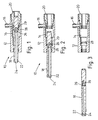
- the first embodiment of link unit 10 comprises a generally cylindrical body 12 with a stepped internal bore 14 and a transverse outlet port 16 communicating with the bore.
- a piston 18 Through one end of the body 12 (the left hand end as viewed) projects one end of a piston 18, and the other end of the body 12 is closed by a hollow cylindrical plug 20 which slidably and sealably receives the other end of the piston 18.
- the free end of the piston is pivotally secured to the ejection seat, and the body 12 is secured to the airframe or a part associated therewith.
- the piston 18 is of uniform outer diameter apart from the left hand end which terminates in an inlet port 22.
- the inlet port 22 continues as a longitudinal passage 24 extending about two thirds along the length of the piston 18.
- a collar 28 is secured to the piston 18 by a shear rivet 29.
- the inlet and outlet ports 22, 16 are in communication and the link unit may extend to accommodate movement. Because the other end of the piston 18 is received in the plug 20, when the unit 10 begins to extend, there is no net displacement of the volume of fluid within the unit, at least until the end leaves the plug 20. Thus, up to that stage, extension and retraction may occur without displacing fluid from the link and without causing an increase or a decrease in the pressure to either side of the unit. Conversely, the fluid pressure acting between the inlet and the outlet does not generate any significant extension or retraction force or significantly affect extension or retraction movement, and so 100% pressure balance may be achieved.
- a pressure pulse generated by a pyrotechnic unit on board the seat is transmitted by the link unit 10 to initiate canopy jettison.
- the ejection seat begins to move relative to the aircraft structure and so the piston 18 extends relative to the body 12 until the collar 28 engages the shoulder of the stepped bore of the body, as seen in Figure 2.
- the second embodiment is an in-line unit but has generally similar features to the first embodiment.
- the body 32 is stepped as before but instead of being transverse, the outlet port 36 is in-line and forms part of the plug 40 which closes the body 32.
- the plug 40 has a central stem defining an inner bore 41 which receives the other end of the piston 38 which is similar in all respects to the piston 18 of the first embodiment, including the collar 48.
- the inner bore 41 connects via vent passage 43 to atmosphere. Operation of this second embodiment is essentially similar to that of the first embodiment.
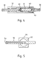
- FIG. 5 this illustrates diagrammatically the principle of operation of the first two embodiments.
- the piston 50 is slidably mounted in the body 52 and there is a fluid passage connecting the inlet port 54 on the piston and the outlet port 56 on the body.
- the piston can slide relative to the body without displacing fluid to or from the unit. In effect movement of an increment of the length of the piston out of the chamber is compensated by equal movement into the chamber.
Landscapes
- Business, Economics & Management (AREA)
- Emergency Management (AREA)
- Engineering & Computer Science (AREA)
- Aviation & Aerospace Engineering (AREA)
- Actuator (AREA)
- Fluid-Pressure Circuits (AREA)
- Joints Allowing Movement (AREA)
Claims (9)
- Dispositif formant connecteur hydraulique (10) pouvant s'étendre et/ou se rétracter, ledit dispositif comportant :caractérisé en ce que lesdits moyens formant piston allongé (18) ont de manière générale une dimension extérieure uniforme, et ledit élément formant corps (12) comporte deux zones étanches fixées relativement espacées dans une disposition d'étanchéité avec lesdits moyens formant piston allongé (18) au niveau d'emplacements espacés longitudinalement, et définissant un volume confiné qui communique avec lesdits moyens d'entrée/sortie de fluide (16).un élément formant corps (12) ayant un orifice d'entrée/sortie de fluide (16),des moyens formant piston allongé (18) ayant un orifice d'entrée/sortie de fluide (22), et étant montés de manière coulissante à l'intérieur dudit élément formant corps (12) pour se déplacer par rapport à celui-ci le long d'un axe d'extension/de retrait,ledit élément formant corps (12) et lesdits moyens formant piston (18) étant agencés pour fournir un passage d'écoulement entre lesdits orifices d'entrée/sortie (16, 22) dans lequel le déplacement net de fluide pendant une extension ou un retrait dans des limites préétablies est nul ou relativement faible,
- Dispositif formant connecteur selon la revendication 1, dans lequel lesdits moyens formant piston (18) comportent un alésage de manière générale longitudinal (24) s'étendant à partir de son extrémité distale, et qui se termine par au moins un alésage de manière générale transversal (26) s'ouvrant dans une zone dudit élément formant corps située entre lesdites deux zones étanches.
- Dispositif formant connecteur selon la revendication 1 ou 2, dans lequel lesdits moyens formant piston (18) comportent un élément formant collier (28) agencé pour coopérer avec lesdites zones étanches afin de limiter un déplacement permanent d'extension et/ou de retrait des moyens formant piston (18).
- Dispositif formant connecteur selon la revendication 3, dans lequel ledit élément formant collier (28) est fixé de manière libérable auxdits moyens formant piston par l'intermédiaire d'une connexion cassante pour permettre un enlèvement de celui-ci, et pour permettre une séparation desdits moyens formant piston (18) et dudit élément formant corps (12).
- Dispositif formant connecteur selon l'une quelconque des revendications précédentes, dans lequel lesdits moyens formant piston (18) sont mobiles dans une position dans laquelle la partie (26) du passage (24, 26) partant de l'orifice d'entrée/sortie de piston (22) est bloquée, mais la partie du passage partant de l'orifice d'entrée/sortie de corps (16) est mise à l'air libre à l'extérieur de l'élément formant corps (12).
- Dispositif formant connecteur selon l'une quelconque des revendications précédentes, dans lequel lesdits moyens formant piston (18) et ledit élément formant corps (12) comportent chacun des moyens de fixation pour être fixés sur un composant structurel respectif.
- Dispositif formant connecteur selon la revendication 6, dans lequel lesdits composants structurels comportent un siège éjecteur et la structure d'un avion.
- Dispositif formant connecteur selon l'une quelconque des revendications précédentes, dans lequel lesdits orifices d'entrée/sortie (16, 22) s'étendent de manière générale perpendiculairement.
- Dispositif formant connecteur selon l'une quelconque des revendications précédentes, dans lequel lesdits orifices d'entrée/sortie (36) sont de manière générale alignés.
Applications Claiming Priority (2)
| Application Number | Priority Date | Filing Date | Title |
|---|---|---|---|
| GB9409720 | 1994-05-14 | ||
| GB9409720A GB9409720D0 (en) | 1994-05-14 | 1994-05-14 | Link apparatus |
Publications (3)
| Publication Number | Publication Date |
|---|---|
| EP0683097A2 EP0683097A2 (fr) | 1995-11-22 |
| EP0683097A3 EP0683097A3 (fr) | 1997-09-24 |
| EP0683097B1 true EP0683097B1 (fr) | 2001-06-27 |
Family
ID=10755178
Family Applications (1)
| Application Number | Title | Priority Date | Filing Date |
|---|---|---|---|
| EP95303198A Expired - Lifetime EP0683097B1 (fr) | 1994-05-14 | 1995-05-12 | Dispositif de liaison |
Country Status (5)
| Country | Link |
|---|---|
| US (1) | US6314982B1 (fr) |
| EP (1) | EP0683097B1 (fr) |
| DE (1) | DE69521454T2 (fr) |
| ES (1) | ES2158045T3 (fr) |
| GB (1) | GB9409720D0 (fr) |
Families Citing this family (2)
| Publication number | Priority date | Publication date | Assignee | Title |
|---|---|---|---|---|
| DE202005016207U1 (de) * | 2005-10-13 | 2005-12-22 | Dbt Gmbh | Versorgungsleitung |
| CN101337107B (zh) * | 2007-07-03 | 2010-05-19 | 淄博前沿医疗器械有限公司 | 低压气体三通按压阀 |
Family Cites Families (7)
| Publication number | Priority date | Publication date | Assignee | Title |
|---|---|---|---|---|
| US789971A (en) * | 1904-09-08 | 1905-05-16 | George H Harrington | Stop-cock. |
| FR1528664A (fr) | 1967-02-24 | 1968-06-14 | Dassault Avions | Tube télescopique |
| US3473557A (en) * | 1967-06-12 | 1969-10-21 | Loenco Inc | Flow diverting device for gas chromatographs |
| US3608584A (en) * | 1969-02-19 | 1971-09-28 | Charles W Vaughn | Flow control device |
| US4613101A (en) | 1984-09-27 | 1986-09-23 | The Boeing Company | Apparatus for repositioning aircraft ejection seat during the ejection sequence and method |
| DE9208262U1 (fr) * | 1992-06-25 | 1992-08-13 | Arno Lindner Kg, 8000 Muenchen, De | |
| US5261454A (en) * | 1992-11-30 | 1993-11-16 | Grumman Aerospace Corporation | Multiport selector valve |
-
1994
- 1994-05-14 GB GB9409720A patent/GB9409720D0/en active Pending
-
1995
- 1995-05-12 DE DE69521454T patent/DE69521454T2/de not_active Expired - Fee Related
- 1995-05-12 EP EP95303198A patent/EP0683097B1/fr not_active Expired - Lifetime
- 1995-05-12 ES ES95303198T patent/ES2158045T3/es not_active Expired - Lifetime
-
1997
- 1997-10-16 US US08/951,516 patent/US6314982B1/en not_active Expired - Fee Related
Also Published As
| Publication number | Publication date |
|---|---|
| DE69521454T2 (de) | 2001-10-11 |
| EP0683097A2 (fr) | 1995-11-22 |
| GB9409720D0 (en) | 1994-07-06 |
| DE69521454D1 (de) | 2001-08-02 |
| US6314982B1 (en) | 2001-11-13 |
| ES2158045T3 (es) | 2001-09-01 |
| EP0683097A3 (fr) | 1997-09-24 |
Similar Documents
| Publication | Publication Date | Title |
|---|---|---|
| US6519939B1 (en) | Hydraulic system, manifold and volumetric compensator | |
| GB2201211A (en) | Pressure balanced hydraulic coupling | |
| EP3246607A1 (fr) | Vannes d'arrêt en ligne | |
| EP0683097B1 (fr) | Dispositif de liaison | |
| US4095762A (en) | GN2 accumulator powered shaftless piston for dependent dual ejector bomb rack | |
| US3151446A (en) | Propulsion devices | |
| US4187760A (en) | Inflight, stores, forces and moments measuring device | |
| US6276125B1 (en) | Pressure balanced poppet valve | |
| US7007895B2 (en) | Variable flow restricting devices | |
| US10001081B2 (en) | Thrust reverser for an aircraft turbojet engine nacelle | |
| US5218165A (en) | Pneumatic separation device | |
| US5611489A (en) | Actuating system for a variable area exhaust nozzle | |
| US2833494A (en) | Rocket ejection system | |
| RU2308670C1 (ru) | Гиперзвуковая управляемая ракета | |
| US6450444B1 (en) | Fin lock system | |
| US5375502A (en) | Fast-acting valve for projective launching systems | |
| US4625649A (en) | Projectiles | |
| US4485725A (en) | Actuator system including hydraulically synchronized actuators | |
| US4570658A (en) | Pyrotechnic-actuated dual air valve | |
| EP0060726A2 (fr) | Systèmes de poussée par gaz | |
| US3829146A (en) | Delayed parachute disconnect | |
| EP3360782B1 (fr) | Soupape énergétique de terminaison séquencielle à usage unique | |
| EP0342863A2 (fr) | Système d'actionneurs hydrauliques | |
| JPH10220420A (ja) | アクチュエータ | |
| US3999381A (en) | Position control of jet pipe in missile attitude control system |
Legal Events
| Date | Code | Title | Description |
|---|---|---|---|
| PUAI | Public reference made under article 153(3) epc to a published international application that has entered the european phase |
Free format text: ORIGINAL CODE: 0009012 |
|
| AK | Designated contracting states |
Kind code of ref document: A2 Designated state(s): DE ES FR GB IT |
|
| PUAL | Search report despatched |
Free format text: ORIGINAL CODE: 0009013 |
|
| AK | Designated contracting states |
Kind code of ref document: A3 Designated state(s): DE ES FR GB IT |
|
| 17P | Request for examination filed |
Effective date: 19980316 |
|
| 17Q | First examination report despatched |
Effective date: 19990608 |
|
| GRAG | Despatch of communication of intention to grant |
Free format text: ORIGINAL CODE: EPIDOS AGRA |
|
| RAP1 | Party data changed (applicant data changed or rights of an application transferred) |
Owner name: BAE SYSTEMS PLC |
|
| GRAG | Despatch of communication of intention to grant |
Free format text: ORIGINAL CODE: EPIDOS AGRA |
|
| GRAH | Despatch of communication of intention to grant a patent |
Free format text: ORIGINAL CODE: EPIDOS IGRA |
|
| GRAH | Despatch of communication of intention to grant a patent |
Free format text: ORIGINAL CODE: EPIDOS IGRA |
|
| GRAA | (expected) grant |
Free format text: ORIGINAL CODE: 0009210 |
|
| ITF | It: translation for a ep patent filed |
Owner name: BARZANO' E ZANARDO ROMA S.P.A. |
|
| AK | Designated contracting states |
Kind code of ref document: B1 Designated state(s): DE ES FR GB IT |
|
| ET | Fr: translation filed | ||
| REF | Corresponds to: |
Ref document number: 69521454 Country of ref document: DE Date of ref document: 20010802 |
|
| REG | Reference to a national code |
Ref country code: ES Ref legal event code: FG2A Ref document number: 2158045 Country of ref document: ES Kind code of ref document: T3 |
|
| REG | Reference to a national code |
Ref country code: GB Ref legal event code: IF02 |
|
| PLBE | No opposition filed within time limit |
Free format text: ORIGINAL CODE: 0009261 |
|
| STAA | Information on the status of an ep patent application or granted ep patent |
Free format text: STATUS: NO OPPOSITION FILED WITHIN TIME LIMIT |
|
| 26N | No opposition filed | ||
| PGFP | Annual fee paid to national office [announced via postgrant information from national office to epo] |
Ref country code: FR Payment date: 20030411 Year of fee payment: 9 |
|
| PGFP | Annual fee paid to national office [announced via postgrant information from national office to epo] |
Ref country code: GB Payment date: 20030417 Year of fee payment: 9 |
|
| PGFP | Annual fee paid to national office [announced via postgrant information from national office to epo] |
Ref country code: DE Payment date: 20030428 Year of fee payment: 9 |
|
| PGFP | Annual fee paid to national office [announced via postgrant information from national office to epo] |
Ref country code: ES Payment date: 20030506 Year of fee payment: 9 |
|
| PG25 | Lapsed in a contracting state [announced via postgrant information from national office to epo] |
Ref country code: GB Free format text: LAPSE BECAUSE OF NON-PAYMENT OF DUE FEES Effective date: 20040512 |
|
| PG25 | Lapsed in a contracting state [announced via postgrant information from national office to epo] |
Ref country code: ES Free format text: LAPSE BECAUSE OF NON-PAYMENT OF DUE FEES Effective date: 20040513 |
|
| PG25 | Lapsed in a contracting state [announced via postgrant information from national office to epo] |
Ref country code: DE Free format text: LAPSE BECAUSE OF NON-PAYMENT OF DUE FEES Effective date: 20041201 |
|
| GBPC | Gb: european patent ceased through non-payment of renewal fee |
Effective date: 20040512 |
|
| PG25 | Lapsed in a contracting state [announced via postgrant information from national office to epo] |
Ref country code: FR Free format text: LAPSE BECAUSE OF NON-PAYMENT OF DUE FEES Effective date: 20050131 |
|
| REG | Reference to a national code |
Ref country code: FR Ref legal event code: ST |
|
| PG25 | Lapsed in a contracting state [announced via postgrant information from national office to epo] |
Ref country code: IT Free format text: LAPSE BECAUSE OF NON-PAYMENT OF DUE FEES;WARNING: LAPSES OF ITALIAN PATENTS WITH EFFECTIVE DATE BEFORE 2007 MAY HAVE OCCURRED AT ANY TIME BEFORE 2007. THE CORRECT EFFECTIVE DATE MAY BE DIFFERENT FROM THE ONE RECORDED. Effective date: 20050512 |
|
| REG | Reference to a national code |
Ref country code: ES Ref legal event code: FD2A Effective date: 20040513 |