EP0683059B1 - Receiving element subbing layer for use in thermal dye transfer - Google Patents
Receiving element subbing layer for use in thermal dye transfer Download PDFInfo
- Publication number
- EP0683059B1 EP0683059B1 EP95106648A EP95106648A EP0683059B1 EP 0683059 B1 EP0683059 B1 EP 0683059B1 EP 95106648 A EP95106648 A EP 95106648A EP 95106648 A EP95106648 A EP 95106648A EP 0683059 B1 EP0683059 B1 EP 0683059B1
- Authority
- EP
- European Patent Office
- Prior art keywords
- dye
- receiving element
- layer
- oxysilane
- carbon atoms
- Prior art date
- Legal status (The legal status is an assumption and is not a legal conclusion. Google has not performed a legal analysis and makes no representation as to the accuracy of the status listed.)
- Expired - Lifetime
Links
- 125000004432 carbon atom Chemical group C* 0.000 claims description 20
- 230000002209 hydrophobic effect Effects 0.000 claims description 16
- 229920000098 polyolefin Polymers 0.000 claims description 16
- 239000000758 substrate Substances 0.000 claims description 14
- -1 polypropylene Polymers 0.000 claims description 9
- 125000000217 alkyl group Chemical group 0.000 claims description 8
- 125000003118 aryl group Chemical group 0.000 claims description 7
- 239000007795 chemical reaction product Substances 0.000 claims description 7
- 239000000203 mixture Substances 0.000 claims description 7
- 150000004756 silanes Chemical class 0.000 claims description 7
- 238000000034 method Methods 0.000 claims description 6
- 239000004743 Polypropylene Substances 0.000 claims description 5
- 229920001155 polypropylene Polymers 0.000 claims description 5
- 125000002837 carbocyclic group Chemical group 0.000 claims description 4
- 238000010438 heat treatment Methods 0.000 claims description 3
- 239000004215 Carbon black (E152) Substances 0.000 claims description 2
- UFHFLCQGNIYNRP-UHFFFAOYSA-N Hydrogen Chemical compound [H][H] UFHFLCQGNIYNRP-UHFFFAOYSA-N 0.000 claims description 2
- 229930195733 hydrocarbon Natural products 0.000 claims description 2
- 229910052739 hydrogen Inorganic materials 0.000 claims description 2
- 239000001257 hydrogen Substances 0.000 claims description 2
- 239000011230 binding agent Substances 0.000 claims 2
- 239000010410 layer Substances 0.000 description 41
- 239000000975 dye Substances 0.000 description 24
- PHQOGHDTIVQXHL-UHFFFAOYSA-N n'-(3-trimethoxysilylpropyl)ethane-1,2-diamine Chemical compound CO[Si](OC)(OC)CCCNCCN PHQOGHDTIVQXHL-UHFFFAOYSA-N 0.000 description 10
- MSRJTTSHWYDFIU-UHFFFAOYSA-N octyltriethoxysilane Chemical compound CCCCCCCC[Si](OCC)(OCC)OCC MSRJTTSHWYDFIU-UHFFFAOYSA-N 0.000 description 7
- YMWUJEATGCHHMB-UHFFFAOYSA-N Dichloromethane Chemical compound ClCCl YMWUJEATGCHHMB-UHFFFAOYSA-N 0.000 description 6
- XYJRNCYWTVGEEG-UHFFFAOYSA-N trimethoxy(2-methylpropyl)silane Chemical compound CO[Si](OC)(OC)CC(C)C XYJRNCYWTVGEEG-UHFFFAOYSA-N 0.000 description 6
- 229920000515 polycarbonate Polymers 0.000 description 5
- 238000007651 thermal printing Methods 0.000 description 5
- 239000011248 coating agent Substances 0.000 description 4
- 238000000576 coating method Methods 0.000 description 4
- 239000004417 polycarbonate Substances 0.000 description 4
- 239000000243 solution Substances 0.000 description 4
- IISBACLAFKSPIT-UHFFFAOYSA-N bisphenol A Polymers C=1C=C(O)C=CC=1C(C)(C)C1=CC=C(O)C=C1 IISBACLAFKSPIT-UHFFFAOYSA-N 0.000 description 3
- MTHSVFCYNBDYFN-UHFFFAOYSA-N diethylene glycol Chemical compound OCCOCCO MTHSVFCYNBDYFN-UHFFFAOYSA-N 0.000 description 3
- 239000000047 product Substances 0.000 description 3
- 239000011877 solvent mixture Substances 0.000 description 3
- 239000004094 surface-active agent Substances 0.000 description 3
- WYTZZXDRDKSJID-UHFFFAOYSA-N (3-aminopropyl)triethoxysilane Chemical compound CCO[Si](OCC)(OCC)CCCN WYTZZXDRDKSJID-UHFFFAOYSA-N 0.000 description 2
- LFQSCWFLJHTTHZ-UHFFFAOYSA-N Ethanol Chemical compound CCO LFQSCWFLJHTTHZ-UHFFFAOYSA-N 0.000 description 2
- BLRPTPMANUNPDV-UHFFFAOYSA-N Silane Chemical compound [SiH4] BLRPTPMANUNPDV-UHFFFAOYSA-N 0.000 description 2
- 239000000470 constituent Substances 0.000 description 2
- 238000007796 conventional method Methods 0.000 description 2
- 238000003851 corona treatment Methods 0.000 description 2
- DOIRQSBPFJWKBE-UHFFFAOYSA-N dibutyl phthalate Chemical compound CCCCOC(=O)C1=CC=CC=C1C(=O)OCCCC DOIRQSBPFJWKBE-UHFFFAOYSA-N 0.000 description 2
- VLOVSFJPGNJHMU-UHFFFAOYSA-N ethanol;methanol;hydrate Chemical compound O.OC.CCO VLOVSFJPGNJHMU-UHFFFAOYSA-N 0.000 description 2
- 125000001183 hydrocarbyl group Chemical group 0.000 description 2
- 238000011534 incubation Methods 0.000 description 2
- 229910000077 silane Inorganic materials 0.000 description 2
- 239000012085 test solution Substances 0.000 description 2
- XLYOFNOQVPJJNP-UHFFFAOYSA-N water Substances O XLYOFNOQVPJJNP-UHFFFAOYSA-N 0.000 description 2
- 229920004142 LEXAN™ Polymers 0.000 description 1
- 239000004425 Makrolon Substances 0.000 description 1
- 239000004698 Polyethylene Substances 0.000 description 1
- XSTXAVWGXDQKEL-UHFFFAOYSA-N Trichloroethylene Chemical group ClC=C(Cl)Cl XSTXAVWGXDQKEL-UHFFFAOYSA-N 0.000 description 1
- 150000001412 amines Chemical group 0.000 description 1
- 229920000402 bisphenol A polycarbonate polymer Polymers 0.000 description 1
- 229940106691 bisphenol a Drugs 0.000 description 1
- 229920001400 block copolymer Polymers 0.000 description 1
- 239000003795 chemical substances by application Substances 0.000 description 1
- 239000003086 colorant Substances 0.000 description 1
- 150000001875 compounds Chemical class 0.000 description 1
- 230000001143 conditioned effect Effects 0.000 description 1
- 239000004205 dimethyl polysiloxane Substances 0.000 description 1
- DWNAQMUDCDVSLT-UHFFFAOYSA-N diphenyl phthalate Chemical compound C=1C=CC=C(C(=O)OC=2C=CC=CC=2)C=1C(=O)OC1=CC=CC=C1 DWNAQMUDCDVSLT-UHFFFAOYSA-N 0.000 description 1
- 150000002148 esters Chemical class 0.000 description 1
- 239000000463 material Substances 0.000 description 1
- NHBRUUFBSBSTHM-UHFFFAOYSA-N n'-[2-(3-trimethoxysilylpropylamino)ethyl]ethane-1,2-diamine Chemical compound CO[Si](OC)(OC)CCCNCCNCCN NHBRUUFBSBSTHM-UHFFFAOYSA-N 0.000 description 1
- AJDUTMFFZHIJEM-UHFFFAOYSA-N n-(9,10-dioxoanthracen-1-yl)-4-[4-[[4-[4-[(9,10-dioxoanthracen-1-yl)carbamoyl]phenyl]phenyl]diazenyl]phenyl]benzamide Chemical compound O=C1C2=CC=CC=C2C(=O)C2=C1C=CC=C2NC(=O)C(C=C1)=CC=C1C(C=C1)=CC=C1N=NC(C=C1)=CC=C1C(C=C1)=CC=C1C(=O)NC1=CC=CC2=C1C(=O)C1=CC=CC=C1C2=O AJDUTMFFZHIJEM-UHFFFAOYSA-N 0.000 description 1
- 150000001282 organosilanes Chemical class 0.000 description 1
- 229920000435 poly(dimethylsiloxane) Polymers 0.000 description 1
- 229920002285 poly(styrene-co-acrylonitrile) Polymers 0.000 description 1
- 229920001610 polycaprolactone Polymers 0.000 description 1
- 239000004632 polycaprolactone Substances 0.000 description 1
- 229920000728 polyester Polymers 0.000 description 1
- 229920000573 polyethylene Polymers 0.000 description 1
- 229920000139 polyethylene terephthalate Polymers 0.000 description 1
- 239000005020 polyethylene terephthalate Substances 0.000 description 1
- 229920002635 polyurethane Polymers 0.000 description 1
- 239000004814 polyurethane Substances 0.000 description 1
- 229920000915 polyvinyl chloride Polymers 0.000 description 1
- 239000004800 polyvinyl chloride Substances 0.000 description 1
- 238000000926 separation method Methods 0.000 description 1
- 229910052814 silicon oxide Inorganic materials 0.000 description 1
- 239000002356 single layer Substances 0.000 description 1
- 239000000126 substance Substances 0.000 description 1
- 125000001424 substituent group Chemical group 0.000 description 1
- 125000000547 substituted alkyl group Chemical group 0.000 description 1
- 229920001897 terpolymer Polymers 0.000 description 1
- UBOXGVDOUJQMTN-UHFFFAOYSA-N trichloroethylene Natural products ClCC(Cl)Cl UBOXGVDOUJQMTN-UHFFFAOYSA-N 0.000 description 1
- ALVYUZIFSCKIFP-UHFFFAOYSA-N triethoxy(2-methylpropyl)silane Chemical compound CCO[Si](CC(C)C)(OCC)OCC ALVYUZIFSCKIFP-UHFFFAOYSA-N 0.000 description 1
- 239000001043 yellow dye Substances 0.000 description 1
Classifications
-
- B—PERFORMING OPERATIONS; TRANSPORTING
- B41—PRINTING; LINING MACHINES; TYPEWRITERS; STAMPS
- B41M—PRINTING, DUPLICATING, MARKING, OR COPYING PROCESSES; COLOUR PRINTING
- B41M5/00—Duplicating or marking methods; Sheet materials for use therein
- B41M5/26—Thermography ; Marking by high energetic means, e.g. laser otherwise than by burning, and characterised by the material used
- B41M5/40—Thermography ; Marking by high energetic means, e.g. laser otherwise than by burning, and characterised by the material used characterised by the base backcoat, intermediate, or covering layers, e.g. for thermal transfer dye-donor or dye-receiver sheets; Heat, radiation filtering or absorbing means or layers; combined with other image registration layers or compositions; Special originals for reproduction by thermography
- B41M5/42—Intermediate, backcoat, or covering layers
- B41M5/44—Intermediate, backcoat, or covering layers characterised by the macromolecular compounds
- B41M5/443—Silicon-containing polymers, e.g. silicones, siloxanes
-
- B—PERFORMING OPERATIONS; TRANSPORTING
- B41—PRINTING; LINING MACHINES; TYPEWRITERS; STAMPS
- B41M—PRINTING, DUPLICATING, MARKING, OR COPYING PROCESSES; COLOUR PRINTING
- B41M5/00—Duplicating or marking methods; Sheet materials for use therein
- B41M5/26—Thermography ; Marking by high energetic means, e.g. laser otherwise than by burning, and characterised by the material used
- B41M5/40—Thermography ; Marking by high energetic means, e.g. laser otherwise than by burning, and characterised by the material used characterised by the base backcoat, intermediate, or covering layers, e.g. for thermal transfer dye-donor or dye-receiver sheets; Heat, radiation filtering or absorbing means or layers; combined with other image registration layers or compositions; Special originals for reproduction by thermography
- B41M5/42—Intermediate, backcoat, or covering layers
- B41M5/423—Intermediate, backcoat, or covering layers characterised by non-macromolecular compounds, e.g. waxes
-
- Y—GENERAL TAGGING OF NEW TECHNOLOGICAL DEVELOPMENTS; GENERAL TAGGING OF CROSS-SECTIONAL TECHNOLOGIES SPANNING OVER SEVERAL SECTIONS OF THE IPC; TECHNICAL SUBJECTS COVERED BY FORMER USPC CROSS-REFERENCE ART COLLECTIONS [XRACs] AND DIGESTS
- Y10—TECHNICAL SUBJECTS COVERED BY FORMER USPC
- Y10S—TECHNICAL SUBJECTS COVERED BY FORMER USPC CROSS-REFERENCE ART COLLECTIONS [XRACs] AND DIGESTS
- Y10S428/00—Stock material or miscellaneous articles
- Y10S428/913—Material designed to be responsive to temperature, light, moisture
-
- Y—GENERAL TAGGING OF NEW TECHNOLOGICAL DEVELOPMENTS; GENERAL TAGGING OF CROSS-SECTIONAL TECHNOLOGIES SPANNING OVER SEVERAL SECTIONS OF THE IPC; TECHNICAL SUBJECTS COVERED BY FORMER USPC CROSS-REFERENCE ART COLLECTIONS [XRACs] AND DIGESTS
- Y10—TECHNICAL SUBJECTS COVERED BY FORMER USPC
- Y10S—TECHNICAL SUBJECTS COVERED BY FORMER USPC CROSS-REFERENCE ART COLLECTIONS [XRACs] AND DIGESTS
- Y10S428/00—Stock material or miscellaneous articles
- Y10S428/914—Transfer or decalcomania
-
- Y—GENERAL TAGGING OF NEW TECHNOLOGICAL DEVELOPMENTS; GENERAL TAGGING OF CROSS-SECTIONAL TECHNOLOGIES SPANNING OVER SEVERAL SECTIONS OF THE IPC; TECHNICAL SUBJECTS COVERED BY FORMER USPC CROSS-REFERENCE ART COLLECTIONS [XRACs] AND DIGESTS
- Y10—TECHNICAL SUBJECTS COVERED BY FORMER USPC
- Y10T—TECHNICAL SUBJECTS COVERED BY FORMER US CLASSIFICATION
- Y10T428/00—Stock material or miscellaneous articles
- Y10T428/27—Web or sheet containing structurally defined element or component, the element or component having a specified weight per unit area [e.g., gms/sq cm, lbs/sq ft, etc.]
- Y10T428/273—Web or sheet containing structurally defined element or component, the element or component having a specified weight per unit area [e.g., gms/sq cm, lbs/sq ft, etc.] of coating
-
- Y—GENERAL TAGGING OF NEW TECHNOLOGICAL DEVELOPMENTS; GENERAL TAGGING OF CROSS-SECTIONAL TECHNOLOGIES SPANNING OVER SEVERAL SECTIONS OF THE IPC; TECHNICAL SUBJECTS COVERED BY FORMER USPC CROSS-REFERENCE ART COLLECTIONS [XRACs] AND DIGESTS
- Y10—TECHNICAL SUBJECTS COVERED BY FORMER USPC
- Y10T—TECHNICAL SUBJECTS COVERED BY FORMER US CLASSIFICATION
- Y10T428/00—Stock material or miscellaneous articles
- Y10T428/31504—Composite [nonstructural laminate]
- Y10T428/31652—Of asbestos
- Y10T428/31663—As siloxane, silicone or silane
-
- Y—GENERAL TAGGING OF NEW TECHNOLOGICAL DEVELOPMENTS; GENERAL TAGGING OF CROSS-SECTIONAL TECHNOLOGIES SPANNING OVER SEVERAL SECTIONS OF THE IPC; TECHNICAL SUBJECTS COVERED BY FORMER USPC CROSS-REFERENCE ART COLLECTIONS [XRACs] AND DIGESTS
- Y10—TECHNICAL SUBJECTS COVERED BY FORMER USPC
- Y10T—TECHNICAL SUBJECTS COVERED BY FORMER US CLASSIFICATION
- Y10T428/00—Stock material or miscellaneous articles
- Y10T428/31504—Composite [nonstructural laminate]
- Y10T428/31855—Of addition polymer from unsaturated monomers
- Y10T428/31938—Polymer of monoethylenically unsaturated hydrocarbon
Definitions
- This invention relates to dye-receiving elements used in thermal dye transfer and, more particularly, to the use of a subbing layer comprising a reaction product of a mixture of two organosilane materials between the substrate and a polymeric dye-receiving layer.
- thermal transfer systems have been developed to obtain prints from pictures which have been generated electronically from a color video camera.
- an electronic picture is first subjected to color separation by color filters.
- the respective color-separated images are then converted into electrical signals.
- These signals are then operated on to produce cyan, magenta and yellow electrical signals.
- These signals are then transmitted to a thermal printer.
- a cyan, magenta or yellow dye-donor element is placed face-to-face with a dye-receiving element.
- the two are then inserted between a thermal printing head and a platen roller.
- a line-type thermal printing head is used to apply heat from the back of the dye-donor sheet.
- the thermal printing head has many heating elements and is heated up sequentially in response to the cyan, magenta and yellow signals. The process is then repeated for the other two colors. A color hard copy is thus obtained which corresponds to the original picture viewed on a screen. Further details of this process and an apparatus for carrying it out are contained in U.S. Patent No. 4,621,271.
- U.S. Patent 4,965,241 relates to the use of a subbing layer for dye-receiving elements comprising a silane having an aminofunctional group.
- this subbing layer when it is subjected to conditions of relative humidity (RH) around 50% or higher for certain time periods. Under those conditions, it delaminates from the support. It is an object of this invention to improve the stability of dye-receiver elements to higher RH levels which may be encountered during storage and handling.
- a dye-receiving element for thermal dye transfer comprising a polyolefin-coated support or a polyolefin support having thereon, in order, a subbing layer and a dye image-receiving layer, wherein the subbing layer comprises a reaction product of a mixture of
- organo-oxysilane is defined as X 4-m Si(OR) m , where X and R represent substituted or unsubstituted hydrocarbon substituents and m equals 1, 2 or 3.
- Aminofunctional organo-oxysilane is defined as an organo-oxysilane as set forth above wherein at least one X substituent contains a terminal or internal amine function. Such compounds can be prepared by conventional techniques and are commercially available.
- aminofunctional organo-oxysilanes are H 2 N(CH 2 ) 3 Si(OC 2 H 5 ) 3 (3-aminopropyl triethoxysilane, commercially available as product 11,339-5 of Aldrich Chem.
- H 2 N(CH 2 ) 2 NH(CH 2 ) 3 Si(OCH 3 ) 3 N-(2-aminoethyl)-3-aminopropyl-trimethoxysilane, commercially available as product Z-6020 of Dow Corning Co.
- H 2 N(CH 2 ) 2 NH(CH 2 ) 2 NH(CH 2 ) 3 Si(OCH 3 ) 3 trimethoxysilylpropyl-diethylenetriamine, commercially available as product T-2910 of Petrarch Systems, Inc.
- Prosil 221® 3-aminopropyl triethoxysilane PCR Inc.
- Prosil 3128® N-(2-aminoethyl)-3-aminopropyl-trimethoxysilane PCR Inc.
- aminofunctional organo-oxysilane used in the invention has the following formula: wherein
- J and L are -C x H 2x -linking moieties of from 1 to 10 carbon atoms
- R 1 , R 2 and R 3 are each alkyl groups and n is 0, 1 or 2.
- hydrophobic organo-oxysilanes useful in the invention are formed from a non-substituted alkyl- or aryl-organo-oxysilane.
- hydrophobic organo-oxysilane is defined as Y 4-m Si(OR) m , where Y represents a non-substituted alkyl or aryl group, R represents a substituted or unsubstituted hydrocarbon substituents and m equals 1, 2 or 3.
- silanes can be prepared by conventional techniques and are commercially available.
- the hydrophobic organo-oxysilane also contains an epoxy-terminated organo-oxysilane.
- the hydrophobic organo-oxysilane used in the invention has the following formula: wherein
- hydrophobic organo-oxysilanes are Prosil 178® isobutyl triethoxysilane (PCR Inc.) and Prosil 9202® N-octyl triethoxysilane (PCR Inc.).
- Prosil 2210® (PCR Inc.) is an example of an epoxy-terminated organo-oxysilane blended with a hydrophobic organo-oxysilane.
- the ratios of the two silanes used in the subbing layer may vary widely. For example, good results have been obtained with ratios of from 3:1 to 1:3. In a preferred embodiment, a ratio of 1:1 is used.
- the subbing layer of the invention may be employed at any concentration which is effective for the intended purpose. In general, good results have been obtained at a coverage of from about 0.005 to about 0.5 g/m 2 of the element, preferably from about 0.05 to about 0.3 g/m 2 .
- the support for the dye image-receiving elements of the invention may comprise a polyolefin monolayer, or may comprise a polyolefin layer coated on a substrate.
- a paper substrate having thereon a polyolefin layer such as polypropylene is used.
- a paper substrate having thereon a mixture of polypropylene and polyethylene is used.
- the polyolefin layer on the paper substrate is generally applied at about 10 to about 100 g/m 2 , preferably about 20 to about 50 g/m 2 .
- Synthetic supports having a polyolefin layer may also be used.
- the polyolefin layer of the substrate is subjected to a corona discharge treatment prior to being coated with the subbing layer of the invention.
- the dye image-receiving layer of the receiving elements of the invention may comprise, for example, a polycarbonate, a polyurethane, a polyester, polyvinyl chloride, poly(styrene-co-acrylonitrile), polycaprolactone or mixtures thereof.
- the dye image-receiving layer may be present in any amount which is effective for the intended purpose. In general, good results have been obtained at a concentration of from about 1 to about 10 g/m 2 .
- An overcoat layer may be further coated over the dye-receiving layer, such as described in U.S. Pat. No. 4,775,657.
- Dye-donor elements that are used with the dye-receiving element of the invention conventionally comprise a support having thereon a dye-containing layer. Any dye can be used in the dye-donor element employed in the invention provided it is transferable to the dye-receiving layer by the action of heat. Especially good results have been obtained with sublimable dyes.
- Dye-donor elements applicable for use in the present invention are described, e.g., in U.S. Patent Nos. 4,916,112, 4,927,803 and 5,023,228.
- dye-donor elements are used to form a dye transfer image.
- Such a process comprises imagewise-heating a dye-donor element and transferring a dye image to a dye-receiving element as described above to form the dye transfer image.
- a dye-donor element which comprises a poly(ethylene terephthalate) support coated with sequential repeating areas of cyan, magenta and yellow dye, and the dye transfer steps are sequentially performed for each color to obtain a three-color dye transfer image.
- a monochrome dye transfer image is obtained.
- Thermal printing heads which can be used to transfer dye from dye-donor elements to the receiving elements of the invention are available commercially. Alternatively, other known sources of energy for thermal dye transfer may be used, such as lasers.
- a thermal dye transfer assemblage of the invention comprises (a) a dye-donor element, and (b) a dye-receiving element as described above, the dye-receiving element being in a superposed relationship with the dye-donor element so that the dye layer of the donor element is in contact with the dye image-receiving layer of the receiving element.
- the above assemblage is formed on three occasions during the time when heat is applied by the thermal printing head. After the first dye is transferred, the elements are peeled apart. A second dye-donor element (or another area of the donor element with a different dye area) is then brought in register with the dye-receiving element and the process repeated. The third color is obtained in the same manner.
- Subbing layer coating solutions were prepared by mixing one of the following aminofunctional organo-oxysilanes: Prosil 221®, Prosil 3128® or Z-6020 with a hydrophobic organo-oxysilane, Prosil 2210®, which also contains an epoxy-terminated organo-oxysilane. Five different weight ratios of these components in an ethanol-methanol-water solvent mixture were tested as indicated in Table 1. Each of the resultant test solutions contained approximately 1% of silane component, 1% water, and 98% of 3A alcohol.
- test solutions were coated onto a support of Oppalyte® polypropylene-laminated paper support with a lightly TiO 2 -pigmented polypropylene skin (Mobil Chemical Co.) at a dry coverage of 0.11 g/m 2 .
- the support Prior to coating, the support was subjected to a corona discharge treatment at approximately 450 joules/m 2 .
- Each subbing layer test sample was overcoated with a dye-receiving layer containing Makrolon® KL3-1013 polyether-modified bisphenol-A polycarbonate block copolymer (Bayer AG) (1.83 g/m 2 ), GE Lexan® 141-112 bisphenol-A polycarbonate (General Electric Co.) (1.61 g/m 2 ), Fluorad FC-431® perfluorinated alkylsulfonamidoalkyl ester surfactant (3M Co.) (0.011 g/m 2 ), di-n-butyl phthalate (0.33 g/m 2 ), and diphenyl phthalate (0.33 g/m 2 ) coated from methylene chloride.
- Makrolon® KL3-1013 polyether-modified bisphenol-A polycarbonate block copolymer (Bayer AG) (1.83 g/m 2 )
- GE Lexan® 141-112 bisphenol-A polycarbonate General Electric Co.
- the dye-receiving layer was then overcoated with a solvent mixture of methylene chloride and trichloroethylene; a polycarbonate random terpolymer of bisphenol A (50 mole %), diethylene glycol (49 mole %), and polydimethylsiloxane (1 mole %), (2500 MW) block units (0.22 g/m 2 ); Fluorad FC-431® surfactant (0.017 g/m 2 ); and DC-510 surfactant (Dow-Corning Corp.)(0.0083 g/m 2 ).
- the resultant multilayer dye receiver elements were then subjected to the manually conducted tape adhesion test described below after they had been conditioned for one and for seven days, respectively, at 22°C and 85% RH.
- the tape adhesion tests were performed as follows. A small area approximately 1.9 cm X 5 cm of 3M Corp. Magic Transparent Tape® was firmly pressed by hand over the corner of the receiver surface leaving enough area free to serve as a handle for pulling the tape. Upon manually pulling the tape, ideally none of the receiver layer would be removed. Receiver layer removal indicated a weak bond between the polyolefin paper support and the polycarbonate dye-receiving layer.
- Subbing layer coating solutions were prepared by mixing Prosil 221® with either Prosil 178® or Prosil 9202® at five different weight ratios in an ethanol-methanol-water solvent mixture. Again, the resulting coating solutions had overall contents of approximately 1% silanes, 1% water, and 98% 3A alcohol. These solutions were coated onto the same corona-treated paper support and overcoated with the same dye-receiving layer as in Example 1.
Landscapes
- Physics & Mathematics (AREA)
- Optics & Photonics (AREA)
- Thermal Transfer Or Thermal Recording In General (AREA)
Description
- This invention relates to dye-receiving elements used in thermal dye transfer and, more particularly, to the use of a subbing layer comprising a reaction product of a mixture of two organosilane materials between the substrate and a polymeric dye-receiving layer.
- In recent years, thermal transfer systems have been developed to obtain prints from pictures which have been generated electronically from a color video camera. According to one way of obtaining such prints, an electronic picture is first subjected to color separation by color filters. The respective color-separated images are then converted into electrical signals. These signals are then operated on to produce cyan, magenta and yellow electrical signals. These signals are then transmitted to a thermal printer. To obtain the print, a cyan, magenta or yellow dye-donor element is placed face-to-face with a dye-receiving element. The two are then inserted between a thermal printing head and a platen roller. A line-type thermal printing head is used to apply heat from the back of the dye-donor sheet. The thermal printing head has many heating elements and is heated up sequentially in response to the cyan, magenta and yellow signals. The process is then repeated for the other two colors. A color hard copy is thus obtained which corresponds to the original picture viewed on a screen. Further details of this process and an apparatus for carrying it out are contained in U.S. Patent No. 4,621,271.
- U.S. Patent 4,965,241 relates to the use of a subbing layer for dye-receiving elements comprising a silane having an aminofunctional group. However, there is a problem with this subbing layer when it is subjected to conditions of relative humidity (RH) around 50% or higher for certain time periods. Under those conditions, it delaminates from the support. It is an object of this invention to improve the stability of dye-receiver elements to higher RH levels which may be encountered during storage and handling.
- These and other objects are achieved in accordance with this invention which comprises a dye-receiving element for thermal dye transfer comprising a polyolefin-coated support or a polyolefin support having thereon, in order, a subbing layer and a dye image-receiving layer, wherein the subbing layer comprises a reaction product of a mixture of
- a) an aminofunctional organo-oxysilane, and
- b) a hydrophobic organo-oxysilane.
- The aminofunctional organo-oxysilane useful in the invention is more fully described in U.S. Patent 4,965,241.
- For the purpose of this invention, "organo-oxysilane" is defined as X4-mSi(OR)m, where X and R represent substituted or unsubstituted hydrocarbon substituents and m equals 1, 2 or 3. "Aminofunctional organo-oxysilane" is defined as an organo-oxysilane as set forth above wherein at least one X substituent contains a terminal or internal amine function. Such compounds can be prepared by conventional techniques and are commercially available.
- Specific examples of such aminofunctional organo-oxysilanes are H2N(CH2)3Si(OC2H5)3 (3-aminopropyl triethoxysilane, commercially available as product 11,339-5 of Aldrich Chem. Co.), H2N(CH2)2NH(CH2)3Si(OCH3)3 (N-(2-aminoethyl)-3-aminopropyl-trimethoxysilane, commercially available as product Z-6020 of Dow Corning Co.), H2N(CH2)2NH(CH2)2NH(CH2)3Si(OCH3)3 (trimethoxysilylpropyl-diethylenetriamine, commercially available as product T-2910 of Petrarch Systems, Inc.), Prosil 221® 3-aminopropyl triethoxysilane (PCR Inc.), and Prosil 3128® N-(2-aminoethyl)-3-aminopropyl-trimethoxysilane (PCR Inc.).
- In a further preferred embodiment of the invention, the aminofunctional organo-oxysilane used in the invention has the following formula:

- R1, R2 and R3 each independently represents a substituted or unsubstituted alkyl group having from one to about 10 carbon atoms, a substituted or unsubstituted aryl group having from about 5 to about 10 carbon atoms, or a substituted or unsubstituted carbocyclic group having from about 5 to about 10 carbon atoms;
- R4 and R5 each independently represents hydrogen or the same groups as R1, R2 and R3;
- J and L each independently represents hydrocarbon linking moieties of from 1 to about 12 carbon atoms, such as -CH2-, -CH(CH3)-, -C6H4- or combinations thereof; and
- n is 0 or a positive integer up to 6.
- In a preferred embodiment, J and L are -CxH2x-linking moieties of from 1 to 10 carbon atoms, R1, R2 and R3 are each alkyl groups and n is 0, 1 or 2.
- The hydrophobic organo-oxysilanes useful in the invention are formed from a non-substituted alkyl- or aryl-organo-oxysilane. For the purpose of this invention, "hydrophobic organo-oxysilane" is defined as Y4-mSi(OR)m, where Y represents a non-substituted alkyl or aryl group, R represents a substituted or unsubstituted hydrocarbon substituents and m equals 1, 2 or 3. Such silanes can be prepared by conventional techniques and are commercially available. In a preferred embodiment of the invention, the hydrophobic organo-oxysilane also contains an epoxy-terminated organo-oxysilane.
- In a further preferred embodiment of the invention, the hydrophobic organo-oxysilane used in the invention has the following formula:

- R1, R2 and R3 each independently represents a substituted or unsubstituted alkyl group having from one to about 10 carbon atoms, a substituted or unsubstituted aryl group having from about 5 to about 10 carbon atoms, or a substituted or unsubstituted carbocyclic group having from about 5 to about 10 carbon atoms; and
- R6 is a nonsubstituted alkyl group having from about 1 to about 10 carbon atoms, or a nonsubstituted aryl group having from about 5 to about 10 carbon atoms.
- Specific examples of such hydrophobic organo-oxysilanes are Prosil 178® isobutyl triethoxysilane (PCR Inc.) and Prosil 9202® N-octyl triethoxysilane (PCR Inc.). Prosil 2210® (PCR Inc.) is an example of an epoxy-terminated organo-oxysilane blended with a hydrophobic organo-oxysilane.
- When the two silanes described above are mixed together to form the subbing layer reaction product, it is believed that they will react with each other to form silicon-oxide bonds. It is believed that the reaction product will also form physical bonds with the polymeric dye image-receiving layer and chemical bonds with the polyolefin layer.
- The ratios of the two silanes used in the subbing layer may vary widely. For example, good results have been obtained with ratios of from 3:1 to 1:3. In a preferred embodiment, a ratio of 1:1 is used.
- The subbing layer of the invention may be employed at any concentration which is effective for the intended purpose. In general, good results have been obtained at a coverage of from about 0.005 to about 0.5 g/m2 of the element, preferably from about 0.05 to about 0.3 g/m2.
- The support for the dye image-receiving elements of the invention may comprise a polyolefin monolayer, or may comprise a polyolefin layer coated on a substrate. In a preferred embodiment of the invention, a paper substrate having thereon a polyolefin layer such as polypropylene is used. In a further preferred embodiment, a paper substrate having thereon a mixture of polypropylene and polyethylene is used. Such substrates are described more fully in U.S. Patent 4,999,335. The polyolefin layer on the paper substrate is generally applied at about 10 to about 100 g/m2, preferably about 20 to about 50 g/m2. Synthetic supports having a polyolefin layer may also be used. Preferably, the polyolefin layer of the substrate is subjected to a corona discharge treatment prior to being coated with the subbing layer of the invention.
- The dye image-receiving layer of the receiving elements of the invention may comprise, for example, a polycarbonate, a polyurethane, a polyester, polyvinyl chloride, poly(styrene-co-acrylonitrile), polycaprolactone or mixtures thereof. The dye image-receiving layer may be present in any amount which is effective for the intended purpose. In general, good results have been obtained at a concentration of from about 1 to about 10 g/m2. An overcoat layer may be further coated over the dye-receiving layer, such as described in U.S. Pat. No. 4,775,657.
- Dye-donor elements that are used with the dye-receiving element of the invention conventionally comprise a support having thereon a dye-containing layer. Any dye can be used in the dye-donor element employed in the invention provided it is transferable to the dye-receiving layer by the action of heat. Especially good results have been obtained with sublimable dyes. Dye-donor elements applicable for use in the present invention are described, e.g., in U.S. Patent Nos. 4,916,112, 4,927,803 and 5,023,228.
- As noted above, dye-donor elements are used to form a dye transfer image. Such a process comprises imagewise-heating a dye-donor element and transferring a dye image to a dye-receiving element as described above to form the dye transfer image.
- In a preferred embodiment of the invention, a dye-donor element is employed which comprises a poly(ethylene terephthalate) support coated with sequential repeating areas of cyan, magenta and yellow dye, and the dye transfer steps are sequentially performed for each color to obtain a three-color dye transfer image. Of course, when the process is only performed for a single color, then a monochrome dye transfer image is obtained.
- Thermal printing heads which can be used to transfer dye from dye-donor elements to the receiving elements of the invention are available commercially. Alternatively, other known sources of energy for thermal dye transfer may be used, such as lasers.
- A thermal dye transfer assemblage of the invention comprises (a) a dye-donor element, and (b) a dye-receiving element as described above, the dye-receiving element being in a superposed relationship with the dye-donor element so that the dye layer of the donor element is in contact with the dye image-receiving layer of the receiving element.
- When a three-color image is to be obtained, the above assemblage is formed on three occasions during the time when heat is applied by the thermal printing head. After the first dye is transferred, the elements are peeled apart. A second dye-donor element (or another area of the donor element with a different dye area) is then brought in register with the dye-receiving element and the process repeated. The third color is obtained in the same manner.
- The following examples are provided to further illustrate the invention.
- Subbing layer coating solutions were prepared by mixing one of the following aminofunctional organo-oxysilanes: Prosil 221®, Prosil 3128® or Z-6020 with a hydrophobic organo-oxysilane, Prosil 2210®, which also contains an epoxy-terminated organo-oxysilane. Five different weight ratios of these components in an ethanol-methanol-water solvent mixture were tested as indicated in Table 1. Each of the resultant test solutions contained approximately 1% of silane component, 1% water, and 98% of 3A alcohol.
- The test solutions were coated onto a support of Oppalyte® polypropylene-laminated paper support with a lightly TiO2-pigmented polypropylene skin (Mobil Chemical Co.) at a dry coverage of 0.11 g/m2. Prior to coating, the support was subjected to a corona discharge treatment at approximately 450 joules/m2.
- Each subbing layer test sample was overcoated with a dye-receiving layer containing Makrolon® KL3-1013 polyether-modified bisphenol-A polycarbonate block copolymer (Bayer AG) (1.83 g/m2), GE Lexan® 141-112 bisphenol-A polycarbonate (General Electric Co.) (1.61 g/m2), Fluorad FC-431® perfluorinated alkylsulfonamidoalkyl ester surfactant (3M Co.) (0.011 g/m2), di-n-butyl phthalate (0.33 g/m2), and diphenyl phthalate (0.33 g/m2) coated from methylene chloride.
- The dye-receiving layer was then overcoated with a solvent mixture of methylene chloride and trichloroethylene; a polycarbonate random terpolymer of bisphenol A (50 mole %), diethylene glycol (49 mole %), and polydimethylsiloxane (1 mole %), (2500 MW) block units (0.22 g/m2); Fluorad FC-431® surfactant (0.017 g/m2); and DC-510 surfactant (Dow-Corning Corp.)(0.0083 g/m2). The resultant multilayer dye receiver elements were then subjected to the manually conducted tape adhesion test described below after they had been conditioned for one and for seven days, respectively, at 22°C and 85% RH.
- The tape adhesion tests were performed as follows. A small area approximately 1.9 cm X 5 cm of 3M Corp. Magic Transparent Tape® was firmly pressed by hand over the corner of the receiver surface leaving enough area free to serve as a handle for pulling the tape. Upon manually pulling the tape, ideally none of the receiver layer would be removed. Receiver layer removal indicated a weak bond between the polyolefin paper support and the polycarbonate dye-receiving layer.
- The following categories were established for ranking adhesion:
- E:
- excellent (no receiver layer removal even after repeated attempts to peel off the tape)
- F:
- fair (partial receiver layer removal and adhesion failure occur at repeated pull)
- P:
- poor or unacceptable (adhesion failure occurs easily)
- The following results were obtained:
TABLE 1 SUBBING LAYER CONSTITUENTS WEIGHT RATIO DRY COVERAGE g/m2 TAPE TEST AMINOFUNCTIONAL ORGANO-OXYSILANE HYDROPHOBIC ORGANO-OXYSILANE AFTER 1 DAY INCUBATION 7 DAYS Controls DOW Z6020 None 1:0 0.11 P P Prosil 3128® None 1:0 0.11 P P Prosil 221® None 1:0 0.11 P P None Prosil 2210® 0:1 0.11 P P Invention Prosil 221® Prosil 2210® 3:1 0.08/0.02 F F Prosil 221® Prosil 2210® 1:1 0.05/0.05 E E Prosil 221® Prosil 2210® 1:3 0.02/0.08 F F Prosil 3128® Prosil 2210® 3:1 0.08/0.02 F F Prosil 3128® Prosil 2210® 1:1 0.05/0.05 E E Prosil 3128® Prosil 2210® 1:3 0.02/0.08 F F - The above results indicate an improved subbing layer adhesion resulted when a hydrophobic organo-oxysilane was used in combination with an aminofunctional organo-oxysilane. The best results were obtained using a ratio of 1:1. The above silanes used alone (controls) gave poor adhesion at the above conditions.
- Subbing layer coating solutions were prepared by mixing Prosil 221® with either Prosil 178® or Prosil 9202® at five different weight ratios in an ethanol-methanol-water solvent mixture. Again, the resulting coating solutions had overall contents of approximately 1% silanes, 1% water, and 98% 3A alcohol. These solutions were coated onto the same corona-treated paper support and overcoated with the same dye-receiving layer as in Example 1.
- Each dye-receiving element was then tested as in Example 1 with the following results:
TABLE 2 SUBBING LAYER CONSTITUENTS WEIGHT RATIO DRY COVERAGE g/m2 TAPE TEST AMINOFUNCTIONAL ORGANO-OXYSILANE HYDROPHOBIC ORGANO-OXYSILANE AFTER 1 DAY INCUBATION 7 DAYS Controls Prosil 221® None 1:0 0.11 P P None Prosil 178® 0:1 0.11 P P None Prosil 9202® 0:1 0.11 P P Invention Prosil 221® Prosil 178® 3:1 0.08/0.02 F F Prosil 221® Prosil 178® 1:1 0.05/0.05 E E Prosil 221® Prosil 178® 1:3 0.02/0.08 F F Prosil 221® Prosil 9202® 3:1 0.08/0.02 F F Prosil 221® Prosil 9202® 1:1 0.05/0.05 E E Prosil 221® Prosil 9202® 1:3 0.02/0.08 F F - The above results again indicate an improved subbing layer adhesion resulted when a hydrophobic organo-oxysilane was used in combination with an aminofunctional organo-oxysilane. The best results were obtained using a ratio of 1:1. The above silanes used alone (controls) gave poor adhesion at the above conditions.
Claims (10)
- A dye-receiving element for thermal dye transfer comprising a polyolefin-coated substrate or a polyolefin substrate having thereon, in order, a subbing layer and a dye image-receiving layer, and wherein the subbing layer comprises a reaction product of a mixture ofa) an aminofunctional organo-oxysilane, andb) a hydrophobic organo-oxysilane.
- The dye-receiving element of Claim 1 wherein the support is a polypropylene-coated substrate or polypropylene.
- The dye-receiving element of Claim 1 wherein the dye image-receiving layer contains a thermally-transferred dye image.
- The dye-receiving element of Claim 1 wherein the ratio of the two silanes is 1:1.
- The dye-receiving element of Claim 1 wherein the subbing layer is coated at a coverage of from 0.005 to 0.5 g/m2.
- The dye-receiving element of Claim 1 wherein the aminofunctional organo-oxysilane has the following structure:
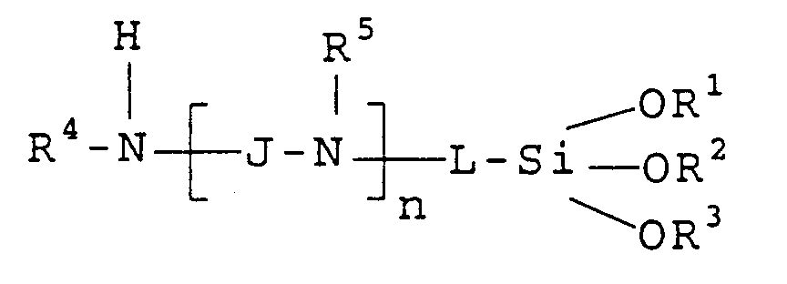 R1, R2 and R3 each independently represents a substituted or unsubstituted alkyl group having from one to 10 carbon atoms, a substituted or unsubstituted aryl group having from 5 to 10 carbon atoms, or a substituted or unsubstituted carbocyclic group having from 5 to 10 carbon atoms;R4 and R5 each independently represents hydrogen or the same groups as R1, R2 and R3;J and L each independently represents hydrocarbon linking moieties of from 1 to 12 carbon atoms; andn is 0 or a positive integer up to 6.
 - The dye-receiving element of Claim 6 wherein J and L are -CxH2x-linking moieties of from 1 to 10 carbon atoms, R1, R2 and R3 are each alkyl groups and n is 0, 1 or 2.
- The dye-receiving element of Claim 1 wherein the hydrophobic organo-oxysilane has the formula:
 R1, R2 and R3 each independently represents a substituted or unsubstituted alkyl group having from one to 10 carbon atoms, a substituted or unsubstituted aryl group having from 5 to 10 carbon atoms, or a substituted or unsubstituted carbocyclic group having from 5 to 10 carbon atoms; andR6 is a nonsubstituted alkyl group having from 1 to 10 carbon atoms, or a nonsubstituted aryl group having from 5 to 10 carbon atoms.
 - A process of forming a dye transfer image comprising:a) imagewise-heating a dye-donor element comprising a support having thereon a dye layer comprising a dye dispersed in a binder, andb) transferring a dye image to a dye-receiving element comprising a support having thereon a dye image-receiving layer to form said dye transfer image,wherein the receiving element comprises a polyolefin-coated substrate or a polyolefin substrate having thereon, in order, a subbing layer and a dye image-receiving layer, and wherein the subbing layer comprises a reaction product of a mixture ofa) an aminofunctional organo-oxysilane, andb) a hydrophobic organo-oxysilane.
- A thermal dye transfer assemblage comprising:a) a dye-donor element comprising a support having thereon a dye layer comprising a dye dispersed in a binder, andb) a dye-receiving element comprising a support having thereon a dye image-receiving layer, said dye-receiving element being in a superposed relationship with said dye-donor element so that said dye layer is in contact with said dye image-receiving layer,wherein the receiving element comprises a polyolefin-coated substrate or a polyolefin substrate having thereon, in order, a subbing layer and a dye image-receiving layer, and wherein the subbing layer comprises a reaction product of a mixture ofa) an aminofunctional organo-oxysilane, andb) a hydrophobic organo-oxysilane.
Applications Claiming Priority (2)
| Application Number | Priority Date | Filing Date | Title |
|---|---|---|---|
| US247194 | 1994-05-20 | ||
| US08/247,194 US5384304A (en) | 1994-05-20 | 1994-05-20 | Receiving element subbing layer for use in thermal dye transfer |
Publications (2)
| Publication Number | Publication Date |
|---|---|
| EP0683059A1 EP0683059A1 (en) | 1995-11-22 |
| EP0683059B1 true EP0683059B1 (en) | 1997-08-13 |
Family
ID=22933973
Family Applications (1)
| Application Number | Title | Priority Date | Filing Date |
|---|---|---|---|
| EP95106648A Expired - Lifetime EP0683059B1 (en) | 1994-05-20 | 1995-05-03 | Receiving element subbing layer for use in thermal dye transfer |
Country Status (4)
| Country | Link |
|---|---|
| US (1) | US5384304A (en) |
| EP (1) | EP0683059B1 (en) |
| JP (1) | JP3691542B2 (en) |
| DE (1) | DE69500540T2 (en) |
Families Citing this family (8)
| Publication number | Priority date | Publication date | Assignee | Title |
|---|---|---|---|---|
| DE69610958T2 (en) * | 1995-08-30 | 2001-05-23 | Eastman Kodak Co., Rochester | Stabilized dye receiving element for thermal dye transfer |
| US5585326A (en) * | 1995-12-08 | 1996-12-17 | Eastman Kodak Company | Dye-receiving element subbing layer for use in thermal dye transfer |
| US5597775A (en) * | 1996-01-16 | 1997-01-28 | Eastman Kodak Company | Dye-receiver subbing layer for thermal dye transfer |
| US5585325A (en) * | 1996-03-08 | 1996-12-17 | Eastman Kodak Company | Dye-receiver subbing layer for thermal dye transfer |
| US7910519B2 (en) * | 2007-03-05 | 2011-03-22 | Eastman Kodak Company | Aqueous subbing for extruded thermal dye receiver |
| US8222186B2 (en) * | 2009-10-20 | 2012-07-17 | Eastman Kodak Company | Thermal dye image receiver elements |
| JP6369270B2 (en) * | 2014-10-02 | 2018-08-08 | 凸版印刷株式会社 | Thermal transfer image-receiving sheet and method for producing the same |
| JP6375844B2 (en) * | 2014-10-06 | 2018-08-22 | 凸版印刷株式会社 | Thermal transfer image-receiving sheet and method for producing the same |
Family Cites Families (1)
| Publication number | Priority date | Publication date | Assignee | Title |
|---|---|---|---|---|
| US4965241A (en) * | 1989-12-11 | 1990-10-23 | Eastman Kodak Company | Thermal dye transfer receiving element with subbing layer for dye image-receiving layer |
-
1994
- 1994-05-20 US US08/247,194 patent/US5384304A/en not_active Expired - Lifetime
-
1995
- 1995-05-03 EP EP95106648A patent/EP0683059B1/en not_active Expired - Lifetime
- 1995-05-03 DE DE69500540T patent/DE69500540T2/en not_active Expired - Fee Related
- 1995-05-17 JP JP11846695A patent/JP3691542B2/en not_active Expired - Fee Related
Also Published As
| Publication number | Publication date |
|---|---|
| JP3691542B2 (en) | 2005-09-07 |
| DE69500540D1 (en) | 1997-09-18 |
| US5384304A (en) | 1995-01-24 |
| EP0683059A1 (en) | 1995-11-22 |
| DE69500540T2 (en) | 1997-12-11 |
| JPH07314927A (en) | 1995-12-05 |
Similar Documents
| Publication | Publication Date | Title |
|---|---|---|
| EP0318946B1 (en) | Process for increasing the density of images obtained by thermal dye transfer | |
| EP0268179B1 (en) | Inorganic polymer subbing layer for dye-donor element used in thermal dye transfer | |
| EP0657302B1 (en) | Thermal dye transfer dye-donor element containing transferable protection overcoat | |
| EP0228065B1 (en) | Dye-barrier and subbing layer for dye-donor element used in thermal dye transfer | |
| EP0227091B1 (en) | Dye-barrier/subbing layer for dye-donor element used in thermal dye transfer | |
| EP0659578B1 (en) | Release agent for thermal dye transfer receiving element | |
| EP0683059B1 (en) | Receiving element subbing layer for use in thermal dye transfer | |
| EP0432707B1 (en) | Thermal dye transfer receiving element with subbing layer for dye image-receiving layer | |
| EP0856417B1 (en) | Release agents for dye-donor element used in thermal dye transfer | |
| EP0340722B1 (en) | Alkyl- or aryl-amino-pyridyl- or pyrimidinyl-azo yellow dye-donor element for thermal dye transfer | |
| EP0603569B1 (en) | Thermal dye-transfer receiving element | |
| EP0733488A2 (en) | Thermal dye transfer dye-donor element containing transferable protection overcoat | |
| EP0311840B1 (en) | Polymeric binder for amino-modified silicone slipping layer for dye-donor element used in thermal dye transfer | |
| EP0649758B1 (en) | Interlayer for slipping layer in dye-donor element used in thermal dye transfer | |
| US5585326A (en) | Dye-receiving element subbing layer for use in thermal dye transfer | |
| EP0760292B1 (en) | Thermal dye transfer system with receiver containing amino groups | |
| EP0761469B1 (en) | Stabilised dye-receiving element for use in thermal dye transfer | |
| EP0733485A2 (en) | Thermal dye transfer system with a dye-receiving element comprising a reactive carbonyl group | |
| US5627129A (en) | Stabilizers for receiver used in thermal dye transfer | |
| EP0714788B1 (en) | Overcoat for thermal dye transfer receiving element | |
| US5597775A (en) | Dye-receiver subbing layer for thermal dye transfer | |
| EP0733484B1 (en) | Thermal dye transfer system with a dye-receiving element containing a reactive keto moiety | |
| EP0718118A1 (en) | Thermal dye transfer printing method | |
| US5585325A (en) | Dye-receiver subbing layer for thermal dye transfer | |
| EP0718114B1 (en) | Extruded thermal transfer dye-receiver comprising a transition metal salt of a copolymer |
Legal Events
| Date | Code | Title | Description |
|---|---|---|---|
| PUAI | Public reference made under article 153(3) epc to a published international application that has entered the european phase |
Free format text: ORIGINAL CODE: 0009012 |
|
| AK | Designated contracting states |
Kind code of ref document: A1 Designated state(s): DE FR GB |
|
| 17P | Request for examination filed |
Effective date: 19960520 |
|
| GRAG | Despatch of communication of intention to grant |
Free format text: ORIGINAL CODE: EPIDOS AGRA |
|
| 17Q | First examination report despatched |
Effective date: 19960809 |
|
| GRAH | Despatch of communication of intention to grant a patent |
Free format text: ORIGINAL CODE: EPIDOS IGRA |
|
| GRAH | Despatch of communication of intention to grant a patent |
Free format text: ORIGINAL CODE: EPIDOS IGRA |
|
| GRAA | (expected) grant |
Free format text: ORIGINAL CODE: 0009210 |
|
| AK | Designated contracting states |
Kind code of ref document: B1 Designated state(s): DE FR GB |
|
| REF | Corresponds to: |
Ref document number: 69500540 Country of ref document: DE Date of ref document: 19970918 |
|
| ET | Fr: translation filed | ||
| PLBE | No opposition filed within time limit |
Free format text: ORIGINAL CODE: 0009261 |
|
| STAA | Information on the status of an ep patent application or granted ep patent |
Free format text: STATUS: NO OPPOSITION FILED WITHIN TIME LIMIT |
|
| 26N | No opposition filed | ||
| PGFP | Annual fee paid to national office [announced via postgrant information from national office to epo] |
Ref country code: FR Payment date: 20000504 Year of fee payment: 6 |
|
| PGFP | Annual fee paid to national office [announced via postgrant information from national office to epo] |
Ref country code: DE Payment date: 20000531 Year of fee payment: 6 |
|
| REG | Reference to a national code |
Ref country code: GB Ref legal event code: IF02 |
|
| PG25 | Lapsed in a contracting state [announced via postgrant information from national office to epo] |
Ref country code: FR Free format text: LAPSE BECAUSE OF NON-PAYMENT OF DUE FEES Effective date: 20020131 |
|
| PG25 | Lapsed in a contracting state [announced via postgrant information from national office to epo] |
Ref country code: DE Free format text: LAPSE BECAUSE OF NON-PAYMENT OF DUE FEES Effective date: 20020301 |
|
| PGFP | Annual fee paid to national office [announced via postgrant information from national office to epo] |
Ref country code: GB Payment date: 20050406 Year of fee payment: 11 |
|
| PG25 | Lapsed in a contracting state [announced via postgrant information from national office to epo] |
Ref country code: GB Free format text: LAPSE BECAUSE OF NON-PAYMENT OF DUE FEES Effective date: 20060503 |
|
| GBPC | Gb: european patent ceased through non-payment of renewal fee |
Effective date: 20060503 |