EP0683055A2 - Méthode d'impression avec utilisation économique du matériau de transfert - Google Patents
Méthode d'impression avec utilisation économique du matériau de transfert Download PDFInfo
- Publication number
- EP0683055A2 EP0683055A2 EP95300931A EP95300931A EP0683055A2 EP 0683055 A2 EP0683055 A2 EP 0683055A2 EP 95300931 A EP95300931 A EP 95300931A EP 95300931 A EP95300931 A EP 95300931A EP 0683055 A2 EP0683055 A2 EP 0683055A2
- Authority
- EP
- European Patent Office
- Prior art keywords
- carrier
- print head
- substrate
- printing
- Prior art date
- Legal status (The legal status is an assumption and is not a legal conclusion. Google has not performed a legal analysis and makes no representation as to the accuracy of the status listed.)
- Granted
Links
- 238000007639 printing Methods 0.000 title claims abstract description 187
- 238000000034 method Methods 0.000 title claims abstract description 42
- 239000000463 material Substances 0.000 title description 2
- 239000000758 substrate Substances 0.000 claims abstract description 127
- 238000010438 heat treatment Methods 0.000 claims description 20
- 230000008021 deposition Effects 0.000 claims description 2
- 230000004886 head movement Effects 0.000 claims description 2
- 238000007651 thermal printing Methods 0.000 description 6
- 239000011888 foil Substances 0.000 description 4
- 239000011159 matrix material Substances 0.000 description 4
- 230000005540 biological transmission Effects 0.000 description 3
- 230000000694 effects Effects 0.000 description 3
- 238000002360 preparation method Methods 0.000 description 2
- 238000010023 transfer printing Methods 0.000 description 2
- 230000015572 biosynthetic process Effects 0.000 description 1
- 238000007796 conventional method Methods 0.000 description 1
- 238000012986 modification Methods 0.000 description 1
- 230000004048 modification Effects 0.000 description 1
- 239000005022 packaging material Substances 0.000 description 1
- 229920000573 polyethylene Polymers 0.000 description 1
- 238000000926 separation method Methods 0.000 description 1
Images


Classifications
-
- B—PERFORMING OPERATIONS; TRANSPORTING
- B41—PRINTING; LINING MACHINES; TYPEWRITERS; STAMPS
- B41J—TYPEWRITERS; SELECTIVE PRINTING MECHANISMS, i.e. MECHANISMS PRINTING OTHERWISE THAN FROM A FORME; CORRECTION OF TYPOGRAPHICAL ERRORS
- B41J17/00—Mechanisms for manipulating page-width impression-transfer material, e.g. carbon paper
- B41J17/02—Feeding mechanisms
- B41J17/12—Special adaptations for ensuring maximum life
-
- B—PERFORMING OPERATIONS; TRANSPORTING
- B41—PRINTING; LINING MACHINES; TYPEWRITERS; STAMPS
- B41J—TYPEWRITERS; SELECTIVE PRINTING MECHANISMS, i.e. MECHANISMS PRINTING OTHERWISE THAN FROM A FORME; CORRECTION OF TYPOGRAPHICAL ERRORS
- B41J33/00—Apparatus or arrangements for feeding ink ribbons or like character-size impression-transfer material
- B41J33/14—Ribbon-feed devices or mechanisms
- B41J33/54—Ribbon-feed devices or mechanisms for ensuring maximum life of the ribbon
Definitions
- This invention relates to a method of printing.
- a method of printing utilising a printing head having a plurality of printing elements each of which is operable to transfer a pixel of print medium from a carrier onto an adjacent substrate comprising the steps of causing relative movement between the substrate and carrier, and the print head, such that the print head moves relative to an area of the carrier from a start position to an end position whilst utilising some or all of the printing elements to transfer a first set of pixels of print medium from the area of the carrier onto the substrate, causing relative movement between the print head and the carrier to replace the print head at the start position, causing relative movement between the carrier and the substrate such that fresh substrate is presented adjacent to the area of the carrier, and causing relative movement between the fresh substrate and the carrier, and the print head, such that the print head moves relative to the area of the carrier again from the start position to the end position whilst utilising some or all of the printing elements, to transfer a second set of pixels of print medium from the area of the carrier, onto the adjacent fresh substrate.
- print density is determined by dot resolution.
- the invention offers a way for a user to save the cost of thermal printing ribbon or foil, or other carrier and print medium where the relatively high density print which can be obtained by at least the higher resolution dot based printing systems, is not required.
- fresh substrate we mean an entirely fresh substrate, such as a different label, or a further part of the same substrate, onto which pixels of print medium have not previously been transferred from the carrier.
- the printing head may be moved e.g. laterally, away from the carrier and substrate, and held a short distance away from the carrier whilst the carrier and/or substrate are moved in preparation for the next printing operation, and then moved e.g. laterally, back towards the carrier and substrate.
- a first set only of the printing elements is employed to transfer the first set of pixels of print medium onto the substrate.
- a second set of printing elements is employed to transfer the second set of pixels of print medium onto the substrate.
- two separate substrates or separate areas of substrate can be printed for example, with the same information, but the apparatus only consumes one area of ribbon or foil.
- the method may be repeated several times for the same area of carrier, with each relative movement between substrate and carrier, and the print head, utilising different printing elements to transfer different pixels of print medium onto substrate.
- the printing elements may be used thus ensuring that, even if there is some misalignment between the printing elements and the remaining pixels of print medium, the remaining pixels of print medium will be transferred.
- printing elements are utilised to transfer pixels of print medium from the area of the carrier onto the substrate
- printing elements are utilised to transfer pixels of print medium from the area of the carrier onto the fresh substrate such that the pixels of print medium are transferred from different pixel positions of the carrier to the pixel positions from which the print medium was transferred during the previous relative movement between the substrate and carrier, and the print head.
- the printing elements may be used such that printing elements are utilised in pixel positions at least partially coincidental with pixel positions of the carrier from which print medium was transferred in a previous printing operation.
- the relative movement between the substrate and carrier, and the print head is produced by movement of the print head whilst the substrate and carrier are held stationary.
- the relative movement between the substrate and carrier, and the print head is produced by movement of the substrate and carrier whilst the print head is held stationary.
- the invention is particularly but not exclusively applicable to thermal transfer printing, where the print medium comprises inkcarried on a carrier comprising a continuous backing web, and the printing elements are energised to produce heat to transfer pixels of ink from the carrier onto a substrate.
- printing elements there are typically at least six, commonly eight or twelve or more printing elements per millimetre of printing head, arranged in a single line array.
- the printing elements may, however, be arranged in a multiple line, or other non-single line array.
- the invention may be applied to any other dot based printing system such as a dot matrix printer which utilises a woven ribbon as a carrier for ink and where printing elements are arranged in an array.
- a dot matrix printer which utilises a woven ribbon as a carrier for ink and where printing elements are arranged in an array.
- a printing apparatus comprising a print head operable to transfer pixels of print medium from a carrier onto an adjacent substrate, means to maintain the print head during printing, stationary, and to move the carrier and substrate in a first direction past the print head from a start position to an end of print position over an area of the carrier and means to cause the carrier, after a first printing operation, to move relative to the print head in a second direction generally opposite to the first direction and to present fresh substrate adjacent to the print head so that in a subsequent printing operation, the fresh substrate is moved with carrier, in the first direction past the printing head.
- a thermal printer having a print head with an array of heating elements, and a print ribbon with a layer of thermally sensitive ink for deposition on a print area of a medium to be printed, wherein the method comprises:
- the method may include using a printer in which the print head is movable relatively to the print ribbon and generally parallel to the surface of the ribbon and has an array of heating elements extending laterally with respect to the direction of print head movement, and moving the print head in a first stroke whilst selectively energizing the first set of heating elements, subsequently moving the print medium, and then moving the print head in a second stroke whilst energizing the second set of heating elements, using the same ribbon portion for both print head strokes.
- a method may further include using a printer in which the print head is movable relatively to the print ribbon and has a linear array of heating elements extending laterally with respect to the direction of movement of the print head, and moving the print head in a first stoke relative to the print ribbon and the print area of the print medium, controlling the print head to energize the first set of heating elements during the first stroke, thereby to heat the first portion of the ribbon and to deposit ink onto the print medium, controlling the print head to energize the second set of heating elements during a subsequent print stroke to heat the same first ribbon portion so as to use ink on the first ribbon portion not used in a previous print stroke, and displacing the ribbon after the print strokes in which alternate heating elements are used so that the print head may heat a second portion o f the ribbon during a subsequent specific number of print strokes.
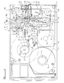
- a printing apparatus 10 comprising a print head assembly 11 which mounts a plurality of individually energisable thermal printing elements, preferably provided on an edge of the print head assembly 11, in a single line array.
- the print head assembly 11 is movable relative to carrier, being a web 12 which carries print medium comprising ink, whilst the thermal printing elements are individually selectively energised under computer control, wherein the elements will become hot, thus to cause pixels of ink to be removed from the web 12 and deposited onto a substrate (not shown) to the right hand side of the apparatus 10 as seen in figure 1.
- the substrate may for example be a label which is subsequently applied to an article, or packaging material, or may be the article itself, which substrate moves past the printing apparatus 10 and is temporarily halted at the printing apparatus 10 whilst printing thereon is effected.
- the information usually is, one or more alpha-numeric characters, to indicate for example, a sell-by date.
- the or each such character is defined by a plurality of pixels of print medium i.e. ink, transferred from the web 12 or other carrier by the energised printing elements of the printing head assembly 11 as the print head assembly 11 is moved relative to the carrier and substrate.
- the web 12 carrying the ink is provided on a supply spool 14 carried on a hub 15, the web 12 passing around a web guide path comprising idler rollers 16,17,18, around a further roller 19 between the roller 19 and a drive roller R and then on to a take up spool mounted on a hub 20.
- the drive roller R and take up spool are driven, as hereinafter explained, from a motive means 21 which is in this example, a stepper motor.
- the hub 15 and hence spool 14 provides some resistance to web 12 being paid out therefrom, this being provided by a friction means being a clutch material W and a spring S configured as is well known in the art.
- the take up spool is also mounted on a hub 20 having a similar friction means.
- the print head assembly 11 is driven for movement relative to the web 12 by the motor 21 via a transmission.
- the transmission comprises a pair of generally parallel spaced apart flexible drive members comprising belts 23,24, which are entrained respectively about pairs of rollers 25,26, and rollers 27,28.
- Drive shaft 30 has secured to it, a gear 30a which meshes with a gear 30b on a shaft L on which roller R is provided.
- the print head assembly 11 is of generally rectangular configuration, and is secured to a mounting structure T which is clamped at screws 36,37, (see figure 3) to the belts 23,24.
- drive is transmitted from the drive shaft 33 of the motor to each of the belts 23,24, via the shaft 31, and hence the print head assembly 11 is caused to move either in the direction indicated by arrow A, relative to the web 12, or an opposite direction depending upon the sense of rotation of the output shaft 33 of the motor 21.
- the structure T comprises a slider element V and a bearing B which is fixed relative to the print head assembly 11 and is slidable relative to the slider element V. Hence the print head assembly 11 can slide in the direction of arrow B and in an opposite direction, relative to the slider element V.
- the print head assembly 11 also carries at its rear edge, a guide roller 44 which is rotatable about a generally vertical axis 45 transverse to the direction A of movement of the print head assembly 11 during printing.
- the roller 44 bears on a generally horizontal post 46 of generally circular cross section, the post being mounted via a lever arm 47 for rotation about a horizontal axis 48 generally parallel to but spaced from the post 46, on a bearing 50 which is fixed relative to a body of the printing assembly 10.
- the print head assembly 11 moves from side to side, in the direction of arrow A or oppositely, the print head assembly 11 is guided for movement via the guide roller 44 and post 46.
- a strong spring 47a is provided between the post 46 and a frame part P of the apparatus 10 to bias the post 46 about axis 48 away from the print head. assembly 11.
- the print head assembly 11 carries a hook formation H which engages with post 46 so that as the post 46 moves in the direction generally opposite to that of arrow B, the print head assembly 11 is moved with it, and slides relative to the mounting structure T.
- the amount that the post 46 can be moved by the spring 47a is restricted by means of an air cylinder 50 which is positioned behind the post 46.
- the print head assembly 11 is shown in a start position spaced away from a substrate, but with the web 12 carrying the ink, entrained over an edge of the print head assembly 11 mounting the thermal printing elements.
- the print head assembly 11 is moved in a direction indicated by arrow B, i.e. laterally, which is transverse to the direction of movement of the print head assembly 11 during printing, as indicated by arrow A.
- Movement of the post 46 and hence of the print head assembly 11 in direction B is achieved by means of the air cylinder 50 and its piston 51, which, when actuated, rotates the guide post 46 about axis 48, thus to urge the print head assembly 11 towards the substrate, against the restoring force of the spring 47a.
- the piston 51 is arranged to retain the print head assembly 11 in its extended position against the restoring force of the springs 47a, whilst the print head assembly 11 moves from the beginning, to end of printing positions in direction of arrow A, to effect printing on the substrate.
- the piston 51 is deactuated and the print head assembly 11 is moved in an opposite direction to arrow B by the restoring force of the spring 47a away from the substrate and, by actuating the motor 21 in an opposite sense of rotation, the print head assembly 11 is moved back to the start position shown in the drawings in a direction opposite to the direction of arrow A.
- the hub 20 of the take up spool carried by hub 20 is driven from the motor 21 via a drive belt 80 shown in dotted lines in figure 2, which is fixed to rotate with the drive roller R.
- a mechanical one-way clutch which permits the shaft L to rotate relative to the roller R as the stepper motor 21 rotates in one sense of rotation (clockwise in figure 2) during a printing operation.
- the web 12 and take-up spool 20 remain stationary during a printing operation as the extended print head 11 moves downwardly as seen in figure 2.
- Aone-way clutch suitable for this purpose is well known in itself and is a purely mechanical unit.
- the spools 14 and spool carried by hub 20 as well as the drive roller R (but not its shaft L) and idler rollers 19, 18 and 17 are carried by a cassette 55 which can be removed from the body of the printing apparatus 10 to facilitate replenishing the printing apparatus 10 with web 12.
- the web guide path includes a peeler bar P' behind which the web 12 passes immediately after passing over the print head assembly 11, the bar P' being operable to ensure proper separation of ink deposited on the substrate, and remaining web 12.
- the belt 41 is maintained under tension by means of a tensioning roller 59 and the belts 23,24, can also be kept under constant tension by tensioning rollers 60.
- a micro switch 61 which feeds power to the stepper motor 21 is tripped so that there is no risk of the mechanism of the printing apparatus 10 being actuated without the cassette 55 being in position.
- the amount of movement of the print head assembly 11 in a direction opposite to that of arrow A i.e. the return movement, is restricted by means of a microswitch carried on a clamp means 63 which senses the print head assembly 11 when returned to its start position, immediately to stop motor 21.
- the assembly 11 is able to float to a smaller degree about the central axis of post 46.
- the roller 44 mounted at the rear of the printing assembly 11 engages with the post 46 to restrict other movements.
- the assembly 11 can move slightly about the central axis of post 46 as the print head assembly 11 is moved towards the substrate by the actuator 50 to accommodate such slight misalignment.
- the printing apparatus described above may be operated by a method in accordance with the first invention as follows.
- the print head assembly 11 may comprise at least six, but possibly eight, twelve, or more energisable printing elements per millimetre width of the print head assembly 11, with all of the energisable print elements arranged in a single line array across the printing head assembly 11.
- a first set only of the printing elements may be utilised on a first printing operation. For example, every alternate printing element may be utilised whilst the print head assembly 11 is traversed over or otherwise moves over an area of the web 12 from its start to end of print positions to transfer pixels of ink from the web 12 onto the substrate.
- an alpha-numeric character or a plurality of such characters may be printed on the substrate.
- the print density will obviously be less overall than if all the printing elements of the print head assembly 11 were used during printing. Whereas this might not be acceptable for printing machine-readable information such as a bar code, where the information printed is for example a sell-by date comprising a plurality of alpha-numeric characters, a human readerwill have little difficulty in reading the information.
- the print head assembly 11 is moved as hereinbefore described relative to the web 12 back to the start of print position, but the electronically operated clutch between the gear 30b and its shaft L is operated so as to isolate the roller R so that the web 12 is not advanced.
- the substrate may be advanced, or an entirely fresh substrate may be presented adjacent to the same area of the web 12 which was traversed by the print head assembly 11 immediately previously.
- the print head assembly 11 may then be operated to traverse the same area of the web 12, but different printing elements are utilised during printing to transfer pixels of ink from the web 12 onto the substrate.
- the take up spool 20 may have a slipping clutch which permits differential movement between the spool 20 and the drive roller R as the spool 20 becomes filled with used web 12.
- the amount of web 12 utilised for printing will be reduced by half, in this example, assuming that the web 12 is advanced after the print head assembly 11 has relatively traversed the web 12 for a second time.
- the individual printing elements may have a first power provided to them, whereas in a subsequent printing operation using the same area of ink carrier, when all of the printing elements are energized selectively, a second reduced power may be provided to each of the printing elements when they are energised.
- each of the printing elements may be utilised to transfer pixels of print medium i.e. ink, from the web 12 onto the substrate.
- the printing elements may only be operated for certain pixel positions (rows) between the start and end of printing positions.
- the print density will be lower than if the printing elements were all actuated in all pixel positions, but again, where the information to be printed is intended for a human reader, the print density will in most instances be sufficient for the human reader to read the information.
- each of the printing elements may again be utilised, but by ensuring that each printing element is not operated when in the same pixel position that the printing element was previously operated during the first traverse of the print head 11 relative to the web 12, pixels of ink are transferred from different pixel positions of the web 12 to the pixel positions from which ink was transferred during the previous traverse of the print head assembly relative to that area of web 12.
- the method of the invention may cause the print head assembly 11 to traverse or otherwise move relative to the carrier for more than two times, provided that for each such movement during printing, no printing element is operated in the same pixel position between the start and end of printing positions, that the printing element was operated in a previous printing movement of the print head 11 relative to the same area of the web 12.
- all the printing elements may be used in all possible pixel positions to ensure that an adequate amount of ink is transferred onto the fresh substrate in the event of any slight misalignment between the web 12 and the printing elements.
- the printing apparatus 10 may be used in other orientations to that described, as appropriate to the position and orientation of the substrate.
- the printing apparatus 10 described has been of the type which utilises a web 12 carrying ink which is deposited by means of thermal printing elements onto a substrate, the invention may be applied to any other printing apparatus having a plurality of selectively operable printing elements to effect printing, such as a 24 dot matrix printer.
- the print head assembly 11 may incorporate an array being a single line of printing elements as described, or an array being a matrix i.e. multiple lines of such elements.
- the print head assembly 11 is carried via the mounting structures T by three drive belts 23,24,41, in another arrangement, less than three drive belts, or more than three drive belts, may be provided.
- any other suitable endless loop members such as chains, could be used to provide a transmission and mounting for the print head assembly 11, or indeed any other suitable flexible or rigid drive member or members which is/are able to provide drive to, and a means of mounting the print head assembly 11, could be used.
- single stepper motor 21 may be used as a motive means for the printing apparatus 10, with suitable logic control e.g. utilising a computer, if desired more than one stepper motor 21 or other motive means may be provided.
- a separate motor may be provided to drive the drive roller R and take up spool 20 for the web 12.
- Any alternative means to the piston and cylinder arrangement 50 for effecting movement of the print head assembly 11 towards the substrate, may be provided.
- the invention may be applied to an apparatus of the type in which the print head is at a fixed position, and the carrier carrying print medium, and the substrate are together moved relative to the print head during printing.
- the carrier may be arranged to be moved back relative to the print head assembly whilst fresh substrate is presented adjacent that area of the carrier, and the carrier and fresh substrate is traversed past the fixed print head assembly a second, and where appropriate, further, times.
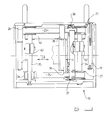
- FIG 4 a partial view of one embodiment of such an apparatus 100 shows web path and drive components.
- a web 112 carrying the ink is provided on a supply spool 114 carried on a hub 115, the web 112 passing around a web guide path comprising guide roller 116, print head roller 117 against which the print head 111 exerts a force during printing, guide roller 118, web drive roller 119, which is operable to drive the web 112 and is solely responsible for the amount of web 112 movement in either direction, as hereinafter explained.
- the web is then guided on to a take-up spool 120 carried on a hub 121.
- Supply spool 114, web drive roller 119, and take-up spool 120 are driven from a single motive means 122, which in this example is a two-way stepper motor, via a drive and timing belt 123.
- Spool 114 is driven through a one-way clutch and slip clutch and spool 120 is driven through a one way clutch and slip clutch, the one way clutches operating in tandem such that the two clutches are operable so that when the stepper motor 122 is operated so as to move the timing belt 122 in a clockwise direction as seen in figure 4, the take up spool 120 is driven, whilst spool 114 is not driven.
- web 112 may be paid out from the supply spool 114 and taken up onto spool 120.
- stepper motor 122 is operated so as to move the timing belt 123 in an anti-clockwise direction as seen in figure 4, the supply spool 114 is driven so as to rotate anticlockwise and take-up web 112 onto it, whilst spool 120 is not driven and web 112 can be paid out from spool 120 for a purpose hereinafter described.
- slip clutches are provided for each of these spools 114 and 120 to accommodate differential movement between the spools 114 and 120 as increasingly, web is fed out from the supply spool 114 onto the take-up spool 120.
- the slip clutches also provide slight resistance (drag) when the respective spools 114,120, are paying out web 112.
- At least the one-way clutches may be electrically operated, although simple mechanical devices are adequate to perform this function.
- a substrate 124 is supplied from a supply spool (not shown) and passes between the web 112 and print head roller 117. Particularly if the substrate 124 consists of labels on a web, the path can continue around the print head drive roller 117, around a nip roller 125 and a guide roller 126. If the substrate is of another form such as polythene film, the path may continue in substantially the same direction, as indicated by chain line 127.
- the substrate 124 is driven by a second motive means (not shown) so that the substrate 124 moves in synchronism with the web 112 past the print head assembly which is indicated by arrow 111.
- Movement of the substrate may be continuous or intermittent as desired.
- the stepper motor 122 drives the timing belt 123 in a clockwise direction
- the one-way clutch and slip clutch of spool 114 offers only slip/drag resistance to clockwise rotation and spool 114 acts as a supply spool.
- the one way clutch and slip clutch of spool 120 allow spool 120 to be driven with web drive roller 119 in a clockwise direction so that the web 112 is taken up on to spool 120.
- the slip clutch on the take-up spool 120 the actual amount of web 112 which traverses the print head 111, is governed entirely by the web drive roller 119 which is directly driven via belt 123 from the motor 122, and preferably comprises a rubber coated roller which gives good stiction with the web 112.
- the print head assembly 111 After completion of the first printing operation using an area of web 112, the print head assembly 111 is pulled back a small distance, in the order of half to one millimetre, from the web 112 in the direction of arrow C, thus releasing the pressure exerted on roller 117 during printing.
- This is achieved as the print head assembly 111 is mounted on an arm 130 which is rotatable about axis 130a of idler roller 16.
- the arm 130 is spring biased by a spring wound about the central axis 130 of idler roller 116, or otherwise, to urge the arm 130 away from the reaction roller 117.
- the arm 130 and hence the print head 111 can be moved against the force of that spring by a pneumatically operated actuator which acts on the arm 130 in the direction of arrow D.
- a pneumatically operated actuator which acts on the arm 130 in the direction of arrow D.
- the substrate 124 is then driven on so that an area of fresh substrate is provided adjacent to the print head 111.
- the stepper motor 122 drives the timing belt 123 in an anticlockwise direction, the one way and slip clutches of spool 120 offering only slip/drag resistance to web 112 being paid out from spool 120 so that spool 120 acts as a supply spool whilst the one-way and slip clutches of spool 114 causes the spool 114 to be driven so that spool 114 acts as a pick-up spool.
- the amount of web 112 driven is again governed by the web drive roller 119.
- the operation of the two-way stepper motor 122 and the second stepper motor which drives the substrate 124, must be accurately co-ordinated. This may be achieved by mechanical means but is most conveniently provided by means of computer control. Alternatively, the stepper motor 122 may be arranged to drive the substrate.
- the print head assembly 112 where the printing elements are energised thermally to transfer pixels of print medium i.e. ink from the carrier web 112 onto the substrate
- control is preferably achieved by a computer, together with the relative movements of the print head and/or carrier and/or substrate as appropriate to cause either selective printing elements to be energised during each print operation, or for all or substantially all of the printing elements to be used during each printing operation but the printing elements are only energised in selected pixel positions during each printing operation to enable the same area of web 112 or other carrier respectively to be used to print information, by a method as described in detail above with reference to the embodiment of figures 1 to 3.
- the mechanism of figure 4 although ideal for performing a method of the first aspect of the invention, may be used in other apparatus where it is desired to move carrier in an appropriate direction to the direction the carrier and substrate move during printing.
Landscapes
- Electronic Switches (AREA)
- Ink Jet (AREA)
Applications Claiming Priority (4)
| Application Number | Priority Date | Filing Date | Title |
|---|---|---|---|
| GB9410273A GB9410273D0 (en) | 1994-05-20 | 1994-05-20 | Printing apparatus |
| GB9410273 | 1994-05-20 | ||
| GB9419469A GB2289441B (en) | 1994-05-20 | 1994-09-27 | Method of printing |
| GB9419469 | 1994-09-27 |
Publications (3)
| Publication Number | Publication Date |
|---|---|
| EP0683055A2 true EP0683055A2 (fr) | 1995-11-22 |
| EP0683055A3 EP0683055A3 (fr) | 1996-11-06 |
| EP0683055B1 EP0683055B1 (fr) | 2000-05-24 |
Family
ID=26304925
Family Applications (1)
| Application Number | Title | Priority Date | Filing Date |
|---|---|---|---|
| EP95300931A Expired - Lifetime EP0683055B1 (fr) | 1994-05-20 | 1995-02-15 | Méthode d'impression avec utilisation économique du matériau de transfert |
Country Status (4)
| Country | Link |
|---|---|
| EP (1) | EP0683055B1 (fr) |
| AU (1) | AU693532B2 (fr) |
| DE (1) | DE69517089T2 (fr) |
| ES (1) | ES2121707T3 (fr) |
Cited By (7)
| Publication number | Priority date | Publication date | Assignee | Title |
|---|---|---|---|---|
| WO1996032258A1 (fr) * | 1995-04-12 | 1996-10-17 | Prestek Limited | Procede d'impression |
| WO1997036751A1 (fr) * | 1996-03-29 | 1997-10-09 | Markem Technologies Limited | Procede d'impression |
| GB2315244A (en) * | 1996-03-29 | 1998-01-28 | Markem Tech Ltd | Method of printing |
| US5815193A (en) * | 1997-12-03 | 1998-09-29 | Illinois Tool Works Inc. | Printing with sealable housing and adjustable back-up plate and method therefor |
| US5873662A (en) * | 1997-12-03 | 1999-02-23 | Illinois Tool Works Inc. | Printer with dancer arm and reel brake and method therefor |
| US6019527A (en) * | 1996-10-15 | 2000-02-01 | Itw Limited | Method of operating a thermal printer |
| US7150572B2 (en) | 2000-09-11 | 2006-12-19 | Zippher Limited | Tape drive and printing apparatus |
Families Citing this family (2)
| Publication number | Priority date | Publication date | Assignee | Title |
|---|---|---|---|---|
| GB2448302B (en) | 2007-03-07 | 2009-04-08 | Zipher Ltd | Tape drive |
| WO2008119927A1 (fr) | 2007-03-31 | 2008-10-09 | Zipher Limited | Dérouleur de bande |
Citations (4)
| Publication number | Priority date | Publication date | Assignee | Title |
|---|---|---|---|---|
| JPS6052386A (ja) * | 1983-08-31 | 1985-03-25 | Copal Co Ltd | 熱転写式プリンタのインクフィルム送り方法 |
| DE3608360A1 (de) * | 1986-03-13 | 1987-09-17 | Olympia Ag | Mehrfarbendrucker in schreib- oder aehnlichen bueromaschinen |
| JPS62246773A (ja) * | 1986-04-18 | 1987-10-27 | Brother Ind Ltd | プリンタ |
| US5017028A (en) * | 1987-04-28 | 1991-05-21 | Compular Limited | Substrate clamping apparatus for a thermal printer |
Family Cites Families (2)
| Publication number | Priority date | Publication date | Assignee | Title |
|---|---|---|---|---|
| US4712115A (en) * | 1985-05-10 | 1987-12-08 | Kabushiki Kaisha Toshiba | Thermal-transfer printer |
| US4705405A (en) * | 1986-04-09 | 1987-11-10 | Cca, Inc. | Mixing apparatus |
-
1995
- 1995-02-15 EP EP95300931A patent/EP0683055B1/fr not_active Expired - Lifetime
- 1995-02-15 DE DE1995617089 patent/DE69517089T2/de not_active Expired - Lifetime
- 1995-02-15 ES ES95300931T patent/ES2121707T3/es not_active Expired - Lifetime
- 1995-05-16 AU AU20085/95A patent/AU693532B2/en not_active Expired
Patent Citations (4)
| Publication number | Priority date | Publication date | Assignee | Title |
|---|---|---|---|---|
| JPS6052386A (ja) * | 1983-08-31 | 1985-03-25 | Copal Co Ltd | 熱転写式プリンタのインクフィルム送り方法 |
| DE3608360A1 (de) * | 1986-03-13 | 1987-09-17 | Olympia Ag | Mehrfarbendrucker in schreib- oder aehnlichen bueromaschinen |
| JPS62246773A (ja) * | 1986-04-18 | 1987-10-27 | Brother Ind Ltd | プリンタ |
| US5017028A (en) * | 1987-04-28 | 1991-05-21 | Compular Limited | Substrate clamping apparatus for a thermal printer |
Non-Patent Citations (3)
| Title |
|---|
| IBM TECHNICAL DISCLOSURE BULLETIN, vol. 31, no. 10, March 1989, NEW YORK US, pages 235-237, XP000119067 NN: "Ribbon-saving technique for APA printers." * |
| PATENT ABSTRACTS OF JAPAN vol. 12, no. 120 (M-685), 14 April 1988 & JP 62 246773 A (T. KIYOSHI), 27 October 1987, * |
| PATENT ABSTRACTS OF JAPAN vol. 9, no. 183 (M-400) [1906] , 30 July 1985 & JP 60 052386 A (K. OKABE), 25 March 1985, * |
Cited By (22)
| Publication number | Priority date | Publication date | Assignee | Title |
|---|---|---|---|---|
| US5846002A (en) * | 1995-04-12 | 1998-12-08 | Prestek Limited | Method of printing |
| WO1996032258A1 (fr) * | 1995-04-12 | 1996-10-17 | Prestek Limited | Procede d'impression |
| US5971634A (en) * | 1995-04-12 | 1999-10-26 | Prestek Limited | Method of printing |
| US6247859B1 (en) | 1996-03-29 | 2001-06-19 | Markem Technologies Limited | Method of printing in which the print head and print ribbon move simultaneously in the same direction |
| WO1997036751A1 (fr) * | 1996-03-29 | 1997-10-09 | Markem Technologies Limited | Procede d'impression |
| GB2315244A (en) * | 1996-03-29 | 1998-01-28 | Markem Tech Ltd | Method of printing |
| CN1116179C (zh) * | 1996-03-29 | 2003-07-30 | 马肯姆技术有限公司 | 印刷方法及其设备 |
| GB2315244B (en) * | 1996-03-29 | 1999-09-15 | Markem Tech Ltd | Method of printing |
| US6019527A (en) * | 1996-10-15 | 2000-02-01 | Itw Limited | Method of operating a thermal printer |
| US5873662A (en) * | 1997-12-03 | 1999-02-23 | Illinois Tool Works Inc. | Printer with dancer arm and reel brake and method therefor |
| US5815193A (en) * | 1997-12-03 | 1998-09-29 | Illinois Tool Works Inc. | Printing with sealable housing and adjustable back-up plate and method therefor |
| US7150572B2 (en) | 2000-09-11 | 2006-12-19 | Zippher Limited | Tape drive and printing apparatus |
| US7682094B2 (en) | 2000-09-11 | 2010-03-23 | Zipher Limited | Tape drive and printing apparatus |
| US7722268B2 (en) | 2000-09-11 | 2010-05-25 | Zipher Limited | Tape drive and printing apparatus |
| US7748917B2 (en) | 2000-09-11 | 2010-07-06 | Zipher Limited | Tape drive and printing apparatus |
| US7753605B2 (en) | 2000-09-11 | 2010-07-13 | Zipher Limited | Tape drive and printing apparatus |
| US8007190B2 (en) | 2000-09-11 | 2011-08-30 | Zipher Limited | Tape drive and printing apparatus |
| US8096715B2 (en) | 2000-09-11 | 2012-01-17 | Zipher Limited | Tape drive and printing apparatus |
| US8221009B2 (en) | 2000-09-11 | 2012-07-17 | Zipher Limited | Tape drive and printing apparatus |
| US8221010B2 (en) | 2000-09-11 | 2012-07-17 | Zipher Limited | Tape drive and printing apparatus |
| US8328441B2 (en) | 2000-09-11 | 2012-12-11 | Videojet Technologies (Nottingham) Limited | Tape drive and printing apparatus |
| US8591127B2 (en) | 2000-09-11 | 2013-11-26 | Videojet Technologies (Nottingham) Limited | Tape drive and printing apparatus |
Also Published As
| Publication number | Publication date |
|---|---|
| DE69517089T2 (de) | 2000-11-02 |
| EP0683055A3 (fr) | 1996-11-06 |
| AU2008595A (en) | 1995-11-30 |
| ES2121707T3 (es) | 2000-07-16 |
| EP0683055B1 (fr) | 2000-05-24 |
| DE69517089D1 (de) | 2000-06-29 |
| AU693532B2 (en) | 1998-07-02 |
| ES2121707T1 (es) | 1998-12-16 |
Similar Documents
| Publication | Publication Date | Title |
|---|---|---|
| US5908251A (en) | Method of printing | |
| US4432830A (en) | Label printer having selectable label stock paths | |
| EP0765221B1 (fr) | Procede d'impression | |
| CN101300138B (zh) | 身份证件加工设备及使用方法 | |
| EP0451830B1 (fr) | Appareil d'impression | |
| CN1147791A (zh) | 热敏式图形印刷的方法和系统 | |
| US4205770A (en) | Selective feeding of record media | |
| EP0830251B1 (fr) | Appareil d'impression couleur double face et ensemble de support reversible de tetes d'impression | |
| EP0683055B1 (fr) | Méthode d'impression avec utilisation économique du matériau de transfert | |
| EP0516756A4 (en) | Apparatus for printing including slide mechanism | |
| EP1000756B1 (fr) | Méthode d'impression | |
| EP0556066B1 (fr) | Dispositif de commande du mouvement d'une tête d'impression | |
| US6247859B1 (en) | Method of printing in which the print head and print ribbon move simultaneously in the same direction | |
| GB2424853A (en) | Method of printing in which the printhead moves in a direction opposite to the feed direction of the substrate | |
| EP0559232B1 (fr) | Protection du cylindre d'appui dans un système d'impression thermique sans marge | |
| US6031555A (en) | Color printer having a printing film conserving mechanism | |
| EP0774360B1 (fr) | Appareil d'impression d'images graphiques sur des matériaux en feuille avec une cassette de ruban à tension constante | |
| EP0945273B1 (fr) | Méthode d'impression | |
| JPH01502175A (ja) | カード取出し装置 | |
| GB2376662A (en) | Printer with a ribbon feed path including a resiliently mounted low inertia ribbon store disposed between a supply spool and a take-up spool | |
| WO1994026526A1 (fr) | Appareil d'imprimerie | |
| GB2311492A (en) | A printer having a printhead movable between a parked position and a printing position and a motor for simultaneously driving the printhead and an ink ribbon |
Legal Events
| Date | Code | Title | Description |
|---|---|---|---|
| PUAI | Public reference made under article 153(3) epc to a published international application that has entered the european phase |
Free format text: ORIGINAL CODE: 0009012 |
|
| AK | Designated contracting states |
Kind code of ref document: A2 Designated state(s): DE ES FR GB IE IT NL SE |
|
| RBV | Designated contracting states (corrected) |
Designated state(s): DE ES FR GB IE IT NL SE |
|
| PUAL | Search report despatched |
Free format text: ORIGINAL CODE: 0009013 |
|
| AK | Designated contracting states |
Kind code of ref document: A3 Designated state(s): DE ES FR GB IE IT NL SE |
|
| 17P | Request for examination filed |
Effective date: 19970502 |
|
| RAP1 | Party data changed (applicant data changed or rights of an application transferred) |
Owner name: MARKEM TECHNOLOGIES LIMITED |
|
| 17Q | First examination report despatched |
Effective date: 19980212 |
|
| REG | Reference to a national code |
Ref country code: ES Ref legal event code: BA2A Ref document number: 2121707 Country of ref document: ES Kind code of ref document: T1 |
|
| GRAG | Despatch of communication of intention to grant |
Free format text: ORIGINAL CODE: EPIDOS AGRA |
|
| GRAG | Despatch of communication of intention to grant |
Free format text: ORIGINAL CODE: EPIDOS AGRA |
|
| GRAH | Despatch of communication of intention to grant a patent |
Free format text: ORIGINAL CODE: EPIDOS IGRA |
|
| GRAH | Despatch of communication of intention to grant a patent |
Free format text: ORIGINAL CODE: EPIDOS IGRA |
|
| ITF | It: translation for a ep patent filed | ||
| GRAA | (expected) grant |
Free format text: ORIGINAL CODE: 0009210 |
|
| AK | Designated contracting states |
Kind code of ref document: B1 Designated state(s): DE ES FR GB IE IT NL SE |
|
| REG | Reference to a national code |
Ref country code: IE Ref legal event code: FG4D |
|
| REF | Corresponds to: |
Ref document number: 69517089 Country of ref document: DE Date of ref document: 20000629 |
|
| REG | Reference to a national code |
Ref country code: ES Ref legal event code: FG2A Ref document number: 2121707 Country of ref document: ES Kind code of ref document: T3 |
|
| ET | Fr: translation filed | ||
| PLBE | No opposition filed within time limit |
Free format text: ORIGINAL CODE: 0009261 |
|
| STAA | Information on the status of an ep patent application or granted ep patent |
Free format text: STATUS: NO OPPOSITION FILED WITHIN TIME LIMIT |
|
| 26N | No opposition filed | ||
| REG | Reference to a national code |
Ref country code: GB Ref legal event code: IF02 |
|
| PGFP | Annual fee paid to national office [announced via postgrant information from national office to epo] |
Ref country code: NL Payment date: 20060205 Year of fee payment: 12 |
|
| PGFP | Annual fee paid to national office [announced via postgrant information from national office to epo] |
Ref country code: SE Payment date: 20060207 Year of fee payment: 12 |
|
| PGFP | Annual fee paid to national office [announced via postgrant information from national office to epo] |
Ref country code: IE Payment date: 20060213 Year of fee payment: 12 |
|
| PGFP | Annual fee paid to national office [announced via postgrant information from national office to epo] |
Ref country code: ES Payment date: 20060317 Year of fee payment: 12 |
|
| PG25 | Lapsed in a contracting state [announced via postgrant information from national office to epo] |
Ref country code: SE Free format text: LAPSE BECAUSE OF NON-PAYMENT OF DUE FEES Effective date: 20070216 |
|
| EUG | Se: european patent has lapsed | ||
| NLV4 | Nl: lapsed or anulled due to non-payment of the annual fee |
Effective date: 20070901 |
|
| REG | Reference to a national code |
Ref country code: IE Ref legal event code: MM4A |
|
| PG25 | Lapsed in a contracting state [announced via postgrant information from national office to epo] |
Ref country code: NL Free format text: LAPSE BECAUSE OF NON-PAYMENT OF DUE FEES Effective date: 20070901 Ref country code: IE Free format text: LAPSE BECAUSE OF NON-PAYMENT OF DUE FEES Effective date: 20070215 |
|
| REG | Reference to a national code |
Ref country code: ES Ref legal event code: FD2A Effective date: 20070216 |
|
| PG25 | Lapsed in a contracting state [announced via postgrant information from national office to epo] |
Ref country code: ES Free format text: LAPSE BECAUSE OF NON-PAYMENT OF DUE FEES Effective date: 20070216 |
|
| REG | Reference to a national code |
Ref country code: FR Ref legal event code: CD Ref country code: FR Ref legal event code: CA |
|
| REG | Reference to a national code |
Ref country code: DE Ref legal event code: R082 Ref document number: 69517089 Country of ref document: DE Representative=s name: BOEHMERT & BOEHMERT, DE |
|
| REG | Reference to a national code |
Ref country code: DE Ref legal event code: R082 Ref document number: 69517089 Country of ref document: DE Representative=s name: BOEHMERT & BOEHMERT, DE Effective date: 20120710 Ref country code: DE Ref legal event code: R082 Ref document number: 69517089 Country of ref document: DE Representative=s name: BOEHMERT & BOEHMERT ANWALTSPARTNERSCHAFT MBB -, DE Effective date: 20120710 Ref country code: DE Ref legal event code: R081 Ref document number: 69517089 Country of ref document: DE Owner name: MARKEM-IMAJE LIMITED, GB Free format text: FORMER OWNER: MARKEM TECHNOLOGIES LTD., NOTTINGHAM, GB Effective date: 20120710 |
|
| PGFP | Annual fee paid to national office [announced via postgrant information from national office to epo] |
Ref country code: IT Payment date: 20140220 Year of fee payment: 20 Ref country code: FR Payment date: 20140211 Year of fee payment: 20 |
|
| PGFP | Annual fee paid to national office [announced via postgrant information from national office to epo] |
Ref country code: GB Payment date: 20140212 Year of fee payment: 20 |
|
| PGFP | Annual fee paid to national office [announced via postgrant information from national office to epo] |
Ref country code: DE Payment date: 20140417 Year of fee payment: 20 |
|
| REG | Reference to a national code |
Ref country code: DE Ref legal event code: R071 Ref document number: 69517089 Country of ref document: DE |
|
| REG | Reference to a national code |
Ref country code: DE Ref legal event code: R071 Ref document number: 69517089 Country of ref document: DE |
|
| REG | Reference to a national code |
Ref country code: GB Ref legal event code: PE20 Expiry date: 20150214 |
|
| PG25 | Lapsed in a contracting state [announced via postgrant information from national office to epo] |
Ref country code: GB Free format text: LAPSE BECAUSE OF EXPIRATION OF PROTECTION Effective date: 20150214 |